chapter 14. 3d animation · 2020-06-11 · 2 the big book of simulation modeling · multimethod...
TRANSCRIPT
Chapter 14. 3D animation 1
Chapter 14. 3D animation AnyLogic supports both 2D and 3D space in simulation models and enables you to create high-quality interactive 3D animations in addition to more technical-looking 2D animations. You can define a 3D scene, use the standard shapes provided in the Presentation palette, items from the 3D Objects palette, imported 3D graphics, or include 3D objects composed of primitive shapes you create yourself. You can associate the 3D objects with agents, pedestrians, rail cars, and vehicles. Agents can live and move in 3D space. You can view 3D animation in one or multiple 3D windows simultaneously with 2D animation. 3D animation works everywhere: when running the model from within the AnyLogic development environment, exported as a Java application, or published in the AnyLogic Cloud.
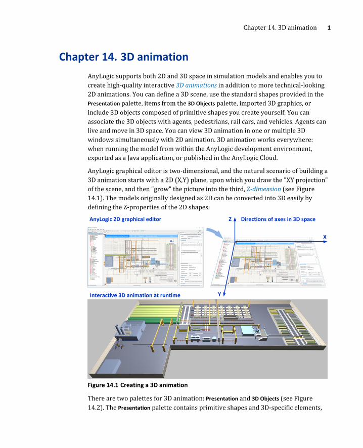
AnyLogic graphical editor is two-dimensional, and the natural scenario of building a 3D animation starts with a 2D (X,Y) plane, upon which you draw the "XY projection" of the scene, and then "grow" the picture into the third, Z-dimension (see Figure 14.1). The models originally designed as 2D can be converted into 3D easily by defining the Z-properties of the 2D shapes.
Figure 14.1 Creating a 3D animation
There are two palettes for 3D animation: Presentation and 3D Objects (see Figure 14.2). The Presentation palette contains primitive shapes and 3D-specific elements,
Y
Z AnyLogic 2D graphical editor Directions of axes in 3D space
Interactive 3D animation at runtime
X

2 The Big Book of Simulation Modeling · Multimethod Modeling with AnyLogic 8
such as 3D Window or Camera. The 3D Objects palette contains frequently used 3D graphics such as a person, a car, a forklift truck, a house, etc., that can be associated with static or dynamic objects in the model.
Figure 14.2 3D-related palettes
Example 14.1: A very simple model with 3D animation We will create a very simple model with 3D animation. In this model, sacks will be transported by conveyor through several manufacturing machines.
Follow these steps: 1. Create a new model.
Primitive shapes and 3D-specific elements
Frequently used 3D graphics
The highlighted elements can be
shown both in 2D and 3D

Chapter 14. 3D animation 3
2. Open the Presentation palette and use it to draw a background rectangle as shown in Figure 14.3.
3. Open the Material Handling Library palette and draw a Conveyor as shown in Figure 14.3. Set the conveyor properties, as shown.
4. Open the CNC section of the 3D Objects palette and drag the CNC Cutter 3 State 1 3D object on the background rectangle. In the same manner add the CNC Lathe Machine 4 State 1 3D object.
5. From the Manufacturing section drag the Inline Scanner 3D object. Arrange the objects over the conveyor as shown in Figure 14.3.
6. Open the Material Handling Library palette and put together a simple flowchart (Source -> Convey -> Sink).
7. Set the properties of the source block as shown. To adjust the New agent value, click the create a custom type label below. In the wizard opened, set the agent type name to Sack and select the Sack shape as the agent 3D animation.
8. Drag the 3D Window from the 3D section of the Presentation palette and place it next to the drawing. Set the Background color to antiqueWhite.
9. Run the model.
Figure 14.1 The "source code" of a simple model with 3D animation
conveyor Z: 10 Belt
rectangle Line color: no line Fill color: concrete texture Z: -1 Z-Height: 1
Source conveyor: conveyor Target conveyor: conveyor
Interarrival rate: 5 seconds New agent: Sack
3D Window
CNC Lathe Machine 4 State 1
Inline Scanner
CNC Cutter 3 State 1 Z: 5

4 The Big Book of Simulation Modeling · Multimethod Modeling with AnyLogic 8
At runtime, you can view 2D and 3D animations simultaneously. In the 3D window you can drag the scene, use the mouse wheel to zoom, or use Alt+drag to rotate the view.
Figure 14.2 "A very simple 3D model" at runtime
14.1. Primitive 3D shapes The presentation shapes appear in the 3D scene if their advanced Show in property is set to In 3D only or In 2D and 3D. By default, this setting is set to In 2D and 3D for all the shapes that may appear in 3D animation: line, polyline, rectangle, oval, arc, text, image.
In 3D, the rectangle shape will become a parallelepiped (a solid whose faces are all parallelograms) and the oval will become a cylinder (see Figure 14.3). The Z-coordinate of their bottoms, along with their Z-heights, are defined in the Position and size properties section. Do not confuse the Height of the rectangle and its Z-Height: the former becomes the parallelepiped’s length on Y-axis ("Y-Height") in 3D.
2D Animation
3D Animation

Chapter 14. 3D animation 5
Figure 14.3 3D Rectangle and 3D Oval. Z and Z-Height properties
The Z-coordinate of a shape is relative to the Z-coordinate of the level, where this shape lives.
Lines, polylines, and arcs have additional 3D properties. Lines and arcs have dZ – the difference in the Z coordinate of their start and end points. For a polyline, you can specify the Z-coordinate of each point in the Points section of properties. The 3D versions of these shapes are shown in Figure 14.4.
X
Z = 40
Y
Z
Z-Height = 30 Z: 0 Z-Height: 70
2D Editor 3D Scene
Y
X
Height

6 The Big Book of Simulation Modeling · Multimethod Modeling with AnyLogic 8
Figure 14.4 3D Line, 3D Polyline, and 3D Arc. dZ and Point Z properties
If Line color is set for a 3D shape, it becomes the color of its "walls,” both outside and inside. Fill color becomes the color of its "bodies" (see Figure 14.5).
Please note that if any two points of a polyline or start and end point of an arc have different Z coordinates, these shapes cannot be filled in 3D. They can only be filled if they have "flat surface.”
X
dZ = 30
Y
Z
Z-Height = 20
Z: 0 Z-Height: 20 dZ: 0
3D Line
0
Z: 0 Z-Height: 20
dZ: 30
Z[2] = 50
1
2
3
4
5
Z-Height = 40
Z[5] = -40
3D Polyline
Fill color: No fill Z: 0
Z-Height: 40 Points Z: 0, 0, 50, 0, 0, -40
3D Arc
dZ = 30
Z-Height = 5
Fill color: No fill Z: 0 Z-Height: 5 dZ: 30

Chapter 14. 3D animation 7
Figure 14.5 Line and fill colors of 3D shapes
Images and text can also appear in a 3D scene. Both have no Z-height (they are infinitely thin) and can be viewed both from the top and from underneath.
If two or more shape surfaces happen to be in the same plane and they intersect, the 3D renderer will not know how to display them. Undesired visual effects may then occur. To avoid this, you should slightly shift one of the surfaces by making the corresponding coordinates a bit different.
Consider Figure 14.6. To make the text appear nicely on top of the map, its Z coordinate was set to 1. Sometimes, one unit of difference is too much; in that case, you can set it to a fraction, say, 0.2 (this can be done in the properties of the shape).
Figure 14.6 Image and text in 3D scene. Undesirable rendering effects
Z: 0
Z: 1
If Zs were equal, you would see h
Line color: Wood texture Fill color: gray
Line color: gray Fill color: No fill
Line color: steelBlue Fill color: semi-transparent mediumTurquoise
Line color: No line Fill color: mediumPurple

8 The Big Book of Simulation Modeling · Multimethod Modeling with AnyLogic 8
The 2D order of shapes (the order that is controlled by the Send to Back/Bring to Front commands) does not affect the 3D scene at all. The shape that appears underneath another shape in 2D can be above it in 3D!
The 3D-related properties of shapes can be dynamic (see Section 12.3) and can be linked to model variables and expressions, just like any other properties. The Rotation of a shape is called Rotation Z, ° if the shape is marked as 3D. This is because the 2D rotation is the rotation in the (X,Y) plane around the Z axis.
You will find no fields for rotation in the (Y,Z) plane ("Rotation X") and rotation in the (X,Z) plane ("Rotation Y"). These cannot be controlled for individual shapes but can be controlled at the group level.
14.2. 3D groups and rotation 3D shapes can be grouped in the normal way. The group's Show in property "owns" the same property of all the group members. If a shape being grouped cannot be shown in 3D, e.g. a curve or a rounded rectangle, it will be invisible in the 3D scene.
When a shape becomes a part of a group, its Z-coordinate will become relative to the Z-coordinate of this group.
3D groups have dynamic Rotation X, rad and Rotation Y, rad properties, which allow you to rotate 3D shapes in the (Y,Z) and (X,Z) planes – this is the only place where you can do it.
Example 14.2: Rotation in 3D – a sign on two posts We will draw a sign with two posts. At design time, the sign will lie on the ground, i.e. in the (X,Y) plane. However, at runtime, it will be raised vertically by using the 3D group rotation properties.
Follow these steps: 1. Create a new model. 2. Draw the picture (as shown in Figure 14.7) using the text, rectangle, and
line elements from the Presentation palette. Set the Z-properties of the shapes as shown.
3. Select all shapes and group them. A new group is created, with the center approximately at the center of the picture.
4. Click the group and choose Select Group Contents from the context menu. 5. Move the group members up so that the group center is at the bottom of
the posts (see Figure 14.7 on the right).

Chapter 14. 3D animation 9
6. Select the group and open its Position and size properties section. Set Rotation X, rad to -PI/2.
Figure 14.7 A 3D group rotated in the (Y,Z) plane
7. Drag a 3D Window anywhere in the graphical editor. In its Scene properties section, set Grid color to white.
8. Run the model. The sign is displayed as being raised up, but the text appears distorted because its surface intersects with the surface of the sign (text's Z = 2 and it has no Z-height, and the sign's Z + Z-Height = 2 as well).
9. To fix this, open the Position and size section of the text properties and set Z to 2.1. This will position the text slightly above the sign surface.
10. Run the model again.
14.3. Standard and imported 3D graphics Primitive 3D shapes are primarily used to create simple 3D objects, or objects that dynamically change color, size, or have moving parts. To create more realistic (and attractive) 3D animations, you can use sophisticated 3D graphics (also called 3D models), both the standard, included in AnyLogic, and your own.
Using standard 3D graphics A collection of pre-drawn 3D graphics is available for your use in the 3D Objects palette (see Figure 14.2).
To use a standard 3D graphics: 1. Drag the 3D object from the 3D Objects palette in the graphical editor.
Z: 0 Z-Height: 2
Z: 2
Line width: 2 Z: 0 Z-Height: 2
The group center

10 The Big Book of Simulation Modeling · Multimethod Modeling with AnyLogic 8
2. AnyLogic will prompt you to resize the object automatically to make its size correspond to the current agent scale. We recommend confirming this action.
3. If required, set the additional scale and change orientation for the 3D object.
By default, the objects in the palette are put on the (XY) ground plane and are therefore seen in the graphical editor from the top. However, you can change this (see Figure 14.8). The default scale of objects is chosen to match the default library settings. For example: people, cars and trucks, trolleys, and security control devices are all in the same scale, which is consistent with the default scale of the Pedestrian Library. The scale of the rail cars and the containers matches the default scale of the Rail Library (see Chapter 9).
Figure 14.8 Orientation of 3D objects
The appearance of the 3D object is defined by its materials. You can customize the color of any material in a 3D object in the Colors section of the object’s properties.
The default orientation
Y
X
You may need to adjust the scale

Chapter 14. 3D animation 11
Figure 14.9 Color customization of 3D objects
To change the material’s color dynamically, use the setColor(String materialName, Color color) function of the 3D object. The materialName argument is the name of the material and the color argument is the color you want to assign to this material. For example, the expression truck.setColor(“Material_2_Surf”, white) will change the color of the truck’s cabin to white. If you provide null as the color argument, the specified material’s color will be reset to its default value.
All these dynamic changes will be visible in 3D scene only: in the graphical editor, the object will remain unchanged.
Using external 3D graphics AnyLogic uses Collada file format for 3D objects. A good collection of 3D models in public access can be found at 3D Warehouse (Trimble Inc., 2019).
To import 3D Warehouse graphics into AnyLogic: 1. Go to 3D Warehouse and choose a 3D model to download. The model
should be downloadable in Collada File (.DAE) format. 2. Save the 3D model. If it is in Collada format, it is usually a ZIP archive,
which you will then need to unzip. 3. In AnyLogic, open the 3D section of the Presentation palette and drag the 3D
Object in the graphical editor. 4. In the 3D object properties, choose the .dae file. Choose the appropriate
scale and orientation.
14.4. Hierarchical 3D animations. Embedded 3D presentation Just like with 2D animation, 3D animation in AnyLogic is hierarchical. The 3D presentation of an embedded agent can appear in the 3D scene of its container agent. The embedded agent presentation has the Show in option set to 2D and 3D and the Z property.

12 The Big Book of Simulation Modeling · Multimethod Modeling with AnyLogic 8
Figure 14.10 Embedded 3D presentation
The point of origin of the embedded airplane presentation is placed into its (X,Y,Z). Therefore, if you ask the airplane to move to (-100, 0, 100), it will arrive at (100, 100, 150) on Main.
The airplane agent has its own 3D scene (in our case, it only contains the airplane picture). This can be viewed by adding a 3D window in the Airplane editor and navigating to the airplane agent at runtime.
14.5. 3D Windows To view 3D animation in AnyLogic, you use 3D windows. The 3D Window element is located in the 3D section of the Presentation palette. In the Scene properties section of the 3D window, you can set up the background color and (optionally) the grid color. These properties are shared by all 3D windows in the agent type. The grid is drawn on the (X,Y) plane (see Figure 14.11) and has a step of 100 pixels.
Airplane has a 3D object in its presentation
The embedded presentation of airplane Show in: 2D and 3D X: 200 Y: 100 Z : 50
Airplane is embedded into Main
Main has its own 3D objects
Icon of the embedded Airplane agent
3D animation of Main
Z: 50
(200,100)

Chapter 14. 3D animation 13
Figure 14.11 3D window
Navigation in the 3D scene at runtime If you do not associate the 3D window with a camera (see Section 14.6). in the beginning it will take the default view on the 3D scene, trying to display the entire scene from some perspective. You can change the viewpoint by using the mouse and the Alt key (see Figure 14.12).
Design time Runtime
Objects in the distance are not displayed by the 3D engine
100 pixels

14 The Big Book of Simulation Modeling · Multimethod Modeling with AnyLogic 8
Figure 14.12 Navigation in the 3D scene
Sometimes you may wish to limit navigation. For example, you may not want the user to zoom in and out or to look below the ground level. You can limit navigation by choosing the appropriate Navigation type in the properties of the 3D window.
3D animation scene is rendered with a certain visibility depth, which is regulated by its far clipping distance, i.e. the distance in pixels from the camera at which the scene can be seen. The part of the 3D scene that is located beyond the far clipping distance will not be visible.
Greater far clipping distance can make your 3D animation more attractive by displaying more distant objects. At the same time, rendering a large number of objects consumes CPU time and may be inefficient. If the simulation performance becomes an issue, you may consider adjusting the far clipping distance for your 3D scene.
To adjust far clipping distance 1. In the Advanced section of the 3D window properties set the required value of
the Far clipping distance parameter.
Hold the left button and drag the mouse
Hold Alt key and drag the mouse
Rotate the mouse wheel
Full and Limited to Z above 0 are only available if the window is not following the camera
Chapter 14. 3D animation 15
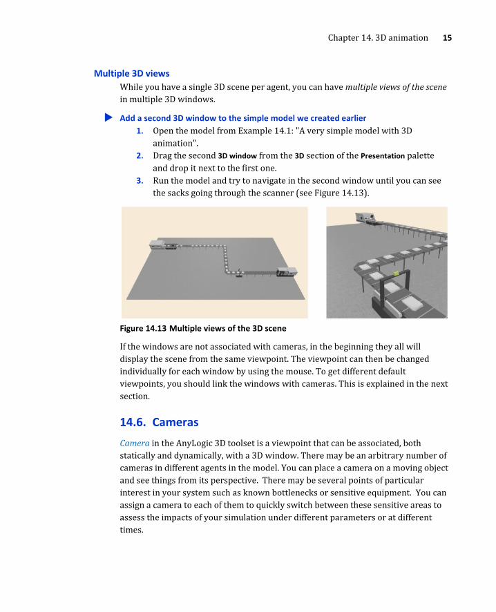
Multiple 3D views While you have a single 3D scene per agent, you can have multiple views of the scene in multiple 3D windows.
Add a second 3D window to the simple model we created earlier 1. Open the model from Example 14.1: "A very simple model with 3D
animation". 2. Drag the second 3D window from the 3D section of the Presentation palette
and drop it next to the first one. 3. Run the model and try to navigate in the second window until you can see
the sacks going through the scanner (see Figure 14.13).
Figure 14.13 Multiple views of the 3D scene
If the windows are not associated with cameras, in the beginning they all will display the scene from the same viewpoint. The viewpoint can then be changed individually for each window by using the mouse. To get different default viewpoints, you should link the windows with cameras. This is explained in the next section.
14.6. Cameras Camera in the AnyLogic 3D toolset is a viewpoint that can be associated, both statically and dynamically, with a 3D window. There may be an arbitrary number of cameras in different agents in the model. You can place a camera on a moving object and see things from its perspective. There may be several points of particular interest in your system such as known bottlenecks or sensitive equipment. You can assign a camera to each of them to quickly switch between these sensitive areas to assess the impacts of your simulation under different parameters or at different times.

16 The Big Book of Simulation Modeling · Multimethod Modeling with AnyLogic 8
Example 14.3: A very simple model with multiple 3D windows and cameras We will use the first model we created in this chapter and add the second 3D window and two cameras. The first one will be used as a default view for the first window, and the second one as the fixed unchangeable view for the second window.
The easiest way to tune the camera position is run the model, navigate a 3D window to the viewpoint you neeed, copy the viewpoint settings, and paste them into the camera properties in the editor.
Follow these steps: 1. Open the model from Example 14.1: "A very simple model with 3D
animation" 2. Drag the second 3D Window from the Presentation palette and place it to the
right of the first window. 3. Drag a Camera element from the Presentation palette to anywhere in the
graphical editor. 4. Run the model. 5. Adjust the view in the first 3D window so you can see the full scene from a
nice angle. 6. Right-click the 3D window and choose Copy camera location from the context
menu (see Figure 14.14). 7. Return to the graphical editor and select the camera. Click the Paste
coordinates from clipboard button in the camera properties (see Figure 14.14). The camera will jump to a new location and its rotation angles will change.
Figure 14.14 Tuning the camera position
1. Having adjusted the view in the 3D window, copy the viewpoint settings
2. Paste the settings in the camera properties
Runtime
Design tme

Chapter 14. 3D animation 17
8. Select the first 3D window. In its properties, set the Camera to the camera you have created. Do not select the Follow camera checkbox. Set Navigation type to Rotation only.
9. Run the model. The window now shows the scene from a different viewpoint. You can adjust it slightly, but you cannot zoom in or out.
10. Add another camera and use the same procedure (steps 5-9) to set the view in the second 3D window to the view at the start of the conveyor, focusing on the sacks leaving the CNC cutting machine.
11. In the properties of the second 3D window, select Follow camera and set Navigation type to None.
12. Run the model. Test navigation in both windows.
Example 14.4: Camera on a moving agent There are two ways you can move a camera. First, you can define dynamically changing coordinates and rotation in the camera properties. Secondly, you can put the camera on a moving agent. In this example, we will have an airplane with a camera that will fly over the US territory. We will use the function setCamera() of the 3D window to switch between the static and moving cameras.
First, create a 2D model: 1. Drag the Agent element from the Agent palette to the graphical editor. 2. On the first page of the New agent wizard, click the option A single agent
option. 3. On the next page of the wizard set the Agent type name to Airplane. The Agent
name will automatically change to airplane. Click Next. 4. On the next page of the wizard choose the 3D animation for the agent.
Select Airliner in the Airport section of the list and click Finish. 5. The airplane agent is created in Main. Go to the Airplane graphical editor and
set the additional scale of the Airliner 3D object to 10%. 6. In the Main graphical editor move the airplane animation to (0,0). 7. Open the Pictures palette and drag the USA Map element to Main. Place the
map in the upper right corner of the model’s frame and send it to the back. 8. Open the editor of the Airplane agent type again and go to the Agent actions
section of its properties. Type the following code in the On startup field: moveTo( uniform( 450 ), uniform( 300 ) ); This way, the airplane will make a move to a random location within the US map on the model startup.
9. Copy the piece of code in the On startup field and paste it in the On arrival to target location field. This code sends the airplane to a new random location once it has arrived at the previous one.
10. Run the model and watch the airplane fly in 2D.

18 The Big Book of Simulation Modeling · Multimethod Modeling with AnyLogic 8
Figure 14.15 Map of the USA and the airplane agent embedded in Main
Now, add the 3rd dimension to the model: 11. Open the editor of Main, select the USA map and set Show in to 2D and 3D in
its Advanced properties. 12. Select the animation of the embedded airplane and set its Z to 30 in the
Position and size properties section. The airplane will fly at this altitude. 13. Drag the 3D Window from the 3D section of the Presentation palette and drop
it below the map. 14. Run the model and see the airplane flying in 3D.
Figure 14.16 Camera on the airplane
Put a camera on the airplane: 15. Open the editor of Airplane and drag the Camera element from the 3D section
of the Presentation palette. Place the camera behind the tail of the aircraft and rotate it so that it looks toward the nose (see Figure 14.16).
The camera looks down
Animation of the embedded airplane agent at (0,0)

Chapter 14. 3D animation 19
16. In the Position section of the camera properties, set Z to 20. Combined with the camera’s default Rotation, X of 20 degrees, this raises the camera above the airplane and bends it a bit down so that we can see the airplane itself.
17. Open the editor of Main and add a Button from the Controls palette. Label the button "Airplane camera”. Type the following code in the button’s Action field: window3d.setCamera( airplane.camera, true ); This code switches the 3D window to the airplane camera. The boolean argument true tells the window to follow the camera.
18. Run the model, watch the 3D animation, and then click the button. The 3D window now shows the view from the (virtual) point behind and above the moving airplane (see Figure 14.17).
Figure 14.17 View from the airplane camera
We will now add a static camera and provide the ability to switch between the airplane camera and the static camera.
Add a static camera: 19. Open the graphical editor of Main and drag the Camera element from the 3D
section of the Presentation palette to the bottom left corner of the map. 20. Add a second Button from the Controls palette and label it "Static camera”.
Type the following code in the button Action field: window3d.setCamera( camera, false, 500 ); window3d.setNavigationMode( WINDOW_3D_NAVIGATION_FULL );
21. Run the model and switch between the static and moving cameras.
The first line of code in the button action switches the 3D window to the static camera. The middle argument false tells the window not to follow the camera, and the last optional argument defines a smooth 500 millisecond transition between the views (you may add the same smooth transition to the code of the first button). The second line of code restores the ability to fully navigate within the 3D space.

20 The Big Book of Simulation Modeling · Multimethod Modeling with AnyLogic 8
14.7. Lights To render the 3D scene, the 3D engine must know the sources and types of light. By default, the AnyLogic 3D engine assumes the presence of ambient light – the light that is everywhere (has no particular source), has no color, no direction and does not fade over distance as well as directional light – the light source located at some infinitely distant point, which produces an effect similar to sunlight. You can define your own lights in the 3D scene that will replace the default light. The lights can be of different types and can have customized color and attenuation. They can also be static as well as moving.
In total, there can be up to 6 lights per 3D scene, including the lights that come with the embedded agents.
The Light element belongs to the 3D section of the Presentation palette. In the properties, you can either choose one of the widely used predefined types of light or customize your own light source. Among the predefined types are daylight, moonlight, a street light, and a car headlight.
The available custom types are:
• Ambient – ubiquitous light that has no particular source and no direction, like the light on a cloudy day. The default light that is assumed in the scene without any light objects is ambient gray.
• Directional – light from a source that is so far away that the rays are parallel, like sunlight.
• Point – light from a point source that shines evenly in all directions. • Spot – light from a point source that shines only within a cone of a given
angle.

Chapter 14. 3D animation 21
Figure 14.18 Custom light types and properties of a spot light
All light color components interact with the object colors. If a light component is white or gray (evenly includes the whole spectrum), the objects will show in their natural colors. If, for example, the light color is pure red and the object color is pure blue, the object will not be visible. The purple object in the red light will show dark red, because only the red component of its color will interact with the light.
Imported 3D objects may have their own internal light sources. To avoid excessive illumination of such objects, the default setting of the 3D objects is to have the internal light source disabled. Alternatively, the internal light source can either illuminate only the 3D figure or the whole 3D scene.
Spot
Point
Ambient
Directional

22 The Big Book of Simulation Modeling · Multimethod Modeling with AnyLogic 8
Figure 14.19 A car and a motorcycle in different lights
Point and spot lights have the Attenuation property. Attenuation is the effect of light diminishing over distance. Constant attenuation means the light intensity is totally
Streetlight
Car headlight
Daylight Moonlight
Moonlight + Custom point light with red color
Scene lights are ignored + 3D object's internal lights illuminate the object
Moonlight + 3D object's internal lights illuminate the object
Moonlight + 3D object's internal lights illuminate the scene

Chapter 14. 3D animation 23
unaffected by distance. The intensity of the light with linear attenuation is inversely proportional to the distance from the light source.
For the spot light, it is also possible to customize the angle of light dispersion and change how quickly the light will fade as it moves from the axis of the cone of light.
Example 14.5: Examples of Lights in 3D Scene We will create a simple 3D scene with a road and a building with an entrance. We will illuminate the road with a streetlight and put an indoor spotlight inside the building. We will also create a car with headlights on it, and let it drive along the road to the entrance of the building.
Create a static 3D scene 1. Create a new model. 2. Use the Presentation palette to draw the background scene, as shown in
Figure 14.20. 3. Use the Space Markup section of the Road Traffic Library palette to draw the
road and the stop line. Make sure to draw the road from right to left; this will be the direction of the forward lane where the car will appear.
4. AnyLogic will prompt you to change the scale of your model to the one most frequently used in the road traffic models; accept the proposal.
5. Add some men in black suits (office workers from the 3D Objects palette) at the entrance of the building.
6. Add a 3D window, set its Background color to black and run the model. Notice how the scene looks like in the default light.

24 The Big Book of Simulation Modeling · Multimethod Modeling with AnyLogic 8
Figure 14.20 The 3D scene and its 3D view in the default light
Add static lights 7. Add a Light element from the 3D section of the Presentation palette and place
it anywhere. Choose the Moonlight light type and set the Color to darkGray. 8. Run the model again. The scene is now much darker, as we have replaced
the default light with very dark ambient light. 9. Add another light of the Street light type and place it near the road (see
Figure 14.21). Set its Color to darkGoldenRod. In the Position properties section, set the light’s Z to 50.
10. Run the model and view the scene. You can see the road lit by the streetlight.
11. Add another light, this time a Custom light of the Spot type and place it in the upper left corner of the building. Set the Color to slateGray and the Cut off angle to 45 (this makes the light cone wider). Set the light’s Z to 50, and Angle X, ° to 55 (this rotates the light cone downward).
12. Run the model and see the cone of the spotlight inside the building.
road: Road Number of forward lanes: 1 Number of backward lanes: 1 Z: 1
ground: Rectangle Fill color: grass texture Z: -1 Z-Height: 1
A group of men in black suites
(50,50)
(950,250)
floor: Rectangle Fill color: concrete texture Z: 0 Z-Height: 1
walls: Polyline Width: 4 Line color: brick texture Z: 0 Z-Height: 100
destination: Stop Line Visible: no

Chapter 14. 3D animation 25
Figure 14.21 The 3D scene with the custom lighting
Add a car driving with headlights 13. Go to the Road Traffic Library palette and drag the Car type element to the Main
graphical editor. Follow the New agent wizard’s instructions to create a new car type named Car with the default animation.
14. Add a light of the Car headlight type to the Car graphical editor and place it at the car windshield (see Figure 14.22). Set the light’s Z to 10 and Angle X, ° to 5.
15. Create a simple flowchart composed of the CarSource and CarMoveTo blocks from the Road Traffic Library and Delay and Sink blocks from the Process Modeling Library (see Figure 14.22).
16. In the properties of the carSource block, select the Limited number of arrivals option and type 1 in the Maximum number of arrivals field to allow only one car in the model.
17. Run the model.
Street light Color: darkGoldenRod
Custom spot light Color: slateGray Cut-off angle: 45 Z: 50, Angle X, °: 55
Moonlight Color: darkGray

26 The Big Book of Simulation Modeling · Multimethod Modeling with AnyLogic 8
Figure 14.22 Car with a headlight driving in a 3D scene
Car headlight Z: 10 Angle X, °: 5
Limited number of arrivals: on Maximum number of arrivals: 1 Road: road New car: Car
Delay time: 1 hour
Moves to: stop line Stop line: destination Behavior at stop line: Stop before stop line