chapter 14 accelerated and innovative bridge … 14 accelerated and innovative bridge construction...
TRANSCRIPT

Chapter 14 Accelerated and Innovative Bridge Construction
WSDOT Bridge Design Manual M 23-50.14 Page 14 - 1 - November2015
Chapter 14 Accelerated and Innovative Bridge Construction
14.1 Introduction 14.1.1 General 14.1.2 ABC Methods
14.2 Application of ABC 14.2.1 Economics of ABC 14.2.2 Practical Applications 14.2.3 Prefabricated Bridge Elements and Systems 14.2.4 Prefabricated Systems 14.2.5 Contracting Methods 14.2.6 Decision-Making Tools
14.3 Structural Systems 14.3.1 Precast Bent System Design for High Seismic Regions
14.3.1.1 Description of System 14.3.1.2 Design Philosophy 14.3.1.3 Design Provisions 14.3.1.4 Geometry and General Requirements 14.3.1.5 Joint Design for SDC A
14.3.1.5.1 Joint Performance 14.3.1.5.2 Joint Proportioning
14.3.1.6 Joint Design for SDC B 14.3.1.6.1 Joint Performance 14.3.1.6.2 Precast Connections
14.3.1.7 Joint Design for SDCs C and D 14.3.1.7.1 Local Displacement Capacity for SDCs B and C 14.3.1.7.2 Analytical Plastic Hinge Length 14.3.1.7.3 Joint Performance 14.3.1.7.4 Joint Proportioning 14.3.1.7.5 Socket-Type Footing Connections 14.3.1.7.6 Precast Column 14.3.1.7.7 Drilled Shaft 14.3.1.7.8 Superstructure Capacity Design for Integral Crossbeams
for Longitudinal Direction for SDCs C and D 14.3.1.7.9 Integral Crossbeam
14.3.2 Geosynthetic Reinforced Soil 14.3.3 Precast Decks
14.4 Innovative Bridge Construction 14.4.1 Self-Centering Columns 14.4.2 Shape Memory Alloy
14.5 Shipping, Handling and Erection 14.5.1 Lifting Devices 14.5.2 Handling and Storage 14.5.3 Tolerances

Chapter 14 Accelerated and Innovative Bridge Construction
WSDOT Bridge Design Manual M 23-50.14 Page 14 - 2 - November2015
14.5.4 Assembly Plans 14.5.5 Element Sizes
14.6 Installation Method Options 14.6.1 Crane Sizing
14.6.2 Lateral Sliding 14.6.3 Self-Propelled Modular Transporter (SPMT)
14.7 Examples of Accelerated and Innovative Bridge Construction Methods 14.8 References
Chapter 14 Accelerated and Innovative Bridge Construction
WSDOT Bridge Design Manual M 23-50.14 Page 14 - 3 - November2015
14. Accelerated and Innovative Bridge Construction
14.1 Introduction
14.1.1 General
The purpose of this chapter is to provide guidance for the planning and implementation of projects that may benefit from the application of rapid bridge construction technologies and methods. This chapter was prepared to provide bridge engineers with a basic understanding of different Accelerated Bridge Construction (ABC) methods available, help guide project specific selection of ABC methods, and to encourage the use of the ABC methods described in this chapter, or other innovative approaches to rapid bridge construction. It was also prepared to provide guidance with the design and detailing of precast concrete superstructure and substructure elements for accelerated bridge construction. For the sake of this chapter, ABC and Innovative Bridge Construction are encompassed in the term “ABC.”
This chapter is written in accordance with the AASHTO Guide Specifications for LRFD Bridge Seismic Design, 2nd Edition. It is WSDOT’s application of the Federal Highway Administration’s Every Day Counts Initiative. It is intended to compliment the documents listed below:
Accelerated Bridge Construction Manual, Publication Number FHWA-HIF-12-013 Development of a Precast Bent Cap System for Seismic Regions, NCHRP Report 681 Connection Details for Prefabricated Bridge Elements and Systems, Publication Number
FHWA-IF-09-010, March 2009
Modern implementations of ABC have been demanded by tight traffic control requirements in urban areas. Bridges used to be constructed on new alignments, connecting communities together in modern ways for the first time where there was no traffic and lower demand to travel from one community to another. Prior to modern times, the advancements made during the Industrial Revolution advanced new materials and construction techniques sped up construction. We saw bridge construction transform from stone construction used in ancient times, to include steel, concrete, and members subject to much larger forces than in the past. It’s the expressed desire here to apply the benefits of new advancements in materials and construction techniques to a wider array of projects and make the position of minimal time on site the expectation of every project.
The goal of ABC is to deliver projects earlier to the traveling public, reducing the impacts of on-site construction to motorists, promoting traveler and worker safety, and reducing environmental impacts. ABC uses different methods of project delivery and construction to reduce the project schedule, on-site construction time, and public impact. With the ever increasing demand on transportation infrastructure, and the number of bridges that are approaching the end of their service lives, the need for ABC becomes more apparent. ABC should be viewed as a subset of a larger accelerated project delivery effort encompassing all aspects of project development including contract administration through construction contract acceptance.
ABC methods are generally safer than conventional construction methods because much of the construction can be done offsite, away from traffic. Quality can also be improved because the

Chapter 14 Accelerated and Innovative Bridge Construction
WSDOT Bridge Design Manual M 23-50.14 Page 14 - 4 - November2015
construction is often completed in a more controlled environment compared to on-site conditions. Ease of construction and design can be improved as standardized bridge pieces are developed. The use of ABC comes with challenges that need to be overcome on a project-specific basis, often accelerating the schedule increases the cost of the project. This increased project delivery cost can be offset by reductions in road user costs and economic loss to the affected communities. 14.1.2 ABC Methods
Many different methods to facilitate ABC are available. Some of those methods are discussed in greater detail later in this Chapter. They include precast bridge piers, geosynthetic reinforced abutments with precast slab or deck girder superstructures, precast decks, precast footings or entire abutments, or any combination thereof. Installation of these bridge elements can be aided with use of lateral sliding of large bridge members or self-propelled modular transporters, or heavy cranes. Contractually, ABC can be aided with the use of alternate contracting methods such as those described below. 14.2 Application of ABC 14.2.1 Economics of ABC
Long construction time allotments may provide for a cheaper bottom line on a project. But they introduce a number of unassigned risks that provide an intangible cost to the contractor, and ultimately to the state.
Construction times have significant economic cost to the state through traffic delays and interruption to commerce. It may come as longer traffic jams in already busy urban areas, or as crowded interstates between urban centers, especially on holiday weekends, and subsequent traffic jams on local roads adjacent to the highway. It’s impossible to know how many businesses are affected when a highway is jammed for many years while it is widened. Considerations related to lane rental rates should be considered as part of this to address funding issues.
The risk of injury to the traveling public also affects the cost to a project. The loss of one life of someone traveling through a construction zone not only devastates the lives of those affected, but it can cost the state a lot of money in compensation for the families of those individuals. And while we expect the public to travel safely through our work zones, the reality is they often do not. Shorter construction times saves lives, and it saves money.
Predicting a reliable cost associated with these risks is impossible. The best method to minimize costs associated with either of these risks is to minimize the exposure time to these risks. With the estimating tools available, estimates of these costs demonstrate an overall project savings to the end users when projects are constructed with rapid construction methods.
Another cost to consider is estimating the cost of unfamiliar technologies. Until ABC methods are more fully understood by contractors, the estimated costs of the tangible and familiar things

Chapter 14 Accelerated and Innovative Bridge Construction
WSDOT Bridge Design Manual M 23-50.14 Page 14 - 5 - November2015
will likely be higher than methods common today. This is due to the added risk associated with those unfamiliar construction techniques. With more exposure and familiarity come lower costs as a contractor develops their means and methods. With the risks mentioned above, in some states, it has been shown that a high percentage of the public approves the use of ABC, knowing that the immediate project cost can be significantly higher. 14.2.2 Practical Applications
Locations where time is critical, or access is difficult are where ABC Construction methods would be most fully utilized. Building piers in busy highway medians, installing columns in waters with narrow fish window times, or building bridges on mountain roads far from concrete production facilities are excellent places to consider ABC. ABC Methods may also be fitting for construction over a large body of water, where access is difficult and heavy moving equipment, perhaps on a barge, is easy to bring to the site. Pouring concrete underwater can be difficult, and perhaps installing a precast element in the water may be easier than constructing a coffer dam.
Other locations to consider are where the overall footprint of a job site may be a concern. Realize that accessing the connections of precast members can take up a lot of space and may not be necessary. Rebar would come with the precast member instead of being placed before the concrete, eliminating the need for access for workers and equipment near to the ends of the precast member. By moving more duties off site, less space is need on site, and the offsite location could be at a less sensitive location. If there were concerns with disturbing the adjacent ground, smaller construction sites near a bridge could be beneficial.
Bridge designs with many similar pieces, such as long retaining walls, bridge decks, or bridges with many piers are also good candidates for ABC. The smaller pieces can be shipped in on semi-trucks and placed immediately. The repetition would bring more economic value to the ABC component of the project and bring the cost of the precast piece down.
Often precast pieces can be used to provide a structural shell that will serve multiple purposes. Precast pieces can be used to form a caisson or a coffer dam that will define a dry work zone which be filled in with concrete later. The shell could simply provide a void that makes shipping a piece easier, which will get filled with concrete when another bridge portion is poured.
Construction schedules can make ABC worth considering. Lateral sliding of bridge superstructures have been used such that an existing bridge can be used until the critical moment where one bridge is rolled out, and a new one rolled in. Months of construction can take place next to the location the bridge would be used, and in a matter of hours the new structure could be slid into place.
In general, where time on a job site ought to be minimized, ABC would make a good choice to consider. 14.2.3 Prefabricated Bridge Elements and Systems

Chapter 14 Accelerated and Innovative Bridge Construction
WSDOT Bridge Design Manual M 23-50.14 Page 14 - 6 - November2015
For the sake of bridge design, use of Prefabricated Bridge Elements and Systems (PBES) is one strategy that can meet the objectives of accelerated bridge construction. PBES are structural components of a bridge that are built offsite, or near-site of a bridge, and include features that reduce the onsite construction time and mobility impact time that occur from conventional construction methods. PBES includes innovations in design and high-performance materials and can be combined with the use of "Fast Track Contracting" methods. Because PBES are built off the critical path and under controlled environmental conditions, improvements in safety, quality, and long-term durability can be better achieved.
Prefabricated bridge elements can also be used in combination with other accelerated bridge construction methods. Commonly used prefabricated bridge elements are pre-stressed concrete girders, including I-girders, adjacent inverted T-beams and boxes, full depth and partial depth deck panels, abutments, pier crossbeams, pier columns, and footings, as well as precast three-sided and four-sided box culverts.
Prefabricated bridge elements are used to mitigate the on-site time required for concrete forming, rebar tying and concrete curing, saving weeks to months of construction time. Deck beam elements eliminate conventional onsite deck forming activities. To reduce onsite deck forming operations, deck beam elements are typically placed in an abutting manner.
Prefabricated elements are often of higher quality than conventional field-constructed elements, because the concrete is cast and cured in a controlled environment. The elements are often connected using high strength grout, and post-tensioning or pre-tensioning. Close attention should be given to these connections.
Connection strength is often a concern when with PBESs. There are many tools available to provide durable, high strength connections. The grouted duct technology discussed in detail later in this chapter is one method. Other methods are grouted duct couplers, key and socket connections, and cast-in-place joints encompassing precast members with high strength concrete.
A. Prefabricated Elements
Prefabricated Elements are a category of PBES which comprise a single structural component of a bridge. Under the context of ABC, prefabricated elements reduce or eliminate the onsite construction time that is needed to build a similar structural component using conventional construction methods. An element is typically built in a prefabricated and repeatable manner to offset costs.
B. Bridge Deck Elements
Bridge deck elements eliminate activities that are associated with conventional bridge deck construction, which typically includes onsite installation of forms, overhang bracket and formwork installation, reinforcing steel placement, paving equipment set up, concrete placement, and concrete curing, all typically occurring in a sequential manner.
Examples of Bridge Deck Elements include:

Chapter 14 Accelerated and Innovative Bridge Construction
WSDOT Bridge Design Manual M 23-50.14 Page 14 - 7 - November2015
partial-depth precast bridge deck panels full-depth precast bridge deck panels with and without longitudinal post-tensioning lightweight precast bridge deck panels FRP bridge deck panels steel grid (open or filled with concrete) orthotropic bridge deck other prefabricated bridge deck panels made with different materials or processes
C. Beam Elements
Beam Elements are composed of two types: "deck beam” elements and "full-span" beam elements.
Deck Beam Elements eliminate conventional onsite deck forming activities as noted above. To reduce onsite deck forming operations, deck beam elements are typically placed in an abutting manner.
Examples of Deck Beam Elements include:
adjacent deck bulb tee beams adjacent double tee beams adjacent inverted tee beams adjacent box beams or voided slabs modular beams with decks post-tensioned concrete thru beams other prefabricated adjacent beam elements
Note: Although not preferred under the context of ABC, a separate construction phase, performed in an accelerated construction manner, may be required to finish the deck. A deck connection closure pour, overlay, or milling operation using innovative materials can be used to expedite the completion of the deck. In some situations, the placement of overlays can be accomplished during off-peak hours after the bridge is opened to traffic.
Full-span beam elements eliminate conventional onsite beam placement activities. They are typically rolled, slid, or lifted into place to allow deck placement operations to begin immediately after placement. Given their size and weight, the entire deck is not included.
Examples of Full-Width Beam Elements include:
truss span without deck arch span without deck other prefabricated full-width beam element without deck
D. Pier Elements
Pier elements eliminate activities that are associated with conventional pier construction, which typically includes onsite form installation, reinforcing steel placement, concrete placement, and concrete curing, all typically occurring in a sequential manner.
Examples of Pier Elements include:

Chapter 14 Accelerated and Innovative Bridge Construction
WSDOT Bridge Design Manual M 23-50.14 Page 14 - 8 - November2015
prefabricated caps for caisson or pile foundations precast spread footings prefabricated columns prefabricated column crossbeams prefabricated combined crossbeams and columns other prefabricated pier elements
E. Abutment and Wall Elements
Abutment and wall elements eliminate activities that are associated with conventional abutment and wall construction, which typically includes form installation, reinforcing steel placement, concrete placement, and concrete curing, all occurring in a sequential manner.
Abutment and wall elements may be built in a phased manner using conventional construction methods, but under or near an existing bridge without disrupting traffic.
Examples of Abutment and Wall Elements include: prefabricated caps for caisson or pile foundations precast footings, wingwalls, or back walls sheet piling, steel or precast concrete prefabricated full height wall panels used in front, behind, or around foundation
elements cast-in-place concrete abutments and walls used with or without precast elements if
built in a manner that is accelerated, or has no impact to mobility Mechanically Stabilized Earth (MSE), modular block, or proprietary walls,
Geosynthetic Reinforced Soil (GRS) abutment other prefabricated abutment or wall elements
F. Miscellaneous Elements
Miscellaneous elements either eliminate various activities that are associated with conventional bridge construction or compliment the use of PBES.
Examples of Miscellaneous Elements include: precast approach slabs prefabricated parapets deck closure joints overlays that can be placed in an accelerated construction manner that
complements or enhances the durability and rideability of the prefabricated element other prefabricated miscellaneous elements
Note: Any cast-in-place concrete or overlay placement operation should be performed in a manner that reduces the impacts to mobility. This may require work that is performed under "Fast Track Contracting" methods with incentive/disincentive clauses, nighttime or off-peak hour time frames, or work done entirely off line. Innovative materials may be needed to expedite placement times such as the use of rapid-set/early-strength-gain materials or Ultra High Performance Concrete (UHPC) in closure pours.

Chapter 14 Accelerated and Innovative Bridge Construction
WSDOT Bridge Design Manual M 23-50.14 Page 14 - 9 - November2015
14.2.4 Prefabricated Systems
Prefabricated Systems are a category of PBES that consists of an entire superstructure, an entire substructure, or a total bridge that is procured in a modular manner such that traffic operations can be allowed to resume after placement. Prefabricated systems are rolled, launched, slid, lifted, or otherwise transported into place, having the deck and preferably the barriers in place such that no separate construction phase is required after placement. Due to the manner in which they are installed, prefabricated systems often require innovations in planning, engineering design, high-performance materials, and "Structural Placement Methods".
Benefits of using prefabricated systems include:
Minimal utility relocation and right-of-way take, if any at all No-to-minimal traffic detouring over an extended period of time Preservation of existing roadway alignment No use of temporary alignments No temporary bridge structures No-to-minimal traffic phasing or staging Superstructure Systems: Superstructure systems include both the deck and primary
supporting members integrated in a modular manner such that mobility disruptions occur only as a result of the system being placed. These systems can be rolled, launched, slid, lifted, or transported in place, onto existing or new substructures (abutments and/or piers) that have been built in a manner that does not impact mobility.
Examples of Superstructure Systems include:
full-width beam span with deck through-girder span with deck truss span with deck arch span with deck other prefabricated superstructure systems
Total Bridge Systems: Prefabricated superstructure/substructure systems include either the interior piers or abutments which are integrated in a modular manner with the superstructure as described above. Superstructure/substructure systems can be slid, lifted, or transported into place onto new or existing substructures that have been built in a manner that does not impact mobility.
Examples of Total Bridge Systems include:
rigid frames with decks and parapets other prefabricated superstructure/pier systems
14.2.5 Contracting Methods

Chapter 14 Accelerated and Innovative Bridge Construction
WSDOT Bridge Design Manual M 23-50.14 Page 14 - 10 - November2015
At WSDOT, region engineers determine which contracting method ought to be employed at about the time a project is scoped. WSDOT’s Design Manual ought to be considered by region engineers. Realize the bridge engineer may not be a part of that portion of the project’s development. Tools commonly considered by region engineers are various contracting methods, incentivizing techniques and ways to provide options in contracting to get the most value out of a project.
Funding may be available from FHWA for ABC type projects, or projects focused on achieving the goals of the Everyday Count Initiative. 14.2.6 Decision Making Tools
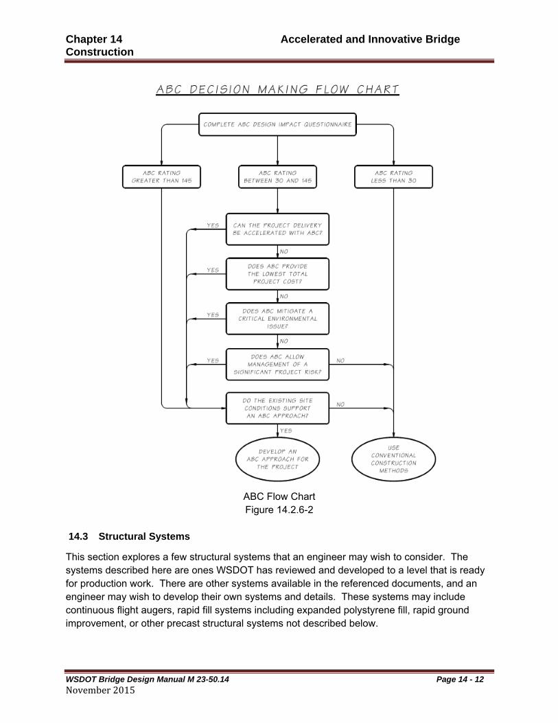
Figures 14.2.6-1 and 14.2.6-2 are tools that should be used for each bridge project, and considered at the Preliminary Plans stage of each project, or sooner. Both of these tools shall be used. It is expected each project will consider ABC to some degree. The questionnaire and flowchart provide some rational measure for how well suited a project may be for ABC.
The questionnaire is intended to review the entire project, including items beyond the immediate interests of the bridge, and assign a measure of relevance and priority to each item of concern. This assures that not only is a specific item being considered, but so is its significance to the project. The relevance value should be multiplied by the priority value for each question. The product of each of those numbers shall be added up at the bottom of the questionnaire, and that number will be the ABC Rating.
The flow chart is intended to be a situational evaluation regardless of magnitude or relevance of other items. To use the flowchart, the ABC Rating needs to be determined from the questionnaire, and the path one takes through the flowchart is based upon that rating. The expectation is that if ABC can be considered for a project with even a slight possibility for using ABC, it should be. At the end of the flowchart is the direction the designer ought to pursue. The designer will be instructed to either develop an ABC approach or consider conventional methods.

Chapter 14 Accelerated and Innovative Bridge Construction
WSDOT Bridge Design Manual M 23-50.14 Page 14 - 11 - November2015
ABC Questionnaire
Figure 14.2.6-1
Chapter 14 Accelerated and Innovative Bridge Construction
WSDOT Bridge Design Manual M 23-50.14 Page 14 - 12 - November2015
ABC Flow Chart Figure 14.2.6-2
14.3 Structural Systems
This section explores a few structural systems that an engineer may wish to consider. The systems described here are ones WSDOT has reviewed and developed to a level that is ready for production work. There are other systems available in the referenced documents, and an engineer may wish to develop their own systems and details. These systems may include continuous flight augers, rapid fill systems including expanded polystyrene fill, rapid ground improvement, or other precast structural systems not described below.
Chapter 14 Accelerated and Innovative Bridge Construction
WSDOT Bridge Design Manual M 23-50.14 Page 14 - 13 - November2015
This section discusses the precast bent system in great detail. WSDOT has worked closely with researchers and is a leader in pursuing its development and considers this chapter an excellent guide for its design. While there’s a lot of detail on the precast bent system discussed here, there are other resources available for the application of the other systems discussed. Those other resources ought to be reviewed when considering these systems.
14.3.1 Precast Bent System Design for High Seismic Regions
Increasingly, construction methods that speed up bridge construction are being utilized to minimize traffic disruption and improve safety of both construction workers and the traveling public. Often, prefabricated structural elements are used to speed up construction. Unfortunately, elements that speed up construction often are not appropriate when moderate to high seismic effects are expected. This article summarizes a precast bent system that has been developed to both speed up construction and perform well under seismic loading. The system is often referred to as the Highways for Life (HfL) system, Precast Pier System, or Precast Bent System. It’s configured to be used with precast girder superstructures that are supported on crossbeams that are constructed in two phases. The first or lower-stage crossbeam is constructed, the girders are then set on this beam, and finally the second or upper-stage crossbeam is constructed using cast-in-place concrete to integrate the superstructure and substructure. This precast bent system is an adaptation of a common type of reinforced concrete bent or pier construction used throughout the United States. It utilizes the grout duct technology developed through university research.
Unique features of the precast bent system are a socket connection at the column-to-foundation connection and a grouted-duct arrangement at the column-to-crossbeam connection. This system utilizes precast columns and precast lower-stage crossbeams. The system also can include splices in the column to facilitate weight control for the columns, whereby splitting the column into multiple segments. This can control the weight of precast elements that must be transported. Similarly the precast crossbeam can be split into segments for the same reason. Both of these splice connections are configured to be capacity protected for seismic forces. The lower column socket connection has also been configured to be used with spread footings, pile caps and drilled shafts.
Large-scale laboratory testing has been completed and is reported in companion reports specifically covering each connection type. Design provisions have been crafted for use by designers to supplement the AASHTO Guide Specifications for LRFD Seismic Bridge Design, 2nd Edition. Construction specifications are included in this chapter, as are design examples.
A demonstration project was constructed using this technology on a bridge in Washington State over Interstate 5, Bridge Number 12/118. The details of the design for this project are included in the paper “Accelerated Bridge Construction in Washington State: From Research to Practice” in the Fall 2012 PCI Journal, and so are construction photos and a lessons-learned section relating the construction contractor’s feedback following construction. The development and deployment of this technology has been a success, and the owner, the Washington State Department of Transportation, continues to look for opportunities to apply the technology, along

Chapter 14 Accelerated and Innovative Bridge Construction
WSDOT Bridge Design Manual M 23-50.14 Page 14 - 14 - November2015
with other methods, to accelerate bridge construction in the state. The demonstration bridge is currently in service and is performing well, but has not been tested by an actual earthquake.
Design examples for precast bents can be found in the following publications:
Precast Bent Systems for High Seismic Regions Appendix B, Publication Number FHWA-HIF-031-037-B.
Precast Bent Systems for High Seismic Regions Appendix C, Publication Number FHWA-HIF-031-037-C.
14.3.1.1 – Description of System
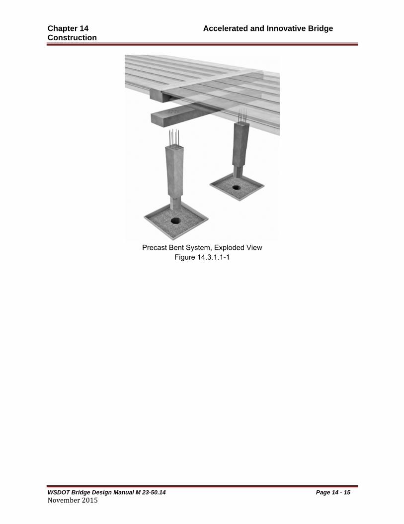
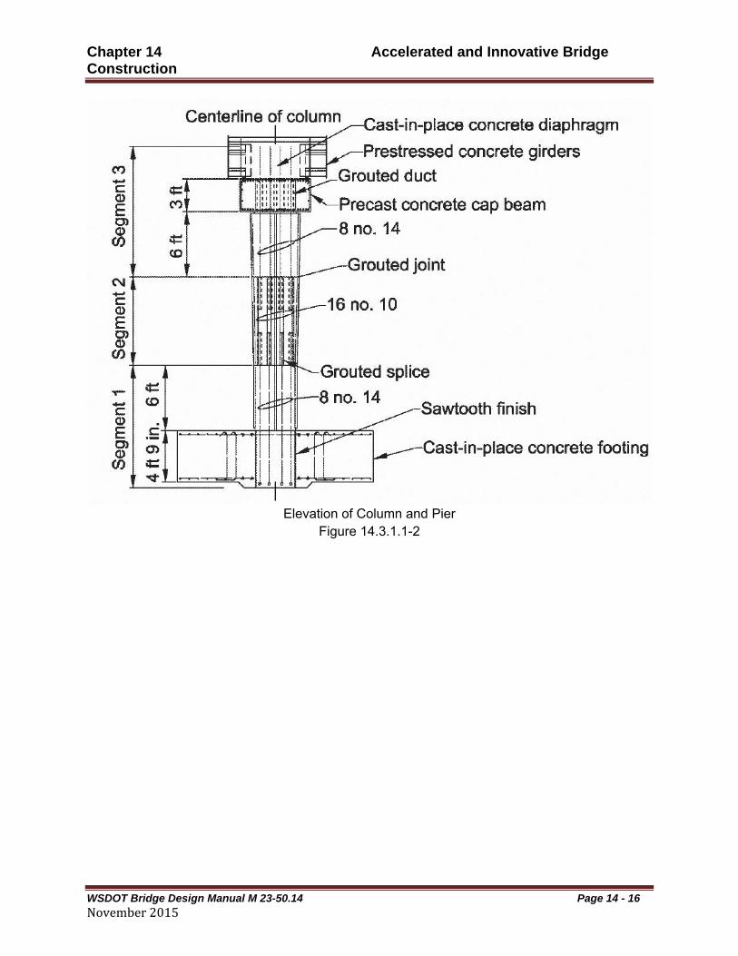
The bent system is comprised of precast columns supported by either spread footings or drilled shafts and a precast crossbeam that supports pre-stressed concrete girders. The bent is integrated with the superstructure using a cast-in-place full concrete diaphragm. The crossbeam thus created is a two-stage dropped crossbeam with the lower precast portion known as the first stage crossbeam and the upper diaphragm known as the second stage of the crossbeam. The bridge deck slab is cast on top of the girders and diaphragm. This concept is illustrated in Figures 14.3.1.1-1, 14.3.1.1-2 and 14.3.1.1-3.
The system consists of a socket connection at the foundation level and a grouted bar connection to the crossbeam. The foundation must be cast around the precast column to form the socket connection, and the interface between the column and foundation must be intentionally roughened to ensure vertical load carrying capacity. In the HfL Bent System, the connection to the crossbeam is intended to consist of large diameter bars such that fewer bars are required. These bars are grouted into steel ducts with generous diameters relative to the bars, 2 to 3 inches larger in diameter, to facilitate fit up as shown in Figure 14.3.1.1-1.
For many typical bridges a single precast column element is sufficient. However, the segmental column concept was included in the validation and HfL demonstration project.
Chapter 14 Accelerated and Innovative Bridge Construction
WSDOT Bridge Design Manual M 23-50.14 Page 14 - 15 - November2015
Precast Bent System, Exploded View
Figure 14.3.1.1-1
Chapter 14 Accelerated and Innovative Bridge Construction
WSDOT Bridge Design Manual M 23-50.14 Page 14 - 16 - November2015
Elevation of Column and Pier
Figure 14.3.1.1-2

Chapter 14 Accelerated and Innovative Bridge Construction
WSDOT Bridge Design Manual M 23-50.14 Page 14- 17 November2015
Elevation and Sections of Column and Pier Figure 14.3.1.1-3

Chapter 14 Accelerated and Innovative Bridge Construction
WSDOT Bridge Design Manual M 23-50.14 Page 14- 18 November2015
14.3.1.2 Design Philosophy
This process emulates cast-in-place connections with precast elements. CIP construction joints are typically detailed with dowels and lap splices. Emulation design replaces the traditional lap splice with a grouted duct sleeve. The design of column connections is especially difficult for high seismic zones. Confinement of column reinforcing is possible with precast concrete elements. The AASHTO design specifications do not mandate the confinement reinforcing bars be continuous from the column into the adjacent members footing or crossbeam. The confinement reinforcing can be terminated in the column and separate confinement reinforcement can be added to the adjacent element. 14.3.1.3 Design Provisions
The provisions specified in this Section 14.3, provide additional requirements to those in the main body of the AASHTO Guide Specifications for LRFD Seismic Bridge Design, 2nd Edition (AASHTO Seismic). Requirements below shall be followed when designing a precast bent system. Sections of AASHTO Seismic that are not changed herein still apply to the design of the bent system. 14.3.1.4 Geometry and General Requirements
Geometric requirements are driven by the research that supports the development of the precast bent system. The intent of this article is to describe the type of construction tested by universities to support the documents listed in Section 14.1.1. It is expected that any geometric configuration selected would have adequate university research behind it to support it. If university research has been performed defending new geometric conditions, they may be used if approved by the WSDOT Bridge Design Engineer.
The following geometry requirements shall apply to precast bent systems without approval of the WSDOT Bridge Design Engineer:
Columns shall be located under crossbeams. Grouted ducts shall have their centerlines oriented vertical. Footings abutting precast columns shall be poured around the end of the column. No grouted ducts allowed in footings. Precast columns shall not be connected to precast footings. Crossbeam splices shall be lapped rebars constructed within a cast-in-place closure
pour. Crossbeam splices shall be located at points of counter flexure of the crossbeam and
not within Beff of the column, as defined in Section 5.1.3.D.3. Column splices shall incorporate grouted ducts on at least one abutting end of a column
within a joint. Rebar that is expected to protrude into a duct shall be cast with the rest of the column segment.
Geometric requirements required in other bridge design requirements shall still be met.
Other requirements are listed below:

Chapter 14 Accelerated and Innovative Bridge Construction
WSDOT Bridge Design Manual M 23-50.14 Page 14- 19 November2015
WSDOT’s Standard Specifications shall be followed. Grouted ducts shall be a semi-rigid, galvanized, ferrous, corrugated metal duct. Concrete segments may be constructed on site or at a precast manufacturing facility.

Chapter 14 Accelerated and Innovative Bridge Construction
WSDOT Bridge Design Manual M 23-50.14 Page 14- 20 November2015
Embedment requirement for grouted duct splices, regardless of seismic design category, are shown in Table 14.3.1.4-1.
Bar Size
Nominal Duct Size (in.)
Embedment / Bar Diameter
Embedment Length, (in.)
#3 2 29 12
#4 2.5 27 15
#5 3 21 15
#6 3 18 15
#7 3 21 20
#8 3.5 18 20
#9 3.5 16 20
#10 3.5 18 25
#11 4 16 25
#14 4 16 30
#18 4.5 16 40
Embedment Requirement for Grouted Duct Splices Table 14.3.1.4-1
14.3.1.5 Joint Design for SDC A
Interior joints of multi-column bents shall be considered “T” joints for joint shear analysis. Exterior joints shall be considered knee joints and require special analysis and detailing that are not addressed herein, unless special analysis determines that “T” joint analysis is appropriate for an exterior joint based on the actual bent configuration. 14.3.1.5.1 Joint Performance
Moment-resisting connections shall be designed to transmit the unreduced elastic seismic forces in columns.
Bridges designed for SDC A are expected to be subjected to only minor seismic displacements and forces; therefore, a force-based approach is specified to determine unreduced elastic seismic forces, in lieu of a more rigorous displacement-based analysis. However, some SDC A bridges may be exposed to seismic forces that may induce limited inelasticity, particularly in the columns. For this reason, AASHTO Seismic 8.2 states that when SD1 is greater than or equal to

Chapter 14 Accelerated and Innovative Bridge Construction
WSDOT Bridge Design Manual M 23-50.14 Page 14- 21 November2015
0.10 but less than 0.14, minimum column shear reinforcement shall be provided according to the requirements of AASHTO Seismic 8.6.5 for SDC B subject to AASHTO Seismic 8.8.9 for the length over which this reinforcement is to extend.
Although AASHTO Seismic 8.8.9 does not specify placement of transverse column reinforcement into the joint, Sections 5.10.11.4.1e and 5.10.11.4.3 of the AASHTO LRFD Bridge Design Specifications referenced by the alternative provisions in AASHTO Seismic 8.2 and 8.8.9 specify placement of transverse reinforcement into the joint for a distance not less than one-half the maximum column dimension or 14.0 in. from the face of the column connection into the adjoining member. Therefore, according to these alternative provisions, when SD1 is greater than or equal to 0.10 but less than 0.14, minimum transverse reinforcement is required for cast-in-place joints. When SD1 is less than 0.10, transverse shear reinforcement is not required. For all values of SD1 in SDC A, the designer may choose to conservatively provide a “rational” design for joint reinforcement as specified in AASHTO Seismic 8.13 and C8.13.1.
Precast crossbeam connections for SDC B, C, and D are designed and detailed to provide a force transfer mechanism through the joint and crossbeam based on research. The precast crossbeam design provisions for SDC A are more than those for SDC B, but are deemed appropriate for all values of SD1 in SDC A. 14.3.1.5.2 Joint Proportioning
A. Precast Crossbeam Connections
The provisions of AASHTO Seismic 8.13.2 shall be used for joint proportioning, except that the nominal yield stress of the column longitudinal reinforcement may be used in lieu of the expected yield stress.
For SDC A, joint proportioning of crossbeams only requires the designer to provide sufficient length to anchor column longitudinal reinforcement in the joint. Minimum embedment length provisions in Table 14.3.1.4-1 for column longitudinal reinforcement anchored in precast crossbeam connections are appropriate.
B. Grouted Duct Connection
Transverse reinforcement in the form of tied column reinforcement, spirals, hoops, or intersecting spirals or hoops shall be provided. Minimum transverse reinforcement in the joint for grouted duct connections shall be based on AASHTO Seismic Equation 8.13.3-1 and 8.13.3-2. Spacing of transverse reinforcement shall not exceed 0.3DS or 12 in, where Ds is the depth of the superstructure.
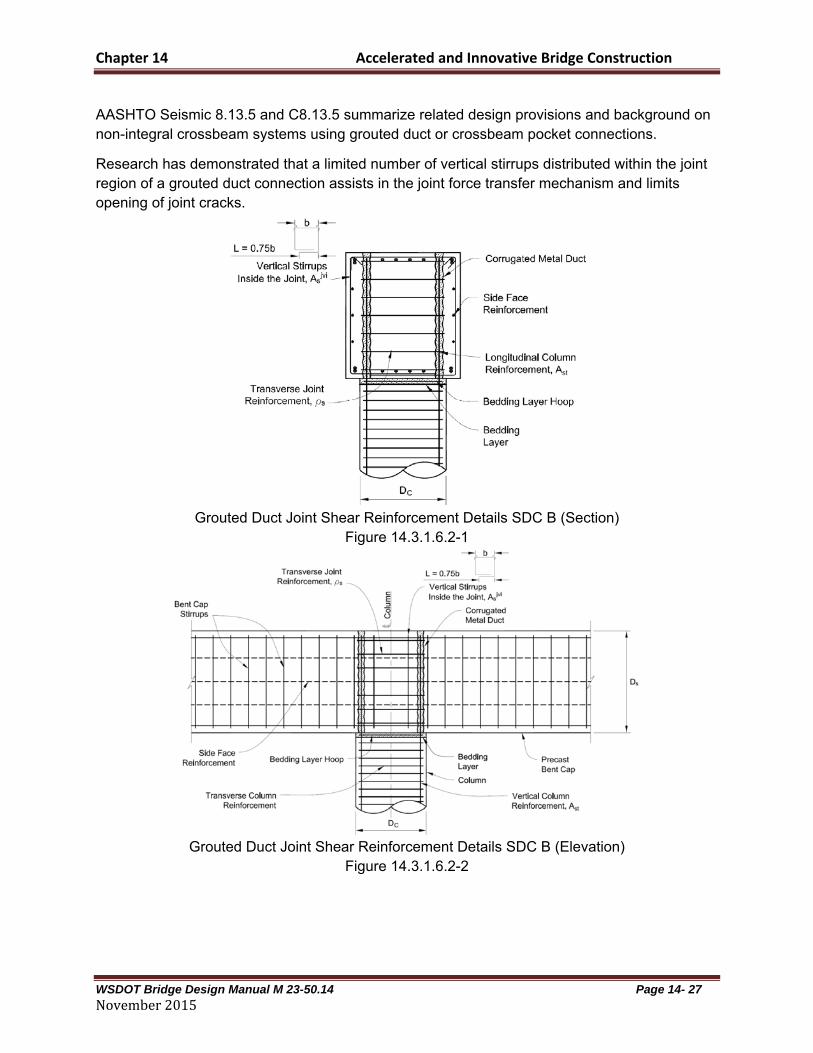
AASHTO Seismic 8.13.5 and C8.13.5 summarize related design provisions and background on non-integral crossbeam systems using grouted duct or crossbeam pocket connections.
Minimum transverse reinforcing in the joint is required to help ensure the connection does not become a weak link in a precast bent system. However, the additional joint shear reinforcement required for SDC B, C, and D is not required.

Chapter 14 Accelerated and Innovative Bridge Construction
WSDOT Bridge Design Manual M 23-50.14 Page 14- 22 November2015
Grouted duct connections shall be reinforced such that vertical stirrups with a total area, jvisA ,
spaced evenly over a length Dc through the joint shall satisfy:
stjvi
s AA 08.0 Equation 14.3.1.5.2-1
and shall be detailed as shown in Figure 14.3.1.5.2-1 through Figure 14.3.1.5.2-3. Details of the connection include ducts, vertical stirrups inside the joint, and bedding layer reinforcement are shown in Figure 14.3.1.5.2-1.
Grouted Duct Joint Shear Reinforcement Details SDC A (Section) Figure 14.3.1.5.2-1

Chapter 14 Accelerated and Innovative Bridge Construction
WSDOT Bridge Design Manual M 23-50.14 Page 14- 23 November2015
Grouted Duct Joint Shear Reinforcement Details SDC A (Elevation)
Figure 14.3.1.5.2-2
Grouted Duct Joint Shear Reinforcement Details SDC A (Plan)
Figure 14.3.1.5.2-3
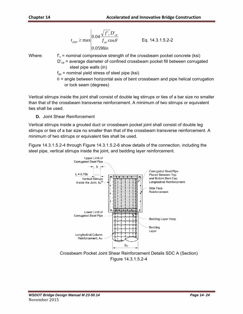
C. Crossbeam Pocket Connection
A minimum thickness of helical, lock-seam, corrugated steel pipe shall be used to satisfy the transverse reinforcement ratio requirement. The thickness of the steel pipe shall be determined from AASHTO Seismic Eq. 8.13.3-1 and as provided in AASHTO Seismic 8.13.3. Alternatively, Eq. 14.3.1.5.2-2 may be conservatively used:
Chapter 14 Accelerated and Innovative Bridge Construction
WSDOT Bridge Design Manual M 23-50.14 Page 14- 24 November2015
in
f
Df
t yp
cpc
pipe
0598.0
cos
''04.0
max Eq. 14.3.1.5.2-2
Where: f’c = nominal compressive strength of the crossbeam pocket concrete (ksi) D’cp = average diameter of confined crossbeam pocket fill between corrugated
steel pipe walls (in) fyp = nominal yield stress of steel pipe (ksi)
= angle between horizontal axis of bent crossbeam and pipe helical corrugation or lock seam (degrees)
Vertical stirrups inside the joint shall consist of double leg stirrups or ties of a bar size no smaller than that of the crossbeam transverse reinforcement. A minimum of two stirrups or equivalent ties shall be used.
D. Joint Shear Reinforcement
Vertical stirrups inside a grouted duct or crossbeam pocket joint shall consist of double leg stirrups or ties of a bar size no smaller than that of the crossbeam transverse reinforcement. A minimum of two stirrups or equivalent ties shall be used.
Figure 14.3.1.5.2-4 through Figure 14.3.1.5.2-6 show details of the connection, including the steel pipe, vertical stirrups inside the joint, and bedding layer reinforcement.
Crossbeam Pocket Joint Shear Reinforcement Details SDC A (Section)
Figure 14.3.1.5.2-4

Chapter 14 Accelerated and Innovative Bridge Construction
WSDOT Bridge Design Manual M 23-50.14 Page 14- 25 November2015
Crosbeam Pocket Joint Shear Reinforcement Details SDC A (Elevation)
Figure 14.3.1.5.2-5
Crossbeam Pocket Joint Shear Reinforcement Details SDC A (Plan)
Figure 14.3.1.5.2-6
14.3.1.6 Joint Design For SDC B
Interior joints of multi-column bents shall be considered “T” joints for joint shear analysis. Exterior joints shall be considered knee joints and require special analysis and detailing that are not addressed herein, unless special analysis determines that “T” joint analysis is appropriate for an exterior joint based on the actual bent configuration. Criteria to establish appropriate design and detailing provisions for exterior joints shall be approved by the Bridge Design Engineer.
Chapter 14 Accelerated and Innovative Bridge Construction
WSDOT Bridge Design Manual M 23-50.14 Page 14- 26 November2015
14.3.1.6.1 Joint Performance
Moment-resisting connections shall be designed to transmit the lesser of the forces produced when the column has reached its plastic hinging overstrength moment capacity, Mpo, or the unreduced elastic seismic forces in columns. However, where the unreduced elastic seismic column moment exceeds the idealized plastic moment capacity, Mp, but is less than Mpo, connections shall be designed to transmit the forces produced when the column has reached Mpo.
Precast crossbeam connections adopt the more conservative provisions mentioned in AASHTO Seismic 4.11.1 and C4.11.1, i.e., explicit capacity checks should be made to ensure that no weak link exists in the ERS. This is achieved by implementing the provisions of AASHTO Seismic 8.14.2, 8.14.3, and 8.14.5. These provisions help ensure that joints accommodate forces in an essentially elastic manner.
For SDC B it is anticipated that Mpo will be based on the column section designed for load cases other than seismic. 14.3.1.6.2 Precast Connections
A. Precast Crossbeam Connection
The provisions of AASHTO Seismic 8.13.2 shall be used for joint proportioning, except that the design moment to be used in AASHTO Seismic 8.13.2-10 shall be that determined from Section 14.3.1.6.1. For precast crossbeams, the provisions of AASHTO Seismic 8.13.3 shall be used for determining minimum joint shear reinforcing. Other joint shear reinforcing shall be provided as described below.
As mentioned in the commentary of AASHTO Seismic 8.3.2, SDC B structures are designed and detailed to achieve displacement ductility, μD, of at least 2. To ensure this, joints should be proportioned based on a check of principal stress levels. In addition, minimum joint shear reinforcing is required. However, a rational design is required for additional joint shear reinforcement when principal tension stress in the joint, pt, is greater than or equal than allowable.
B. Grouted Duct Connection
Where the principal tension stress in the joint, pt, is greater than or equal to 0.11 (f’c)0.5, then the
transverse reinforcement in the joint, ρs, shall satisfy AASHTO Seismic Eq. 8.13.3-2, and the additional joint reinforcement is required as indicated in AASHTO Seismic 8.13.4 for integral crossbeams or AASHTO Seismic 8.13.5 for non-integral crossbeams. Where the principal tension stress in the joint, pt, is less than 0.11 (f’c)
0.5, grouted duct connections shall be reinforced in accordance with the requirements of AASHTO Seismic 8.13.3.-1 and shall be detailed as shown in Figure 14.3.1.6.2-1 through Figure 14.3.1.6.2-3. Details of the connection include ducts, vertical stirrups inside the joint, and bedding layer reinforcement.
Vertical stirrups inside the joint shall consist of double leg stirrups or ties of a bar size no smaller than that of the crossbeam transverse reinforcement. A minimum of two stirrups or equivalent ties shall be used.
Chapter 14 Accelerated and Innovative Bridge Construction
WSDOT Bridge Design Manual M 23-50.14 Page 14- 27 November2015
AASHTO Seismic 8.13.5 and C8.13.5 summarize related design provisions and background on non-integral crossbeam systems using grouted duct or crossbeam pocket connections.
Research has demonstrated that a limited number of vertical stirrups distributed within the joint region of a grouted duct connection assists in the joint force transfer mechanism and limits opening of joint cracks.
Grouted Duct Joint Shear Reinforcement Details SDC B (Section)
Figure 14.3.1.6.2-1
Grouted Duct Joint Shear Reinforcement Details SDC B (Elevation)
Figure 14.3.1.6.2-2
Chapter 14 Accelerated and Innovative Bridge Construction
WSDOT Bridge Design Manual M 23-50.14 Page 14- 28 November2015
Grouted Duct Joint Shear Reinforcement Details SDC B (Plan)
Figure 14.3.1.6.2-3
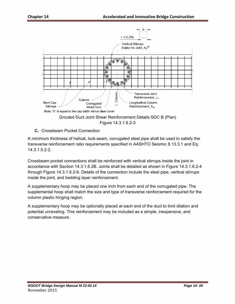
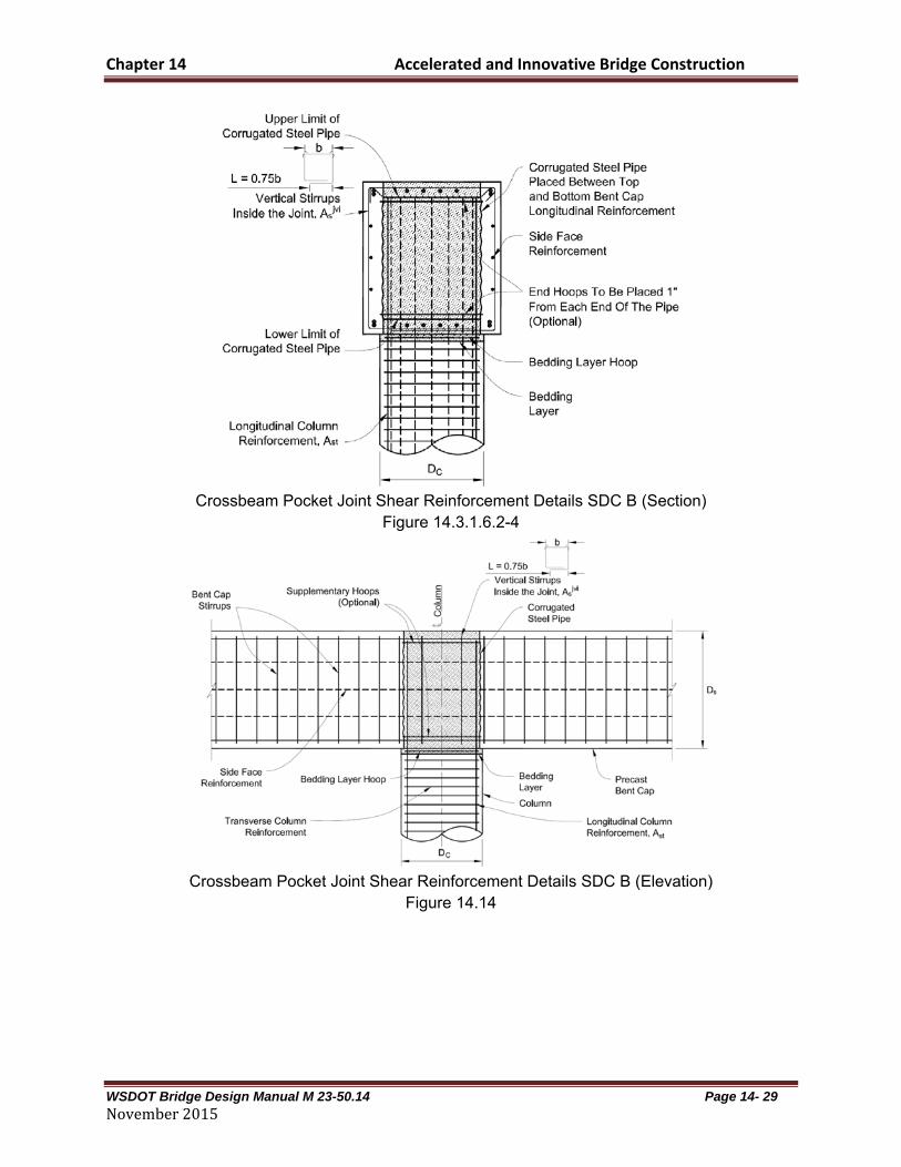
C. Crossbeam Pocket Connection
A minimum thickness of helical, lock-seam, corrugated steel pipe shall be used to satisfy the transverse reinforcement ratio requirements specified in AASHTO Seismic 8.13.3.1 and Eq. 14.3.1.5.2-2. Crossbeam pocket connections shall be reinforced with vertical stirrups inside the joint in accordance with Section 14.3.1.6.2B. Joints shall be detailed as shown in Figure 14.3.1.6.2-4 through Figure 14.3.1.6.2-6. Details of the connection include the steel pipe, vertical stirrups inside the joint, and bedding layer reinforcement.
A supplementary hoop may be placed one inch from each end of the corrugated pipe. The supplemental hoop shall match the size and type of transverse reinforcement required for the column plastic hinging region.
A supplementary hoop may be optionally placed at each end of the duct to limit dilation and potential unraveling. This reinforcement may be included as a simple, inexpensive, and conservative measure.
Chapter 14 Accelerated and Innovative Bridge Construction
WSDOT Bridge Design Manual M 23-50.14 Page 14- 29 November2015
Crossbeam Pocket Joint Shear Reinforcement Details SDC B (Section)
Figure 14.3.1.6.2-4
Crossbeam Pocket Joint Shear Reinforcement Details SDC B (Elevation)
Figure 14.14

Chapter 14 Accelerated and Innovative Bridge Construction
WSDOT Bridge Design Manual M 23-50.14 Page 14- 30 November2015
Crossbeam Pocket Joint Shear Reinforcement Details SDC B (Plan)
Figure 14.3.1.6.2-6
14.3.1.7 Joint Design for SDCs C and D Interior joints of multi-column bents shall be considered “T” joints for joint shear analysis. Exterior joints shall be considered knee joints and require special analysis and detailing that are not addressed herein, unless special analysis determines that “T” joint analysis is appropriate for an exterior joint based on the actual bent configuration. Criteria to establish appropriate design and detailing provisions for exterior joints shall be approved by the Bridge Design Engineer.
The HfL Bent System may only be used with Types 1, 3, 4, and 5 ERS as illustrated in AASHTO Seismic Figure 3.3-1a. The EREs permitted within the bent are Type 1, 2, 7, 8, and 13 as illustrated in AASHTO Seismic Figure 3.3-1b. No other EREs are permitted when the HfL bent is used.
Although the EREs are in the permissible category, the HfL bent system, itself, is only permissible with WSDOT Bridge Design Engineer’s approval.
The HfL Bent System has only been validated with spread footings, drilled shafts and plastic hinging restricted to the columns. Due to the limited application of the system, the EREs are all considered permissible with WSDOT Bridge Design Engineer’s approval. As experience is gained with the system this restriction may be eased.
The global design strategy of bridges that use the HfL bent system are expected to be Type 1 systems, because the validation has been conducted only on such systems. Type 3 systems could be designed using the bent system, although additional development effort would be required. The system as currently developed relies on a two-stage crossbeam that is integral with an open soffit girder superstructure. There is currently no configuration for a non-integral bent, which would be required with a Type 3 global design strategy.
Chapter 14 Accelerated and Innovative Bridge Construction
WSDOT Bridge Design Manual M 23-50.14 Page 14- 31 November2015
14.3.1.7.1 Local Displacement Capacity for SDCs B and C
AASHTO Seismic Equations 4.8.1-1, 2 and 3 may be used to assess the local displacement capacity of the HfL bent system in SDCs B and C. 14.3.1.7.2 Analytical Plastic Hinge Length
AASHTO Seismic Equations 4.11.6-1 and 3 apply to the HfL bent system without modification. The HfL bent system is an emulative system that behaves similarly to CIP systems of the same configuration. Validation testing reported by Pang, et.al (2008), Haraldsson, et.al. (2011), and Hung, et.al. (2012) has shown that the calculations of displacement capacity, including the analytical plastic hinge length and other elements of the procedure may be performed using the same approach as for CIP elements. 14.3.1.7.3 Joint Performance
Moment-resisting connections shall be designed to transmit the maximum forces produced when the column has reached its overstrength capacity, Mpo. 14.3.1.7.4 Joint Proportioning
Moment-resisting joints shall be proportioned so that the principal stresses satisfy the requirements of Eq. 8.13.2-1 and Equation 8.13.2-2.
A. Precast Crossbeam Connections
Column longitudinal reinforcement shall be extended into precast crossbeams as close as practically possible to the opposite face of the crossbeam. Column longitudinal bars should be extended into joints a sufficient depth to ensure the bars can achieve approximately 1.3 times the expected yield strength of the reinforcement. Compressive strength of the grout for grouted duct connections and compressive strength of the concrete fill for crossbeam pocket connections should be based on the requirements of Section 8.13.8.3 of the AASHTO LRFD Bridge Construction Specifications (2010).
B. Grouted Duct Connection
Grouted duct connections shall follow the requirements of AASHTO Seismic 8.13.3 for minimum transverse reinforcement in the joint. Spacing of transverse reinforcement shall not exceed 0.3Ds or 12 in. Where the principal tension stress in the joint, pt, as specified in AASHTO Seismic 8.13.2, is less than 0.11 (f’c)
0.5, then transverse reinforcement in the joint, ρs, shall satisfy AASHTO Seismic Eq. 8.13.3-1. Where the principal tension stress in the joint, pt, is greater than or equal to 0.11 (f’c)
0.5 , then transverse reinforcement in the joint, ρs, shall satisfy AASHTO Seismic Eq.

Chapter 14 Accelerated and Innovative Bridge Construction
WSDOT Bridge Design Manual M 23-50.14 Page 14- 32 November2015
8.13.3-2, and additional joint reinforcement is required as indicated in AASHTO Seismic 8.13.4 for integral crossbeams or AASHTO Seismic 8.13.5 for non-integral crossbeams. Where the principal tension stress in the joint, pt, is greater than or equal to 0.11 (f’c)
0.5, grouted duct connections shall be detailed to include additional joint shear reinforcement as specified in AASHTO Seismic 8.13.4 . In addition, vertical stirrups inside the joint shall consist of double leg stirrups or ties of a bar size no smaller than that of the crossbeam transverse reinforcement. A minimum of two stirrups or equivalent ties shall be used. Figure 14.3.1.7.4-1 through Figure 14.3.1.7.4-3 show details of the connection, including ducts, joint shear reinforcement, and bedding layer reinforcement assuming additional joint shear reinforcement is required. The grouted duct connection uses corrugated ducts embedded in the precast crossbeam to anchor individual column longitudinal bars. The ducts and bedding layer between the crossbeam and column or pile are grouted with high strength non-shrink cementitious grout to complete the precast connection. Ducts are sized to provide adequate tolerance for crossbeam fabrication and placement and must be accounted for in sizing the crossbeam to minimize potential congestion.
Joint shear reinforcement requirements are essentially the same as for cast-in-place connections, except that minimum vertical stirrups are required in the joint where the principal tension stress in the joint, pt, is less than 0.11 (f’c)
0.5 per AASHTO Seismic 8.13.3.
Grouted Duct Full Ductility Joint Shear Reinforcement Details SDC C and D (Section)
Figure 14.3.1.7.4-1

Chapter 14 Accelerated and Innovative Bridge Construction
WSDOT Bridge Design Manual M 23-50.14 Page 14- 33 November2015
Grouted Duct Full Ductility Joint Shear Reinforcement Details SDC C and D (Elevation)
Figure 14.3.1.7.4-2
Grouted Duct Full Ductility Joint Shear Reinforcement Details SDC C and D (Plan)
Figure 14.3.1.7.4-3
C. Crossbeam Pocket Connection
Crossbeam pocket connections shall use a helical, lock seam, corrugated steel pipe to form the crossbeam pocket. The thickness of the corrugated pipe shall be sized to satisfy transverse reinforcement ratio requirements specified in AASHTO Seismic 8.13.3.1.
Chapter 14 Accelerated and Innovative Bridge Construction
WSDOT Bridge Design Manual M 23-50.14 Page 14- 34 November2015
A supplementary hoop shall be placed one inch from each end of the corrugated pipe. The supplemental hoop shall match the size and type of transverse reinforcement required for the column plastic hinging region.
A minimum thickness of helical, lock-seam, corrugated steel pipe shall be used to satisfy the transverse reinforcement ratio requirements specified in AASHTO Seismic 8.13.3.1 and Eq. 14.3.1.5.2-2. The thickness of the corrugated steel pipe is intended to provide an average confining hoop force to the joint approximately the same as that provided by hoops required for cast-in-place construction. The minimum thickness of the steel pipe, of 0.0598 in. corresponds to 16 gage steel pipe, which was used in the supporting precast crossbeam research and is the thinnest gage steel corrugated pipe that is typically available.
Non-integral crossbeam systems addressed in this Section use connections between the crossbeam and column that are classified as either cast-in-place or emulative precast. Emulative precast crossbeam-to-column connections are designed and detailed to emulate joint performance and system ductility achieved by monolithic, cast-in-place construction. Emulative systems use cast-in-place concrete or grout to join the precast crossbeam to the column. Associated construction specifications are detailed in AASHTO LRFD Bridge Construction Specifications, Section 8.13.8 (2010).
Cast-in-place and emulative precast crossbeam-to column joints are designed to accommodate the forces associated with the column’s overstrength plastic hinging moment capacity in an essentially elastic manner.
Vertical stirrup requirements are more conservative for non-integral crossbeam systems than for integral crossbeam systems. For example, stirrups outside the joint region that are required for the force transfer mechanism may not simultaneously be used to resist other design requirements such as crossbeam shear due to dead, live, and earthquake loads.
D. Joint Shear Reinforcement
Where the principal tension stress in the joint, pt, is greater than or equal to 0.11 f'c, crossbeam pocket connections shall be detailed to include additional joint shear reinforcement as specified in AASHTO Seismic 8.13.4 and 8.13.5.
Vertical stirrups inside the joint shall consist of double leg stirrups or ties of a bar size no smaller than that of the crossbeam transverse reinforcement. A minimum of two stirrups or equivalent ties shall be used.
The crossbeam pocket connection uses a single, helical, corrugated steel pipe embedded in the crossbeam to form the crossbeam pocket, which anchors column longitudinal bars.
This pipe, placed between crossbeam longitudinal reinforcement, serves both as a stay-in-place form and as well as joint transverse reinforcement, the hoops. The duct diameter is sized to provide adequate tolerance for crossbeam placement over column longitudinal bars, and the duct thickness is sized to satisfy transverse joint reinforcement requirements.
Chapter 14 Accelerated and Innovative Bridge Construction
WSDOT Bridge Design Manual M 23-50.14 Page 14- 35 November2015
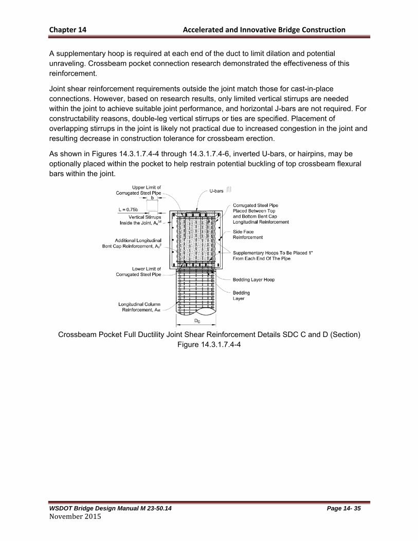
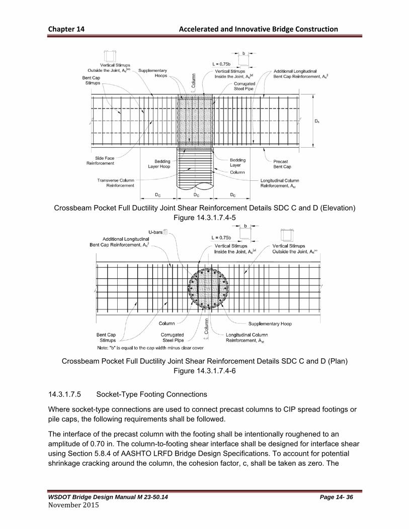
A supplementary hoop is required at each end of the duct to limit dilation and potential unraveling. Crossbeam pocket connection research demonstrated the effectiveness of this reinforcement.
Joint shear reinforcement requirements outside the joint match those for cast-in-place connections. However, based on research results, only limited vertical stirrups are needed within the joint to achieve suitable joint performance, and horizontal J-bars are not required. For constructability reasons, double-leg vertical stirrups or ties are specified. Placement of overlapping stirrups in the joint is likely not practical due to increased congestion in the joint and resulting decrease in construction tolerance for crossbeam erection.
As shown in Figures 14.3.1.7.4-4 through 14.3.1.7.4-6, inverted U-bars, or hairpins, may be optionally placed within the pocket to help restrain potential buckling of top crossbeam flexural bars within the joint.
Crossbeam Pocket Full Ductility Joint Shear Reinforcement Details SDC C and D (Section)
Figure 14.3.1.7.4-4
Chapter 14 Accelerated and Innovative Bridge Construction
WSDOT Bridge Design Manual M 23-50.14 Page 14- 36 November2015
Crossbeam Pocket Full Ductility Joint Shear Reinforcement Details SDC C and D (Elevation)
Figure 14.3.1.7.4-5
Crossbeam Pocket Full Ductility Joint Shear Reinforcement Details SDC C and D (Plan) Figure 14.3.1.7.4-6
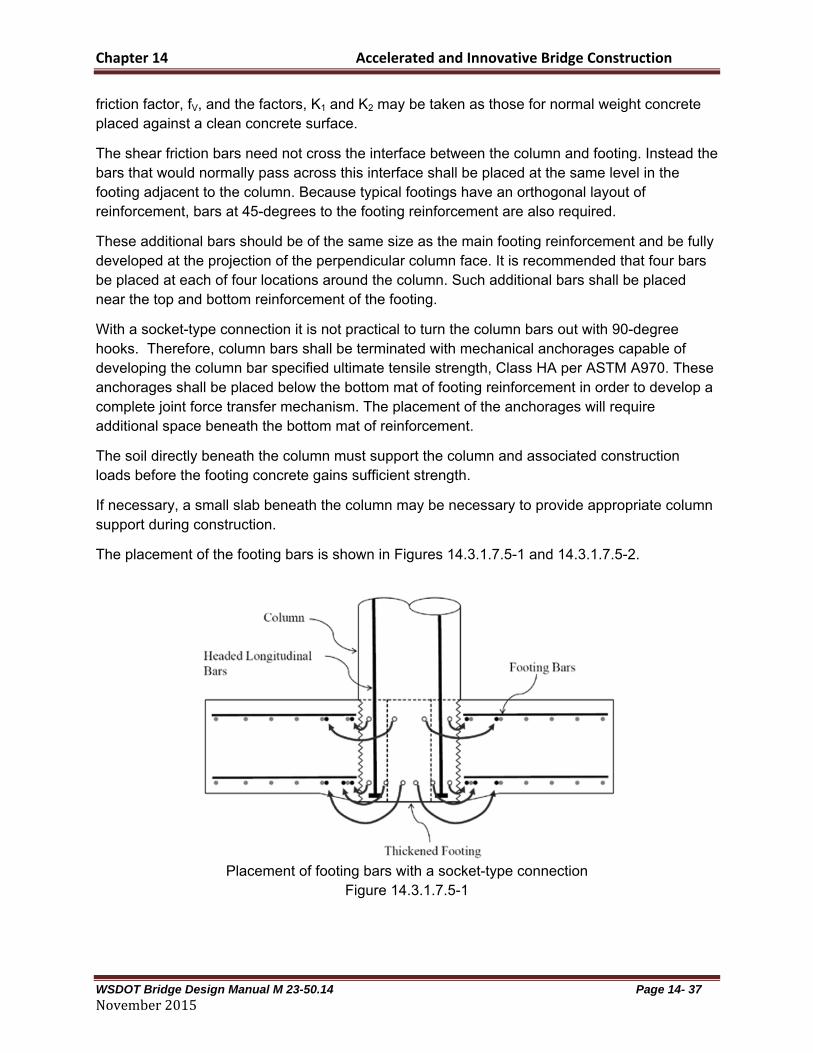
14.3.1.7.5 Socket-Type Footing Connections
Where socket-type connections are used to connect precast columns to CIP spread footings or pile caps, the following requirements shall be followed.
The interface of the precast column with the footing shall be intentionally roughened to an amplitude of 0.70 in. The column-to-footing shear interface shall be designed for interface shear using Section 5.8.4 of AASHTO LRFD Bridge Design Specifications. To account for potential shrinkage cracking around the column, the cohesion factor, c, shall be taken as zero. The
Chapter 14 Accelerated and Innovative Bridge Construction
WSDOT Bridge Design Manual M 23-50.14 Page 14- 37 November2015
friction factor, fV, and the factors, K1 and K2 may be taken as those for normal weight concrete placed against a clean concrete surface.
The shear friction bars need not cross the interface between the column and footing. Instead the bars that would normally pass across this interface shall be placed at the same level in the footing adjacent to the column. Because typical footings have an orthogonal layout of reinforcement, bars at 45-degrees to the footing reinforcement are also required.
These additional bars should be of the same size as the main footing reinforcement and be fully developed at the projection of the perpendicular column face. It is recommended that four bars be placed at each of four locations around the column. Such additional bars shall be placed near the top and bottom reinforcement of the footing.
With a socket-type connection it is not practical to turn the column bars out with 90-degree hooks. Therefore, column bars shall be terminated with mechanical anchorages capable of developing the column bar specified ultimate tensile strength, Class HA per ASTM A970. These anchorages shall be placed below the bottom mat of footing reinforcement in order to develop a complete joint force transfer mechanism. The placement of the anchorages will require additional space beneath the bottom mat of reinforcement.
The soil directly beneath the column must support the column and associated construction loads before the footing concrete gains sufficient strength.
If necessary, a small slab beneath the column may be necessary to provide appropriate column support during construction.
The placement of the footing bars is shown in Figures 14.3.1.7.5-1 and 14.3.1.7.5-2.
Placement of footing bars with a socket-type connection
Figure 14.3.1.7.5-1

Chapter 14 Accelerated and Innovative Bridge Construction
WSDOT Bridge Design Manual M 23-50.14 Page 14- 38 November2015
Placement of additional bars at 45° to main footing reinforcement
Figure 14.3.1.7.5-2
14.3.1.7.6 Precast Column
Precast columns and crossbeams that are used with the HfL bent system are covered by AASHTO Seismic 8. The columns of such systems are not considered precast concrete piles.
A. Interface Shear Transfer Capacity of Precast Bent Systems
The interface shear capacity between precast column and crossbeam or between segments of precast columns shall be determined using Section 5.8.4 of AASHTO LRFD Bridge Design Specifications. To account for cyclic loading effects and the potential for significant cracking, the
cohesion factor, c, shall be taken as zero and the friction factor, , shall be 0.60. The factors, K1 and K2 shall be 0.2 and 0.8 ksi, respectively.
B. Splicing of Longitudinal Reinforcement in Columns Subject to Ductility Demands for SDCs C and D
Where tensile force is transferred between reinforcing anchored into steel ducts using high
strength grout and bars adjacent to the duct, the splice length, lsplice, shall be the longer of the anchorage length of the bar inside the duct, as given by Section 14.3.1.7.6C or the splice length of the bars on the outside of the duct as determined by Article 5.11.5 of AASHTO LRFD Bridge Design Specifications.
To the extent practical, the bars spliced to the duct should be arranged to minimize eccentricity and should be in contact with the duct. If bars are placed away from the duct, the non-contact distance must be added to the splice length.
Transverse steel shall enclose both the duct and the bars outside the duct as shown in Figure 14.3.1.7.6-1.

Chapter 14 Accelerated and Innovative Bridge Construction
WSDOT Bridge Design Manual M 23-50.14 Page 14- 39 November2015
Splicing of Grouted Duct Bars to Other Bars
Figure 14.3.1.7.6-1
C. Minimum Development Length of Reinforcing Steel for SDCs C and D
The anchorage length for column bars developed into steel ducts shall satisfy:
g
yehtac
f
fdl
'
67.0 Equation 14.3.1.7.6-1
Where: dht = diameter of longitudinal column bar (in) fye = expected yield stress of the longitudinal reinforcement (ksi) f’g = nominal compressive strength of the grout (ksi)
When bars are anchored into steel ducts, the force that is transferred to the duct must then be transferred to adjacent reinforcement. In addition to the development length provided in Equation 14.3.1.7.6-1, the length of the embedment must consider the splice length required and configuration, for example the non-contact distance, of the bars outside of the duct, to which the tensile force is transferred. The ducts used shall be steel and be of semi-rigid corrugated construction. Axial force shall not be transferred beyond the end of the bar anchored within the duct without testing to demonstrate that the duct has the capacity to withstand the expected tensile force.
In the case of dropped crossbeams, where ducts anchor column reinforcement in the first or lower stage crossbeam, but the superstructure is integral with the upper diaphragm, all column bars must extend into the upper diaphragm. These bars should extend as far as practical to the top of the upper crossbeam.
In the event that a limited number of column bars need to be terminated in the lower crossbeam, a rational analysis, such as strut-and-tie analysis, shall be conducted to account for the actual distribution of forces transferred from the column bars to the crossbeam.

Chapter 14 Accelerated and Innovative Bridge Construction
WSDOT Bridge Design Manual M 23-50.14 Page 14- 40 November2015
The length of the duct used to anchor grouted bars may be controlled by either the bar grouted into the duct, as provided by Equation 14.3.1.7.6-1, or the normal splice length of the bars on the outside of the duct.
Additionally, if such bars are not adjacent to the duct, then the non-contact distance should be added to the splice length.
Testing by Eberhard et.al. (2009) showed that large reinforcing bars can be developed in shorter lengths than normal, if the bars are grouted into steel ducts. The bars can develop their ultimate strength if grouted at least 16 bar diameters into the ducts. This length allows for cyclic degradation and is based on developing at least 95 ksi bar stress with grout strengths of 8 ksi. Eq. 14.3.1.7.6-1 provides adjustment for grout strength and assumes the ultimate strength of the bar is 1.4 times the expected yield strength.
For smaller applications, corrugated post-tensioning duct is adequate. For anchorage of larger bars, corrugated steel pipe conforming to ASTM A760 may be used. Such pipe should be galvanized.
The ducts are intended to provide local confinement, crack arresting, and provide a roughened surface to facilitate shear transfer from the bar anchored inside to the adjacent concrete. The ducts are not intended to resist tensile forces.
Because the joint shear force transfer between the vertical system and superstructure takes place in the upper crossbeam, the column bars must be extended into the upper crossbeam. The effect of the lower crossbeam is to distribute forces along the crossbeam and thereby enlarge the effective joint shear region.
D. Lateral Reinforcement Inside the Plastic Hinge Region for SDCs C and D
Where precast columns connected with grouted bedding layers are used, lateral reinforcement may be required within the bedding layer. The maximum spacing of lateral reinforcement applies inclusive of the bedding layer. Lateral reinforcement included in the bedding layer shall be of the same size as that in the column itself. If stronger materials are used for reinforcement of the bedding layer, the assumed material strength for design shall be the same as that used for the column.
If cross slope results in a varying thickness of the grout bedding layer, the largest thickness shall be used to configure the lateral reinforcement.
E. Development Length for Column Bars Extended into Oversized Drilled Shafts for SDCs C and D
Where socket connections are used, column bars may be terminated with straight bar embedment or mechanical anchorages capable of developing the column bar specified ultimate tensile strength per Class HA per ASTM A970.
All column bars may be terminated at the same location, provided the confinement steel required in Section 14.3.1.7.7A is included.

Chapter 14 Accelerated and Innovative Bridge Construction
WSDOT Bridge Design Manual M 23-50.14 Page 14- 41 November2015
The bars shall be extended into the transition or splice zone of the pile shaft. The embedment depth shall meet the requirements of Section 7.4.4C. The embedment depth shall also include the total bar end cover distance of both column and shaft bars.
14.3.1.7.7 Drilled Shaft
Where socket-type connections are used to connect precast columns to drilled shafts the column-to-shaft side interface shall be intentionally roughened to an amplitude of 0.70 in. Because axial loads can be supported by end bearing of the column on the shaft, a shear friction interface design is not required. However, consideration shall be given to temporary support of the precast column and to proper consolidation of concrete between the column base and shaft to ensure that an adequate load path is provided.
A. Lateral Confinement for Oversized Drilled Shafts for SDCs C and D
Where socket connections of precast columns are used to connect columns with drilled shafts, adequate confinement reinforcement must be included to react the internal tension forces that develop. Lateral confinement reinforcement along the column embedment length shall satisfy Section 7.8.2K.
The confinement reinforcement requirements over the top portions of oversized pile shafts that connect with precast columns are included to provide tie reinforcement to resist prying forces introduced near the top of the shaft by the precast column.
Experimental testing by Hung, et. al. 2013 has shown that adequate strength may be achieved in such connections, provided the lateral confinement reinforcement as defined by Eq. 7.8.2-1 is included. The additional confinement reinforcement required over the upper half of the embedment length is intended to limit potential shaft damage, which tends to occur at the top of the shaft if adequate confinement is not provided. 14.3.1.7.8 Superstructure Capacity Design for Integral Crossbeams for Longitudinal
Direction for SDCs C and D
The effective width of open-soffit superstructure resisting longitudinal seismic moments, Beff, may be determined by Equation 14.3.1.7.8-1 for open soffit, girder deck superstructures supported on dropped crossbeam integral bents.
212 SSCeff DDDB Equation 14.3.1.7.8-1
Where: DC = diameter of the column (in.) DS1 = depth of dropped portion of crossbeam (in.) DS2 = depth of superstructure (in.)
Where the superstructure frames into the integral crossbeam, adequate reinforcement from the superstructure must extend into the crossbeam in order to transmit the capacity protection forces that are expected. This implies that both top and bottom reinforcement must extend into

Chapter 14 Accelerated and Innovative Bridge Construction
WSDOT Bridge Design Manual M 23-50.14 Page 14- 42 November2015
the crossbeam or diaphragm. This reinforcement must lap with similar reinforcement from the opposite side of the diaphragm such that a complete load path for equilibrium of moments is provided. For the case of a dropped crossbeam that is integral with an upper diaphragm located within the depth of the superstructure, additional lateral distribution of longitudinal moment will occur by virtue of the additional crossbeam depth, and increased torsional capacity of the combined upper diaphragm and lower crossbeam. The two stages of crossbeam construction must be integral over the full width of the crossbeam and closed torsional stirrups and longitudinal steel must be present in the crossbeam to distribute the induced torsional forces.
14.3.1.7.9 Integral Crossbeam
A. Joint Proportioning
Where integral dropped crossbeam construction is used, calculation of the average horizontal, vertical and joint shear stresses for longitudinal loading shall use the following approach: In the transverse direction, Ds shall be taken as the full depth of the combined lower and upper stages of the crossbeam.
In the longitudinal direction, the following equations shall be used, in lieu of AASHTO Seismic Equations. 8.13.2-5 through 8.13.2-7.
For an integral dropped crossbeam, the average horizontal stress, fh, shall be taken as:
)2( 212 SSCS
bh DDDD
Pf
Equation 14.3.1.7.9-1
Where:
DC = diameter of the column (in.) DS1 = depth of dropped portion of crossbeam (in.) DS2 = depth of superstructure (in.) Pb = superstructure axial force at the center of the joint including effects of prestressing (kip)
For an integral dropped crossbeam, the average vertical stress, fV, shall be taken as:
)2( 21 SSCcap
CV DDDB
Pf
Equation 14.3.1.7.9-2
Where:
PC = column axial force (kips) Bcap = crossbeam width (in)
Chapter 14 Accelerated and Innovative Bridge Construction
WSDOT Bridge Design Manual M 23-50.14 Page 14- 43 November2015
B. Dropped Crossbeam
For an integral dropped crossbeam, the average joint shear stress, vjv, shall be taken as:
)2( 21 SScac
cjv DDDl
Tv
Equation 14.3.1.7.9-3
Where:
TC = column tensile force associated with column overstrength plastic hinging moment, Mpo (kips)
lac= length of column and additional effective crossbeam reinforcement embedded into upper stage, DS2, of crossbeam (in)
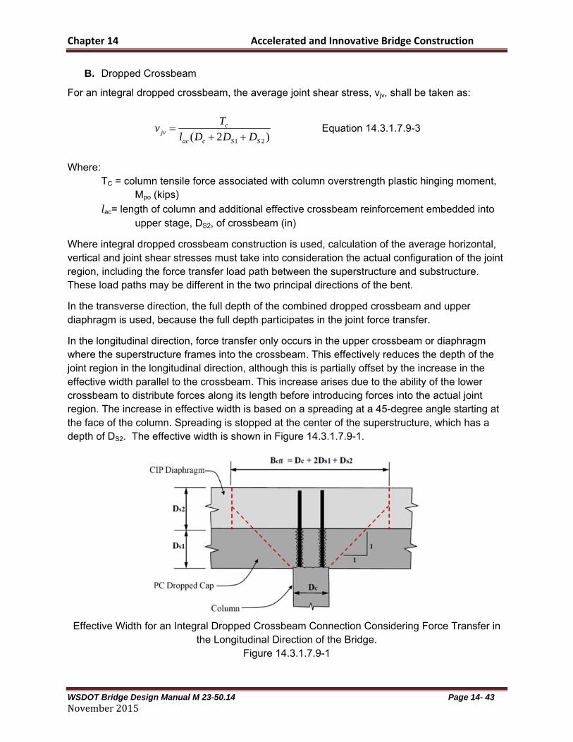
Where integral dropped crossbeam construction is used, calculation of the average horizontal, vertical and joint shear stresses must take into consideration the actual configuration of the joint region, including the force transfer load path between the superstructure and substructure. These load paths may be different in the two principal directions of the bent.
In the transverse direction, the full depth of the combined dropped crossbeam and upper diaphragm is used, because the full depth participates in the joint force transfer.
In the longitudinal direction, force transfer only occurs in the upper crossbeam or diaphragm where the superstructure frames into the crossbeam. This effectively reduces the depth of the joint region in the longitudinal direction, although this is partially offset by the increase in the effective width parallel to the crossbeam. This increase arises due to the ability of the lower crossbeam to distribute forces along its length before introducing forces into the actual joint region. The increase in effective width is based on a spreading at a 45-degree angle starting at the face of the column. Spreading is stopped at the center of the superstructure, which has a depth of DS2. The effective width is shown in Figure 14.3.1.7.9-1.
Effective Width for an Integral Dropped Crossbeam Connection Considering Force Transfer in
the Longitudinal Direction of the Bridge. Figure 14.3.1.7.9-1

Chapter 14 Accelerated and Innovative Bridge Construction
WSDOT Bridge Design Manual M 23-50.14 Page 14- 44 November2015
The effective reinforcement in the upper crossbeam joint region is that column reinforcement that extends into the upper diaphragm and the crossbeam stirrups and other bars that extend from the lower crossbeam into the upper diaphragm over the effective width of the longitudinal joint shear region, DC+2DS1+DS2.
The column tensile force is calculated using AASHTO Seismic Equation 8.13.2-8.
C. Minimum Joint Shear Reinforcing
When grouted ducts are used, transverse reinforcement shall be included around the ducts that anchor column reinforcement. The transverse reinforcement in the joint shall satisfy AASHTO Seismic Equations 8.13.3-1 and 8.13.3-2 and applicable requirements of AASHTO Seismic 8.13.4 and 8.13.5.
D. T Joints
The provisions in this article apply to integral dropped crossbeam construction. The required vertical stirrups, Ajv, shall extend of the full depth of the crossbeam.
E. Knee Joints
The provisions in this article apply to integral dropped crossbeam construction. The required vertical stirrups, Ajv, shall extend of the full depth of the crossbeam. The full depth of the integral crossbeam, DS1+DS2, shall be considered when laying out the required additional reinforcement.
F. Horizontally Isolated Flares
Where precast column segments are larger than the interface and bedding layer connecting to the crossbeam, the requirements for horizontally isolated flares shall apply.
The design of such systems should include both the geometry of the bedding layer and any length of column that is similarly reduced in cross section. The combined length of these defines the gap thickness. 14.3.2 Geosynthetic Reinforced Soil Integrated Bridge System
The GRS-IBS method has been used for supporting bridge abutments increasingly around the country with success. The FHWA has developed a manual for this type of bridge abutment, provided on the following FHWA website:
http://www.fhwa.dot.gov/everydaycounts/technology/grs_ibs/
Proprietary SE walls supporting abutments shall not be considered preapproved, and shall not be used beyond the limits described herein unless approved by the WSDOT State Geotechnical Engineer and the WSDOT Bridge Design Engineer.
See Section 7.5.11 for design requirements of abutments supported on reinforced soil walls. 14.3.3 Precast Decks

Chapter 14 Accelerated and Innovative Bridge Construction
WSDOT Bridge Design Manual M 23-50.14 Page 14- 45 November2015
Full-depth precast bridge deck systems consist of the precast panels, grout between the supporting girder and the precast panel, temporary support and forms along the girder to retain the grout, pockets or block-outs to accommodate the shear connections to the girder, transverse joints between the precast panels and some type of overlay to provide for rideability. Longitudinal post-tensioning may also be included in the system. A full-depth precast deck consists of a series of precast concrete panels that are full depth in thickness with the length and width determined by specific bridge geometry. The length along the roadway is approximately 8 to 12 feet and a width equal to the full bridge width or half bridge width for wide bridges (greater than 50 feet). Panels span between the supporting girders and are designed as reinforced or prestressed concrete using pretensioning or post-tensioning. The general preference of contractors is to use prestressed concrete to eliminate possible cracking from handling and shipping. See Figures 14.3.3-1 and 14.3.3-2 for typical layout of a precast deck.
Typical Plans for Square Panel Figure 14.3.3-1

Chapter 14 Accelerated and Innovative Bridge Construction
WSDOT Bridge Design Manual M 23-50.14 Page 14- 46 November2015
Typical Plans for Skewed Panel
Figure 14.3.3‐2
The panels can be designed for composite or non-composite action with the supporting girders. A non-composite design is much simpler and easier to fabricate because of the elimination of the shear connections which complicate forming the panel and require special placement of shear reinforcement or studs and restricts post-tensioning operations. The benefits of precast full depth deck systems include improved quality, reduced construction time or impact on traveling public, possible weight reduction and reduction of total project cost. Because the precast deck system is produced in a plant environment, the quality is superior to field cast concrete bridge decks. The variability of construction due to environmental conditions can be easily accommodated in a plant with consistency to minimize negative impact on the casting operations and deck quality. The size of casting units is smaller thereby reducing the mix, placing and finishing variability that exists in the field. Also, because the units are small, curing can be easily controlled and applied as soon as possible to achieve the best material performance characteristics. High performance concrete (HPC) is recommended for all bridge decks and requires quality construction practices to achieve the best performance characteristics. Plant casting provides greater assurance that the performance characteristics of HPC will be achieved. This issue becomes more critical as available field labor decreases or labor turnover for contractors continues.

Chapter 14 Accelerated and Innovative Bridge Construction
WSDOT Bridge Design Manual M 23-50.14 Page 14- 47 November2015
Many projects constructed using full-depth precast deck panels have demonstrated a significant reduction in construction time, impact on the traveling public or impact on peak traffic flow. The construction time reduction has been documented to be from 50 to 75 % of the time required for cast-in-place bridge deck construction. The demonstrated construction time savings meets the public’s demand for faster construction and less impact to traffic. The reduced construction time also reduces the safety hazards to motorists and workers by reducing the total time they are exposed to the work zone. Successful projects using full-depth precast deck systems have also shown flexibility for accommodating the peak traffic flows for projects in high traffic urban locations. The projects demonstrate the ability to replace decks during non peak traffic and have the full roadway open for peak traffic. This can be accomplished with night only work, weekend only work, or other non-peak traffic period work. A great advantage provided by precast full-depth bridge deck panels is that the panel construction is removed from the critical path and can be fabricated prior to need at he project site for installation. For bridge construction, this will generally remove a considerable amount of work from the critical path and permit construction to be completed earlier. Also, precast components can significantly remove the amount of work required to be competed at the job site and reduces the risk to traffic and worker safety. This provides greater flexibility in establishing the project schedule and allows concentration by the contractor on the critical path items. Another advantage provided by full-depth precast bridge deck panels is the ability to reduce the dead load with the use of lightweight concrete. Although, the same weight reduction can be achieved for cast-in-place decks through use of lightweight concrete, the precast plant environment makes the use of lightweight concrete more desirable. The complexities of mixing, placing, finishing and curing lightweight concrete are simplified and easier to accommodate in a plant environment. The majority of precast plants provide central mix operation, shorter haul times, shorter placement times, quicker finishing times and quicker application of curing. All of these items have an impact on the successful use of lightweight concrete and the probability of success is significantly greater in the plant environment.
14.4 Innovative Bridge Construction
Innovative Bridge Construction is simply an idea that encourages outside the box thinking encouraging engineers to consider principles that will enhance bridge performance, speed up construction, or add any other benefit to the industry. There is no single or handful of ideas that can contain or describe Innovative Bridge Construction. It’s simply a mentality that new ideas ought to be explored. Innovation might be defined as any contribution to the bridge industry that takes bridge construction past the current standard practice of bridge construction. Some items produced recently are described in the following sections. 14.4.1 Self-Centering Columns
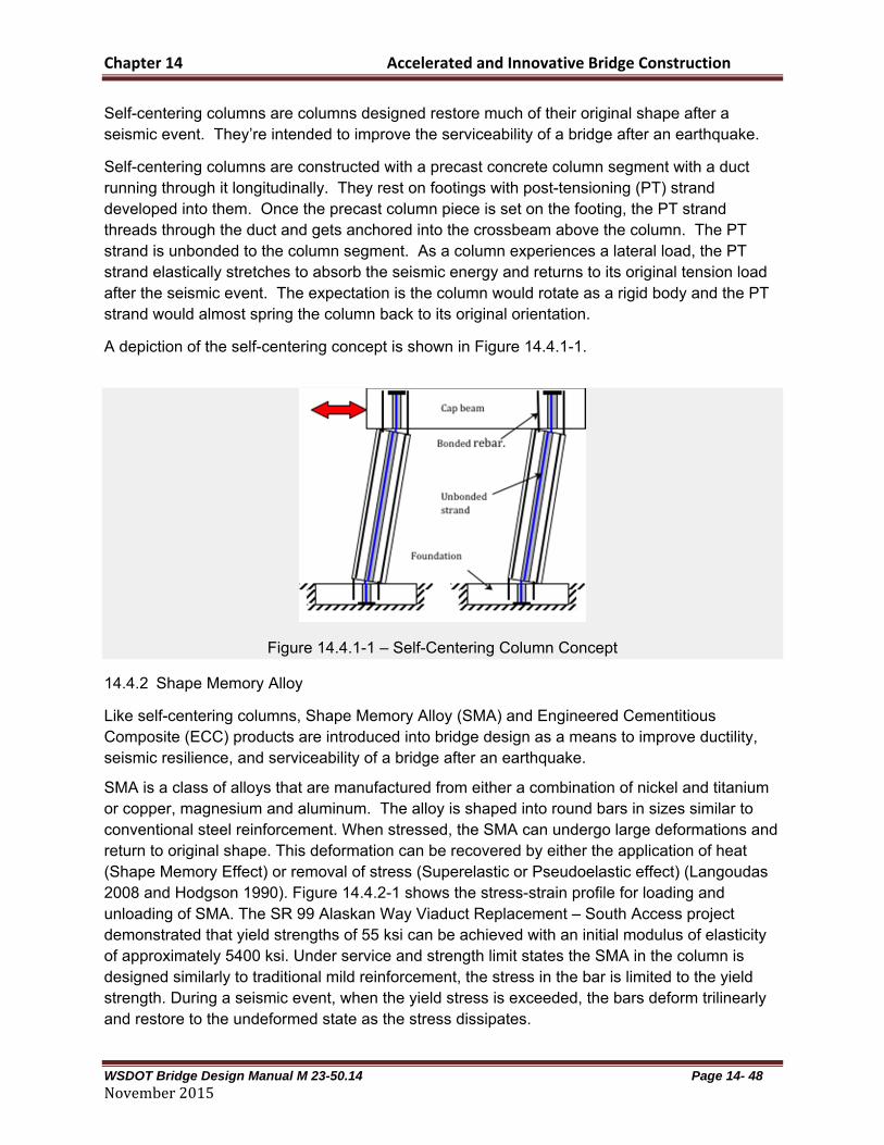
Chapter 14 Accelerated and Innovative Bridge Construction
WSDOT Bridge Design Manual M 23-50.14 Page 14- 48 November2015
Self-centering columns are columns designed restore much of their original shape after a seismic event. They’re intended to improve the serviceability of a bridge after an earthquake.
Self-centering columns are constructed with a precast concrete column segment with a duct running through it longitudinally. They rest on footings with post-tensioning (PT) strand developed into them. Once the precast column piece is set on the footing, the PT strand threads through the duct and gets anchored into the crossbeam above the column. The PT strand is unbonded to the column segment. As a column experiences a lateral load, the PT strand elastically stretches to absorb the seismic energy and returns to its original tension load after the seismic event. The expectation is the column would rotate as a rigid body and the PT strand would almost spring the column back to its original orientation.
A depiction of the self-centering concept is shown in Figure 14.4.1-1.
Figure 14.4.1-1 – Self-Centering Column Concept
14.4.2 Shape Memory Alloy
Like self-centering columns, Shape Memory Alloy (SMA) and Engineered Cementitious Composite (ECC) products are introduced into bridge design as a means to improve ductility, seismic resilience, and serviceability of a bridge after an earthquake.
SMA is a class of alloys that are manufactured from either a combination of nickel and titanium or copper, magnesium and aluminum. The alloy is shaped into round bars in sizes similar to conventional steel reinforcement. When stressed, the SMA can undergo large deformations and return to original shape. This deformation can be recovered by either the application of heat (Shape Memory Effect) or removal of stress (Superelastic or Pseudoelastic effect) (Langoudas 2008 and Hodgson 1990). Figure 14.4.2-1 shows the stress-strain profile for loading and unloading of SMA. The SR 99 Alaskan Way Viaduct Replacement – South Access project demonstrated that yield strengths of 55 ksi can be achieved with an initial modulus of elasticity of approximately 5400 ksi. Under service and strength limit states the SMA in the column is designed similarly to traditional mild reinforcement, the stress in the bar is limited to the yield strength. During a seismic event, when the yield stress is exceeded, the bars deform trilinearly and restore to the undeformed state as the stress dissipates.
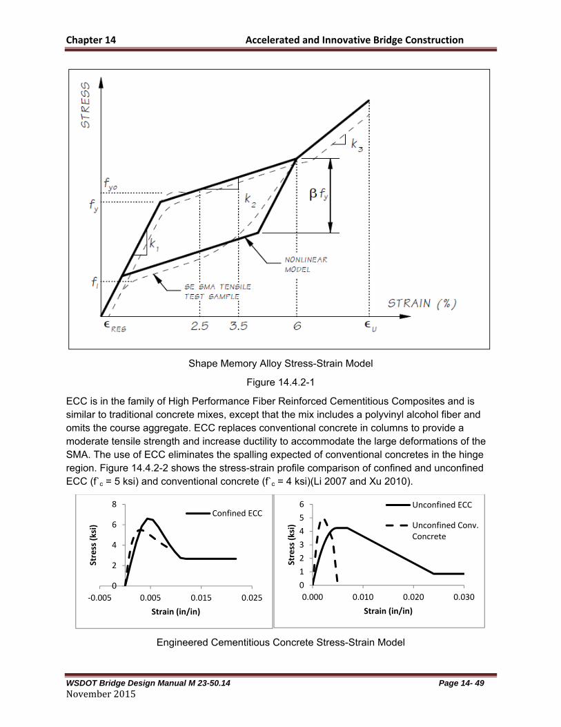
Chapter 14 Accelerated and Innovative Bridge Construction
WSDOT Bridge Design Manual M 23-50.14 Page 14- 49 November2015
Shape Memory Alloy Stress-Strain Model
Figure 14.4.2-1
ECC is in the family of High Performance Fiber Reinforced Cementitious Composites and is similar to traditional concrete mixes, except that the mix includes a polyvinyl alcohol fiber and omits the course aggregate. ECC replaces conventional concrete in columns to provide a moderate tensile strength and increase ductility to accommodate the large deformations of the SMA. The use of ECC eliminates the spalling expected of conventional concretes in the hinge region. Figure 14.4.2-2 shows the stress-strain profile comparison of confined and unconfined ECC (f`c = 5 ksi) and conventional concrete (f`c = 4 ksi)(Li 2007 and Xu 2010).
Engineered Cementitious Concrete Stress-Strain Model
0
2
4
6
8
‐0.005 0.005 0.015 0.025
Stress (ksi)
Strain (in/in)
Confined ECC
0
1
2
3
4
5
6
0.000 0.010 0.020 0.030
Stress (ksi)
Strain (in/in)
Unconfined ECC
Unconfined Conv.Concrete

Chapter 14 Accelerated and Innovative Bridge Construction
WSDOT Bridge Design Manual M 23-50.14 Page 14- 50 November2015
Figure 14.4.2-2
When combined in the plastic hinge zones of bridge columns, the SMA and ECC materials are designed to provide high levels of strain with a super-elastic performance to allow for large deflections with negligible permanent deformation and minimal damage. This combination of materials provides the ductility a bridge column needs to perform well in a seismic event while providing enough elasticity to restore the bridge closer to its original shape than conventional concrete and rebar, even with proper detailing (Cruz 2012).
Bars fabricated with SMA are coupled with conventional steel reinforcing located outside the plastic hinge region to reduce the amount of SMA used in the bridge column. The engineered cementitious material can be poured within the plastic hinge region separately from the rest of the column concrete.
An example of a column with ECC and SMA reinforcing in the plastic hinge regions is shown in Figure 14.4.2-3.
Shape Memory Alloy and Engineered Cementitious Column (Elevation and Sections)
Figure 14.4.2-3
14.5 Shipping, Handling and Erection
14.5.1 Lifting Devices
Lifting locations for precast elements shall be shown in the design plans. The engineer is responsible for checking the handling stresses in the element for the lifting locations shown on the plans. Elements shall be designed using the following general criteria:
Chapter 14 Accelerated and Innovative Bridge Construction
WSDOT Bridge Design Manual M 23-50.14 Page 14- 51 November2015
For stripping from the form, use two point picks for columns and pier crossbeams, similar to prestressed beams. Columns will require additional pick points for tripping into the vertical orientation during erection. Wall panels generally require four or more pick points when lifting horizontal and additional pick points for tipping into the vertical orientation during erection.
Use an allowable stress of cf 16.0 on the static tensile stress in the concrete during
handling. This is typical in the industry and provides a 50% buffer against exceeding the modulus of rupture during handling.
Do not show specific lifting hardware on the drawings. Verify that at least one lifting hardware manufacturer can provide a device that can resist the anticipated loads. Consider reducing the size of the element or switch to a more sophisticated lifting system if no manufacturer can meet the required resistance. Consult with fabricators for these situations.
The contractor may choose alternate lifting locations with approval from the engineer. The contractor will provide the spacing and location of the lifting devices and submit plan and handling stress calculations for approval prior to construction of the element. Unless buried in a subsequent cast-in-place concrete pour, lifting devices shall be recessed a minimum of 1” below the exposed surface of the precast element. Recesses at the lifting devices shall have a roughened finish. Some recesses are formed and cannot be broomed during finishing. In those cases a surface retarder can be used to provide a roughened surface. After the element is placed in its final position, The lifting device shall be removed to the base of the recess and the recess shall be filled with structural non-shrink grout or other approved patching material. In some cases the recess may be on a vertical surface and non-shrink grout may not be feasible. 14.5.2 Handling and Storage
The contractor is responsible for the handling and storage of precast elements in such a manner that does not cause undue stress on the element. The contractor shall submit a handling and storage plan to the engineer for review prior to the construction of any element.
The engineer will inspect all elements and reject any elements with defects that are not considered repairable. The rejected elements will be replaced at the contractor’s expense. The contractor is responsible for any schedule delays due to rejected elements. 14.5.3 Tolerances
The tolerance of casting elements is critical to a successful installation. One of the most important tolerances is the location of the grouted duct splices. Make the dimension measurements from a common working point or line in order to specify tolerances of critical elements. Templates shall be used where practical. Center to center measurements can lead to a build-up of tolerance errors.
The typical detail drawings shall include details of maximum allowable tolerances. Include these details in all precast substructure projects.

Chapter 14 Accelerated and Innovative Bridge Construction
WSDOT Bridge Design Manual M 23-50.14 Page 14- 52 November2015
Include a requirement in the project specifications that, unless templates are used to the satisfaction of the engineer. Note that erection tolerances are also extremely important, especially with placement of the crossbeam on multiple columns prior to installation of the elements at the bridge site. This is especially true for grouted splice couplers. Verify the spacing of the couplers as well as their orientation within the element. The splice reinforcement is often left longer than required in the fabrication yard so that the bars can be cut the exact length in the field as the construction progresses. The dry fit can still be done in this case with the longer bars. 14.5.4 Assembly Plans
Most bridge construction projects require contractors to submit erection plans for bridge girders. Prefabricated substructures require an even higher level of pre-construction planning. Project specifications shall include requirements that the contractor submit an assembly plan for the construction of the entire structure including the precast substructure.
Include as a minimum the following in the assembly plan: size and weights of all elements minimum curing time of elements before shipping to the site picking points of all elements sequence of erection temporary shoring and bracing grouting procedures location and types of cranes a detailed timeline for the construction including time for curing grouts and closure pours
14.5.5 Element Sizes
The size of precast concrete substructure elements can become an issue for elements that need to be shipped long distances. For precast elements requiring shipping, use the following general guidelines for sizing precast concrete substructure elements:
Width ~ Keep the width, short dimension, of the element and any projecting reinforcing below 14 feet. This is to keep the widths reasonable for shipping.
Height ~ Keep the maximum height of any element including any projecting reinforcing less than 10 feet so the element can be transported below existing bridges.
Length ~ Length ought to be considered to ensure the load can be distributed well with conventional shipping equipment.
Weight ~ Keep the maximum weight of each element to less than 100,000 pounds in order to keep the size of site cranes reasonable.
The above limits can be increased for some projects, particularly where precast elements are not required to be shipped to the site. The designer can work with both the fabricator and contractor to size the elements based on the available equipment and the proposed shipping routes.
Chapter 14 Accelerated and Innovative Bridge Construction
WSDOT Bridge Design Manual M 23-50.14 Page 14- 53 November2015
For large pieces, weight can be managed to make the precast pieces more workable. Weight can be minimized with lightweight concrete, voids, or smaller pieces with more joints.
14.6 Installation Method Options
Installation methods should be determined by the contractor. However, it would be wise for a designer to develop a well thought out plan to ensure their design is constructible. This is true for any engineering task one pursues. But it is especially important for ABC since so much of the cost will be driven by the constructability of the project. Furthermore, with a lot of contractors being unfamiliar with ABC, it may be easy for a designer to create an unconstructible project if they’re not careful.
It may be appropriate to include contract drawings that suggest construction methods and installation details to aid the contractor in finding a constructible solution. By stating on the plans “suggested” in a detail title, the contractor is not obligated to follow the suggested detail.
Some installation methods are discussed below. There are other installation methods that may be applicable for a specific project. Methods not discussed below include pivoting a structure, use of gantry cranes, and structure launching. 14.6.1 Crane Sizing
As stated above, determining installation methods is not the duty of the designer. However the designer should ensure that the weights of the items to be installed can be done with reasonably sized cranes, with a boom angle that allows for the precast objects to be moved around the crane, without hitting the crane. Generally the smaller capacity of crane that can be used, the lower the construction costs. The designer ought to consult with those associated with the construction industry, either through WSDOT’s Construction Office, the Association of General Contractors, or other groups that meet in a public forum. 14.6.2 Lateral Sliding
Bridge placement using lateral sliding is another type of ABC where the entire superstructure is constructed in a temporary location and is moved into place over a night or weekend. This method is typically used for bridge replacement of a primary roadway where the new superstructure is constructed on temporary supports adjacent and parallel to the bridge being replaced. Once the superstructure is fully constructed, the existing bridge structure is demolished, and the new bridge is moved transversely into place. In some instances, a more complicated method known as a bridge launch has been used, which involves longitudinally moving a bridge into place.
Lateral sliding can be used for switching out a new and old superstructure. It may also be used for moving an existing bridge to a new alignment, in effort to make room to build a new bridge at the original alignment. 14.6.3 Self-Propelled Modular Transporters

Chapter 14 Accelerated and Innovative Bridge Construction
WSDOT Bridge Design Manual M 23-50.14 Page 14- 54 November2015
Self-Propelled Modular Transporters (SPMT) are remote-controlled, self-leveling, multi-axle platform vehicles capable of transporting several thousand tons of weight. SPMTs have the ability to move laterally, rotate 360° with carousel steering, and typically have a jack stroke of 18 to 24 inches. They have traditionally been used to move heavy equipment that is too large for standard trucks to carry.
Chapter 14 Accelerated and Innovative Bridge Construction
WSDOT Bridge Design Manual M 23-50.14 Page 14- 55 November2015
The benefits of ABC using SPMTs include the following:
Minimize traffic disruption: Building or replacing a bridge using traditional construction methods can require the bridge to be closed for months to years, with lane restrictions, crossovers, and traffic slowing for the duration of the closure. Using SPMTs, a bridge can be placed in a matter of hours, usually requiring only a single night or weekend of full road closure and traffic divergence.
Improve work zone safety: The bridge superstructure is constructed in an off-site location called a bridge staging area (BSA). This allows construction of the entire superstructure away from live traffic, which improves the safety of both the construction workers and the traveling public.
Improve constructability: The BSA typically offers better construction access than traditional construction by keeping workspaces away from live traffic, environmentally sensitive areas, and over existing roadways.
Enhance quality: Bridge construction takes place off-site at the BSA where conditions can be more easily controlled, resulting in a better product. There is an opportunity to provide optimal concrete cure time in the BSA because the roadway in the temporary location does not have traffic pressures to open early.
Lower life-cycle costs: Because the quality of the bridge is increased, the overall durability and life of the bridge is also increased. This reduces the life-cycle cost of the structure.
Provide opportunities to include other ABC technologies: Multiple ABC technologies can be used on the same project, for example, a project could utilize prefabricated bridge elements, and also be moved into place using SPMTs.
Reduce environmental impacts: SPMT bridge moves have significantly shorter on-site construction durations than traditional construction, which is particularly advantageous for areas that are environmentally sensitive. These areas may restrict on-site construction durations due to noise, light, or night work.
SPMTs are typically used to replace bridges that carry or span major roadways. Time limitations or impacts to traffic govern the need for a quick replacement. Locating an off-site BSA to build the superstructure is a critical component for using SPMTs. There needs to be a clearly defined travel path between the staging area and the final bridge location that can support the SPMT movements (vertical clearances, horizontal clearances, turning radii, soil conditions, utility conflicts, etc.).
SPMTs can also be used to place a bridge over a waterway. In this case, the bridge superstructure is constructed offsite, and then SPMTs transport the superstructure from the BSA onto a barge which travels the waterway to the final bridge site.

Chapter 14 Accelerated and Innovative Bridge Construction
WSDOT Bridge Design Manual M 23-50.14 Page 14- 56 November2015
Some of the common criteria that govern the use of SPMTs are the following:
There is a need to minimize the out-of-service window for roadways on or under the structure
There is a major railroad track on or under the bridge There is a major navigation channel under the bridge The bridge is an emergency replacement The road on or under the bridge has a high ADT and/or ADTT There are no good alternatives for staged construction or detours There is a sensitive environmental issue
Refer to the following document for more information about the use of SPMTs: Manual on the Use of Self-Propelled Modular Transporters to Remove and Replace Bridges, Publication Number FHWA-HIF-07-022, June 2007.

Chapter 14 Accelerated and Innovative Bridge Construction
WSDOT Bridge Design Manual M 23-50.14 Page 14- 57 November2015
14.7 Examples of Accelerated and Innovative Bridge Construction
A document with examples of WSDOT projects where ABC has been utilized is on the Bridge and Structures’ ABC website. This document includes a brief description of the benefits and reasons for using ABC in the project and the lessons learned. Below is a list of the types of construction and the projects that used each type. Lateral Sliding: I-5, Skagit River Bridge – Bridge No. 5/712 Mount Vernon and Burlington, Washington
SR 104, Hood Canal Bridge - Bridge Number 104/4 and 104/5 East and West Approaches - Port Gamble, Washington
SR 167, Puyallup River Bridge - Bridge Number 167/20E Puyallup, Washington
Precast Deck: I-5, 38th Street - Bridge Number 5/430 Tacoma, Washington SR 104, Hood Canal Bridge - Bridge Number 104/5 East Half Partial Deck Panel - Port Gamble, Washington
Precast Crossbeam: SR 16, Eastbound Nalley Valley - Bridge Number 16/6W-N
Tacoma, Washington SR 520 / SR 202 Interchange - Bridge Number 520/46 Redmond, Washington I-5, Highways for Life Demonstration Project - Bridge Number 12/118 Grand Mound, Washington SR 520, Floating Bridge & Landings – Bridge Number 520/7.5 Seattle, Washington
Precast Column: SR 520, 36th Street Bridge - Bridge Number 520/36.5 Redmond, Washington I-405, NE 8th Street Ramp - Bridge Number 405/43 Bellevue, Washington SR 16, Cedar Street and Union Avenue Bridges Bridge Numbers 16/12E, 16/12W, 16/14E, and 16/14W Tacoma, Washington
Chapter 14 Accelerated and Innovative Bridge Construction
WSDOT Bridge Design Manual M 23-50.14 Page 14- 58 November2015
Adjacent deck bulb I-5, Skagit River Bridge - Bridge Number 5/712 tee beams: Mount Vernon and Burlington, Washington
I-90, Easton Avenue Bridge – Bridge Number 90/121 Easton, Washington
Self-Propelled SR 104, Hood Canal Bridge - Bridge Number 104/4 and 104/5 Modular East and West Approaches - Port Gamble, Washington Transporter:
SR 433, Lewis & Clark Bridge – Bridge 433/1 Longview, Washington - Rainier, Oregon
Other Precast SR 303, Manette Bridge - Bridge Number 303/4A Elements: Bremerton, Washington
14.8 References
Pang, J.B.K, K.P. Steuck, L. Cohagen, J.F. Stanton, and M.O.Eberhard. 2008. Rapidly Constructible Large-Bar Precast Bridge-Bent Seismic Connection, WSDOT Research Report WA-RD 684.2, Washington State Department of Transportation, Olympia, W A.
Eberhard, M.O., J.B.K. Pang, J.F. Stanton, K.P. Steuck. 2008. Anchorage of Large-Diameter Reinforcing Bars Grouted Into Ducts, WSDOT Research Report WA-RD 684.1, Washington State Department of Transportation, Olympia, WA.
Haraldsson, O., T. Janes, M. Eberhard, and J. Stanton. 2013. Precast Bent System for High Seismic Regions - Laboratory Tests of Column-to-Footing Socket Connections, FHWA-HIF-13-039, Federal Highway Administration, Washington, DC. Hung, V., J. Stanton, and M. Eberhard. 2013. Precast Bent System for High Seismic Regions - Laboratory Tests of Column-to-Drilled Shaft Socket Connections, FHWA-HIF-13-038, Federal Highway Administration, Washington, DC. Gregory A. Banks, Myles Parrish, and Charles W. Spry, Replacing the Boeing North Bridge, PCI Journal | May–June 2015 P 29-38
Christopher M. Vanek, Victor Ryzhikov, and Bijan Khaleghi, Restoring a collapsed span over the Skagit River, January–February 2015 | PCI Journal
State-of-the-Art Report on Seismic Design of Precast Concrete Bridges, PCI SD-01-13, First Edition

Chapter 14 Accelerated and Innovative Bridge Construction
WSDOT Bridge Design Manual M 23-50.14 Page 14- 59 November2015
Bijan Khaleghi, Eric Schultz. Stephen Seguirant, lee Marsh, Olafur Haraldsson, Marc Eberhard. and John Stanton, Accelerated bridge construction in Washington State: From research to practice, Fall 2012-PCI Journal, P 34-49
Lagoudas, D.C. 2008, Shape Memory Alloys: Modeling and Engineering Applications. New York, NY: Springer Science and Business Media, LLC. Hodgson DE, Wu MH, Biermann RJ. 1990, Shape Memory Alloys. ASM Handbook: ASM International. 897-902. Li, Victor C., 2007, Engineered Cementitious Composites (ECC) – Material, Structural, and Durability Performance. In Nawy, E. (ed), Concrete Construction Engineering Handbook, CRC Press, Boca Raton, Chapter 24. Xu, Shi-Lang and Xiang-Rong Cai, 2010, Experimental Study and Theoretical Models on Compressive Properties of Ultrahigh Toughness Cementitious Composites. Journal of Materials in Civil Engineering, 22(10), 1067-1077. Cruz, C., and M. Saiidi, 2012, Shake Table Studies of a 4-Span Bridge Model with Advanced Materials. Journal of Structural Engineering, ASCE, Vol. 138, No. 2, pp. 183-192.