chapter 15 bank protection - south dakota … 15-bank... · south dakota drainage manual bank...
TRANSCRIPT

SOUTH DAKOTA DRAINAGE MANUAL
October 2011
Chapter 15
BANK PROTECTION


South Dakota Drainage Manual Bank Protection
15-i
Table of Contents
Section Page 15.1 INTRODUCTION ..........................................................................................15-1
15.1.1 Purpose ...........................................................................................15-1 15.1.2 Channel and Bank Stability .............................................................15-1 15.1.3 Symbols and Definitions ..................................................................15-2
15.2 SELECTION OF DESIGN FREQUENCY .....................................................15-4 15.3 BANK AND LINING FAILURE MODES ........................................................15-5 15.4 REVETMENT TYPES ...................................................................................15-6
15.4.1 Rock and Rubble Riprap .................................................................15-6 15.4.2 Gabions ...........................................................................................15-7 15.4.3 Wire-Enclosed Rock ........................................................................15-7 15.4.4 Precast Concrete Block ...................................................................15-7 15.4.5 Partially and Fully Grouted Rock .....................................................15-8 15.4.6 Concrete Slope Protection ..............................................................15-8 15.4.7 Vegetative Plantings (Biotechnical Engineering) .............................15-9
15.5 DESIGN CONCEPTS ...................................................................................15-10
15.5.1 Uniform Flow Assumption ...............................................................15-10 15.5.2 Section Geometry ...........................................................................15-10 15.5.3 Flow Resistance ..............................................................................15-10
15.6 DESIGN GUIDELINES FOR PROTECTION LIMITS ....................................15-11
15.6.1 Extent of Protection .........................................................................15-11
15.6.1.1 Longitudinal Extent ..........................................................15-11 15.6.1.2 Vertical Extent .................................................................15-12
15.6.2 Flow In Channel Bends ...................................................................15-15
15.7 DESIGN GUIDELINES FOR ROCK RIPRAP ...............................................15-17
15.7.1 Riprap Size......................................................................................15-17 15.7.2 Bank Angle ......................................................................................15-19

South Dakota Drainage Manual Bank Protection
15-ii
Table of Contents (Continued)
Section Page
15.7.3 Thickness of Riprap ........................................................................15-19 15.7.4 Riprap Shape and Gradation ..........................................................15-19
15.7.4.1 Shape ..............................................................................15-20 15.7.4.2 Density ............................................................................15-20 15.7.4.3 Size and Weight ..............................................................15-21
15.7.5 Filter Requirements .........................................................................15-21 15.7.6 Design Example ..............................................................................15-21
15.8 DESIGN GUIDELINES FOR GABIONS .......................................................15-23
15.8.1 Overview .........................................................................................15-23 15.8.2 Hydraulic Stability Design Procedure ..............................................15-24 15.8.3 Selecting a Target Safety Factor ...................................................15-24 15.8.4 Design Procedure ...........................................................................15-26
15.8.5 Layout Details for Gabion Mattress Bank Revetment and
Bed Armor .......................................................................................15-27 15.8.6 Gabion Mattress Design Example ...................................................15-28
15.9 CHANNEL STABILIZATION METHODS ......................................................15-32
15.9.1 Spurs or Spur Dikes ........................................................................15-34 15.9.2 Bendway Weirs ...............................................................................15-34 15.9.3 Grade Control ..................................................................................15-35 15.9.4 Guide Banks ....................................................................................15-36 15.9.5 Retardance Structures ....................................................................15-37 15.9.6 Bulkheads .......................................................................................15-38
15.10 REFERENCES .............................................................................................15-40
South Dakota Drainage Manual Bank Protection
15-iii
List of Figures
Figure Page Figure 15.1-A SYMBOLS AND DEFINITIONS ....................................................... 15-3 Figure 15.4-A SELECTION OF REVETMENT TYPE ............................................. 15-6 Figure 15.6-A LONGITUDINAL EXTENT OF REVETMENT PROTECTION ........ 15-11 Figure 15.6-B WAVE HEIGHT DEFINITION SKETCH ......................................... 15-13 Figure 15.6-C WAVE RUNUP ON SMOOTH, IMPERMEABLE SLOPES ............ 15-13 Figure 15.6-D CORRECTION FACTORS FOR WAVE RUNUP (Reference (3)) .. 15-14 Figure 15.8-A SELECTING A TARGET SAFETY FACTOR (Reference (9)) ........ 15-25 Figure 15.8-B RECOMMENDED LAYOUT DETAIL FOR BANK AND BED ARMOR ......................................................................................... 15-29 Figure 15.8-C RECOMMENDED LAYOUT DETAIL FOR BANK REVETMENT WHERE NO BED ARMOR IS REQUIRED .................................... 15-29 Figure 15.8-D CHANNEL CONDITIONS FOR GABION MATTRESS BANK REVETMENT ................................................................................. 15-29 Figure 15.8-E PERMISSIBLE SHEAR STRESS AS A FUNCTION OF THE MEDIAN SIZE OF THE STONE FILL ............................................ 15-31 Figure 15.9-A PLACEMENT OF FLOW CONTROL STRUCTURES (Relative to Channel Banks, Crossing and Floodplain) (Reference (14)) ...... 15-32 Figure 15.9-B CHANNEL STABILIZATION METHODS ....................................... 15-33 Figure 15.9-C SUITABLE RIVER ENVIRONMENT .............................................. 15-33 Figure 15.9-D TYPICAL SPUR DESIGN (Reference (1)) ..................................... 15-34 Figure 15.9-E BENDWAY WEIR TYPICAL CROSS SECTION (Reference (1)) ... 15-35 Figure 15.9-F EXAMPLE OF GRADE CONTROL (Reference (15)) .................... 15-36 Figure 15.9-G EXAMPLE OF GUIDE BANKS (Reference (1)) ............................. 15-37 Figure 15.9-H TIMBER PILE RETARDANCE STRUCTURE (Reference (1)) ....... 15-38 Figure 15.9-I CONCRETE OR TIMBER CRIB BULKHEAD (Reference (16)) ..... 15-39

South Dakota Drainage Manual Bank Protection
15-iv

South Dakota Drainage Manual Bank Protection
15-1
Chapter 15 BANK PROTECTION
15.1 INTRODUCTION
15.1.1 Purpose
One of the hazards of placing a highway near a river or stream channel or other water body is the potential for erosion of the highway embankment by moving water. If erosion of the highway embankment will be prevented for the design discharge, the proper type and amount of bank protection should be provided in the correct locations.
The following methods of protecting a highway embankment from bank erosion are available to the designer:
• relocating the highway away from the stream or water body, • moving the water body away from the highway (channel change), • changing the direction of the current with training works, and • protecting the embankment from erosion. This Chapter provides procedures for designing revetments to be used as channel bank protection that are based on HEC 23 (Reference (1)). The procedures presented in Chapter 9 “Roadside Channels” should be used for channel linings for fully lined, constructed channels. SDDOT practice is to first consider rock riprap revetments (see Section 15.7) because they are generally lower in cost, have good environmental considerations, are flexible and have widespread acceptance. If rock riprap is not practical, the next alternative considered should be gabions (see Section 15.8). If neither of these alternatives is practical, other channel revetments types are discussed in Section 15.4.
The revetment procedures in this Chapter assume that the channel reach has been assessed or evaluated to be stable. The designer should consult Section 15.1.2 if the channel stability is unknown or Section 15.9 if channel stabilization countermeasures are needed.
15.1.2 Channel and Bank Stability
A stable channel is essential to the design of any structure affected by the water environment. The identification of the potential for channel instability and the subsequent need for stabilization is best accomplished through observation.
SDDOT practice is to use the qualitative assessment discussed in Section 14.4 to evaluate stream stability. Observations provide the most positive indication of erosion

South Dakota Drainage Manual Bank Protection
15-2
potential. Observation comparisons can be based on historic information or current site conditions. The hydraulic designer should review aerial photographs, old maps, survey notes, bridge design files, river survey data and gaging station records. Interviews with local residents can also provide documentation of recent channel movements or bank instabilities. The documentation of geomorphic and hydraulic factors that identify potential problems is discussed in Section 14.4.
Local site conditions that are indicative of instabilities may include:
• tipping and falling vegetation along the bank,
• cracks along the bank surface,
• the presence of slump blocks,
• fresh vegetation lying in the channel near the channel banks,
• deflection of channel flows in the direction of the bank due to recently deposited obstructions or channel course changes,
• fresh vertical face cuts along the bank,
• locally high velocities along the bank,
• new bar formation downstream from an eroding bank,
• local headcuts, and
• pending or recent cutoffs.
The presence of one of these conditions alone does not indicate an erosion problem. Even when the channel is stable, some bank erosion is common.
If the channel reach is assessed as stable, the designer can apply the revetment procedures in this Chapter to mitigate the local bank instability or migration concerns. If the channel reach is assessed as unstable, the designer can consider one of the channel stabilization countermeasures discussed in Section 15.9 or consult HEC 20 (Reference (2)) to further evaluate the channel.
15.1.3 Symbols and Definitions
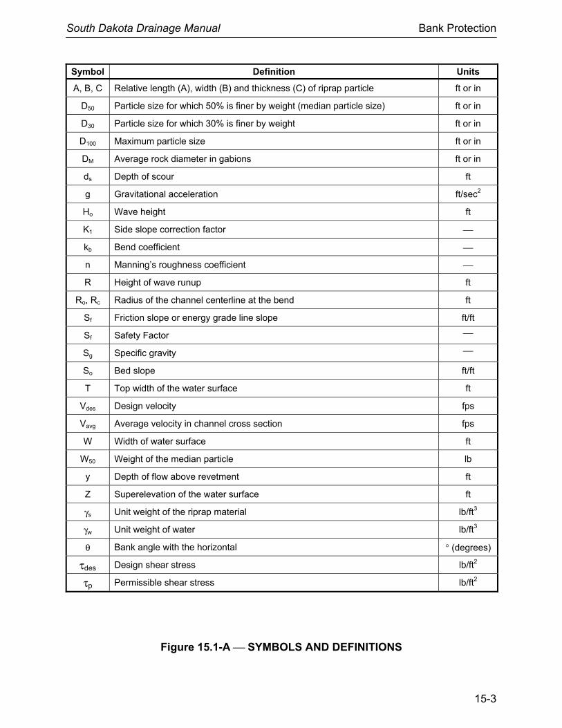
To provide consistency within this Chapter and throughout this Manual, use the symbols in Figure 15.1-A. These symbols were selected to be consistent with HEC 23 (Reference (1)). Coefficients are defined where they are used.
South Dakota Drainage Manual Bank Protection
15-3
Symbol Definition Units
A, B, C Relative length (A), width (B) and thickness (C) of riprap particle ft or in
D50 Particle size for which 50% is finer by weight (median particle size) ft or in
D30 Particle size for which 30% is finer by weight ft or in
D100 Maximum particle size ft or in
DM Average rock diameter in gabions ft or in
ds Depth of scour ft
g Gravitational acceleration ft/sec2
Ho Wave height ft
K1 Side slope correction factor ⎯
kb Bend coefficient ⎯
n Manning’s roughness coefficient ⎯
R Height of wave runup ft
Ro, Rc Radius of the channel centerline at the bend ft
Sf Friction slope or energy grade line slope ft/ft
Sf Safety Factor ⎯
Sg Specific gravity ⎯
So Bed slope ft/ft
T Top width of the water surface ft
Vdes Design velocity fps
Vavg Average velocity in channel cross section fps
W Width of water surface ft
W50 Weight of the median particle lb
y Depth of flow above revetment ft
Z Superelevation of the water surface ft
γs Unit weight of the riprap material lb/ft3
γw Unit weight of water lb/ft3
θ Bank angle with the horizontal ° (degrees)
τdes Design shear stress lb/ft2
τp Permissible shear stress lb/ft2
Figure 15.1-A ⎯ SYMBOLS AND DEFINITIONS

South Dakota Drainage Manual Bank Protection
15-4
15.2 SELECTION OF DESIGN FREQUENCY
To provide an acceptable standard level of service, SDDOT uses established design frequencies (see Figure 7.6-A) that are based on the classification of the highway facility, the allowable risk for that facility, and the appropriate drainage structure under design.

South Dakota Drainage Manual Bank Protection
15-5
15.3 BANK AND LINING FAILURE MODES
Prior to designing a bank stabilization scheme, the hydraulic designer should be aware of common erosion mechanisms, revetment failure modes and the causes of bank erosion processes. Inadequate recognition of potential erosion processes at a particular site may lead to failure of the revetment system.
Many causes of bank erosion and revetment failure have been identified. Some of the common causes include abrasion, debris flows, water flow, eddy action, flow acceleration, unsteady flow, freeze/thaw, human actions on the bank, ice, precipitation, waves, toe erosion and subsurface flows. A combination of causes usually produce bank and revetment failures and the primary mechanism or cause is difficult to determine. Failures may be classified by failure mode including:
• particle erosion, • translational slide, • modified slump, and • slump. For more detail, see HEC 11 (Reference (3)).

South Dakota Drainage Manual Bank Protection
15-6
15.4 REVETMENT TYPES
Figure 15.4-A provides the types of slope protection or revetment that SDDOT uses for bank and shore protection and stabilization in the order that they should be considered. The Figure also provides the section number where each of these revetment types is described and a reference to where design guidance is provided. HEC 23 (Reference (1)) is the source of all of the design guidance. Section 15.7 includes the design guidance from HEC 23 for rock riprap; see Section 15.8 for gabions.
Revetment Types Type Description
(Section) Design
(Section or DG*)
Rock and Rubble Riprap Flexible 15.4.1 15.7
Gabions Flexible 15.4.2 15.8
Wire-Enclosed Rock Flexible 15.4.3 DG 6
Articulated Block (Precast Concrete) Flexible 15.4.4 DG 8
Partially and Fully Grouted Rock Rigid 15.4.5 DG 12
Concrete Slope Protection Rigid 15.4.6 HEC 11
Biotechnical Engineering (Vegetative plantings)
Flexible 15.4.7 HEC 23
* HEC 23, Design Guideline (DG)
Figure 15.4-A ⎯ SELECTION OF REVETMENT TYPE 15.4.1 Rock and Rubble Riprap
Riprap is a layer or facing of rock, which is dumped or hand-placed to prevent erosion, scour or sloughing of a structure or embankment. Materials other than rock are also referred to as riprap; these include rubble, broken concrete slabs and preformed concrete shapes (e.g., slabs, blocks, rectangular prisms). These materials are similar to rock in that they can be hand placed or dumped onto an embankment to form a flexible revetment.
SDDOT uses riprap with considerable frequency; however, it is not readily available in many parts of the State. Gabions are often used where riprap is not practical. See Section 15.7 for design guidelines for riprap.

South Dakota Drainage Manual Bank Protection
15-7
15.4.2 Gabions
Gabion revetments consist of rectangular, wire-mesh baskets filled with rock. These revetments are formed by filling pre-assembled wire baskets with rock and anchoring them to the channel bottom or bank. The gabion baskets comprising the mattress generally have a depth dimension that is much smaller than their width or length. Block gabions, in contrast, are more equi-dimensional, having depths that are approximately the same as their widths and of the same order of magnitude as their lengths. They are typically rectangular or trapezoidal in shape. Block gabion revetments are formed by stacking the individual gabion blocks in a stepped fashion. Gabions are the most common type of bank protection used by SDDOT where riprap is not readily available. See Section 15.8 for gabion design guidelines.
15.4.3 Wire-Enclosed Rock
Wire-enclosed rock differs from gabions and gabion (Reno) mattresses because it is a continuous framework rather than individual, interconnected baskets. In addition, wire-enclosed rock is typically anchored to the embankment with steel stakes that are driven through the mattress. Rock-and-wire mattress is usually 1.0 ft or less in thickness; a gabion is thicker and nearly equi-dimensional. Construction of wire-enclosed rock is usually faster than gabions or gabion mattresses, and it also requires less wire mesh because internal junction panels are not used. Wire-enclosed rock is used primarily for slope protection. It has been used for bank protection, guide bank slope protection and in conjunction with gabions placed at the toe of slope. HEC 23 (Reference (1)), Design Guideline 6, should be used for the design of wire-enclosed rock.
15.4.4 Precast Concrete Block
Precast concrete blocks or articulated concrete block (ACB) systems provide a flexible alternative to riprap, gabions and rigid revetments. ACBs provide a more uniform surface for pedestrian or vehicular traffic. These systems consist of preformed units that either interlock or are held together by steel rods or cables, or that abut together to form a continuous blanket or mat. HEC 23 (Reference (1)), Design Guideline 8, considers two applications for ACBs:
• Application 1 ⎯ bankline and abutment revetment and bed armor • Application 2 ⎯ pier scour protection. There is little experience with the use of articulated block systems as a scour countermeasure for bridge piers alone. More frequently, these systems have been used for revetments and channel armoring where the mat is placed across the entire channel width and keyed into the abutments or bank protection. For this reason, guidelines for placing articulated block systems at banklines and channels are well

South Dakota Drainage Manual Bank Protection
15-8
documented, but there are few published guidelines on the installation of these systems around bridge piers. Where articulated block systems have been installed as a countermeasure for scour at bridge piers, cable-tied concrete mats have more often been used.
Specifications and design guidelines for selecting, installing and anchoring ACBs with filter material are documented in HEC 11 (Reference (3)). HEC 11 directs the designer to the manufacturer’s literature for the selection of appropriate block sizes for a given hydraulic condition. Hydraulic design criteria are unique to the type of manufactured ACB and the system site conditions. A procedure to develop hydraulic design criteria for ACBs given the appropriate performance data for a particular block system is presented in HEC 23 (Reference (1)).
15.4.5 Partially and Fully Grouted Rock
Grouted rock revetment consists of rock slope protection with voids filled with concrete grout to form a monolithic armor. Grouted rock is a rigid revetment; it will not conform to changes in the bank geometry due to settlement. As with other monolithic revetments, grouted rock is particularly susceptible to failure from undermining and the subsequent loss of the supporting bank material. Although it is rigid, grouted rock is not strong; therefore, the loss of even a small area of bank support can cause failure of large portions of the revetment. HEC 23 (Reference (1)), Chapter 5, provides a discussion of fully grouted rock.
An alternative to grouted rock is partially grouted rock. In general, the objective of partially grouted rock is to increase the stability of the riprap without sacrificing all of the flexibility. As with fully grouted rock, partially grouted rock may be well suited for areas where rock of sufficient size is not available to construct a loose riprap revetment. The grout for partially grouted rock is placed on the riprap, leaving significant voids in the riprap matrix and considerable open space on the surface. The holes in the grout allow for drainage of pore water so a filter is required. The grout forms conglomerates of rock so that its stability against particle erosion is greatly improved and, as with fully grouted riprap, a smaller thickness of stone can be used. Although not as flexible as riprap, partially grouted rock will conform somewhat to bank settlement and toe exposure. HEC 23 (Reference (1)), Design Guideline 12, should be consulted for guidance on partially grouted riprap.
15.4.6 Concrete Slope Protection
Concrete pavement revetments (concrete slope pavement) are cast-in-place on a prepared slope to provide the necessary bank protection. Like grouted rock, concrete pavement is a rigid revetment that does not conform to changes in bank geometry due to a removal of foundation support by subsidence, undermining, outward displacement by hydrostatic pressure, slide action or erosion of the supporting embankment at its

South Dakota Drainage Manual Bank Protection
15-9
ends. The loss of even small sections of the supporting embankment can cause complete failure of the revetment system. Concrete pavement revetments are also among the most expensive stream bank protection designs. HEC 11 (Reference (3)), Chapter 6, should be consulted for recommended concrete slope paving practices.
15.4.7 Vegetative Plantings (Biotechnical Engineering)
Vegetative plantings (biotechnical engineering) for bank stabilization have no design criteria. Research is being conducted in these techniques. If vegetation is being considered for the stabilization of a reach, the designer should consult HEC 23 (Reference (1)), Chapter 6, to help evaluate the advantages and disadvantages associated with alternative systems.

South Dakota Drainage Manual Bank Protection
15-10
15.5 DESIGN CONCEPTS
This Section discusses design concepts related to the design of bank protection, including uniform flow assumption, section geometry and flow resistance.
15.5.1 Uniform Flow Assumption
Design relationships presented in this Chapter are based on the assumption of uniform, steady, subcritical flow. These relationships are also valid for gradually varying flow conditions. Although the individual hydraulic relationships presented are not in themselves applicable to rapidly varying, unsteady or supercritical flow conditions, procedures are presented for extending their use to these flow conditions. See Chapter 9 “Roadside Channels” for more details related to channel design.
Non-uniform, unsteady and near supercritical flow conditions create stresses on the channel boundary that are significantly different from those induced by uniform, steady, subcritical flow. These stresses are difficult to assess quantitatively. The stability factor method of riprap design presented in Section 15.7.1 provides a means of adjusting the final riprap design (that is based on relationships derived for steady, uniform, subcritical flow) for the uncertainties associated with other flow conditions. The adjustment is made through the assignment of a stability factor. The magnitude of the stability factor is based on the level of uncertainty inherent in the design flow conditions.
15.5.2 Section Geometry
Design procedures presented in this Chapter require knowledge of the channel cross section geometry. The cross section geometry is necessary to establish the hydraulic design parameters (e.g., flow depth, top width, velocity, hydraulic radius) required by the riprap design procedures and to establish a construction cross section for placement of the revetment material. The intent is to develop a section that reasonably simulates a worst-case condition with respect to revetment stability.
15.5.3 Flow Resistance
The hydraulic analysis performed as a part of the revetment design process requires the estimation of Manning’s roughness coefficient. Physical characteristics upon which the resistance equations are based include the channel base material, surface irregularities, variations in section geometry, bed form, obstructions, vegetation, channel meandering, flow depth and channel slope. In addition, seasonal changes in these factors should also be considered. See USGS Water Supply Paper 1849 (Reference (4)) for pictures and advice on the selection of Manning’s n values for natural channels.

South Dakota Drainage Manual Bank Protection
15-11
15.6 DESIGN GUIDELINES FOR PROTECTION LIMITS
15.6.1 Extent of Protection
The extent of protection refers to the longitudinal and vertical extent of protection required to adequately protect the channel bank.
15.6.1.1 Longitudinal Extent
SDDOT practice in straight reaches is to extend riprap a minimum of 12 ft downstream of the feature to be protected if the velocity is ≤ 11 fps. Figure 15.6-A illustrates SDDOT practice for bends. The minimum distances recommended for bank protection are an upstream distance of one channel width and a downstream distance of 1½ channel widths from corresponding reference lines. All reference lines pass through tangents to the bend at the bend entrance or exit. This criterion is based on an analysis of flow conditions in symmetric channel bends under ideal laboratory conditions. Real-world conditions are rarely as simplistic. Field observations are a valuable tool in determining the extent of longitudinal limits.
Figure 15.6-A ⎯ LONGITUDINAL EXTENT OF REVETMENT PROTECTION

South Dakota Drainage Manual Bank Protection
15-12
In curved channel reaches, the scars on the channel bank can be used to establish the upstream limit of erosion. A minimum of one channel width should be added to the observed upstream extent of erosion to define the limit of protection. The downstream limit of protection required in curved channel reaches is not as easy to define. Because the natural progression of bank erosion is in the downstream direction, the present visual limit of erosion might not define the ultimate downstream limit. Additional analysis based on consideration of flow patterns in the channel bend may be required.
15.6.1.2 Vertical Extent
The vertical extent of protection required from a revetment includes design height and foundation or toe depth.
15.6.1.2.1 Design Height
The design height of a revetment should be equal to the design high-water elevation plus at least 1 ft for freeboard. Freeboard is provided to ensure that the desired degree of protection will not be compromised by the following factors:
• wave action (from wind or boat traffic); • superelevation in channel bends; • hydraulic jumps; and • flow irregularities due to piers, transitions and flow junctions. In addition, erratic phenomena (e.g., unforeseen embankment settlement, the accumulation of silt, trash and debris in the channel, aquatic or other growth in the channels, ice flows) should be considered when establishing freeboard heights. Also, wave runup on the bank should be considered.
The estimation of wave heights from wind- and boat-generated waves is not as straightforward as other wave sources. Figure 15.6-B provides a definition sketch for the wave height discussion to follow. The height of boat-generated waves should be estimated from observations. Wave runup is a function of the wave height, wave period, bank angle and bank surface characteristics (as represented by different revetment materials). For wave heights less than 2 ft, wave runup can be computed using Figure 15.6-C and Figure 15.6-D. The wave runup height (R) given in Figure 15.6-C is for concrete pavement. Correction factors are provided in Figure 15.6-D for reducing the runup magnitude for other revetment materials. The correction factor is multiplied by the wave height to get the resulting wave runup height. Additional guidance for designing riprap attacked by waves is found in HEC 23 (Reference (1)), Design Guideline 17. The website for South Dakota State University provides wind speed and direction for South Dakota cities.

South Dakota Drainage Manual Bank Protection
15-13
Key: R = wave runup, ft ds = depth of scour, ft Ho = wave height, ft SWL = surface water level θ = bank angle with the horizontal, degrees
Figure 15.6-B ⎯ WAVE HEIGHT DEFINITION SKETCH
Note: HEC 23 (Design Guideline 17) indicates that the upper limit can be calculated from R = 3.2(rHo).
Figure 15.6-C ⎯ WAVE RUNUP ON SMOOTH, IMPERMEABLE SLOPES (Reference (3))

South Dakota Drainage Manual Bank Protection
15-14
Slope Surface (Material Type) Placement Method Correction Factor
Concrete pavement — 1.00
Concrete blocks (voids < 20%) fitted 0.90
Concrete blocks (20% < voids < 40%) fitted 0.70
Concrete blocks (40% < voids < 60%) fitted 0.50
Grass ⎯ 0.85 – 0.90
Rock riprap (angular) random 0.50 – 0.60
Rock riprap (round) random 0.60 – 0.65
Rock riprap hand-placed 0.85 – 0.90
Grouted rock ⎯ 0.90
Wire-enclosed rocks/gabions ⎯ 0.80
Figure 15.6-D ⎯ CORRECTION FACTORS FOR WAVE RUNUP (Reference (3)) As indicated, there are many factors that should be considered in the selection of an appropriate freeboard height. At a minimum, it is recommended that a freeboard height of 1 ft to 2 ft be used in unconstricted reaches and 2 ft to 3 ft in constricted reaches. FEMA requires 3 ft for levee protection and 4 ft at bridges (over levees) for the 100-yr flood. See the FEMA Fact Sheet “Requirements for Mapping Levees Complying with Section 65.10 of the NFIP Regulations.”
When computational procedures indicate that additional freeboard may be required, the greater height should be used. In addition, it is recommended that the designer observe wave and flow conditions during various seasons of the year (if possible), consult existing records and interview individuals who have knowledge of past conditions when establishing the necessary vertical extent of protection for a particular revetment installation.
15.6.1.2.2 Toe Depth
Undermining the revetment toe is one of the primary mechanisms of revetment failure. In the design of bank protection, estimates of the depth of scour are needed so that the protective layer is placed sufficiently low in the streambed to prevent undermining. The ultimate depth of scour should consider channel degradation and natural scour and fill processes.
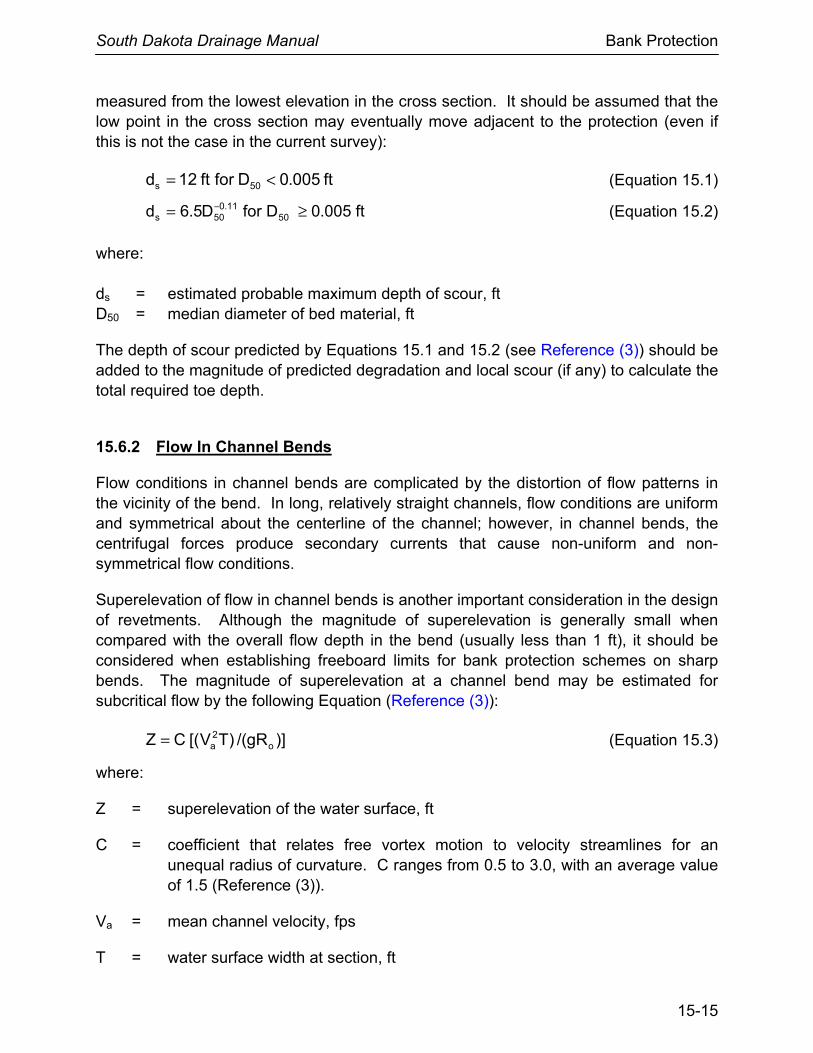
In the absence of a more detailed hydraulic analysis, the relationships presented in Equations 15.1 and 15.2 (Reference (3)) can be used to estimate the probable maximum depth of scour due to natural scour and fill phenomenon in straight channels and in channels having mild bends. In application, the depth of scour, ds, should be
South Dakota Drainage Manual Bank Protection
15-15
measured from the lowest elevation in the cross section. It should be assumed that the low point in the cross section may eventually move adjacent to the protection (even if this is not the case in the current survey):
ft005.0Dforft12d 50s <= (Equation 15.1)
ft005.0DforD5.6d 5011.0
50s ≥= − (Equation 15.2)
where: ds = estimated probable maximum depth of scour, ft D50 = median diameter of bed material, ft
The depth of scour predicted by Equations 15.1 and 15.2 (see Reference (3)) should be added to the magnitude of predicted degradation and local scour (if any) to calculate the total required toe depth.
15.6.2 Flow In Channel Bends
Flow conditions in channel bends are complicated by the distortion of flow patterns in the vicinity of the bend. In long, relatively straight channels, flow conditions are uniform and symmetrical about the centerline of the channel; however, in channel bends, the centrifugal forces produce secondary currents that cause non-uniform and non-symmetrical flow conditions.
Superelevation of flow in channel bends is another important consideration in the design of revetments. Although the magnitude of superelevation is generally small when compared with the overall flow depth in the bend (usually less than 1 ft), it should be considered when establishing freeboard limits for bank protection schemes on sharp bends. The magnitude of superelevation at a channel bend may be estimated for subcritical flow by the following Equation (Reference (3)):
)]gR/()TV[(CZ o2a= (Equation 15.3)
where:
Z = superelevation of the water surface, ft
C = coefficient that relates free vortex motion to velocity streamlines for an unequal radius of curvature. C ranges from 0.5 to 3.0, with an average value of 1.5 (Reference (3)).
Va = mean channel velocity, fps
T = water surface width at section, ft

South Dakota Drainage Manual Bank Protection
15-16
g = gravitational acceleration, 32.2 ft/sec2
Ro = the mean radius of the channel centerline at the bend, ft

South Dakota Drainage Manual Bank Protection
15-17
15.7 DESIGN GUIDELINES FOR ROCK RIPRAP
This Section presents design guidelines for the design of rock riprap. The design guidance is from HEC 23 (Reference (1)), Design Guideline 4, which is based on USACE EM-1601 (Reference (5)). The procedure uses both velocity and depth as its primary design parameters.
Riprap material, geotextile and impermeable plastic membrane requirements are found in the SDDOT Standard Specifications for Roads and Bridges.
15.7.1 Riprap Size
The EM-1601 Equation can be used with uniform or gradually varying flow. Coefficients are included to account for the desired safety factor for design, specific gravity of the riprap stone, bank slope and bendway character. The EM-1601 Equation is:
( ) ( )5.2
g1
desTVSf30
gy)1S(K
VCCCSyD
−= (Equation 15.4)
where: D30 = particle size for which 30% is finer by weight, ft
y = local depth of flow above particle, ft
Sf = safety factor (should be > 1.0)
Cs = stability coefficient (for blanket thickness = D100 or 1.5D50, whichever is greater, and uniformity ratio D85/D15 = 1.7 to 5.2)
= 0.30 for angular rock
= 0.375 for rounded rock
Cv = velocity distribution coefficient
= 1.0 for straight channels or the inside of bends
= 1.283 – 0.2 log(Rc/W) for the outside of bends (1.0 for Rc/W > 26)
= 1.25 downstream from concrete channels
= 1.25 at the end of dikes
CT = blanket thickness coefficient given as a function of the uniformity ratio D85/D15. CT = 1.0 is recommended because it is based on very limited data.

South Dakota Drainage Manual Bank Protection
15-18
Vdes = characteristic velocity for design, defined as the depth-averaged velocity at a point 20% upslope from the toe of the revetment, fps:
For natural channels: Vdes = Vavg(1.74 – 0.52log(Rc/W)) Vdes = 0.90Vavg for Rc/W > 42 For trapezoidal channels: Vdes = Vavg (1.71 – 0.78 log (Rc/W)) Vdes = 0.82Vavg for Rc/W > 14
Vavg = channel cross-sectional average velocity, fps K1 = side slope correction factor
= 6.1
)32sin()14sin(
1
°°−θ−
where θ is the bank angle in degrees Rc = centerline radius of curvature of channel bend, ft
W = width of water surface at upstream end of channel bend, ft
Sg = specific gravity of riprap (usually taken as 2.48 by SDDOT)
g = acceleration due to gravity, 32.2 ft/sec2 The values of the coefficients used in the EM-1601 Equation are provided in the variable definitions as given above. They can also be determined graphically from charts provided in Appendix B of EM-1601. Using the recommended riprap gradations from HEC 23 (Reference (1)), the D30 size of the riprap determined by Equation 15.4 is related to the recommended median (D50) size by:
D50 = 1.20D30 (Equation 15.5)
The flow depth (y) used in Equation 15.4 is defined as the local flow depth above the particle. The flow depth at the toe of slope is typically used for bank revetment applications; alternately, the average channel depth can be used. The smaller of these values will result in a slightly larger computed D30 size, because riprap size is inversely proportional to y0.25.
The blanket thickness coefficient (CT) is 1.0 for standard riprap applications where the thickness is equal to 1.5D50 or to D100, whichever is greater. Because only limited data is available for selecting lower values of CT when greater thicknesses of riprap are used, a value of 1.0 is reasonable for all applications.

South Dakota Drainage Manual Bank Protection
15-19
The recommended safety factor (Sf) is 1.2 for bank revetment. Greater values should be considered where there is significant potential for ice or impact from large debris, freeze-thaw degradation that would significantly decrease particle size, or large uncertainty in the design variables, especially velocity.
A limitation to Equation 15.4 is that the longitudinal slope of the channel should not be steeper than 2.0% (0.02 ft/ft). For steeper channels, the riprap sizing approach for overtopping flows should be considered and the results compared with Equation 15.4 (see HEC 23 (Reference (1)), Design Guideline 5).
Once a design size is established, a standard size class can be selected, if design criteria and economic considerations permit. Using standard sizes, the appropriate gradation can be achieved by selecting the next larger size class, thereby creating a slightly over-designed structure. Recommended size classes and gradation characteristics are derived from HEC 23 (Reference (1)) and are provided in the SDDOT Standard Specifications for Roads and Bridges.
15.7.2 Bank Angle
Normal bank slope for riprap should be no steeper than 2H:1V. Steeper slopes may be constructed but may require special design.
15.7.3 Thickness of Riprap
All stones should be contained within the riprap layer thickness, with little or no oversized stones protruding above the surface of the riprap matrix. The following criteria are recommended in HEC 23 (Reference (1)) for revetment riprap:
1. Layer thickness should not be less than the spherical diameter of the D100 stone or less than 1.5 times the spherical diameter of the D50 stone, whichever results in the greater thickness.
2. Layer thickness should not be less than 1 ft for practical placement.
3. Layer thickness determined either by criterion 1 or 2 above should be increased by 50% when the riprap is placed underwater to compensate for uncertainties associated with this placement condition.
15.7.4 Riprap Shape and Gradation
Riprap design methods typically yield a required size of stone that will result in stable performance under the design loadings. Because stone is produced and delivered in a range of sizes and shapes, the required size of stone is often stated in terms of a minimum allowable representative size. For example, the designer may specify a

South Dakota Drainage Manual Bank Protection
15-20
minimum D50 or D30 for the rock comprising the riprap, thus indicating the size for which 50% or 30% (by weight) of the particles are smaller. Stone sizes can also be specified in terms of weight (e.g., W50 or W30), using an accepted relationship between size and volume and the known (or assumed) density of the particle. Normal practice is to use standard SDDOT gradation.
15.7.4.1 Shape
The shape of a stone can be generally described by designating three axes of measurement ⎯ major, intermediate and minor, also known as the “A, B and C” axes, as shown below.
Riprap stones or rubble should not be thin and platy, nor should they be long and needle-like. Therefore, specifying a maximum allowable value for the ratio A/C, also known as the shape factor, provides a suitable measure of particle shape, because the B axis is intermediate between the two extremes of Length A and Thickness C. A maximum allowable value of 3.0 is recommended:
A/C ≤ 3.0 (Equation 15.6)
For riprap applications, stones that are non-polished and angular are preferred, due to the higher degree of interlocking, creating greater stability compared to rounded particles of the same weight.
15.7.4.2 Density
A measure of density of natural rock is the specific gravity Sg, which is the ratio of the density of a single (solid) rock particle γs to the density of water γw:
Sg = γs/γw (Equation 15.7)
SDDOT uses a specific gravity of 2.48 by specification for riprap applications. Where quarry sources uniformly produce rock with a specific gravity significantly greater than

South Dakota Drainage Manual Bank Protection
15-21
2.48 (e.g., dolomite, where Sg = 2.7 to 2.8), the equivalent stone size can be substantially reduced and still achieve the same particle weight gradation.
15.7.4.3 Size and Weight
Based on field studies, the recommended relationship between size and weight is given by:
W = 0.85(γsd3) (Equation 15.8)
where:
W = weight of stone, lb γs = density of stone, lb/ft3 d = size of intermediate (“B”) axis, ft 15.7.5 Filter Requirements
The importance of the filter component of revetment riprap installation should not be underestimated. Geotextile filters and granular filters may be used in conjunction with riprap bank protection. When using a granular stone filter, the layer should have a minimum thickness of 4 times the D50 of the filter stone or 6 in, whichever is greater. When placing a granular filter under water, its thickness should be increased by 50%.
The filter should retain the coarser particles of the subgrade while remaining permeable enough to allow infiltration and exfiltration to occur freely. It is not necessary to retain all particle sizes in the subgrade; in fact, it is beneficial to allow the smaller particles to pass through the filter, leaving a coarser substrate behind. Detailed aspects of filter design are presented in HEC 23 (Reference (1)), Design Guideline 16, HEC 11 (Reference (3)) and FHWA, Geosynthetic Design and Construction Guidelines (Reference (6)).
15.7.6 Design Example
Given:
Riprap will be designed for a 100-ft wide natural channel on a bend that has a centerline radius (Rc) of 500 ft. The radius of curvature divided by the width (Rc/W) is 5.0. The revetment will have a 2H:1V sideslope (26.6 degrees), and the angular riprap will have a specific gravity of 2.54. A safety factor (Sf) of 1.2 is desired. Toe scour on the outside of the bend has been determined to be 2.5 ft during the design event. CT = 1.0.
The following data were obtained from hydraulic modeling of the design event:

South Dakota Drainage Manual Bank Protection
15-22
• Average Channel Velocity = 7.2 fps • Flow Depth at Bank Toe = 11.4 ft Solution: Step 1 Compute the side slope correction factor (or select from graph on Plate B-39
of EM-1601):
87.0)32sin(
)146.26sin(1
)32sin()14sin(
1K6.16.1
1 =
°°−°−=
°°−θ−=
Step 2 Select the appropriate stability coefficient for angular rounded riprap: Cs = 0.30
Step 3 Compute the vertical velocity factor (Cv) for Rc/W = 5.0:
Cv = 1.283 – 0.2log(Rc/W) = 1.283 – 0.2log(5.0) = 1.14 Step 4 Compute local velocity on the side slope (Vdes) for a natural channel with
Rc/W = 5.0:
Vdes = Vavg [1.74 – 0.52log(Rc/W)] = 7.2[1.74 – 0.52log(5.0)] = 9.9 fps Step 5 Compute the D30 size using Equation 15.4:
( ) ( )5.2
g1
desTVSf30
gy)1S(K
VCCCSyD
−=
=
5.2
)4.11)(2.32)(154.2)(87.0(
9.9)0.1)(14.1)(30.0)(2.1(4.11
−
= 0.62 ft Step 6 Compute the D50 size for a target gradation of D85/D15 = 2.0: D50 = 1.2D30 = 1.2(0.62) = 0.74 ft = 8.9 in Step 7 Select the class of riprap that provides D50 = 9 in (use Class A riprap).
Step 8 Determine the depth of riprap embedment below the streambed at the toe of the bank slope. Because toe scour is expected to be 2.5 ft, the 2H:1V slope should be extended below the natural bed level 5 ft horizontally out from the toe to accommodate this scour. Alternately, a mounded riprap toe 2.5-ft high could be established at the base of the slope and allowed to self-launch when toe scour occurs.

South Dakota Drainage Manual Bank Protection
15-23
15.8 DESIGN GUIDELINES FOR GABIONS
The following guidelines are from HEC 23 (Reference (1)), Design Guideline 10. Gabions were designed prior to 2010 using USACE EMRRP-SR-22 (Reference (7)). HEC 11 (Reference (3)) should also be consulted for construction details.
SDDOT Standard Plate for “Bank and Channel Protection Gabions” contains standard gabion sizes. Gabion material, geotextile and impermeable plastic membrane requirements are found in the SDDOT Standard Specifications for Roads and Bridges. A software package known as CHANLPRO has been developed by Maynord (Reference (8)), which can be used to design gabions.
15.8.1 Overview
Gabions come in two basic forms ⎯ the gabion basket and the gabion mattress. Both types consist of wire mesh baskets filled with cobble or small boulder material. The baskets are used to maintain stability and to protect streambanks and beds. The difference between a gabion basket and a gabion mattress is the thickness and the aerial extent of the basket. The benefit of gabions is that they can be filled with rocks that would individually be too small to withstand the erosive forces of the stream.
The gabion mattress is shallower (0.5 ft to 1.5 ft) than the gabion basket and is designed to protect the bed or banks of a stream against erosion. Gabion baskets are normally much thicker (approximately 1.5 ft to 3 ft) and cover a much smaller area. They are used to protect banks where mattresses are not adequate or are used to stabilize slopes, construct drop structures, pipe outlet structures or nearly any other application where soil should be protected from the erosive forces of water.
The rocks contained within the gabions provide substrates for a wide variety of aquatic organisms. Organisms that have adapted to living on and within the rocks have an excellent home, but vegetation may be difficult to establish unless the voids in the rocks contained within the baskets are filled with soil.
If large woody vegetation is allowed to grow in the gabions, there is a risk that the baskets will break when the large woody vegetation is uprooted or as the root and trunk systems grow. Thus, it is normally not acceptable to allow large woody vegetation to grow in the baskets. The possibility of damage should be weighed against the desirability of vegetation on the area protected by gabions and the stability of the large woody vegetation.
If large woody vegetation is kept out of the baskets, grasses and other desirable vegetation types may be established and provide a more aesthetic and ecologically desirable project than gabions alone.

South Dakota Drainage Manual Bank Protection
15-24
15.8.2 Hydraulic Stability Design Procedure
Gabion mattress design methods typically yield a required D50 stone size that will result in stable performance under the design hydraulic loading. The required size of stone is often stated in terms of a minimum and maximum allowable size because stone is produced and delivered in a range of sizes and shapes. For example, ASTM Standard D 6711, “Standard Practice for Specifying Rock to Fill Gabions, Revet Mattresses, and Gabion Mattresses,” recommends the following:
Mattress Thickness Range of Stone Sizes
6 in 3 in to 5 in 9 in 3 in to 5 in
12 in 4 in to 8 in 18 in 4 in to 8 in
ASTM Standard D 6711 also indicates that the fill should be well graded with a full range of sizes between the upper and lower limits. The rocks used to fill gabion mattresses should be hard, dense and durable. In general, rocks used for filling gabion mattresses should be of the same material quality as would be used for riprap.
15.8.3 Selecting a Target Safety Factor
The designer must determine what safety factor should be used for a particular application. Typically, a minimum allowable safety factor of 1.2 is used for revetment (bank protection) when the project hydraulic conditions are well known and the installation can be conducted under well-controlled conditions. Higher safety factors are used for protection at bridge piers, abutments and at channel bends, due to the complexity in computing hydraulic conditions at these locations.
As an example, the Harris County Flood Control District (HCFCD), Texas (Reference (9)) has developed a simple flowchart approach that considers the type of application, uncertainty in the hydraulic and hydrologic models used to calculate design conditions, and consequences of failure to select an appropriate target safety factor to use when designing various types of Articulating Concrete Block (ACB) installations. In this approach, the minimum allowable safety factor for ACBs at bridge piers, for example, is 1.5. This base value is then multiplied by two factors, each equal to or greater than 1.0, to account for risk and uncertainty. Figure 15.8-A shows the HCFCD flowchart method. The method is also considered appropriate for gabion mattresses, because the design method results in a calculated safety factor.

South Dakota Drainage Manual Bank Protection
15-25
Type of Modeling Used XMDeterministic(e.g., HEC-RAS, RMA 2V) 1.0 – 1.3
Empirical or Stochastic(e.g., Manning orRational Equation) 1.4 – 1.7
Estimates 1.8 – 2.0
Consequence of Failure XcLow 1.0 – 1.2Medium 1.3 – 1.5Highway 1.6 – 1.8Extreme or loss of life 1.9 – 2.0
Example Applications SFBChannel bed or bank 1.2 – 1.4Bridge pier or abutment 1.5 – 1.7Overtopping spillway 1.8 – 2.0
Step 1: Determine SFB based on application; SFB= (1.2 to 2.0)
Step 2: Determine Xcbased on consequence of failure; Xc = (1.0 to 2.0)
Step 3: Determine XMbased on uncertainty in hydrologic/hydraulic modeling; XM = (1.0 to 2.0)
Step 4: Calculate target safety factor (SFT) using equation presented below:
SFT = SFB XCXM
Where: SFT = target factor of safetySFB = base factor of safetyXC = multiplier based on
consequence of failureXM = multiplier based on
model uncertainty
Guidance
Guidance
Guidance
Notes:
The intent of this flowchart is to provide a systematic procedure for pre-selecting a target safety factor (SFT) for an ACB system. No simple decision-support system can encompass all significant factors that will be encountered in practice; therefore, this flowchart should not replace prudent engineering judgment.
SFB is a base safety factor that considers the overall complexity of flow that the ACB system will be exposed to. SFBshould reflect erosive flow characteristics that can not be practically modeled (e.g., complex flow lines and turbulence). XC is a multiplier to incorporate conservatism when the consequence of failure is severe when compared to the cost of the ACB system. XM is a multiplier to incorporate conservatism when the degree of uncertainty in the modeling approach is high (e.g., the use of a simple model applied to a complex system).
Figure 15.8-A — SELECTING A TARGET SAFETY FACTOR (Reference (9))

South Dakota Drainage Manual Bank Protection
15-26
15.8.4 Design Procedure
For gabion mattresses placed on channel beds or banks, the shear stress on the mattress is calculated as follows:
τdes = kb(γw)(y)(Sf) (Equation 15.9)
where:
τdes = design shear stress, lb/ft2 kb = bend coefficient (dimensionless) γw = unit weight of water, 62.4 lb/ft3
y = maximum depth of flow on revetment, ft S1 = slope of energy gradeline, ft/ft The bend coefficient kb is used to calculate the increased shear stress on the outside of a bend. This coefficient ranges from 1.05 to 2.0, depending on the severity of the bend. The bend coefficient is a function of the radius of curvature Re divided by the top width of the channel T, as follows:
kb = 2.0 for 2 ≥ Rc/T
2
ccb T
R0073.0
T
R06.238.2k
+
−= for 10 > Rc/T > 2 (Equation 15.10)
kb = 1.05 for Rc/T ≥ 10
The recommended procedure for determining the permissible shear stress for a gabion mattress is determined using the relationship provided in HEC 15 third edition (Reference (10)):
( ) 50wssp DC γ−γ=τ (Equation 15.11)
where:
τp = permissible shear stress, lb/ft2 D50 = median diameter of rockfill in mattress, ft Cs = stability coefficient for rock-filled gabion mattress equal to 0.10 γw = unit weight of water, 62.4 lb/ft3 γs = unit weight of stone, lb/ft3 The coefficient (Cs) is an empirical coefficient developed by Maynord (Reference (11)) from test data presented in Simons et al. (Reference (13)). Use of Cs = 0.10 is limited to the conditions of the testing program, which used angular rock and a ratio of maximum to minimum stone size from 1.5 to 2.0.

South Dakota Drainage Manual Bank Protection
15-27
The safety factor can be calculated as the ratio of the permissible shear stress divided by the applied shear stress:
des
pfS
ττ
= (Equation 15.12)
Minimum rock size should be at least 1.25 times larger than the aperture size of the wire mesh that comprises the mattress (Reference (12)). Rock should be well-graded between the minimum and maximum sizes to minimize the size of the voids in the matrix. If design criteria and economic criteria permit, standard gradations may be selected.
The thickness of the gabion mattress should be at least twice the average diameter of the rock fill, T ≥ 2D50. If the computed thickness does not match that of a standard gabion thickness, the next larger thickness of mattress should be used (Reference (11)). At a minimum, the thickness should be 6 in (Reference (12)).
15.8.5 Layout Details for Gabion Mattress Bank Revetment and Bed Armor
The following applies to the layout of a gabion mattress:
1. Longitudinal Extent. The revetment armor should be continuous for a distance that extends both upstream and downstream of the region that experiences hydraulic forces severe enough to cause dislodging and/or transport of bed or bank material. The minimum recommended distances are an upstream distance of 1.0 channel width and a downstream distance of 1.5 channel widths. The channel reach that experiences severe hydraulic forces is usually identified by site inspection, examination of aerial photography, hydraulic modeling or a combination of these methods.
Many site-specific factors have an influence on the actual length of channel that should be protected. Factors that control local channel width (e.g., bridge abutments) may produce local areas of relatively high velocity and shear stress due to channel constriction, but may also create areas of ineffective flow further upstream and downstream in “shadow zone” areas of slack water. In straight reaches, field reconnaissance may reveal erosion scars on the channel banks that will assist in determining the protection length required.
In meandering reaches, because the natural progression of bank erosion is in the downstream direction, the present limit of erosion may not necessarily define the ultimate downstream limit. HEC 20 (Reference (2)) provides guidance for the assessment of lateral migration. The hydraulic designer is encouraged to review this reference for proper implementation.
South Dakota Drainage Manual Bank Protection
15-28
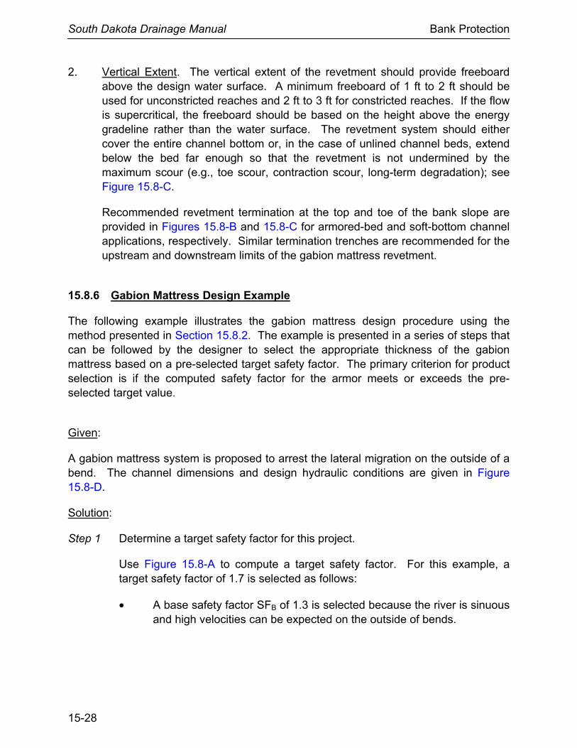
2. Vertical Extent. The vertical extent of the revetment should provide freeboard above the design water surface. A minimum freeboard of 1 ft to 2 ft should be used for unconstricted reaches and 2 ft to 3 ft for constricted reaches. If the flow is supercritical, the freeboard should be based on the height above the energy gradeline rather than the water surface. The revetment system should either cover the entire channel bottom or, in the case of unlined channel beds, extend below the bed far enough so that the revetment is not undermined by the maximum scour (e.g., toe scour, contraction scour, long-term degradation); see Figure 15.8-C.
Recommended revetment termination at the top and toe of the bank slope are provided in Figures 15.8-B and 15.8-C for armored-bed and soft-bottom channel applications, respectively. Similar termination trenches are recommended for the upstream and downstream limits of the gabion mattress revetment.
15.8.6 Gabion Mattress Design Example
The following example illustrates the gabion mattress design procedure using the method presented in Section 15.8.2. The example is presented in a series of steps that can be followed by the designer to select the appropriate thickness of the gabion mattress based on a pre-selected target safety factor. The primary criterion for product selection is if the computed safety factor for the armor meets or exceeds the pre-selected target value.
Given:
A gabion mattress system is proposed to arrest the lateral migration on the outside of a bend. The channel dimensions and design hydraulic conditions are given in Figure 15.8-D.
Solution:
Step 1 Determine a target safety factor for this project.
Use Figure 15.8-A to compute a target safety factor. For this example, a target safety factor of 1.7 is selected as follows:
• A base safety factor SFB of 1.3 is selected because the river is sinuous and high velocities can be expected on the outside of bends.

South Dakota Drainage Manual Bank Protection
15-29
Figure 15.8-B — RECOMMENDED LAYOUT DETAIL FOR BANK AND BED ARMOR
Figure 15.8-C — RECOMMENDED LAYOUT DETAIL FOR BANK REVETMENT WHERE NO BED ARMOR IS REQUIRED
Channel Conditions for Gabion Mattress Bank Revetment
Q = Channel discharge, cfs 4500
Vavg = Cross section average velocity, fps 8.7
y = Maximum depth, ft 5.0
Side slope, H:V 3H:1V
So = Bed slope, ft/ft 0.005
S1 = Slope of energy grade line, ft/ft 0.005
T = Channel top width, ft 120
Rc = Radius of curvature, ft 750
Figure 15.8-D — CHANNEL CONDITIONS FOR GABION MATTRESS BANK REVETMENT

South Dakota Drainage Manual Bank Protection
15-30
• The base safety factor is multiplied by a factor for the consequence of failure, Xc, using a value of 1.3, because at this location the consequence of failure is ranked as “low” to “medium.”
• The uncertainty associated with the hydrologic and hydraulic analysis is considered “low” for this site, based on available hydrologic and hydraulic data. Therefore, the factor, XM, for hydrologic and hydraulic uncertainty is given a value of 1.0.
The target safety factor for this project site is calculated as:
SFT = (SFB)(XC)(XM) = 1.7
Step 2 Calculate design shear stress.
The maximum bed shear stress at the cross section is calculated using Equation 15.9:
τdes = kb(γw)(y)(Sf)
First, calculate kb using Equation 15.10. Because Rc/T = 750/120 = 6.25:
kb = 2.38 – 0.206(6.25) + 0.0073(6.25)2 = 1.38
so: τdes = 1.38 (62.4 lb/ft2)(5.0 ft)(0.005 ft/ft) = 2.13 lb/ft2
Step 3 Calculate permissible shear stress.
From Equation 15.11:
τp = Cs (γs – γw )D50
Assuming a specific gravity of 2.65 for the stone fill, the unit weight of the individual stones is 2.65 × 62.4 = 165 lb/ft3. Using the recommended value of 0.10 for Cs, the permissible shear stress is plotted as a function of the D50 size of the stone fill in Figure 15.8-E. Using a D50 stone size of 4.5 in, a permissible shear stress is calculated using Equation 15.11:
( ) 233p ft/lb85.3
ft/in12in5.4
ft/lb4.62ft/lb16510.0 =−=τ

South Dakota Drainage Manual Bank Protection
15-31
Figure 15.8-E — PERMISSIBLE SHEAR STRESS AS A FUNCTION OF THE MEDIAN SIZE OF THE STONE FILL
Step 4 Calculate safety factor.
Using Equation 15.12, the safety factor is calculated as:
8.115.2
85.3S
des
pf ==
ττ
=
Because the calculated safety factor is larger than the site-specific target safety factor of 1.7 for this project, the stone sizing is appropriate.
Step 5 Specify the gabion mattress.
The thickness of the gabion mattress should be at least 2 times the D50 size of the stone fill. For this project, select a mattress with a thickness of at least 2 × 4.5 in = 9 in. A filter should be provided beneath the gabion mattress designed in accordance with the procedures described in HEC 23 (Reference (1)), Design Guideline 16.

South Dakota Drainage Manual Bank Protection
15-32
15.9 CHANNEL STABILIZATION METHODS
Case histories of hydraulic problems at 224 bridge sites (Reference (14)) provides information on the success (or failure) of the various countermeasures used to stabilize streams. Figure 15.9-A from Reference (14) illustrates how the general types of river training structures are used.
Note: Spurs, retards, dikes and jack fields may be either upstream or downstream from the
bridge.
Figure 15.9-A — PLACEMENT OF FLOW CONTROL STRUCTURES (Relative to Channel Banks, Crossing and Floodplain)
(Reference (14)) HEC 23 (Reference (1)) provides documentation on countermeasures that have been used in highway applications. Figure 15.9-B lists the channel stabilization methods from HEC 23 that SDDOT has used. Figure 15.9-C provides the HEC 23 assessment of the suitability of these methods for various river environments. The following Sections briefly describe these stabilization methods.

South Dakota Drainage Manual Bank Protection
15-33
River Training Structure Stream Instability Description
(Section) Design
(HEC 23) Vertical Lateral
Transverse Structures
Spur Dikes 15.8.1 DG 2
Bendway Weirs 15.8.2 DG 1
Grade Control 15.8.3 DG 3
Longitudinal Structures
Guide Banks 15.8.4 DG 15
Retardance Structures 15.8.5 CH 3
Bulkheads 15.8.6 CH 3
well suited/primary use possible application/secondary use unsuitable/rarely used DG is the Design Guideline in HEC 23 (Reference (1)), Volume 2. CH is the chapter in HEC 23 (Reference (1)), Volume 1.
Figure 15.9-B — CHANNEL STABILIZATION METHODS River Training Structure
Suitable River Environment
River Type Stream
Size Bend
Radius Bed
MaterialDebris/
Ice Load Bank
Condition Floodplain
B = braided M = meandering S = straight
W = wide M = moderate S = small
L = long M = moderate S = short
C = coarse S = sand F = fine
H = high M = moderateL = low
V = vertical S = steep F = flat
W = wide M = moderate N = narrow
Transverse Structures
Spur Dikes B, M W, M L, M Bendway Weirs
B, M M, S
Grade Control
Longitudinal Structures
Guide Banks
W, M W, M
Retardance Structures
L, M S, F L
Bulkheads V,S
suitable for the full range of characteristics
Figure 15.9-C — SUITABLE RIVER ENVIRONMENT

South Dakota Drainage Manual Bank Protection
15-34
15.9.1 Spurs or Spur Dikes
A spur (or spur dike) can be a pervious or impervious structure projecting from the streambank into the channel; see Figure 15.9-A. Spurs are used to deflect flowing water away from the streambank, or to reduce flow velocities in critical zones near the streambank, to prevent erosion of the bank and/or to establish a more desirable channel alignment or width. The main function of spurs is to reduce flow velocities near the bank which, in turn, encourages sediment deposition due to these reduced velocities. Increased protection of banks can be achieved over time, as more sediment is deposited behind the spurs and vegetation is re-established. Because of this, spurs may protect a streambank more effectively and at less cost than revetments. Furthermore, by moving the location of any scour away from the bank, partial failure of the spur can often be repaired before damage is done to structures along and across the stream.
Spurs are generally used to halt meander migration at a bend. They are also used to channelize wide, poorly defined streams into well-defined channels. The use of spurs to establish and maintain a well-defined channel location, cross section and alignment in braided streams can decrease the required bridge lengths, thus decreasing the cost of bridge construction and maintenance.
HEC 23 (Reference (1)), Design Guideline 2, should be used for the design of spurs.
Figure 15.9-D — TYPICAL SPUR DESIGN (Reference (1)) 15.9.2 Bendway Weirs
Bendway weirs, also referred to as stream barbs, bank barbs and reverse sills, are low-height stone sills (Figure 15.9-E) used to improve lateral stream stability and flow alignment problems at river bends and highway crossings. Bendway weirs are used for improving inadequate navigational channel widths at bends on large navigable rivers. They are more often used for bank stability on the outer banks of bends on streams and smaller rivers.
Bendway weirs are similar in appearance to stone spurs but function in an entirely different manner. Spurs are designed so that the flow is diverted around or through the

South Dakota Drainage Manual Bank Protection
15-35
spur. Bendway weirs are low structures, visible only at low flow, designed to redirect flow normal to the axis of the weir. The weirs consist of a number of low riprap walls extending out into the channel from the bank, spaced through the bend. Bendway weirs are keyed into the banks to prevent flow from flanking the end of the weir.
HEC 23 (Reference (1)), Design Guideline 1, should be used for the design of bendway weirs.
Figure 15.9-E — BENDWAY WEIR TYPICAL CROSS SECTION (Reference (1)) 15.9.3 Grade Control
Check dams for grade control or channel drop structures (Figure 15.9-F) are used downstream of highway crossings to arrest head cutting and maintain a stable streambed elevation in the vicinity of the bridge. Check dams are usually constructed of rock riprap, concrete, sheet piles, gabions or treated timber piles. The material used to construct the structure depends on the availability of materials, the height of drop required and the width of the channel. Rock riprap and timber pile construction have been most successful on channels having small drops and widths less than 100 ft.

South Dakota Drainage Manual Bank Protection
15-36
Figure 15.9-F — EXAMPLE OF GRADE CONTROL (Reference (15)) Sheet piles, gabions and concrete structures are generally used for larger drops on channels with widths ranging up to 300 ft. Check dam location with respect to the bridge depends on the hydraulics of the bridge reach and the amount of headcutting or degradation anticipated.
HEC 23 (Reference (1)), Design Guideline 3, or HEC 14 (Reference (15)) should be used for the design of grade control structures.
15.9.4 Guide Banks
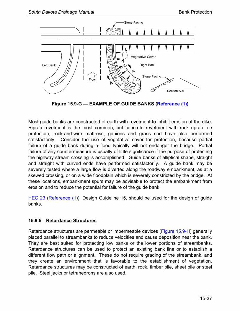
Guide banks (Figure 15.9-G) are used to prevent erosion at bridge abutments or piers. Guide banks were formerly referred to as spur dikes, which is now the term used for dikes perpendicular to the streambank. Without a guide bank, floodplain flow travels along the upstream side of an approach embankment and causes erosion where it enters the main flow at the bridge. By establishing smooth parallel streamlines in the approaching flow, guide banks improve flow conditions in the bridge waterway. Scour, if it occurs, is near the upstream end of the guide bank away from the bridge.
A guide bank differs from a dike in that a dike is intended to contain overbank flow, but a guide bank only seeks to align overbank flow with flow through the bridge opening. An extension of the usual concept of the guide bank is the use of guide banks and highway fill to constrict braided channels to one channel. Guide banks only or guide banks plus revetment on the highway fill can be used to constrict wide braided channels rather severely. Their performance can be affected by construction materials, shape, orientation and length.
South Dakota Drainage Manual Bank Protection
15-37
Figure 15.9-G — EXAMPLE OF GUIDE BANKS (Reference (1)) Most guide banks are constructed of earth with revetment to inhibit erosion of the dike. Riprap revetment is the most common, but concrete revetment with rock riprap toe protection, rock-and-wire mattress, gabions and grass sod have also performed satisfactorily. Consider the use of vegetative cover for protection, because partial failure of a guide bank during a flood typically will not endanger the bridge. Partial failure of any countermeasure is usually of little significance if the purpose of protecting the highway stream crossing is accomplished. Guide banks of elliptical shape, straight and straight with curved ends have performed satisfactorily. A guide bank may be severely tested where a large flow is diverted along the roadway embankment, as at a skewed crossing, or on a wide floodplain which is severely constricted by the bridge. At these locations, embankment spurs may be advisable to protect the embankment from erosion and to reduce the potential for failure of the guide bank.
HEC 23 (Reference (1)), Design Guideline 15, should be used for the design of guide banks.
15.9.5 Retardance Structures
Retardance structures are permeable or impermeable devices (Figure 15.9-H) generally placed parallel to streambanks to reduce velocities and cause deposition near the bank. They are best suited for protecting low banks or the lower portions of streambanks. Retardance structures can be used to protect an existing bank line or to establish a different flow path or alignment. These do not require grading of the streambank, and they create an environment that is favorable to the establishment of vegetation. Retardance structures may be constructed of earth, rock, timber pile, sheet pile or steel pile. Steel jacks or tetrahedrons are also used.

South Dakota Drainage Manual Bank Protection
15-38
Figure 15.9-H ⎯ TIMBER PILE RETARDANCE STRUCTURE (Reference (1)) HEC 23 (Reference (1)), Chapter 3, provides general guidance on the suitability of these types of structures. Consult Volume 1 of Reference (14) to determine the case site numbers for retardance structures. The actual case site histories are found in Volume 2.
15.9.6 Bulkheads
A bulkhead is a steep or vertical wall used to support a slope and/or protect it from erosion. Bulkheads usually project above ground, although the distinction between bulkheads and cutoff walls is not always clear. Bulkheads are used to support the channel bank and protect it from erosion. They are generally used as protection for the lower bank and toe, often in combination with other countermeasures that provide protection for higher portions of the bank.
Bulkheads are most frequently used at bridge abutments as protection against slumping and undermining at locations where there is insufficient space for the use of other types of bank stabilization measures, and where saturated fill slopes or channel banks cannot otherwise be stabilized. Bulkheads are classified on the basis of construction methods

South Dakota Drainage Manual Bank Protection
15-39
and materials. They may be constructed of concrete, masonry, cribs, sheet metal, piling, reinforced earth, gabions or other materials. They should be protected against scour or supported at elevations below anticipated total scour and, where sections of the installation are intermittently above water, provisions should be made for seepage through the wall. Some bulkhead types, such as crib walls (Figure 15.9-I) and gabions, should be provided with safeguards against the leaching of materials from behind the wall.
Bulkheads should be designed to resist the forces of overturning, bending and sliding, either by their mass or by structural design. Because of their costs, bulkheads should be used as countermeasures against meander migration only where space is not available to construct other channel stabilization methods.
Most bulkhead applications are at abutments and are most useful at the following locations:
• on braided streams with erodible sandy banks;
• where banks or abutment fill slopes have failed by slumping; and
• where stream alignment with the bridge opening is poor, which provides a transition between streambanks and the bridge opening.
Consult Volume 1 of (Reference (14)) to determine the case site numbers for bulkheads. The actual case site histories are found in Volume 2.
Figure 15.9-I — CONCRETE OR TIMBER CRIB BULKHEAD (Reference (16))

South Dakota Drainage Manual Bank Protection
15-40
15.10 REFERENCES
(1) Federal Highway Administration, Bridge Scour and Stream Instability Countermeasures, Experience, Selection and Design Guidance, Hydraulic Engineering Circular No. 23, FHWA-NHI-09-011 (Volume 1), FHWA-NHI-09-012 (Volume 2), Washington DC, 2009.
(2) Federal Highway Administration, Stream Stability at Highway Structures Third Edition, Hydraulic Engineering Circular No. 20, FHWA NHI-01-002, Washington DC, 2001.
(3) Federal Highway Administration, Design of Riprap Revetment, Hydraulic Engineering Circular No. 11, FHWA-IP-89-016, Washington DC, 1989.
(4) Barnes, H.H., Jr., “Roughness Characteristics of Natural Channels,” USGS Water Supply Paper 1849, Washington DC, 1978.
(5) US Army Corps of Engineers (USACE), Engineering Manual No. 1110-2-1601 (EM-1601), Engineering and Design — Hydraulic Design of Flood Control Channels, July 1991, Change 1-30, June 1994.
(6) Federal Highway Administration, Geosynthetic Design and Construction Guidelines, Participant Notebook, FHWA-HI-95-038, Washington, DC, 1995, Revised 1998.
(7) Freeman, G., and Fischenich, C., Gabions for Streambank Erosion Control, US Army Corps of Engineers, Environmental Laboratory, Ecosystem Management and Restoration Research Program (EMRRP), Technical Note (TN), Stream Restoration (SR) Number 22, EMRRP-SR-22, 2000.
(8) Maynord, S., Hebler, M., and Knight, S., User’s Manual, CHANLPRO, Technical Report CHL-98-20, US Army Engineer Waterways Experiment Station, Vicksburg, MS, 1998.
(9) Ayres Associates, Harris County Flood Control District, Design Manual for Articulating Concrete Block Systems, Project No. 32-0366.00, Fort Collins, CO, 2001.
(10) Kilgore, R.T., and Cotton, G.K., Design of Roadside Channels with Flexible Linings, Hydraulic Engineering Circular No. 15, 3rd Edition, FHWA-IF-05-114, Washington DC, 2005.
(11) Maynord, S.T., Gabion-Mattress Channel — Protection Design, ASCE Journal of Hydraulic Engineering, Vol. 1221, No. 7, 1995.
(12) Lagasse, P.F., Clopper P.E., Zevenbergen, L.W., and Girard, L.G., Countermeasures to Protect Bridge Piers from Scour, NCHRP Report 593, 2007.

South Dakota Drainage Manual Bank Protection
15-41
(13) Simons, D.B., Chen, Y.H., and Swenson, L.J., Hydraulic Test to Develop Design Criteria for the Use of Reno Mattresses, Maccaferri Steel Wire Products, LTD, Ontario, Canada, Civil Engineering Department, Colorado State University, Fort Collins, CO, 1984.
(14) Brice, J.C. and Blodgett, J.C., “Countermeasure for Hydraulic Problems at Bridges,” Volumes 1 and 2, FHWA-RD-78-162 and 163, USGS, Menlo Park, CA, 1978.
(15) Federal Highway Administration, Hydraulic Design of Energy Dissipators for Culverts and Channels, Hydraulic Engineering Circular No. 14, Third Edition, FHWA-NHI-06-086, 2006.
(16) Federal Highway Administration, River Engineering for Highway Encroachments — Highways in the River Environment, Hydraulic Design Series No. 6, FHWA-NHI-01-004, December 2001.

South Dakota Drainage Manual Bank Protection
15-42