chapter 16 configuring...
TRANSCRIPT

Chapter 16Configuring AppleTalk
This chapter describes how to configure AppleTalk on HP ProCurve 9304M, 9308M, and 6308M-SX routing switches using the CLI and the Web management interface. The routing switches support Phase II of AppleTalk routing.
For complete syntax information for the CLI commands shown in this chapter, see “Command Line Interface Commands” on page B-1.
NOTE: In addition to the routing features described in this chapter, the routing switches support AppleTalk cable VLANs. If you configure multiple cable VLANs, the routing switch bridges traffic within a VLAN and routes traffic between VLANs. See “Configuring AppleTalk Cable VLANs” on page 17-32.
Overview of AppleTalk
AppleTalk inter-networks are built upon distinct networks interconnected by routers. Each network is composed of nodes—workstations, printers, and servers. AppleTalk zones are assigned across AppleTalk networks to further define end-user access to shared resources such as printers and servers.
Address AssignmentAppleTalk node addresses are assigned dynamically. When a Macintosh running AppleTalk starts up, it selects a network address and checks to see if that address is already in use. If the address is already in use by another client, a message will be returned to the requesting station and the process will repeat until an uncommitted address is located.
Network ComponentsNodes
The node is the primary building block of any AppleTalk network. A node is any device on an AppleTalk network such as a workstation, printer, or server running AppleTalk.
Networks
Multiple nodes that share the same logical segment comprise an AppleTalk network. Each node in the network is assigned an AppleTalk address.
An AppleTalk address is comprised of a 16-bit network number and an 8-bit node number. For example, 500.50 refers to node 50 on network 500.
An AppleTalk network address is a single 16-bit network number or a network range (cable range). The network range specifies a range of contiguous network numbers with start and end values.
16-1

Advanced Configuration and Management Guide
Zones
AppleTalk zones are logical groupings of AppleTalk nodes defined within and across multiple networks as shown in Figure 16.1. For example, the Finance zone comprises two separate networks, 500 and 600. These network numbers are assigned to a specific interface on a router, and nodes within those networks are automatically assigned numbers in that range.
Defining zones for certain workstations and resources on the network allows you to easily permit or deny access to certain devices or information on the network by providing or hiding information about zones to a node or network. This is further explained in the following sections on filtering.
Figure 16.1 AppleTalk Zones defined within and across AppleTalk networks
Zone FilteringZone filtering allows you to define access for a network and its nodes by defining single permit or deny filters, rather than defining an access list for each node independently.
By eliminating the need to enter separate numbers for each device or network segment, zone filters improve overall system administration of an AppleTalk network. For example, if a new device such as a server or laser
16-2
Configuring AppleTalk
printer is added to an existing zone, all users in that zone automatically have access to that device without any additional configuration.
Additionally, this feature helps eliminate unauthorized access to devices within restricted zones. As new devices are added to secured zones, information on those devices is protected automatically.
Network FilteringYou also can filter on a network basis by enabling the Routing Table Maintenance Protocol (RTMP) filtering capability of zone filtering. When this filter is enabled on an interface, the denied network numbers are removed from the RTMP packet before it is transmitted out of the interface.
You can define deny or permit zone and network filters for AppleTalk on an interface basis. You can define up to 32 filters for routing switches operating with 32MB of memory. For those systems with 8MB of memory installed, you can define up to 16 filters.
Seed and Non-Seed RoutersAn AppleTalk router must be configured as either a seed or a non-seed router.
When you configure an AppleTalk router as a seed router, you must define the cable-range, address, and zone names for the router. When you configure a non-seed router, the router will learn its parameters from a seed AppleTalk router on the same segment.
AppleTalk Components Supported on the 9304M, 9308M, and 6308M-SX Routing Switches
The following sections describe the AppleTalk protocol components supported by the 9304M, 9308M, and 6308M-SX routing switches.
Session Layer SupportThe Zone Information Protocol (ZIP) maintains the mapping between defined network numbers and zone names within an AppleTalk network. This information is stored on a router in the zone information table.
ZIP also uses information from the RTMP routing table to stay current on the network topology.
Transport Layer Support Routing Table Maintenance Protocol (RTMP)
RTMP establishes and maintains the AppleTalk routing table. AppleTalk routers use RTMP to exchange routing information at regular intervals to ensure that each router has the latest routing information.
The periodic updates are sent out every 10 seconds by default.
AppleTalk Echo Protocol (AEP)
AppleTalk routers use AEP to check connectivity to other devices on the network.
AppleTalk Transaction Protocol (ATP)
ATP facilitates transaction-based applications. ATP supports a client/server design in which clients request information and servers reply with a response to that request. The protocol assigns a transaction ID to each request/response pair and allows only one instance of that specific transaction.
A sub-set of ATP is implemented to support ZIP on the 9304M, 9308M, and 6308M-SX routing switches.
Name Binding Protocol (NBP)
NBP maps AppleTalk names used on a network with addresses. For example, a printer for the marketing group may be named MKTG with an address of 100.5. This association is mapped together by the NBP.
NBP is dynamically initiated when the node is started. NBP also addresses registration, deletion, confirmation, and search of names.
16-3
Advanced Configuration and Management Guide
Network Layer SupportDatagram Delivery Protocol (DDP)
DDP provides connectionless service between application sockets on an AppleTalk network and administers AppleTalk addresses.
AppleTalk Address Resolution Protocol (AARP)
AARP translates AppleTalk addresses into 48-bit data link addresses. The 48-bit data link address is required in order to send AppleTalk packets to a specific node. AARP is also used to check for duplicate AppleTalk addresses on the network.
An AARP entry notes the mapping between a node’s AppleTalk address and its MAC (hardware) address.
Data Link SupportAppleTalk supports the EtherTalk Link Access Protocol (ELAP), which defines the layer 2 encapsulation for AppleTalk packets.
Dynamic AppleTalk Activation and ConfigurationAppleTalk is automatically activated when you enable the protocol on systems running software release 4.0 or later. On platforms running an earlier software release, you must reset the system to initially enable AppleTalk; however, all changes after that occur dynamically.
Configuring AppleTalk Routing
To begin using AppleTalk on a routing switch, perform the following tasks:
1. Enable AppleTalk on the routing switch, if it is not already enabled.
2. Configure AppleTalk as either a seed or a non-seed router.
When you configure a seed router, you define the cable-range, address, and zone names for the router. When you configure a non-seed router, the router will learn its parameters from another AppleTalk router on the same segment.
3. Define zone and additional zone filters, if desired.
4. Configure virtual interfaces to allow routing between AppleTalk VLANs, if desired.
5. Modify global parameters, if desired.
Enable AppleTalkTo enable AppleTalk routing on a routing switch, use one of the following methods.
NOTE: Once AppleTalk is enabled at the global (system) level, no additional configuration is required at this level unless the default parameters assigned need to be modified to address network requirements. See “Modifying AppleTalk Global Parameters” on page 16-24.
USING THE CLI
HP9300(config)# router appletalk
HP9300(config)# write mem
HP9300(config)# end
syntax: router appletalk
16-4

Configuring AppleTalk
USING THE WEB MANAGEMENT INTERFACE
1. Enable AppleTalk on the System configuration sheet.
2. Select the Apply button to assign the changes.
3. Select the Save To Flash link from the main menu to save the changes to flash.
Configuring a Seed AppleTalk RouterWhen you configure an AppleTalk router as a seed router, you must define the cable range, AppleTalk address, and zone names for the router interfaces.
To configure a seed router, perform the following tasks:
1. Configure the cable range (network numbers) to be supported on that interface.
2. Assign an AppleTalk address to the interface.
3. Assign a zone or zones to the interface.
4. Enable AppleTalk routing on the interface.
NOTE: Before configuring interface parameters for AppleTalk, you must enable AppleTalk at the system level.
USING THE CLI
This section describes defining a cable range, assigning network addresses and zones, and enabling AppleTalk routing on an interface.
Configuring the Cable Range for an Interface
To support network numbers from 10 – 50 on interface 1/3, enter the following commands:
HP9300(config)# int e 1/3
HP9300(config-if-1/3)# appletalk cable 10 - 50
syntax: appletalk cable <network number | network number - network number>
Configuring a Network Address for an Interface
To assign an AppleTalk address of 10.5 to interface 1/3, enter the following command:
HP9300(config-if-3)# appletalk address 10.5
Syntax: appletalk address <node.network>
Configuring Zones on an Interface
To assign sales, marketing, and finance zones for interface 1/3, enter the following commands:
HP9300(config-if-1/3)# appletalk zone sales
HP9300(config-if-1/3)# appletalk zone marketing
HP9300(config-if-1/3)# appletalk zone finance
NOTE: You can configure up to 1536 zones on a routing switch.
Enabling AppleTalk Routing on an Interface
To enable AppleTalk routing on interface 1/3, enter the following command:
HP9300(config-if-1/3)# appletalk routing
16-5

Advanced Configuration and Management Guide
Saving Configuration Changes to the Interface
Once you have configured the cable range, network address, zone(s), and AppleTalk routing for an interface, you can preserve the configuration changes by saving them to flash.
HP9300(config-if-1/3)# write mem
HP9300(config-if-1/3)# end
HP6308# reload
NOTE: When there is more than one seed router on the network, make sure the AppleTalk configuration of each of those seed routers is consistent with other routers on the same segment.
USING THE WEB MANAGEMENT INTERFACE
This section describes how to enable AppleTalk on the routing switch as well as how to configure the cable range, network address, and zones for an AppleTalk seed router.
To enable AppleTalk on the routing switch:
1. Select the System link from the main menu.
2. Enable the AppleTalk routing protocol.
3. Select the Apply button to assign the changes.
To configure an interface as a seed router:
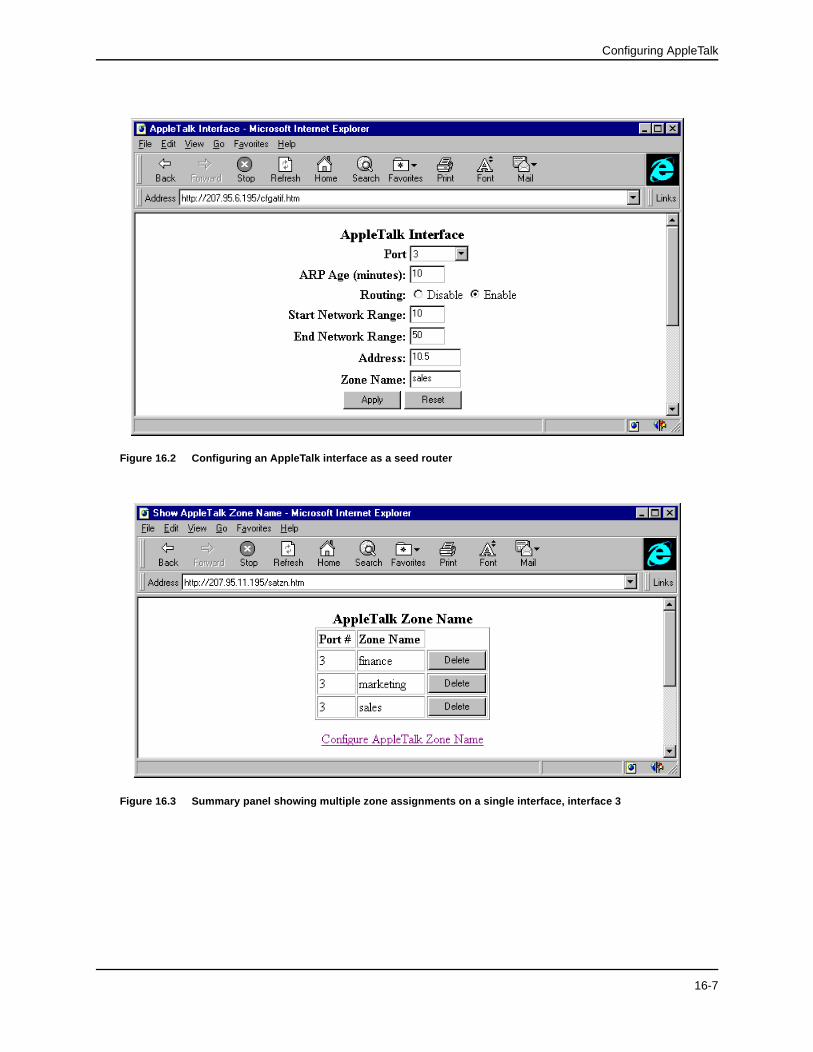
1. Select AppleTalk Interface from the AppleTalk configuration sheet to display the panel shown in Figure 16.2.
NOTE: If at least one AppleTalk is defined on the system, a summary panel will appear first. In this case, select the Configure AppleTalk Interface link.
2. Select the port or slot/port to be configured from the port pulldown menu(s).
3. Modify the ARP age value from the default value of 10 minutes, if desired. Possible values are 1 – 240 min-utes.
4. Enable the routing option.
5. Configure the range of supported network addresses by entering the lowest supported number in the Start Network Range field and the highest supported number in the End Network Range.
6. Enter the AppleTalk address for the port. The address should be a two decimal number, and the first number should be within the network range entered in step 5 above.
7. Enter a zone name for the port.
NOTE: To enter multiple zone names for a port, select the Configure Zone Name link at the bottom of the entry panel. A separate entry panel for that interface will appear. Enter the name(s) of the other zone(s) on an individual basis, selecting the Add button after each entry. For this example, a summary panel shows the resulting configuration (Figure 16.3).
NOTE: If you do not enter any values other than zero in the network range or address field, and the zone name field is empty, the routing switch will be a non-seed router.
8. Select the Apply button to assign the changes.
16-6
Configuring AppleTalk
Figure 16.2 Configuring an AppleTalk interface as a seed router
Figure 16.3 Summary panel showing multiple zone assignments on a single interface, interface 3
16-7

Advanced Configuration and Management Guide
Configuring a Non-seed AppleTalk RouterThis section describes how to configure a non-seed router using the CLI or the Web management interface.
To configure a non-seed router, perform the following tasks:
1. Verify that at least one AppleTalk router in the network of the routing switch being configured is operating as a seed router.
NOTE: This requirement ensures that the non-seed router has a seed router on the same segment, from which it can learn configuration details.
2. Enable AppleTalk at the global level.
3. Enable AppleTalk routing on the interface(s).
Enabling AppleTalk Routing at the Global (System) LevelTo enable AppleTalk on the routing switch, use one of the following methods:
USING THE CLI
HP9300(config)# router appletalk
USING THE WEB MANAGEMENT INTERFACE
1. Select the System link from the main menu.
2. Enable AppleTalk.
3. Select the Apply button to assign the change.
Enable AppleTalk Routing on an InterfaceTo enable AppleTalk on interface 1/5, use one of the following methods.
USING THE CLI
HP9300(config)# int e 1/5
HP9300(config-if-1/5)# appletalk routing
HP9300(config-if-1/5)# end
HP9300# write memory
HP9300# reload
NOTE: By definition, values for the network range, AppleTalk address, and zone name fields are never entered for a non-seed router. If you enter information into these fields, the routing switch is a seed router.
NOTE: Once configured as a non-seed router, the routing switch will send out a query to a seed router on its net-work to obtain configuration details such as network range, AppleTalk address, and zone name(s) for the routing switch.
16-8

Configuring AppleTalk
USING THE WEB MANAGEMENT INTERFACE
To configure an interface as a non-seed router:
1. Select AppleTalk Interface from the AppleTalk configuration sheet. The entry panel shown in Figure 16.4 will appear.
2. Select the port or slot/port to be configured from the pulldown menu(s).
3. Modify the ARP age value from the default value of 10 minutes, if desired. Possible values are 1 – 240 minutes.
4. Enable the routing option.
5. Select the Apply button to assign the changes.
Figure 16.4 Configuring an AppleTalk interface as a non-seed router
16-9
Advanced Configuration and Management Guide
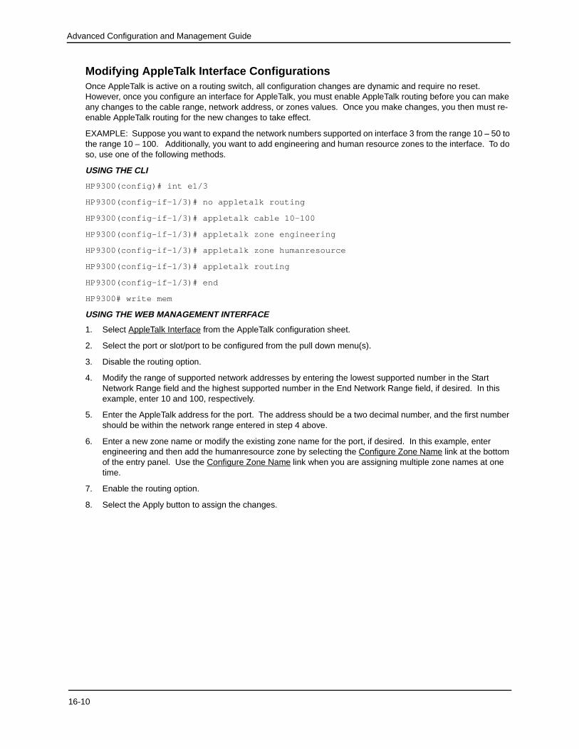
Modifying AppleTalk Interface ConfigurationsOnce AppleTalk is active on a routing switch, all configuration changes are dynamic and require no reset. However, once you configure an interface for AppleTalk, you must enable AppleTalk routing before you can make any changes to the cable range, network address, or zones values. Once you make changes, you then must re-enable AppleTalk routing for the new changes to take effect.
EXAMPLE: Suppose you want to expand the network numbers supported on interface 3 from the range 10 – 50 to the range 10 – 100. Additionally, you want to add engineering and human resource zones to the interface. To do so, use one of the following methods.
USING THE CLI
HP9300(config)# int e1/3
HP9300(config-if-1/3)# no appletalk routing
HP9300(config-if-1/3)# appletalk cable 10-100
HP9300(config-if-1/3)# appletalk zone engineering
HP9300(config-if-1/3)# appletalk zone humanresource
HP9300(config-if-1/3)# appletalk routing
HP9300(config-if-1/3)# end
HP9300# write mem
USING THE WEB MANAGEMENT INTERFACE
1. Select AppleTalk Interface from the AppleTalk configuration sheet.
2. Select the port or slot/port to be configured from the pull down menu(s).
3. Disable the routing option.
4. Modify the range of supported network addresses by entering the lowest supported number in the Start Network Range field and the highest supported number in the End Network Range field, if desired. In this example, enter 10 and 100, respectively.
5. Enter the AppleTalk address for the port. The address should be a two decimal number, and the first number should be within the network range entered in step 4 above.
6. Enter a new zone name or modify the existing zone name for the port, if desired. In this example, enter engineering and then add the humanresource zone by selecting the Configure Zone Name link at the bottom of the entry panel. Use the Configure Zone Name link when you are assigning multiple zone names at one time.
7. Enable the routing option.
8. Select the Apply button to assign the changes.
16-10

Configuring AppleTalk
Filtering AppleTalk Zones and Networks
Defining Zone FiltersZone filtering allows you to define access for a network and its nodes by entering single permit or deny CLI commands, instead of defining an access list for each node independently.
By eliminating the need to enter separate numbers for each device or network segment, zone filters improve overall system administration of an AppleTalk network. For example, if a new device such as a server or laser printer is added to an existing zone, all users in that zone automatically have access to that device without any additional configuration.
Additionally, zone filters help eliminate unauthorized access to devices within restricted zones. As new devices are added to secured zones, information on those devices is protected automatically.
Figure 16.5 AppleTalk zones in a network
16-11

Advanced Configuration and Management Guide
EXAMPLE: Suppose you want to deny access to the Finance server to users within the Marketing and Field Service zones on the network, as shown in Figure 16.5. To define a zone filter for this, use one of the following methods.
USING THE CLI
HP9300(config)# interface e1/1
HP9300(config-if-1/1)# appletalk deny zone finance
HP9300(config-if-1/1)# int e1/3
HP9300(config-if-1/3)# appletalk deny zone finance
HP9300(config-if-1/3)# int e1/13
HP9300(config-if-1/13)# appletalk deny zone finance
HP9300(config-if-1/13)# int e1/15
HP9300(config-if-1/15)# appletalk deny zone finance
USING THE WEB MANAGEMENT INTERFACE
1. Select Zone Filter from the AppleTalk configuration sheet. The panel shown in Figure 16.6 will appear.
2. Select the interface for which a zone filter is to be defined, from the port or slot/port pull down menu(s). In this example, you are defining a zone filter for interfaces 1, 3, 13, and 15, all of which have membership in either or both of the Marketing and Field Service zones.
3. Enter the name of the zone to which you are permitting or denying access. In this case, enter Finance.
4. Select either Deny or Permit. In this example, select Deny for interfaces 1, 3, 13, and 15.
5. Enable RTMP filtering to filter on a network basis. When RTMP filtering is enabled on an interface, the denied network numbers are removed from the RTMP packet before it is transmitted out of the interface.
6. Select the Add button to assign the filter.
NOTE: To view a summary of all the defined zone filters, select the Show AppleTalk Filter link on the Apple-Talk Zone Filter entry panel.
Figure 16.6 AppleTalk zone and network filter entry panel
16-12

Configuring AppleTalk
Define Additional Zone Filters
When defining AppleTalk zone filters, you must define both deny and permit relationships for an interface. For instance, in the previous example, a deny filter prevents users within Marketing and Field Service zones from accessing the Finance zone.
Because all additional zones not specifically addressed by a deny filter are permitted by default, you do not need to configure any specific permit definitions, and the requirement of defining both deny and permit relationships is satisfied.
However, the additional zone filter is useful in denying access to those zones not specifically addressed in permit zone filters. Consider the following example.
EXAMPLE: Suppose Sales, Human Resources (HR), Engineering, and Training zones will be added to the net-work in the next month. You know in advance that the only other zone that will be allowed access to the Finance zone is the HR zone.
You can configure permit zone filters (Figure 16.7) for ports 4/10 and 4/14 that allow the HR zone to have access to the finance zone and deny access to all others with a deny additional zone filter (Figure 16.7). This approach addresses the current network and all future zone additions with no additional configuration.USING THE CLI
To define the permit filter for HR on ports 4/10 and 4/14, enter the following commands:
HP9300(config)# interface e 4/10
HP9300(config-if-4/10)# no appletalk routing
HP9300(config-if-4/10)# appletalk permit zone HR
HP9300(config-if-4/10)# deny additional-zones
HP9300(config-if-4/10)# appletalk routing
HP9300(config-if-4/10)# int e 4/14
HP9300(config-if-4/14)# no appletalk routing
HP9300(config-if-4/14)# appletalk permit zone HR
HP9300(config-if-4/14)# appletalk routing
HP9300(config-if-4/14)# write mem
NOTE: You must disable AppleTalk routing on any interface already operating with AppleTalk before making any modifications to the configuration, and then re-enable routing to activate the change.
USING THE WEB MANAGEMENT INTERFACE
To define the permit and deny filters discussed above:
1. Select Zone Filter from the AppleTalk configuration sheet.
2. Select the interface for which the zone filter is to be defined from the port or slot/port pull down menu(s). In this example, you are defining a permit zone filter for HR for interfaces 4/10 and 4/14, which have membership in the Finance zone.
3. Enter the zone name to which access is to be permitted or denied. In this case, the zone name is HR.
4. Select either Deny or Permit. In this example, select Permit for interfaces 4/10 and 4/14.
5. Enable RTMP filtering to also filter on a network basis.
NOTE: When this filter is enabled on an interface, the denied network numbers are removed from the RTMP packet before it is transmitted out of the interface. In this example, RTMP filtering is not desired, so this option default is left as disabled.
16-13

Advanced Configuration and Management Guide
6. Select the Add button to assign the filter.
7. Select Additional Zone Filter from the AppleTalk configuration sheet to display the panel shown in Figure 16.6.
8. Select the interface for which the zone filter is to be defined, from the port or slot/port pull down menu(s). In this example, define a deny zone filter for interfaces 4/10 and 4/14 to deny all other zones not specified in the permit zone filter (steps 1 – 6 above).
9. Select either Deny or Permit. For this example, select Deny for interfaces 4/10 and 4/14.
10. Disable RTMP filtering.
11. Select the Apply button to assign the additional zone filter.
NOTE: To view a summary of the newly defined zone filters, select the Show AppleTalk Additional Zone Filter link on the Additional Zone Filter entry panel.
Figure 16.7 Defining an AppleTalk permit filter for port 10
Network FilteringEXAMPLE: To deny access to the Finance server to users within the Marketing and Field Service zones on the network and to prevent information about the zone and the network numbers from being forwarded out of interface 1/1 (Figure 16.5), use one of the following methods.
USING THE CLI
HP6308(config-if-1/1)# appletalk deny zone finance rtmp-filtering
USING THE WEB MANAGEMENT INTERFACE
To enable RTMP filtering on an interface, define the filter as usual, then enable the RTMP filtering option on the AppleTalk zone filter entry panel shown in Figure 16.7.
16-14

Configuring AppleTalk
Routing Between AppleTalk VLANs Using Virtual InterfacesIn addition to supporting AppleTalk VLANs, the routing switches support routing between AppleTalk VLANs using virtual interfaces. The virtual interfaces provide VLANs access to the router functions of routing switches. Using these virtual interfaces eliminates the need to assign a physical port for routing between local VLANs.
AppleTalk routing between virtual and physical interfaces is also supported.
EXAMPLE 1: In Figure 16.8, AppleTalk traffic is terminating on ports 1/1 through 1/4. Suppose you want to group all of these interfaces into an AppleTalk protocol VLAN and route traffic to VLANs on other routing switches.
To do so, perform the following steps:
1. Create an AppleTalk protocol VLAN with port membership of ports 1, 2, 3, and 4.
2. Assign a virtual interface to the AppleTalk VLAN to allow it to route traffic to AppleTalk VLANs on remote rout-ing switches.
3. Configure a physical interface on the routing switch that provides access to remote networks to support rout-ing between local and remote AppleTalk VLANs.
NOTE: By supporting assignment of VLANs on interfaces, the routing switch is functioning as a virtual switch.
Figure 16.8 Virtual interface provides a routing interface to an AppleTalk VLAN
USING THE CLI
To configure the AppleTalk VLAN as seen in Figure 16.8, enter the following commands:
HP9300(config)# router appletalk
HP9300(config)# vlan 1
HP9300(config-vlan-1)# atalk-proto
� ��
�
�
�
�
Switch
RouterAppleTalkProtocol VLAN
9LUWXDO�,QWHUIDFH��
������)LQDQFH=RQH
������0DUNHWLQJ=RQH
16-15

Advanced Configuration and Management Guide
HP9300(config-vlan-atalk-proto)# static e1/1 to 1/4
HP9300(config-vlan-atalk-proto)# router-interface ve 3
To configure the physical interface (e 1/8) to which all outgoing traffic is forwarded, enter the following commands:
HP9300(config-vlan-atalk-proto)# int e1/8
HP9300(config-if-1/8)# appletalk cable-range 300 - 300
HP9300(config-if-1/8)# appletalk address 300.50
HP9300(config-if-1/8)# appletalk zone-name Finance
HP9300(config-if-1/8)# appletalk routing
To configure the defined AppleTalk VLAN virtual interface ve3, enter the following commands:
HP9300(config-if-1/8)# int ve 3
HP9300(config-vif-3)# appletalk cable-range 100 - 100
HP9300(config-vif-3)# appletalk address 100.50
HP9300(config-vif-3)# appletalk zone-name Marketing
HP9300(config-vif-3)# appletalk routing
USING THE WEB MANAGEMENT INTERFACE
To configure the AppleTalk VLAN shown in Figure 16.8:
1. Enable L3 protocol VLANs on the System configuration sheet, if not already enabled.
2. Select the VLAN link from the main menu. The VLAN configuration sheet will appear.
3. Select the Protocol VLAN link from the VLAN configuration sheet. The protocol VLAN entry panel shown in Figure 16.9 will appear.
4. Select AppleTalk as the protocol type.
5. Assign ports 1, 2, 3, and 4 as static.
6. Select v3 to be the virtual router interface for the VLAN.
7. Select the Add button to create the VLAN.
Figure 16.9 Defining physical and virtual interfaces for an AppleTalk protocol VLAN
16-16
Configuring AppleTalk
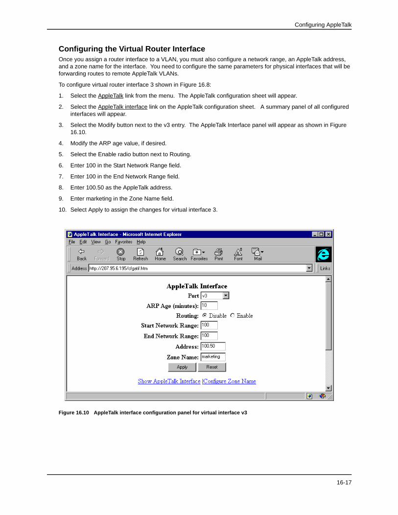
Configuring the Virtual Router InterfaceOnce you assign a router interface to a VLAN, you must also configure a network range, an AppleTalk address, and a zone name for the interface. You need to configure the same parameters for physical interfaces that will be forwarding routes to remote AppleTalk VLANs.
To configure virtual router interface 3 shown in Figure 16.8:
1. Select the AppleTalk link from the menu. The AppleTalk configuration sheet will appear.
2. Select the AppleTalk interface link on the AppleTalk configuration sheet. A summary panel of all configured interfaces will appear.
3. Select the Modify button next to the v3 entry. The AppleTalk Interface panel will appear as shown in Figure 16.10.
4. Modify the ARP age value, if desired.
5. Select the Enable radio button next to Routing.
6. Enter 100 in the Start Network Range field.
7. Enter 100 in the End Network Range field.
8. Enter 100.50 as the AppleTalk address.
9. Enter marketing in the Zone Name field.
10. Select Apply to assign the changes for virtual interface 3.
Figure 16.10 AppleTalk interface configuration panel for virtual interface v3
16-17

Advanced Configuration and Management Guide
Configuring a Physical Interface for Remote AccessTo support routing between the local AppleTalk VLAN and remote AppleTalk VLANs, define a physical interface that will forward outgoing traffic.
To configure interface 1/8 as shown in Figure 16.8:
1. Select the AppleTalk Interface link from the AppleTalk configuration sheet. A summary panel of all interfaces and their configurations will appear.
2. Select the Modify button next to the entry for port 8. The AppleTalk Interface entry panel for interface 1/8 shown in Figure 16.11 will appear.
3. Modify the ARP age default value of 10 minutes if desired. Possible values are 1 – 240 minutes.
4. Select the Enable radio button next to Routing.
5. Enter 300 as the start and end network range.
6. Enter 300.50, the AppleTalk address for the interface, in the Address field.
7. Enter finance in the Zone Name field.
8. Select the Apply button to assign the changes.
NOTE: If you modify the configuration after assigning the changes, you must first disable routing on an inter-face before entering the changes and then re-enable routing when the changes are complete.
Figure 16.11 AppleTalk interface entry panel for physical interface 1/8
16-18

Configuring AppleTalk
Routing Between Protocol VLANs Within Port-Based VLANs
In Figure 16.12, AppleTalk traffic is terminating on ports 1 – 4 on two separate networks, 100 and 200. Suppose you want to assign these networks to two separate VLANs but would also like to route traffic between the two VLANs and externally to the routing switch.
To create the configuration shown in Figure 16.12, perform the following tasks.
1. Create port-based VLANs 2 and 3.
NOTE: Protocol VLANs must always be within the boundaries of a port-based domain. Whenever port and protocol VLANs operate on a system together, you must create the port-based VLAN before you create the protocol VLAN. The protocol-based VLAN overlays the port-based VLAN.
2. Create AppleTalk protocol VLANs 2 and 3.
3. Configure router interfaces virtual 3 (v3) and virtual 5 (v5).
4. Configure physical interface port 8.
NOTE: Each of the above tasks is described in the following sections.
Figure 16.12 Routing between AppleTalk VLANs
USNG THE CLI
HP9300(config)# vlan 2 by port
HP9300(config-vlan-2)# untag e1/3 to 1/4
HP9300(config-vlan-2)# atalk-proto
HP9300(config-vlan-atalk-proto)# static e1/3 to 1/4
HP9300(config-vlan-atalk-proto)# router-interface ve 5
HP9300(config-vlan-atalk-proto)# end
� �� �
9LUWXDO��
9LUWXDO��
Switch
Router
Port-based VLAN 2
Port-based VLAN 3
�
�
AppleTalk Protocol VLAN
AppleTalk Protocol VLAN
�
�
������
6DOHV
=RQH
������
0DUNHWLQJ
=RQH
1HWZRUN����
1HWZRUN����
������
)LQDQFH
=RQH
16-19

Advanced Configuration and Management Guide
HP9300(config-vlan-2)# vlan 3 by port
HP9300(config-vlan-3)# untag e1/1 to 1/2
HP9300(config-vlan-3)# atalk-proto
HP9300(config-vlan-atalk-proto)# router-interface ve 3
To configure the physical interface (e8) to which all outgoing traffic is forwarded, enter the following commands:
HP9300(config-vlan-atalk-proto)# int e1/8
HP9300(config-if-1/8)# appletalk cable-range 400 - 400
HP9300(config-if-1/8)# appletalk address 400.50
HP9300(config-if-1/8)# appletalk zone-name sales
HP9300(config-if-1/8)# appletalk routing
To configure the defined AppleTalk VLAN virtual interfaces ve3 and ve5, enter the following commands:
HP9300(config-if-1/8)# int ve 5
HP9300(config-vif-5)# appletalk cable-range 100 - 100
HP9300(config-vif-5)# appletalk address 100.50
HP9300(config-vif-5)# appletalk zone-name finance
HP9300(config-vif-5)# appletalk routing
HP9300(config-vif-5)# int ve 3
HP9300(config-vif-3)# appletalk cable-range 200 - 200
HP9300(config-vif-3)# appletalk address 200.50
HP9300(config-vif-3)# appletalk zone-name marketing
HP9300(config-vif-3)# appletalk routing
HP9300(config-vif-3)# end
HP9300# write mem
USING THE WEB MANAGEMENT INTERFACE
To create port-based VLANs 2 and 3:
1. Verify that both port-based and L3 VLANs are enabled on the System configuration sheet.
2. Select the VLAN link. The port VLAN configuration sheet (Figure 16.13) will appear.
NOTE: If port or protocol VLANs are already configured on the system, the show port VLAN panel will appear. In this case, select the Add Port VLAN link to reach the Port -based VLAN configuration sheet.
NOTE: If any protocol VLANs are defined on the system, you need to delete them before you can configure port-based VLANs. When both port and protocol VLANs are to operate on a system together, you must define the port-based VLANs first.
3. Enter the value 2 into the VLAN ID field and enter a name, if desired. Assigning a name for the VLAN is optional, but you must enter a VLAN ID.
4. Select a value from 0 (low priority) – 7 (high priority) from the QOS pull down menu. In this example, no change is required, so the default value of 0 remains unchanged.
5. Assign a router interface if routing to another port-based VLAN is desired. In this example, a router interface is not assigned to the port-based VLAN but will be assigned at the protocol VLAN level.
6. Select 1/3 and 1/4 as port members.
16-20

Configuring AppleTalk
7. Select the Add button to create the port-based VLAN 2.
8. Enter the value of 3 into the VLAN ID field and select 1/1 and 1/2 as its members.
9. Repeat steps 4 and 5 above.
10. Select the Add button to create the port-based VLAN 3.
Figure 16.13 Creating port-based VLAN 2
Creating AppleTalk Protocol VLANsOnce you create port-based VLANs 2 and 3, you can assign the AppleTalk protocol VLANs. To assign the two protocol VLANs shown in Figure 16.12:
1. Select the Protocol VLAN link from the port VLAN panel to display the protocol VLAN configuration panel shown in Figure 16.14.
2. Enter 2 into the VLAN ID field.
3. Select AppleTalk as the protocol.
4. Assign ports 1/3 and 1/4 as static.
5. Assign v5 as the virtual interface by selecting that value from the Router Interface pull down menu.
6. Select Add to create an AppleTalk protocol VLAN within port-based VLAN 2.
7. Enter 3 into the VLAN ID field.
8. Select AppleTalk as the protocol.
9. Assign ports 1/1 and 1/2 as static.
10. Assign v3 as the virtual interface by selecting that value from the Router Interface pull down menu.
11. Select Add to create an AppleTalk protocol VLAN within port-based VLAN 3.
NOTE: You are now ready to configure the virtual (v3 and v5) and physical interfaces (port 8).
16-21

Advanced Configuration and Management Guide
Figure 16.14 Creating an AppleTalk protocol VLAN within port-based VLAN 2
Configuring the Router InterfacesOnce a router interface is assigned to a VLAN, it must also be configured with a network range, an AppleTalk address, and a zone name. The same will also need to be done for those physical interfaces that will be forwarding routes to remote AppleTalk VLANs.
To configure virtual router interfaces 3 and 5 shown in Figure 16.12:
1. Select the AppleTalk link from the menu. The AppleTalk configuration sheet will appear.
2. Select the AppleTalk Interface link on the AppleTalk configuration sheet. A summary panel of all configured interfaces will appear.
3. Select the Modify button next to the v3 entry. The AppleTalk interface panel (Figure 16.15) will appear.
4. Modify the ARP age, if desired.
5. Select the Enable radio button next to Routing.
6. Enter 200 in the Start Network Range field.
7. Enter 200 in the End Network Range field.
8. Enter 200.50 as the AppleTalk address.
9. Enter marketing in the Zone Name field.
10. Select Apply to assign the changes for virtual interface 3.
11. Select the Show AppleTalk Interface link. The summary panel of all AppleTalk interfaces will appear.
12. Select the Modify button next to the v5 entry. The AppleTalk interface panel will appear.
13. Modify the ARP age, if desired.
14. Select the Enable radio button next to Routing.
15. Enter 100 in the Start Network Range field.
16-22

Configuring AppleTalk
16. Enter 100 in the End Network Range field.
17. Enter 100.50 as the AppleTalk address.
18. Enter finance in the Zone Name field.
19. Select Apply to assign the changes for virtual interface 5.
NOTE: After performing this initial configuration, you need to disable routing on an AppleTalk interface before making any changes to the network range values, AppleTalk address, or zone name of that interface.
Figure 16.15 Configuring virtual interface v5
Configuring the Physical Interface for Remote AccessPhysical interface 1/8 in Figure 16.12 is the path for forwarding routes to remote AppleTalk VLANs, so you must configure this interface in addition to the virtual router interfaces.
To configure interface 1/8 shown in Figure 16.12:
1. Select the AppleTalk link from the menu. The AppleTalk configuration sheet will appear.
2. Select the AppleTalk Interface link. A summary panel of all interfaces will appear.
3. Select the Modify button next to the 1/8 entry. The AppleTalk interface panel will appear.
4. Modify the ARP age, if desired.
5. Select the Enable radio button next to Routing.
6. Enter 400 in the Start Network Range field.
7. Enter 400 in the End Network Range field.
8. Enter 400.50 as the AppleTalk address.
9. Enter sales in the Zone Name field.
10. Select Apply to assign the configuration.
16-23

Advanced Configuration and Management Guide
Modifying AppleTalk Global ParametersYou can modify the following AppleTalk parameters at the global level:
• AppleTalk ARP retransmission count
• AppleTalk ARP retransmission interval
• AppleTalk glean packets
• AppleTalk QoS socket (assigns a higher priority)
• AppleTalk RTMP update interval
• AppleTalk ZIP query interval
The following sections describe these parameters and show how to change them.
AppleTalk ARP Retransmit CountYou can modify the maximum number of times that a packet will be sent out for ARP cache informational updates. The packet is sent out to the maximum amount defined, until the information is received.
If no response is received before the count number expires, the routing switch does not send any additional packets. Possible values are from 1 – 10. The default is 2.
EXAMPLE: To modify the number of times packet requests are sent out for ARP updates from the default (2) to 8, use one of the following methods.
USING THE CLI
HP9300(config)# appletalk arp retransmit-count 8
syntax: appletalk arp retransmit-count <1-10>
USING THE WEB MANAGEMENT INTERFACE
1. Select AppleTalk from the main menu. The configuration sheet shown in Figure 16.16 will appear.
2. Enter a new ARP retransmit count from 1 – 10. For this example, enter 8.
3. Select the Apply button to assign the new value.
AppleTalk ARP Retransmit IntervalYou can modify the interval between the transmission of ARP packets. Possible values are from 1 – 120 seconds. The default is 1 second.
EXAMPLE: To modify the ARP retransmission interval from the default value (1) to 15 seconds, use one of the following methods.
USING THE CLI
HP9300(config)# appletalk arp retransmit-interval 15
syntax: appletalk arp retransmit-interval <1-120>
USING THE WEB MANAGEMENT INTERFACE
1. Select AppleTalk from the main menu. The configuration sheet shown in Figure 16.16 will appear.
2. Enter a new AppleTalk ARP Retransmit Interval from 1 – 120. For this example, enter 15.
3. Select the Apply button to assign the new value.
16-24

Configuring AppleTalk
AppleTalk Glean PacketsWhen you enable the glean packet parameter on an AppleTalk router, the router tries to learn the MAC address from the packet instead of sending out an ARP request. The glean packets parameter is disabled by default.
EXAMPLE: To enable glean packets, use one of the following methods.
USING THE CLI
HP9300(config)# appletalk glean-packets
syntax: appletalk glean-packets
USING THE WEB MANAGEMENT INTERFACE
1. Select AppleTalk from the main menu. The configuration sheet shown in Figure 16.16 will appear.
2. Enable glean packet.
3. Select the Apply button to assign the new value.
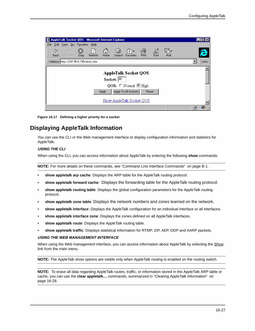
AppleTalk QoS SocketThe user can use the QoS socket parameter to assign a higher priority to specific AppleTalk sockets. Possible values are 0 (normal priority) to 7 (highest priority). The default value for all sockets is 0.
EXAMPLE: To assign a high priority to socket 123, use one of the following methods.
USING THE CLI
HP6308(config)# appletalk qos socket 123 priority 1
syntax: appletalk qos socket <number> priority <0-7>
USING THE WEB MANAGEMENT INTERFACE
1. Select the Socket QOS link from the AppleTalk configuration sheet. The panel shown in Figure 16.17 will appear.
2. Enter the number of the socket to be assigned a higher priority. For example, to assign a higher priority to all web traffic, enter the number 80 in this field as shown in Figure 16.17.
3. Select a value from 0 – 7 from the QoS pulldown menu. In this example, select 1.
4. Select the Apply button to assign the higher priority to the selected socket. Selecting Apply To All Sockets assigns the higher priority to all AppleTalk sockets on the routing switch.
AppleTalk RTMP Update IntervalYou can change the RTMP update interval to modify how often the routing switch sends RTMP updates on AppleTalk interfaces. Possible values are from 1 – 3600 seconds. The default is 10 seconds.
EXAMPLE: To change the value to 50 seconds from a default value of 10 seconds, use one of the following methods.
USING THE CLI
HP9300(config)# appletalk rtmp-update-interval 50
syntax: appletalk rtmp-update-interval <1-3600>
USING THE WEB MANAGEMENT INTERFACE
1. Select AppleTalk from the main menu. The configuration sheet shown in Figure 16.16 will appear.
2. Enter a new RTMP update interval from 1 – 3600. For this example, enter 50.
3. Select the Apply button to assign the new value.
16-25

Advanced Configuration and Management Guide
AppleTalk ZIP Query IntervalYou can change the ZIP query interval to modify how often the routing switch retransmits ZIP query messages. Possible values are from 1 – 1000 seconds. The default is 10 seconds.
EXAMPLE: To change the ZIP query interval to 30 seconds from the default value (10 seconds), use one of the following methods.
USING THE CLI
HP9300(config)# appletalk zip-query-interval 30
syntax: appletalk zip-query <1-1000>
USING THE WEB MANAGEMENT INTERFACE
1. Select AppleTalk from the main menu. The configuration sheet shown in Figure 16.16 will appear.
2. Enter a new ZIP query interval from 1 – 1000. For this example, enter 30.
3. Select the Apply button to assign the new value.
Figure 16.16 AppleTalk configuration sheet
16-26
Configuring AppleTalk
Figure 16.17 Defining a higher priority for a socket
Displaying AppleTalk Information
You can use the CLI or the Web management interface to display configuration information and statistics for AppleTalk.
USING THE CLI
When using the CLI, you can access information about AppleTalk by entering the following show commands.
NOTE: For more details on these commands, see “Command Line Interface Commands” on page B-1.
• show appletalk arp cache: Displays the ARP table for the AppleTalk routing protocol.
• show appletalk forward cache: Displays the forwarding table for the AppleTalk routing protocol.
• show appletalk routing table: Displays the global configuration parameters for the AppleTalk routing protocol.
• show appletalk zone table : Displays the network numbers and zones learned on the network.
• show appletalk interface: Displays the AppleTalk configuration for an individual interface or all interfaces.
• show appletalk interface zone: Displays the zones defined on all AppleTalk interfaces.
• show appletalk route: Displays the AppleTalk routing table.
• show appletalk traffic: Displays statistical information for RTMP, ZIP, AEP, DDP and AARP packets.
USING THE WEB MANAGEMENT INTERFACE
When using the Web management interface, you can access information about AppleTalk by selecting the Show link from the main menu.
NOTE: The AppleTalk show options are visible only when AppleTalk routing is enabled on the routing switch.
NOTE: To erase all data regarding AppleTalk routes, traffic, or information stored in the AppleTalk ARP table or cache, you can use the clear appletalk… commands, summarized in “Clearing AppleTalk Information” on page 16-28.
16-27
Advanced Configuration and Management Guide
Clearing AppleTalk InformationUSING THE CLI
When using the CLI, you can clear AppleTalk data by entering the following CLI commands:
• clear appletalk arp cache: Erases all data in the AppleTalk ARP table, as displayed by the show appletalk arp command.
• clear appletalk forward cache: Erases all learned data from non-local networks that is currently resident in the AppleTalk cache (forwarding table), as displayed by the show appletalk cache command.
• clear appletalk route : Erases all learned routes and zones (non-local routes and zones) currently resident in the AppleTalk routing table, as displayed by the show appletalk route command.
• clear appletalk statistics: Erases all RTMP, ZIP, AEP, DDP, and AARP statistics for the routing switch. You can display a summary of the statistics that will be erased by entering the show appletalk traffic command.
NOTE: For more details on these commands, see “Command Line Interface Commands” on page B-1.
USING THE WEB MANAGEMENT INTERFACE
You can clear AppleTalk data by selecting the appropriate link from the Clear panel. The AppleTalk clear options are visible only when AppleTalk routing is enabled on the routing switch.
You can access the clear panel be selecting the Clear link from the main menu.
16-28