chapter 2: dimensioning -...
TRANSCRIPT
Copyright ©2006 by K. Plantenberg
Restricted use only
Chapter 2:
Dimensioning
Basic Topics
Advanced Topics
Exercises
Copyright ©2006 by K. Plantenberg
Restricted use only
Dimensioning: Basic Topics
Summary
2-1) Detailed Drawings
2-2) Learning to Dimension
2-3) Dimension Appearance and Techniques.
2-4) Dimensioning and Locating Simple
Features.
2-6) Dimension Choice.
Copyright ©2006 by K. Plantenberg
Restricted use only
Dimensioning: Advanced Topics
2-5) Dimensioning and Locating Advanced
Features.
Copyright ©2006 by K. Plantenberg
Restricted use only
Dimensioning: Exercises
Exercise 2-1: Dimension type
Exercise 2-2: Spacing and readability 1
Exercise 2-3: Spacing and readability 2
Exercise 2-4: Duplicate dimensions
Exercise 2-5: Dimension placement
Exercise 2-6: Circular and rectangular views
Exercise 2-7: Dimensioning and locating features
Exercise 2-8: Advanced features
Exercise 2-9: Dimension accuracy
Exercise 2-10: Round off
Copyright ©2006 by K. Plantenberg
Restricted use only
Dimensioning: Exercises
Exercise 2-11: Dimension choice
Exercise 2-12: Dimensioning 1
Exercise 2-13: Dimensioning 2
Exercise 2-14: Dimensioning 3
Exercise 2-15: Dimensioning 4
Copyright ©2006 by K. Plantenberg
Restricted use only
Dimensioning
Summary
Copyright ©2006 by K. Plantenberg
Restricted use only
Dimensioning Summary
� What will we learn in Chapter 2?
→ How to dimension an orthographic
projection using proper dimensioning
techniques.
� Key points
→ Dimensions affect how a part is
manufactured.
Copyright ©2006 by K. Plantenberg
Restricted use only
Dimensioning
2-1) Detailed Drawings
Copyright ©2006 by K. Plantenberg
Restricted use only
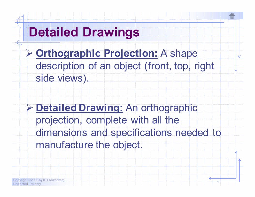
Detailed Drawings
� Orthographic Projection: A shape
description of an object (front, top, right
side views).
� Detailed Drawing: An orthographic
projection, complete with all the
dimensions and specifications needed to
manufacture the object.
Copyright ©2006 by K. Plantenberg
Restricted use only
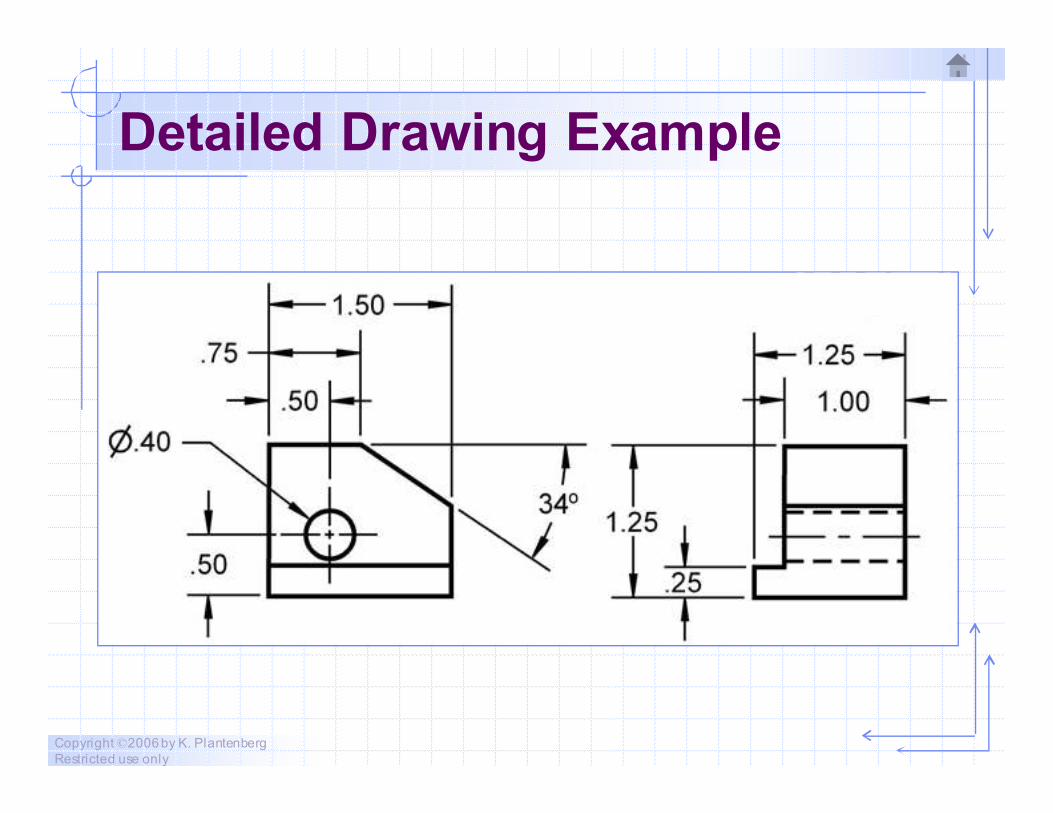
Detailed Drawing Example
Copyright ©2006 by K. Plantenberg
Restricted use only
Detailed Drawings
� Can we dimension an object using the
dimensions that we used to draw the
object?
No
These are not necessarily the same
dimensions required to manufacture it.
We need to follow accepted standards.
(ASME Y14.5 – 1994)
Copyright ©2006 by K. Plantenberg
Restricted use only
Dimensioning
2-2) Learning To Dimension
Copyright ©2006 by K. Plantenberg
Restricted use only
Learning to Dimension
� What is our goal when dimensioning a
part?
→ Basically, dimensions should be given in a
clear and concise manner and should
include everything needed to produce and
inspect the part exactly as intended by the
designer.
Copyright ©2006 by K. Plantenberg
Restricted use only
Learning to Dimension
� Proper dimensioning techniques
require the knowledge of the following
three areas.
→ Dimension Appearance/Technique
→ Dimensioning and Locating Features
→ Dimension Choice
Copyright ©2006 by K. Plantenberg
Restricted use only
Learning to Dimension
1. Dimension Appearance/Technique:
Dimensions use special lines, arrows,
symbols and text.
a) The lines used in dimensioning.
b) Types of dimensions.
c) Dimension symbols.
d) Dimension spacing and readability.
e) Dimension placement.
Copyright ©2006 by K. Plantenberg
Restricted use only
Learning to Dimension
2. Dimensioning and Locating Features:
Different types of features require unique
methods of dimensioning.
Copyright ©2006 by K. Plantenberg
Restricted use only
Learning to Dimension
3. Dimension Choice: Your choice of
dimensions will directly influence the
method used to manufacture the part.
a) Units and decimal places.
b) Locating feature using datums.
c) Dimension accuracy and error build up.
Copyright ©2006 by K. Plantenberg
Restricted use only
Dimensioning
2-3) Dimension Appearance
and Techniques
Copyright ©2006 by K. Plantenberg
Restricted use only
Lines used in Dimensioning
� Dimensioning requires the use of
→ Dimension lines
→ Extension lines
→ Leader lines
� All three line types are drawn thin so that
they will not be confused with visible lines.
Copyright ©2006 by K. Plantenberg
Restricted use only
Dimension Line
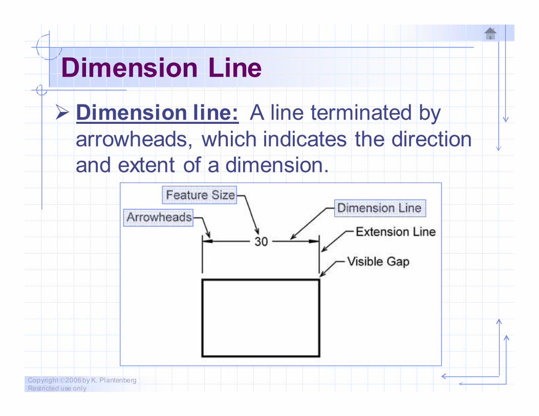
� Dimension line: A line terminated by
arrowheads, which indicates the direction
and extent of a dimension.
Copyright ©2006 by K. Plantenberg
Restricted use only
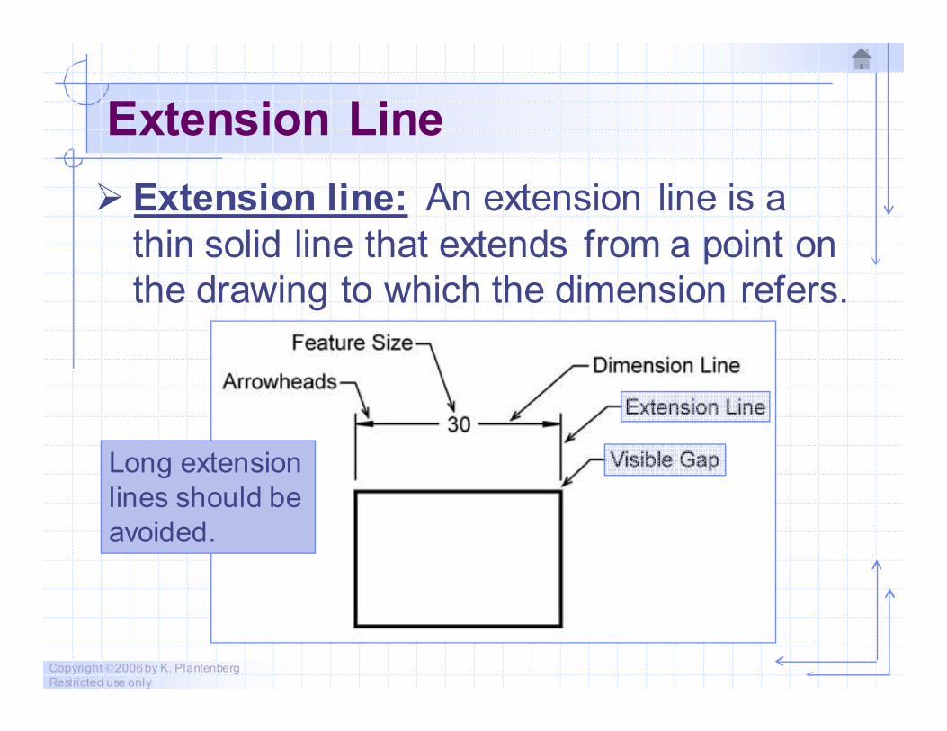
Extension Line
� Extension line: An extension line is a
thin solid line that extends from a point on
the drawing to which the dimension refers.
Long extension
lines should be
avoided.
Copyright ©2006 by K. Plantenberg
Restricted use only
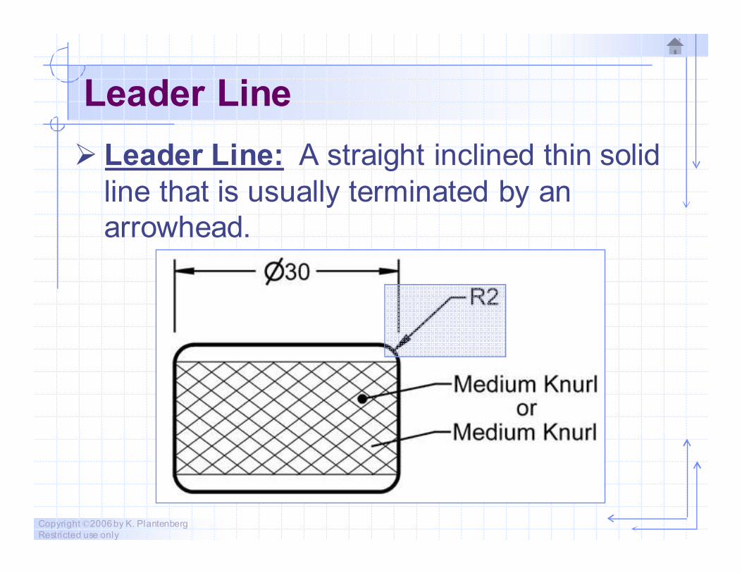
Leader Line
� Leader Line: A straight inclined thin solid
line that is usually terminated by an
arrowhead.
Copyright ©2006 by K. Plantenberg
Restricted use only
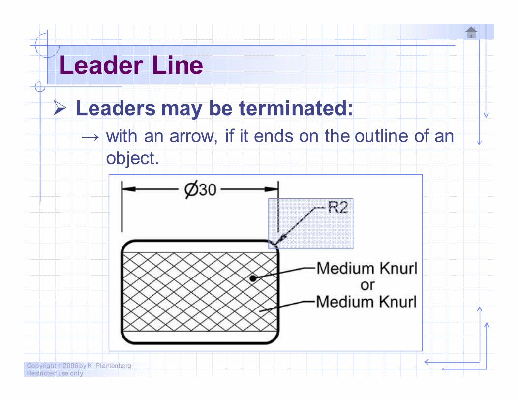
Leader Line
� Leaders may be terminated:
→ with an arrow, if it ends on the outline of an
object.
Copyright ©2006 by K. Plantenberg
Restricted use only
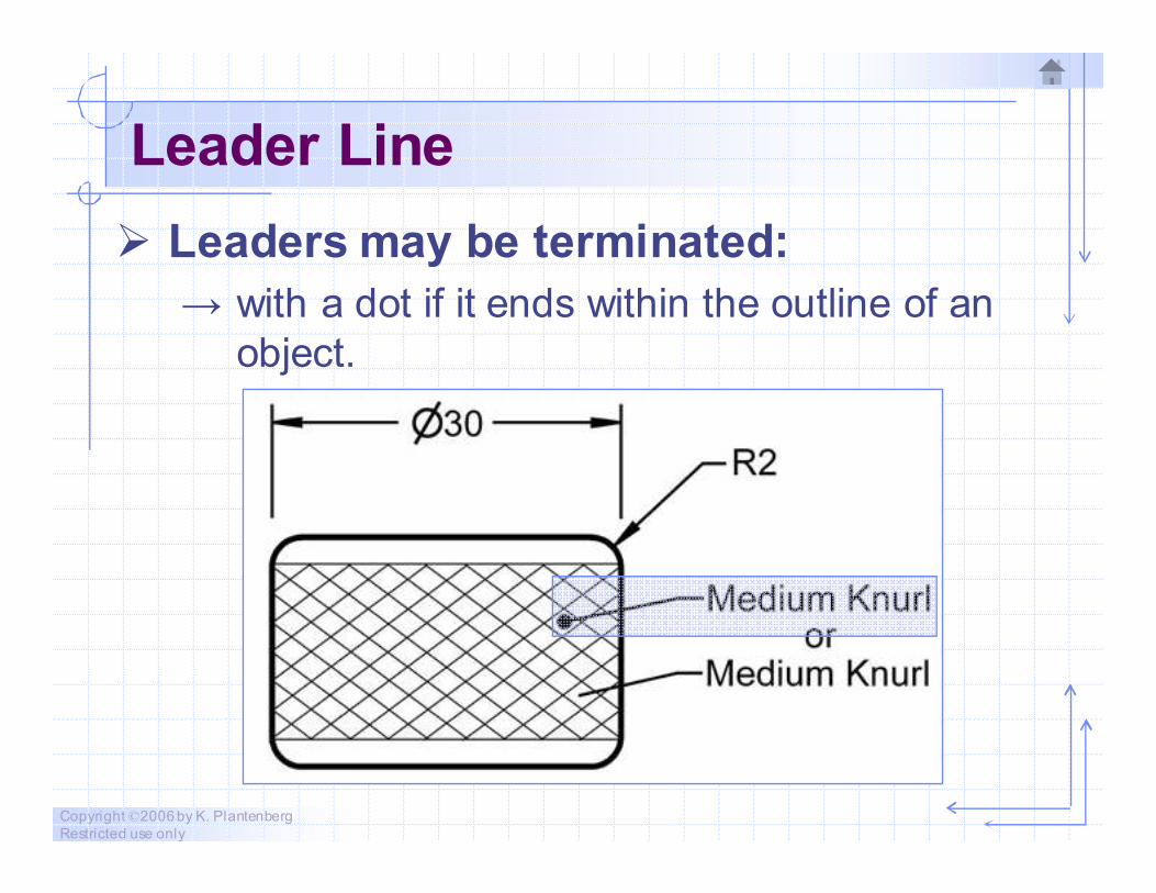
Leader Line
� Leaders may be terminated:
→ with a dot if it ends within the outline of an
object.
Copyright ©2006 by K. Plantenberg
Restricted use only
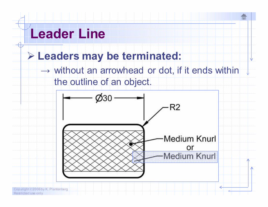
Leader Line
� Leaders may be terminated:
→ without an arrowhead or dot, if it ends within
the outline of an object.

Copyright ©2006 by K. Plantenberg
Restricted use only
Leader Line
� Avoid!
→ Crossing leaders.
→ Long leaders.
→ Leaders that are parallel to adjacent
dimension, extension or section lines.
→ Small angles between the leader and the
terminating surface.
Copyright ©2006 by K. Plantenberg
Restricted use only
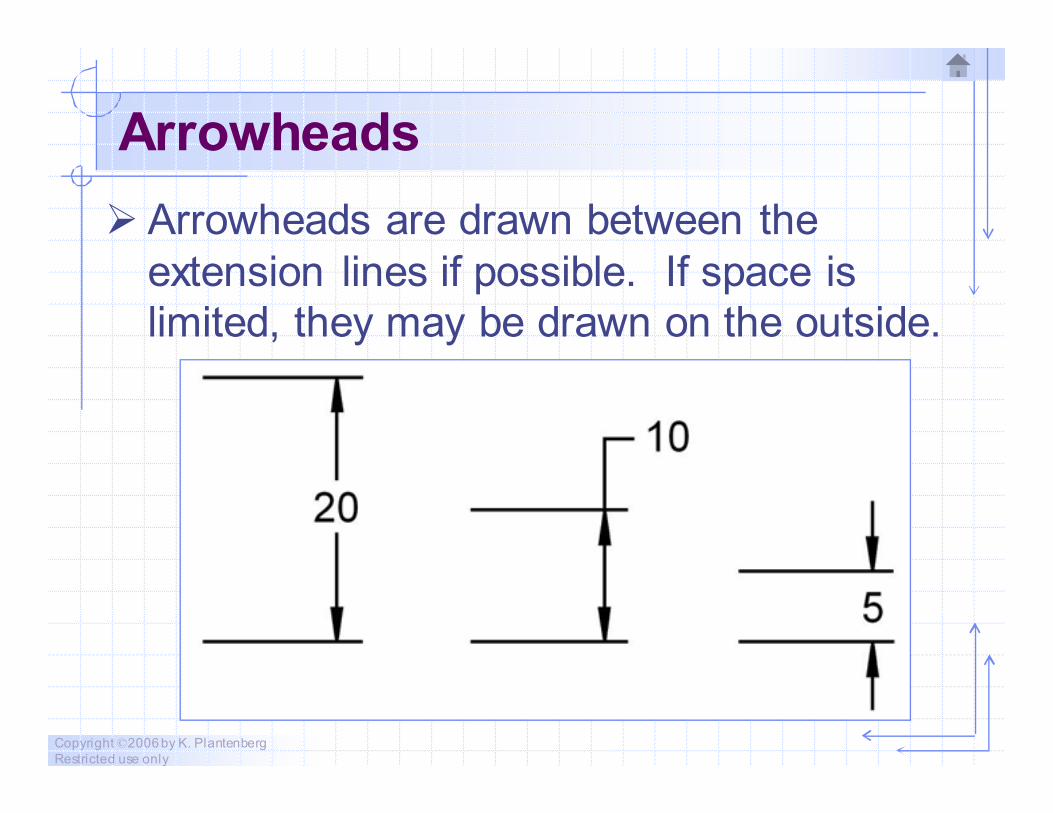
Arrowheads
� Arrowheads are drawn between the
extension lines if possible. If space is
limited, they may be drawn on the outside.
Copyright ©2006 by K. Plantenberg
Restricted use only
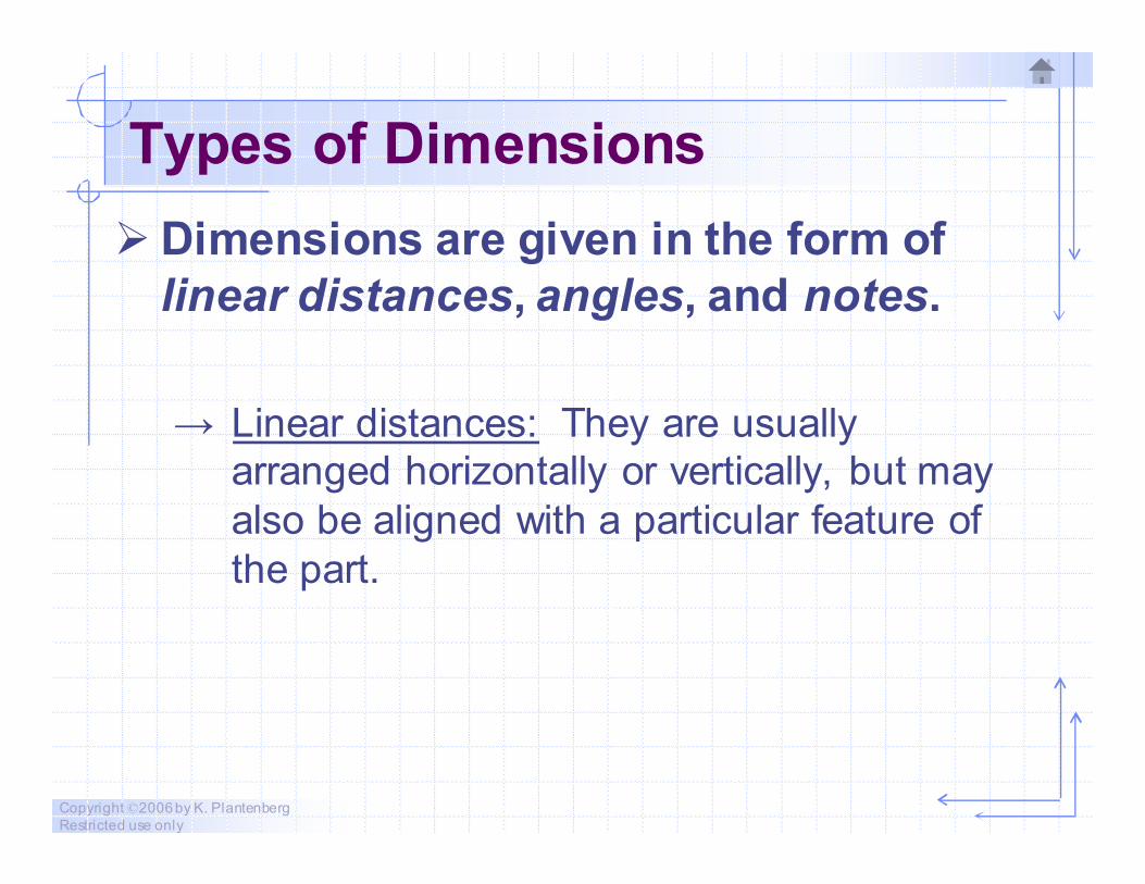
Types of Dimensions
� Dimensions are given in the form of
linear distances, angles, and notes.
→ Linear distances: They are usually
arranged horizontally or vertically, but may
also be aligned with a particular feature of
the part.

Copyright ©2006 by K. Plantenberg
Restricted use only
Types of Dimensions
� Dimensions are given in the form of
linear distances, angles, and notes.
→ Angles: Used to give the angle between
two surfaces or features of a part.
Copyright ©2006 by K. Plantenberg
Restricted use only
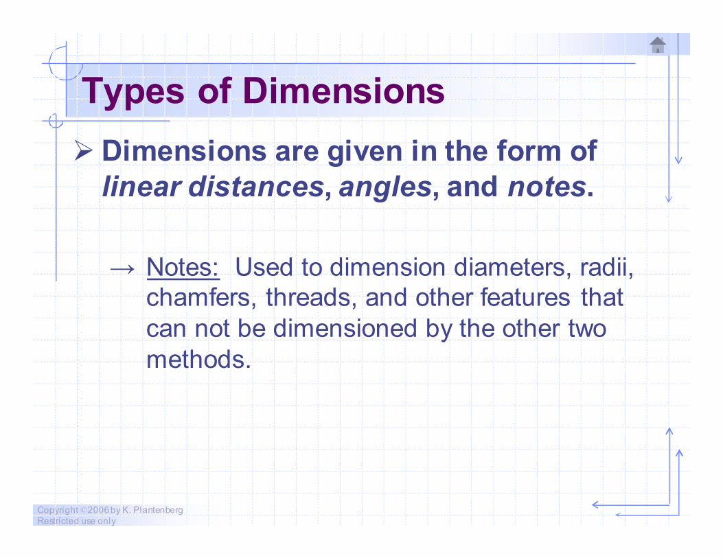
Types of Dimensions
� Dimensions are given in the form of
linear distances, angles, and notes.
→ Notes: Used to dimension diameters, radii,
chamfers, threads, and other features that
can not be dimensioned by the other two
methods.
Copyright ©2006 by K. Plantenberg
Restricted use only
Exercise 2-1
Dimension types

Copyright ©2006 by K. Plantenberg
Restricted use only
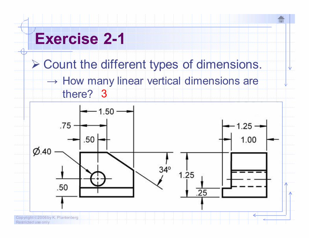
Exercise 2-1
� Count the different types of dimensions.
→ How many linear horizontal dimensions are
there? 5
Copyright ©2006 by K. Plantenberg
Restricted use only
Exercise 2-1
� Count the different types of dimensions.
→ How many linear vertical dimensions are
there? 3
Copyright ©2006 by K. Plantenberg
Restricted use only
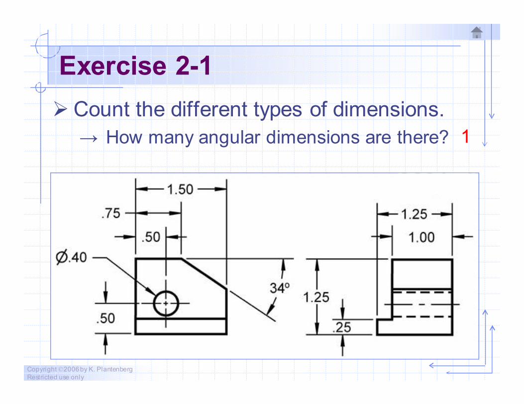
Exercise 2-1
� Count the different types of dimensions.
→ How many angular dimensions are there? 1
Copyright ©2006 by K. Plantenberg
Restricted use only
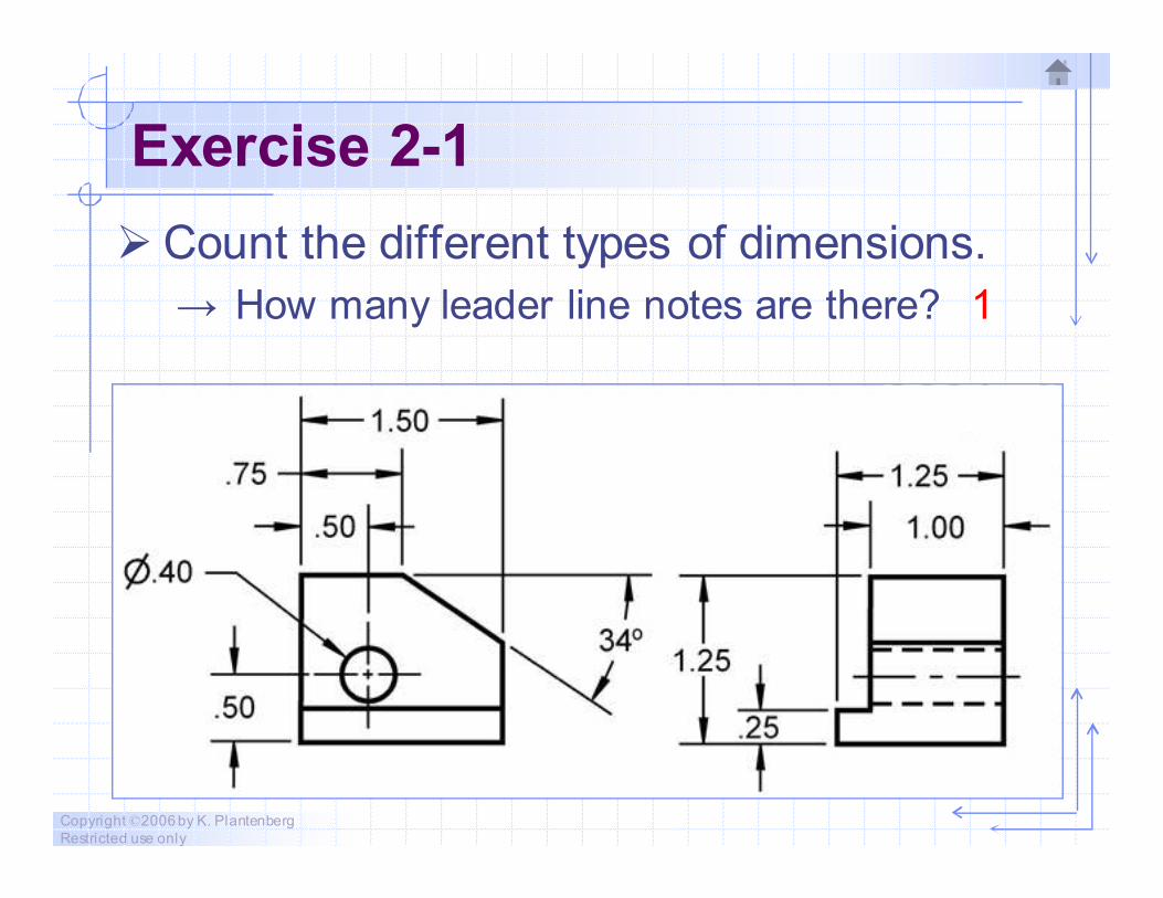
Exercise 2-1
� Count the different types of dimensions.
→ How many leader line notes are there? 1
Copyright ©2006 by K. Plantenberg
Restricted use only
Lettering
� Lettering should be legible, easy to
read, and uniform throughout the
drawing.
→ Upper case letters should be used for all
lettering unless a lower case is required.
→ The minimum lettering height is 0.12 in (3
mm).
Copyright ©2006 by K. Plantenberg
Restricted use only
Dimensioning Symbols
� Dimensioning symbols replace text.
→ The goal of using dimensioning symbols is to
eliminate the need for language translation.
� Why is it important to use symbols.
→ How many products are designed in the
United States?
→ How many products are manufactured or
assembled in the United States?
Copyright ©2006 by K. Plantenberg
Restricted use only
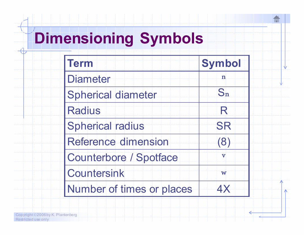
Dimensioning Symbols
Term Symbol
Diameter nnnn
Spherical diameter Snnnn
Radius R
Spherical radius SR
Reference dimension (8)
Counterbore / Spotface vvvv
Countersink wwww
Number of times or places 4X
Copyright ©2006 by K. Plantenberg
Restricted use only
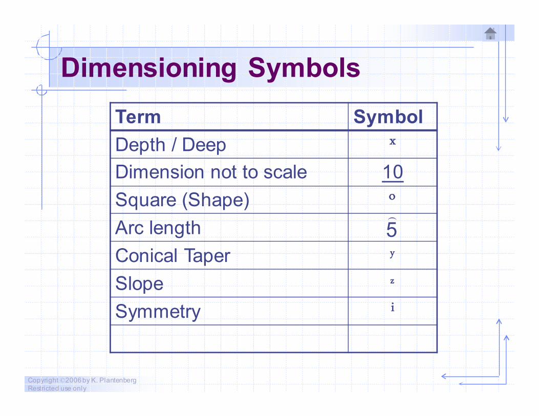
Dimensioning Symbols
Term Symbol
Depth / Deep xxxx
Dimension not to scale 10
Square (Shape) oooo
Arc length
Conical Taper yyyy
Slope zzzz
Symmetry iiii
5)
Copyright ©2006 by K. Plantenberg
Restricted use only
Spacing and Readability
� Dimensions should be easy to read,
and minimize the possibility for
conflicting interpretations.
Copyright ©2006 by K. Plantenberg
Restricted use only
Spacing and Readability
a) The spacing between dimension lines
should be uniform throughout the
drawing.
b) Do not dimension inside an object or
have the dimension line touch the object
unless clearness is gained.
Copyright ©2006 by K. Plantenberg
Restricted use only
Spacing and Readability
c) Dimension text should be horizontal
which means that it is read from the
bottom of the drawing.
d) Dimension text should not cross
dimension, extension or visible lines.
Copyright ©2006 by K. Plantenberg
Restricted use only
Exercise 2-2
Spacing and Readability 1
Copyright ©2006 by K. Plantenberg
Restricted use only
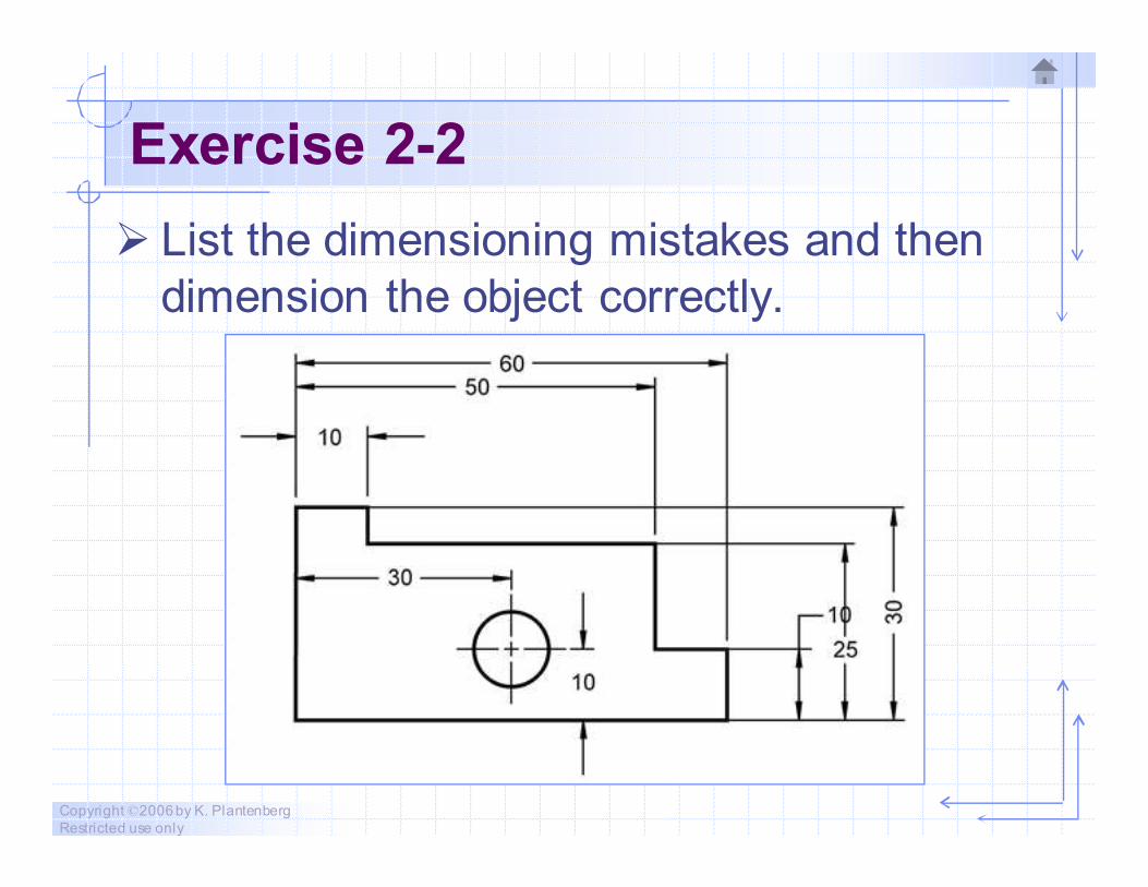
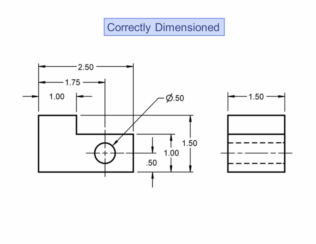
Exercise 2-2
� List the dimensioning mistakes and then
dimension the object correctly.
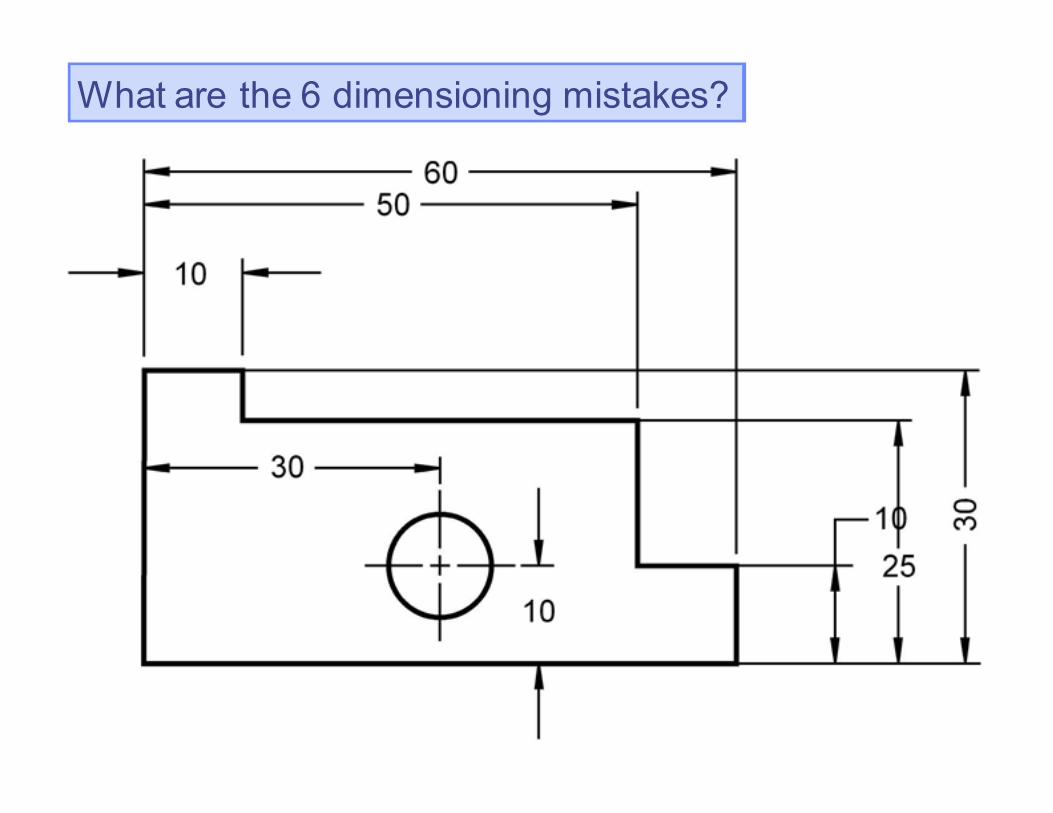
What are the 6 dimensioning mistakes?
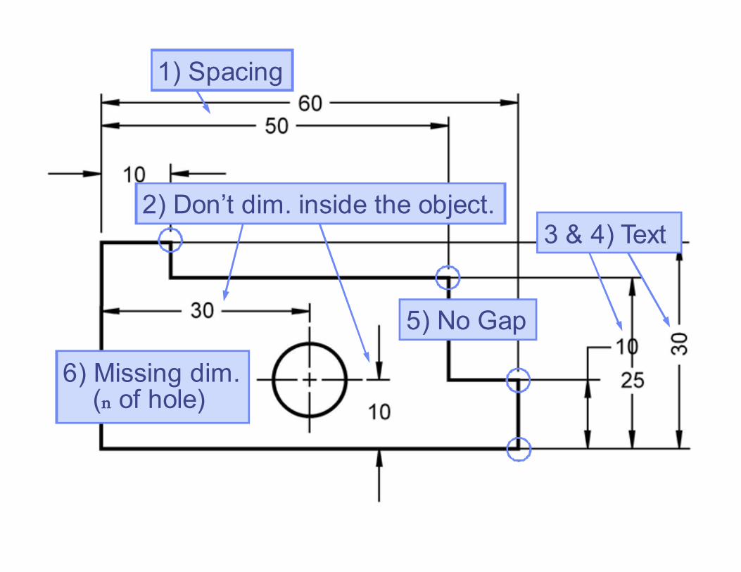
1) Spacing
6) Missing dim. (nnnn of hole)
3 & 4) Text
5) No Gap
2) Don’t dim. inside the object.
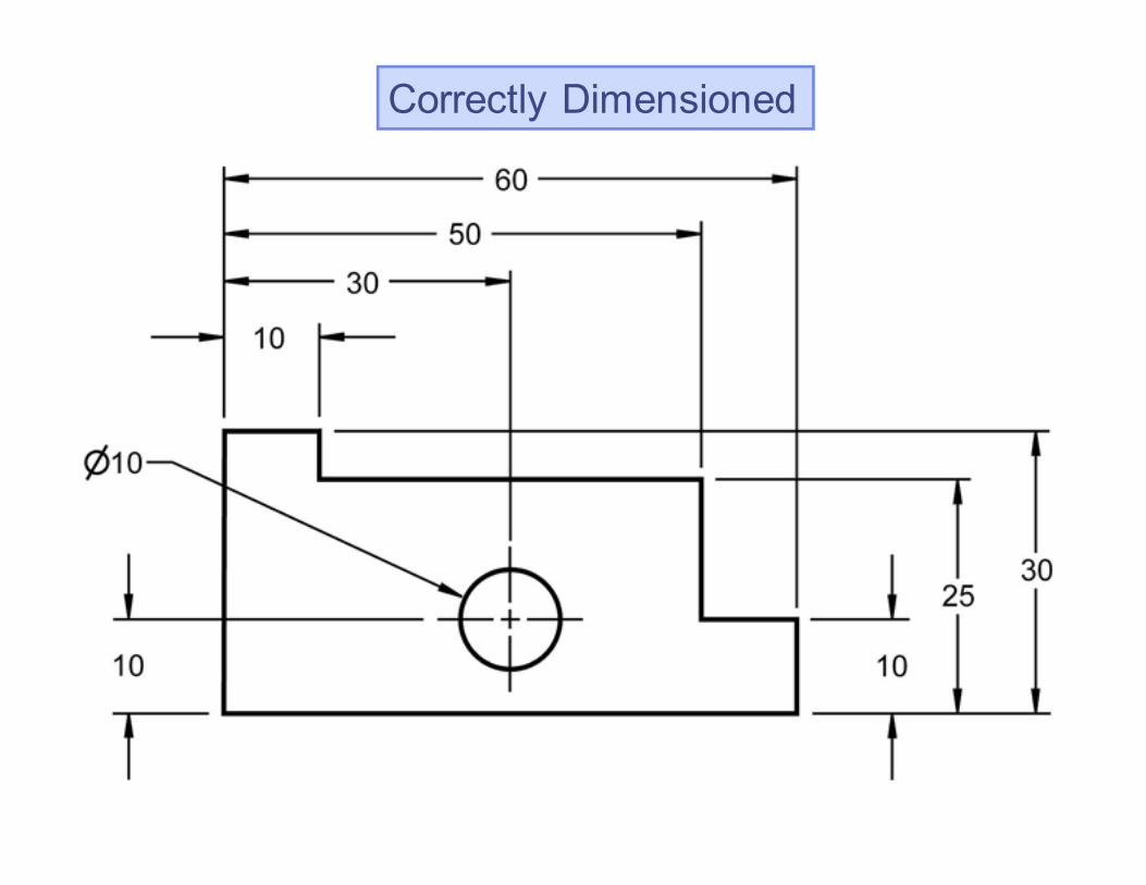
Correctly Dimensioned
Copyright ©2006 by K. Plantenberg
Restricted use only
Spacing and Readability
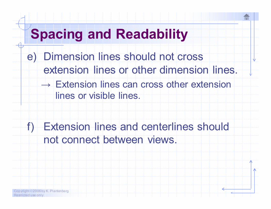
e) Dimension lines should not cross
extension lines or other dimension lines.
→ Extension lines can cross other extension
lines or visible lines.
f) Extension lines and centerlines should
not connect between views.
Copyright ©2006 by K. Plantenberg
Restricted use only
Spacing and Readability
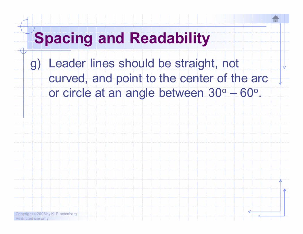
g) Leader lines should be straight, not
curved, and point to the center of the arc
or circle at an angle between 30o – 60o.
Copyright ©2006 by K. Plantenberg
Restricted use only
Exercise 2-3
Spacing and Readability 2
Copyright ©2006 by K. Plantenberg
Restricted use only
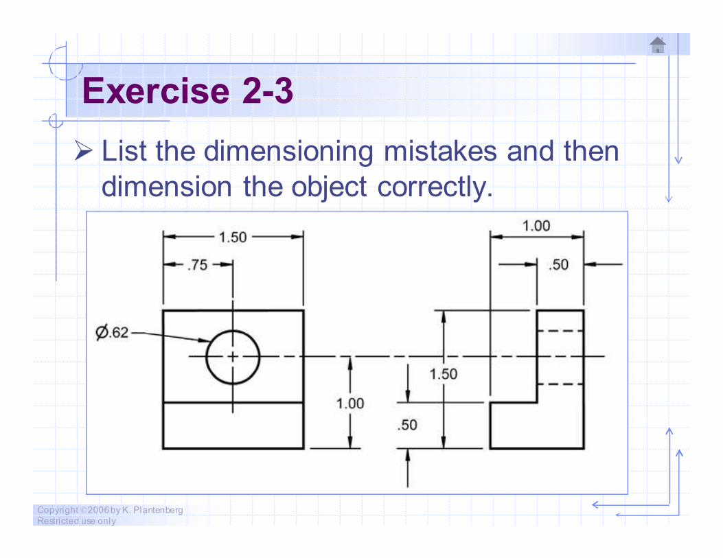
Exercise 2-3
� List the dimensioning mistakes and then
dimension the object correctly.
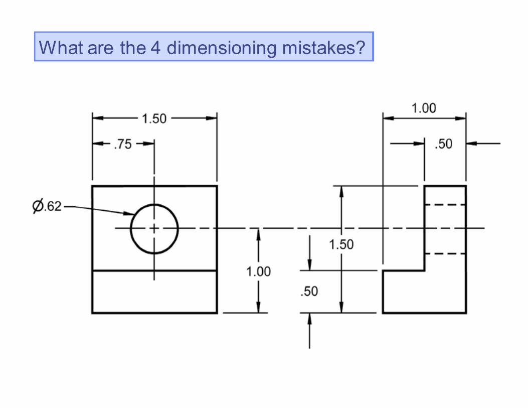
What are the 4 dimensioning mistakes?
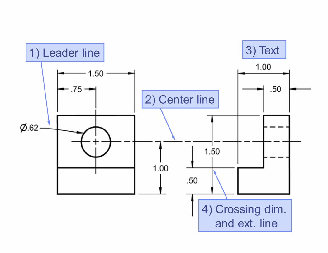
3) Text
2) Center line
4) Crossing dim.
and ext. line
1) Leader line
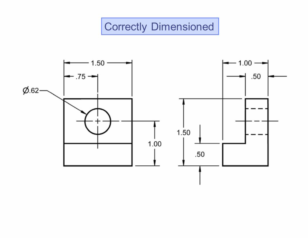
Correctly Dimensioned
Copyright ©2006 by K. Plantenberg
Restricted use only
Spacing and Readability
h) Dimensions should not be duplicated or
the same information given in two
different ways.
→ If a reference dimension is used, the size
value is placed within parentheses (e.g.
(10) ).
Copyright ©2006 by K. Plantenberg
Restricted use only
Exercise 2-4
Duplicate dimensions
Copyright ©2006 by K. Plantenberg
Restricted use only
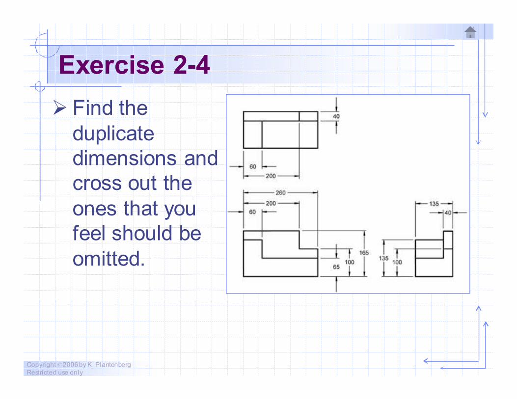
Exercise 2-4
� Find the
duplicate
dimensions and
cross out the
ones that you
feel should be
omitted.
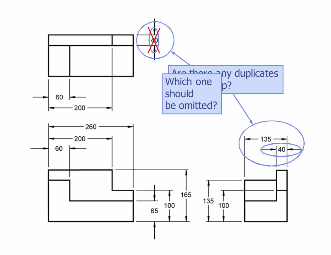
Are there any duplicates
in this group?Which one
shouldbe omitted?
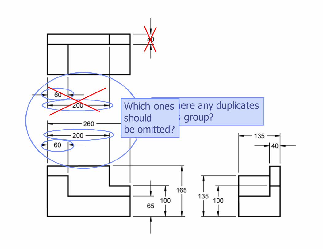
Are there any duplicates
in this group?Which ones
shouldbe omitted?
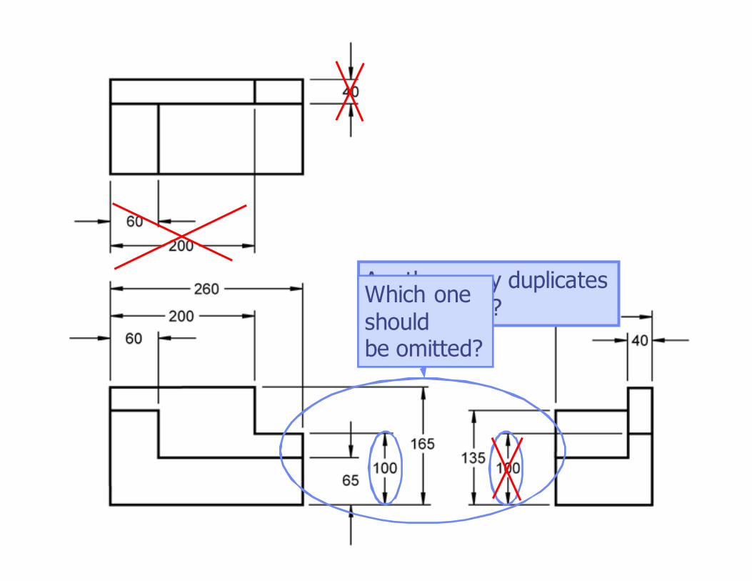
Are there any duplicates
in this group?Which one
shouldbe omitted?
Copyright ©2006 by K. Plantenberg
Restricted use only
Dimension Placement
� Dimensions should be placed in such a
way as to enhance the communication
of your design.
Copyright ©2006 by K. Plantenberg
Restricted use only
Dimension Placement
a) Dimensions should be grouped
whenever possible.
b) Dimensions should be placed between
views, unless clearness is promoted by
placing some outside.
Copyright ©2006 by K. Plantenberg
Restricted use only
Dimension Placement
c) Dimensions should be attached to the
view where the shape is shown best.
d) Do not dimension hidden lines.
Copyright ©2006 by K. Plantenberg
Restricted use only
Exercise 2-5
Dimension placement
Copyright ©2006 by K. Plantenberg
Restricted use only
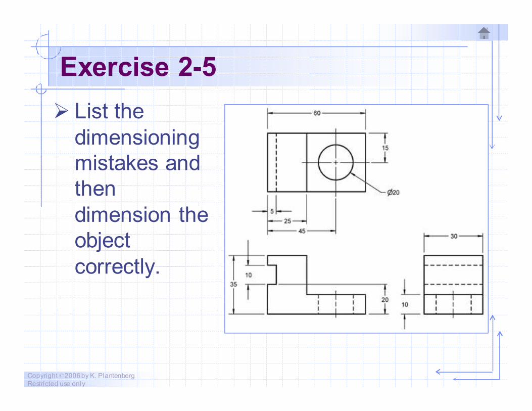
Exercise 2-5
� List the
dimensioning
mistakes and
then
dimension the
object
correctly.
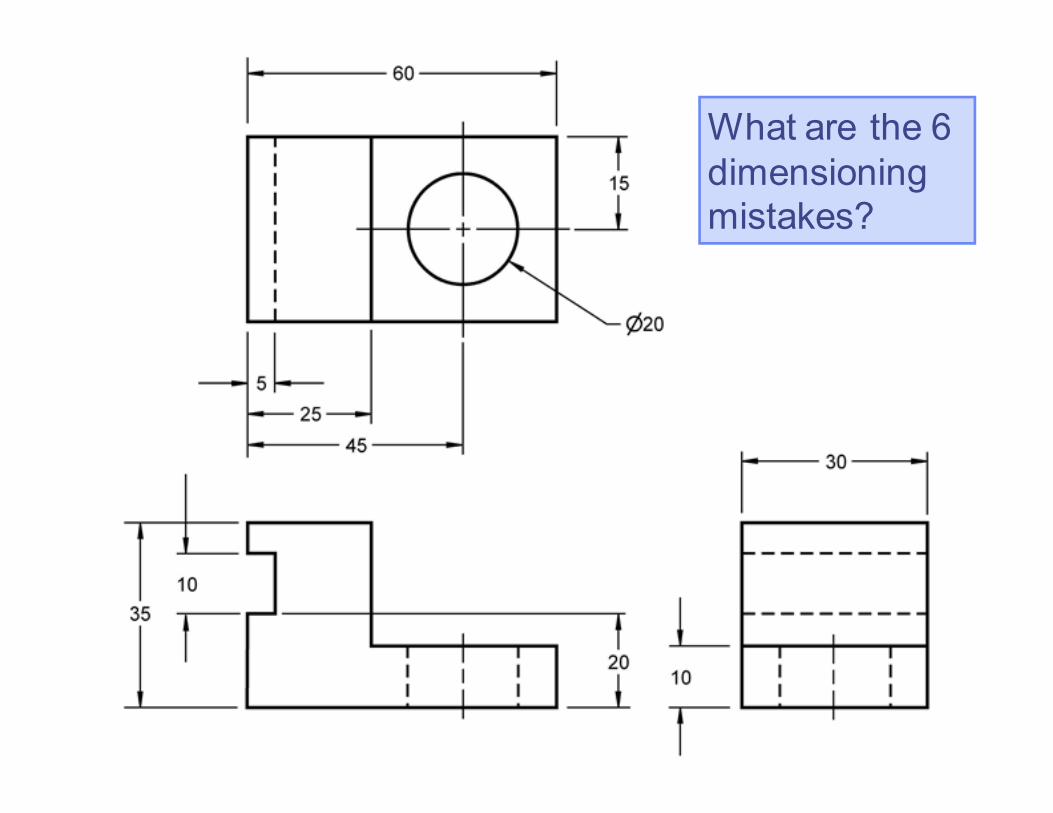
What are the 6
dimensioning
mistakes?
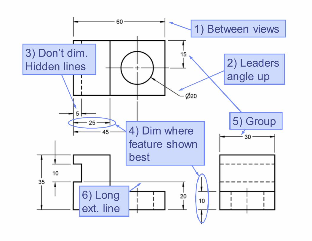
1) Between views
2) Leaders
angle up
3) Don’t dim.
Hidden lines
4) Dim where
feature shown
best
6) Long
ext. line
5) Group
Correctly Dimensioned
Copyright ©2006 by K. Plantenberg
Restricted use only
Dimensioning
2-4) Dimensioning and
Locating Simple Features
Copyright ©2006 by K. Plantenberg
Restricted use only
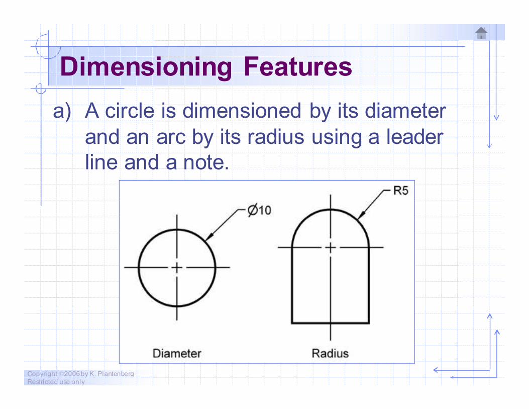
Dimensioning Features
a) A circle is dimensioned by its diameter
and an arc by its radius using a leader
line and a note.
Copyright ©2006 by K. Plantenberg
Restricted use only
Exercise 2-6
Circular and rectangular views
Copyright ©2006 by K. Plantenberg
Restricted use only
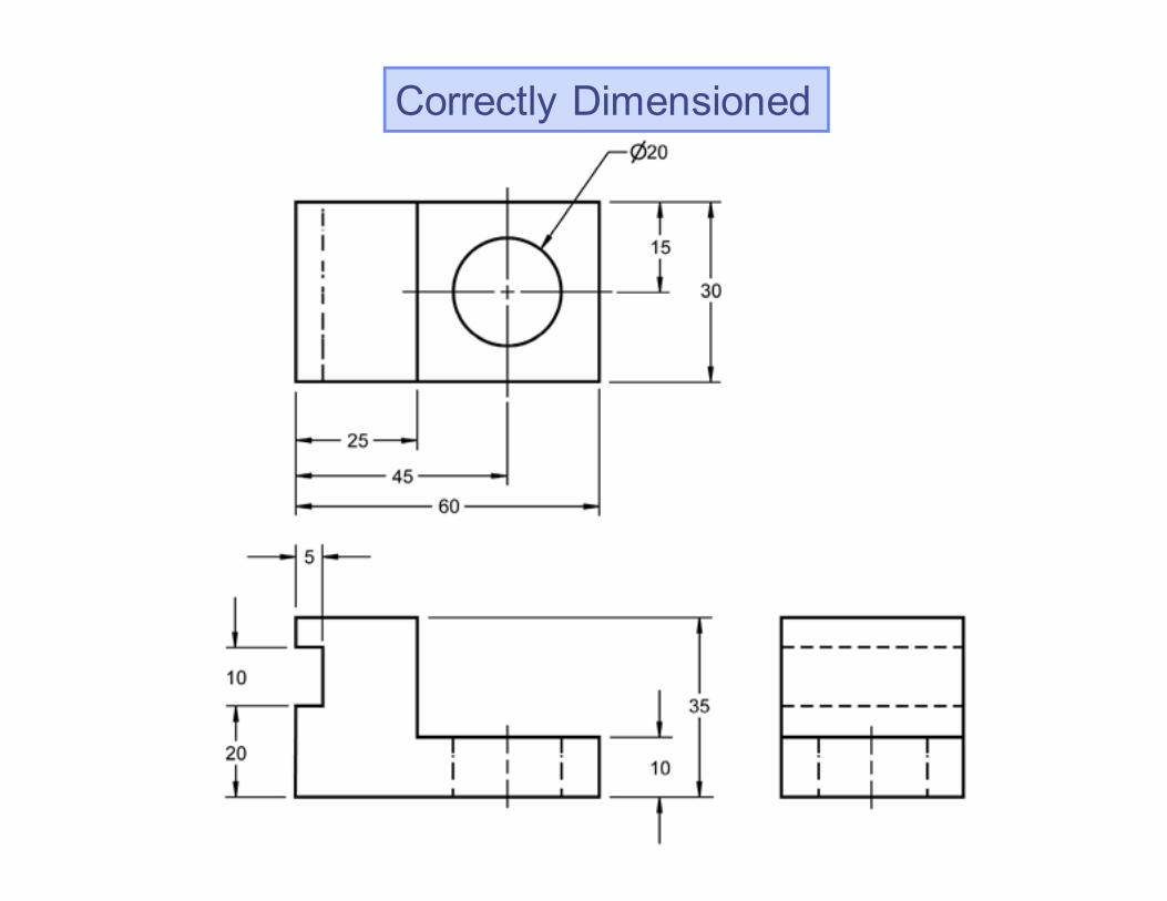
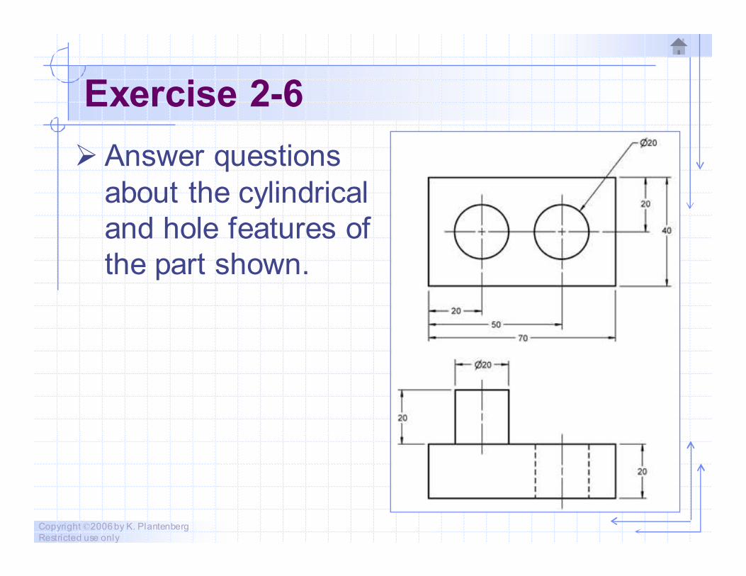
Exercise 2-6
� Answer questions
about the cylindrical
and hole features of
the part shown.
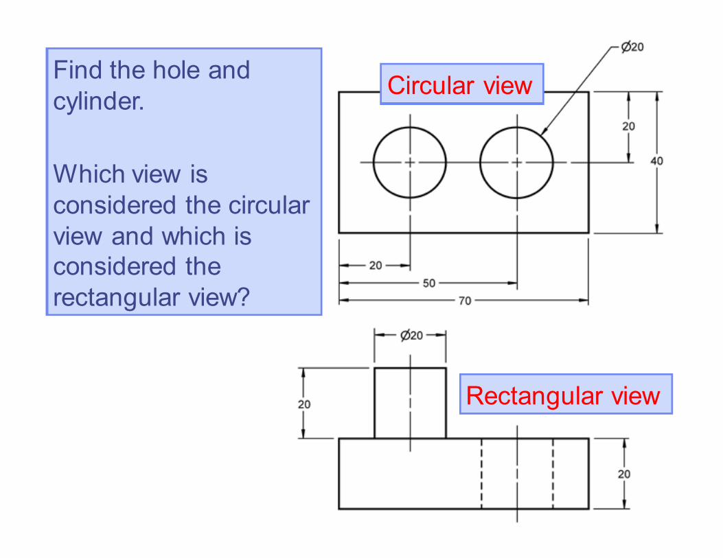
Find the hole and
cylinder.
Which view is
considered the circular
view and which is
considered the
rectangular view?
Circular view
Rectangular view
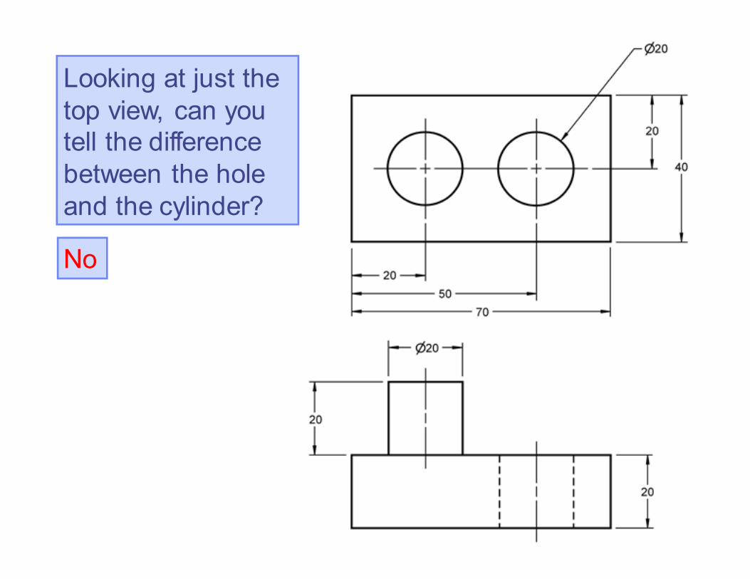
Looking at just the
top view, can you
tell the difference
between the hole
and the cylinder?
No
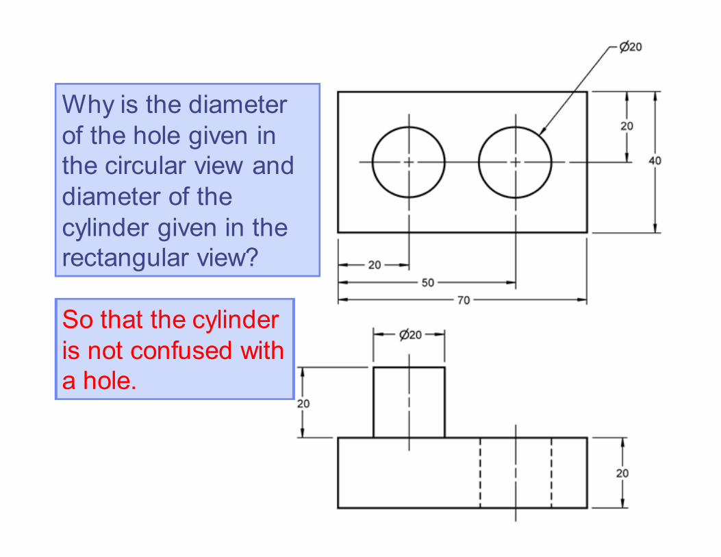
So that the cylinder
is not confused with
a hole.
Why is the diameter
of the hole given in
the circular view and
diameter of the
cylinder given in the
rectangular view?
Copyright ©2006 by K. Plantenberg
Restricted use only
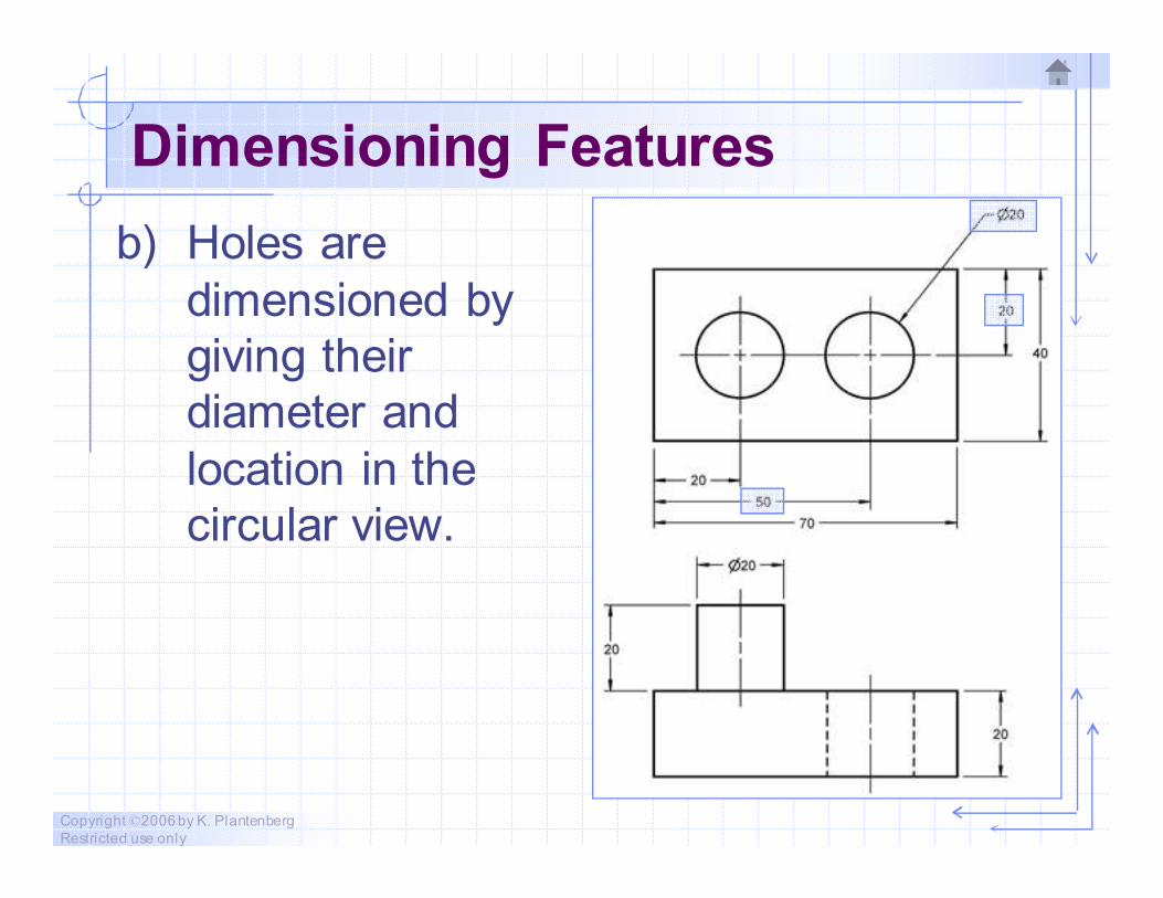
Dimensioning Features
b) Holes are
dimensioned by
giving their
diameter and
location in the
circular view.

Copyright ©2006 by K. Plantenberg
Restricted use only
Dimensioning Features
c) A cylinder is
dimensioned by
giving its diameter
and length in the
rectangular view,
and is located in
the circular view.
Copyright ©2006 by K. Plantenberg
Restricted use only
Dimensioning Features
d) Repetitive features or dimensions may
be specified by using the symbol “X”
along with the number of times the
feature is repeated.
→ There is no space between the number of
times the feature is repeated and the “X”
symbol, however, there is a space between
the symbol “X” and the dimension.
Copyright ©2006 by K. Plantenberg
Restricted use only
Exercise 2-7
Dimensioning and locating
features
Copyright ©2006 by K. Plantenberg
Restricted use only
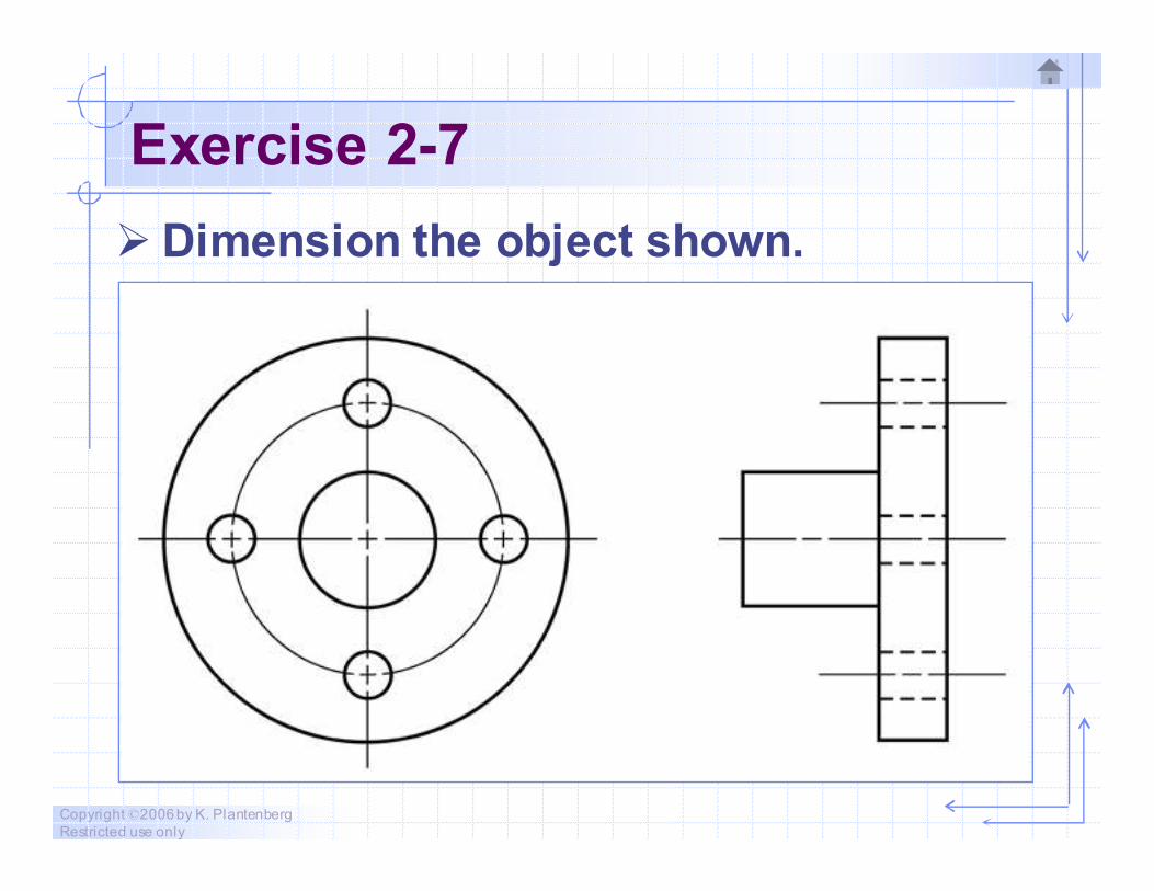
Exercise 2-7
� Dimension the object shown.
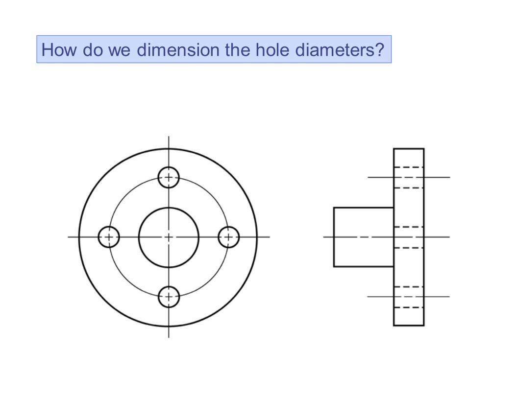
How do we dimension the hole diameters?
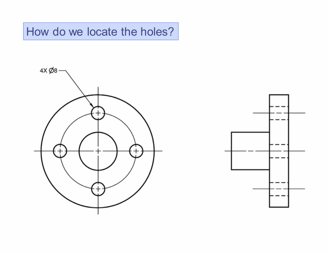
How do we locate the holes?
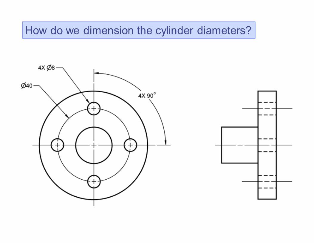
How do we dimension the cylinder diameters?
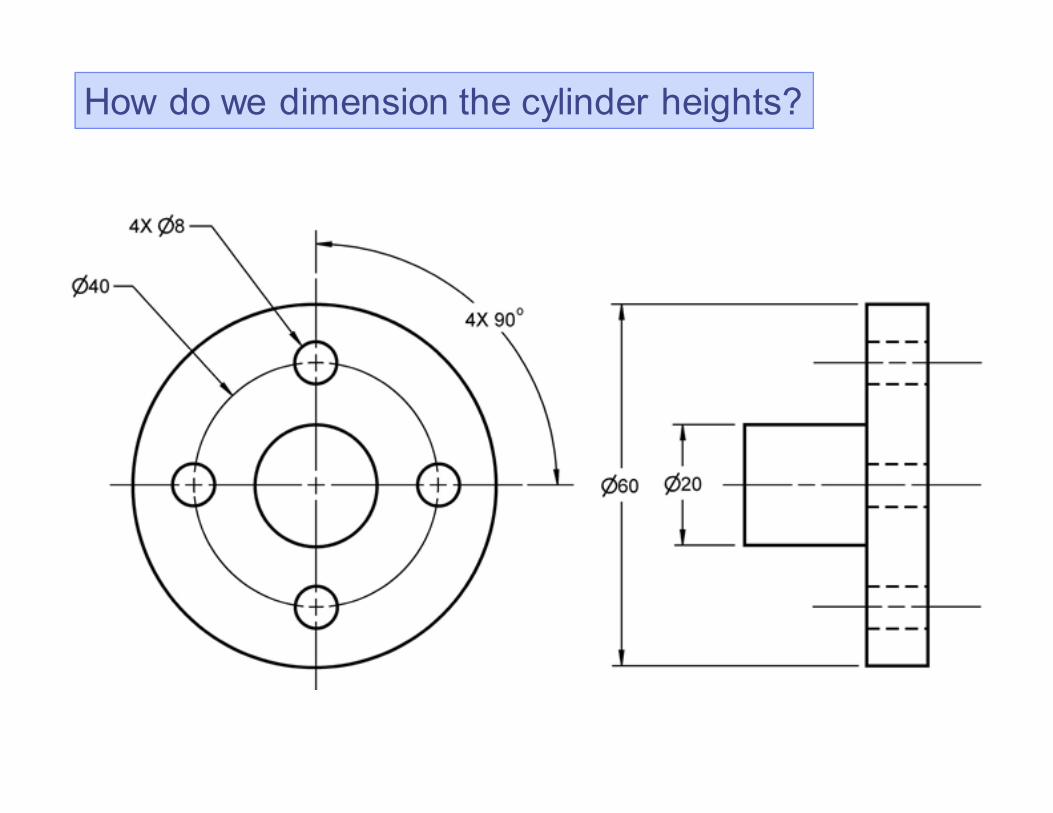
How do we dimension the cylinder heights?
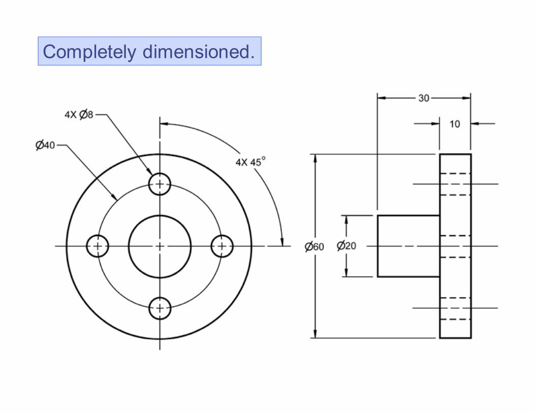
Completely dimensioned.
Copyright ©2006 by K. Plantenberg
Restricted use only
Dimensioning
2-5) Dimensioning and
Locating Advanced Features
Skip advanced topic
Copyright ©2006 by K. Plantenberg
Restricted use only
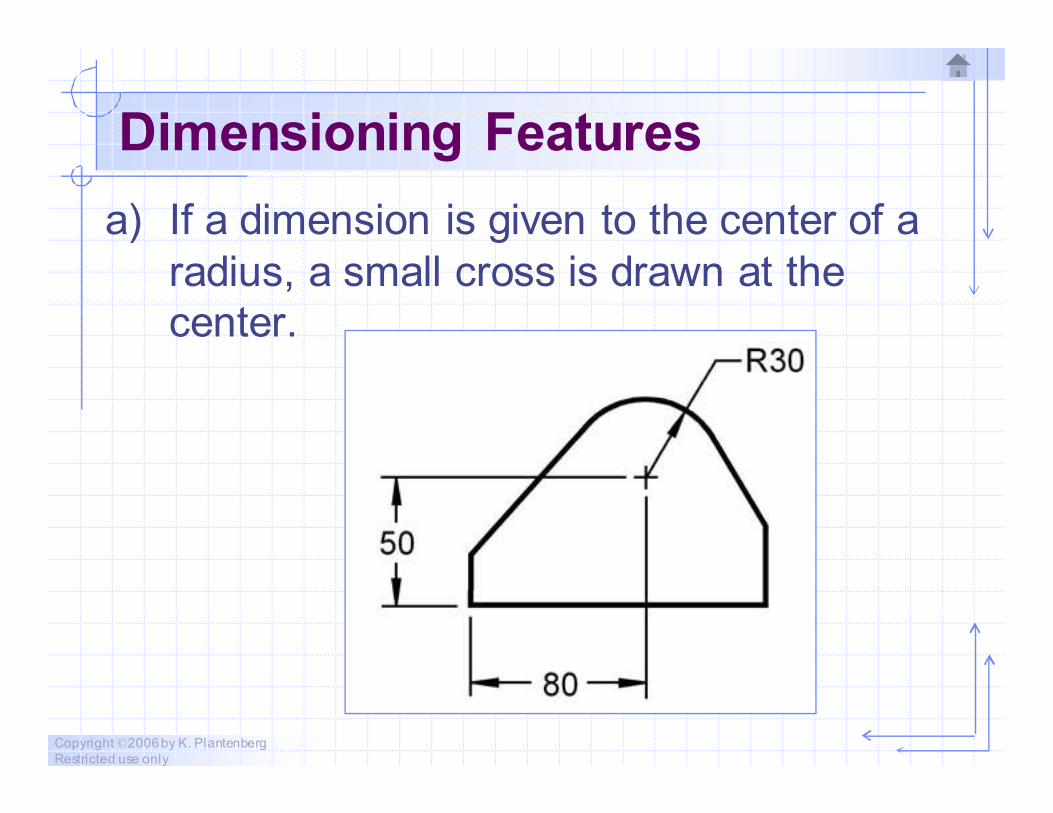
Dimensioning Features
a) If a dimension is given to the center of a
radius, a small cross is drawn at the
center.
Copyright ©2006 by K. Plantenberg
Restricted use only
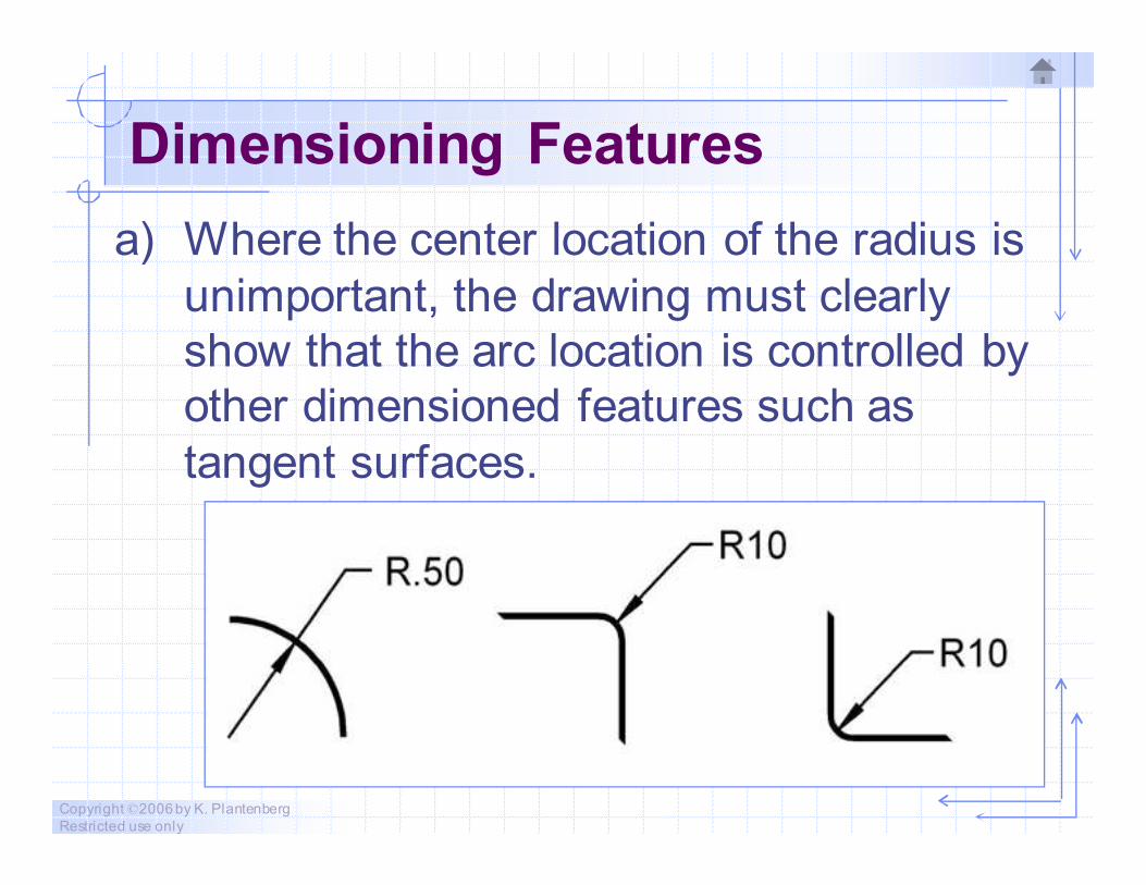
Dimensioning Features
a) Where the center location of the radius is
unimportant, the drawing must clearly
show that the arc location is controlled by
other dimensioned features such as
tangent surfaces.
Copyright ©2006 by K. Plantenberg
Restricted use only
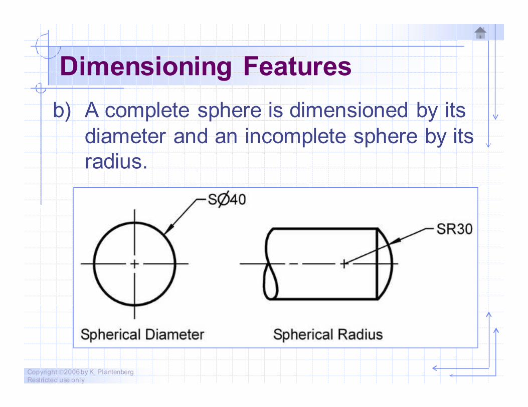
Dimensioning Features
b) A complete sphere is dimensioned by its
diameter and an incomplete sphere by its
radius.
Copyright ©2006 by K. Plantenberg
Restricted use only
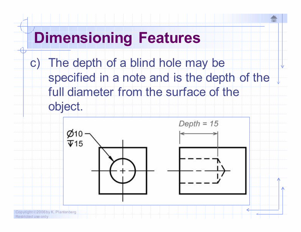
Dimensioning Features
c) The depth of a blind hole may be
specified in a note and is the depth of the
full diameter from the surface of the
object.
Copyright ©2006 by K. Plantenberg
Restricted use only
Dimensioning Features
d) If a hole goes completely through the
feature and it is not clearly shown on the
drawing, the abbreviation “THRU” follows
the dimension.
Copyright ©2006 by K. Plantenberg
Restricted use only
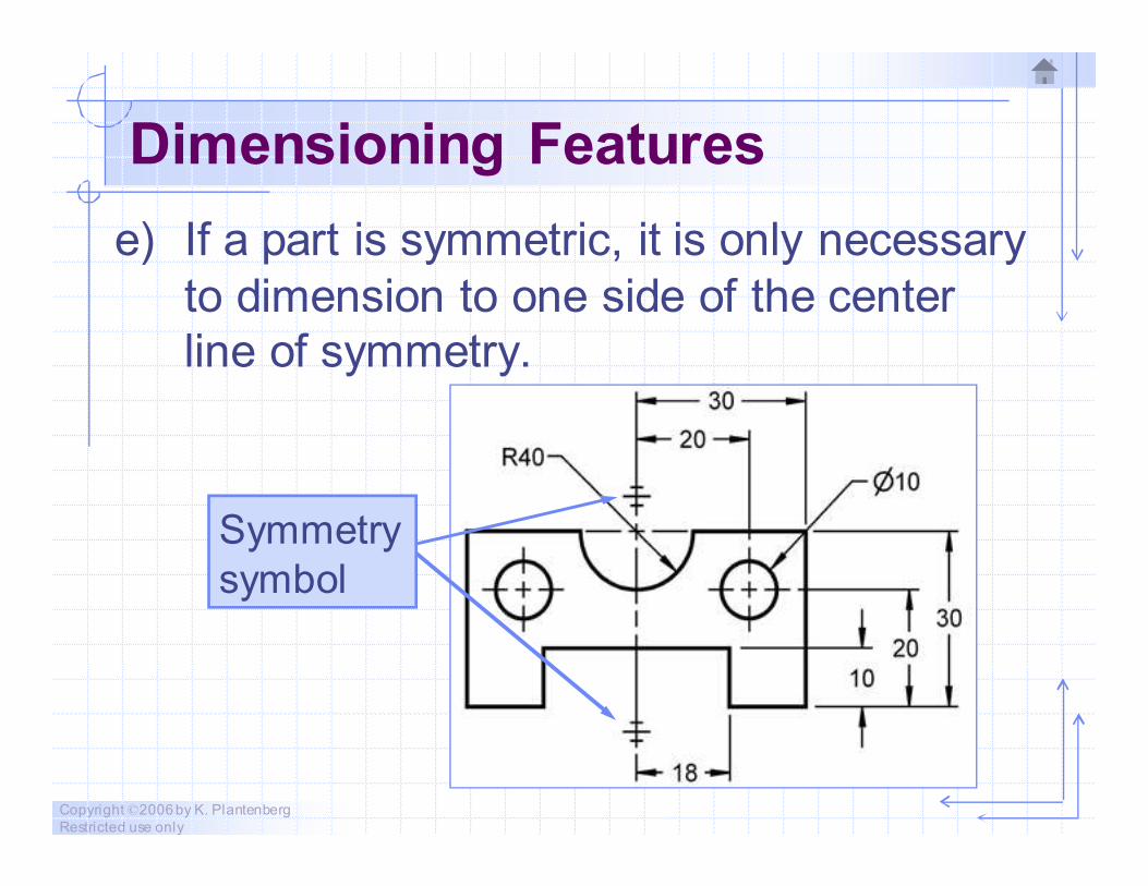
Dimensioning Features
e) If a part is symmetric, it is only necessary
to dimension to one side of the center
line of symmetry.
Symmetry
symbol
Copyright ©2006 by K. Plantenberg
Restricted use only
Dimensioning Features
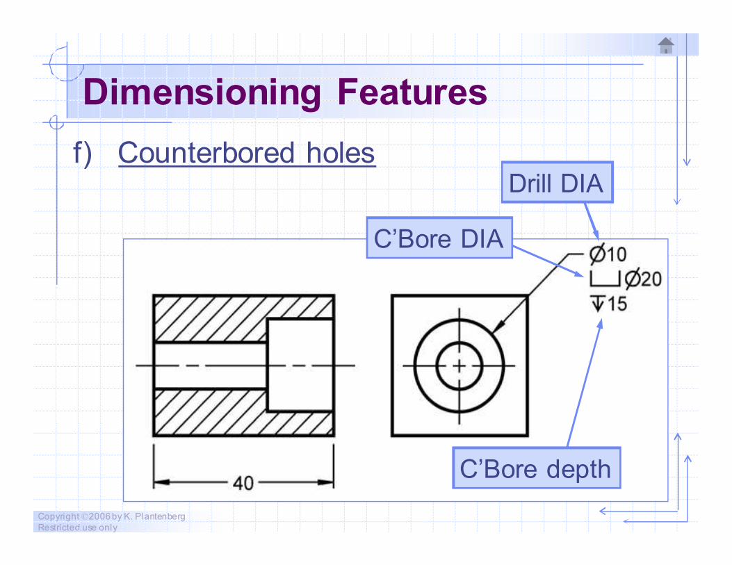
f) Counterbored holesDrill DIA
C’Bore DIA
C’Bore depth
Copyright ©2006 by K. Plantenberg
Restricted use only
Dimensioning Features
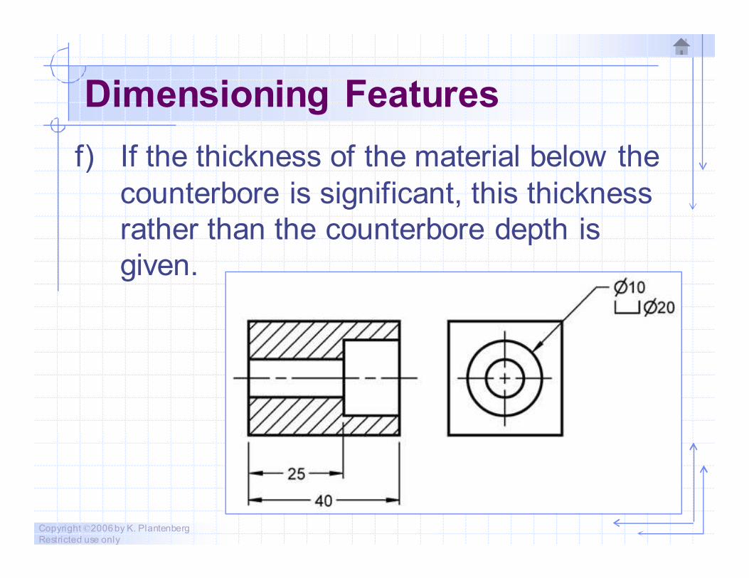
f) If the thickness of the material below the
counterbore is significant, this thickness
rather than the counterbore depth is
given.
Copyright ©2006 by K. Plantenberg
Restricted use only
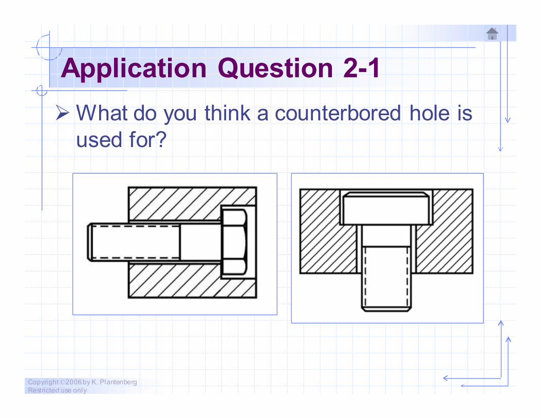
Application Question 2-1
� What do you think a counterbored hole is
used for?
Copyright ©2006 by K. Plantenberg
Restricted use only
Dimensioning Features
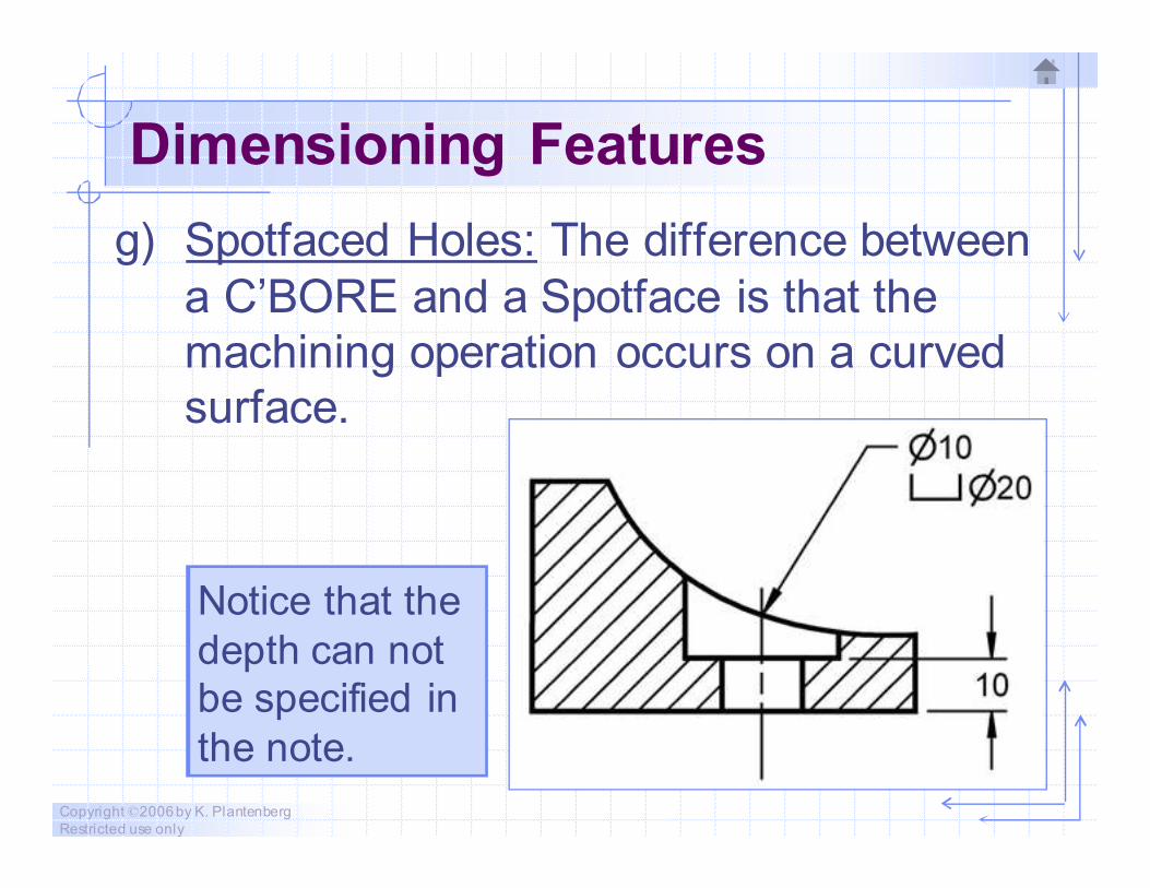
g) Spotfaced Holes: The difference between
a C’BORE and a Spotface is that the
machining operation occurs on a curved
surface.
Notice that the
depth can not
be specified in
the note.
Copyright ©2006 by K. Plantenberg
Restricted use only
Dimensioning Features
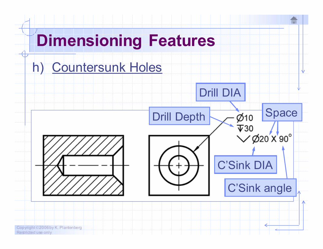
h) Countersunk Holes
Drill DIA
Drill Depth
C’Sink DIA
C’Sink angle
Space
Copyright ©2006 by K. Plantenberg
Restricted use only
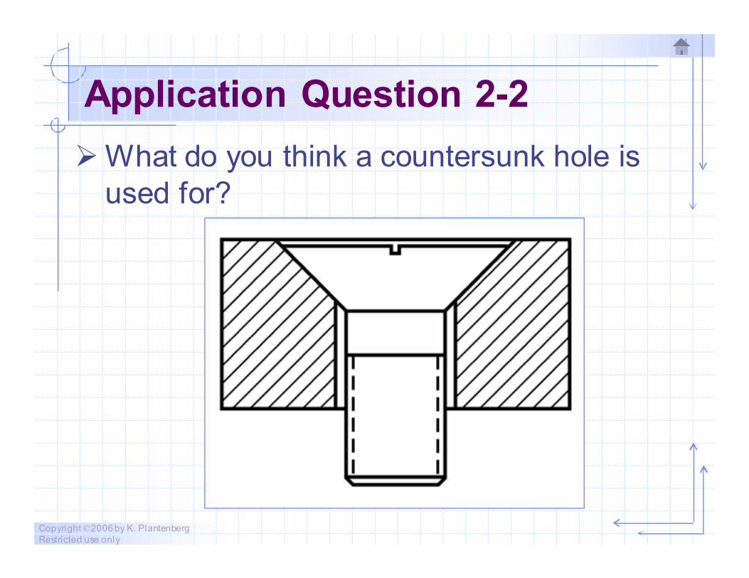
Application Question 2-2
� What do you think a countersunk hole is
used for?
Copyright ©2006 by K. Plantenberg
Restricted use only
Dimensioning Features
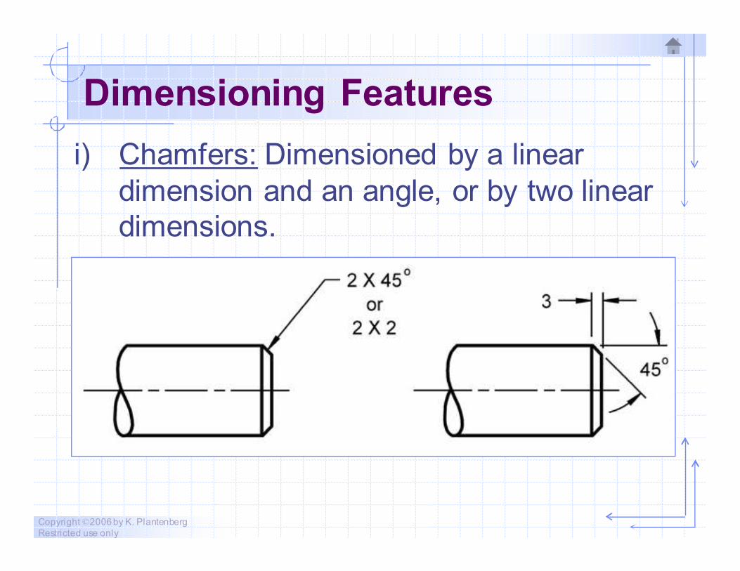
i) Chamfers: Dimensioned by a linear
dimension and an angle, or by two linear
dimensions.
Copyright ©2006 by K. Plantenberg
Restricted use only
Dimensioning Features
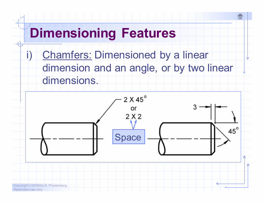
i) Chamfers: Dimensioned by a linear
dimension and an angle, or by two linear
dimensions.
Space
Copyright ©2006 by K. Plantenberg
Restricted use only
Application Question 2-3
� What do you think a chamfer is used for?
Safety.
Improve engagement of mating parts.
Copyright ©2006 by K. Plantenberg
Restricted use only
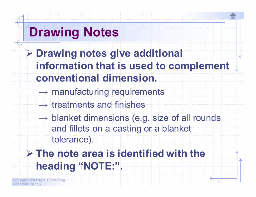
Drawing Notes
� Drawing notes give additional
information that is used to complement
conventional dimension.
→ manufacturing requirements
→ treatments and finishes
→ blanket dimensions (e.g. size of all rounds
and fillets on a casting or a blanket
tolerance).
� The note area is identified with the
heading “NOTE:”.
Copyright ©2006 by K. Plantenberg
Restricted use only
Exercise 2-8
Advanced features
Copyright ©2006 by K. Plantenberg
Restricted use only
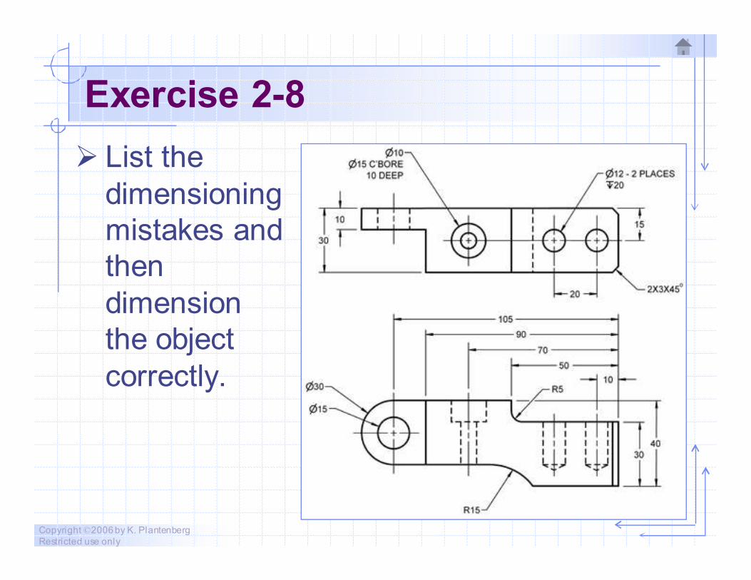
Exercise 2-8
� List the
dimensioning
mistakes and
then
dimension
the object
correctly.
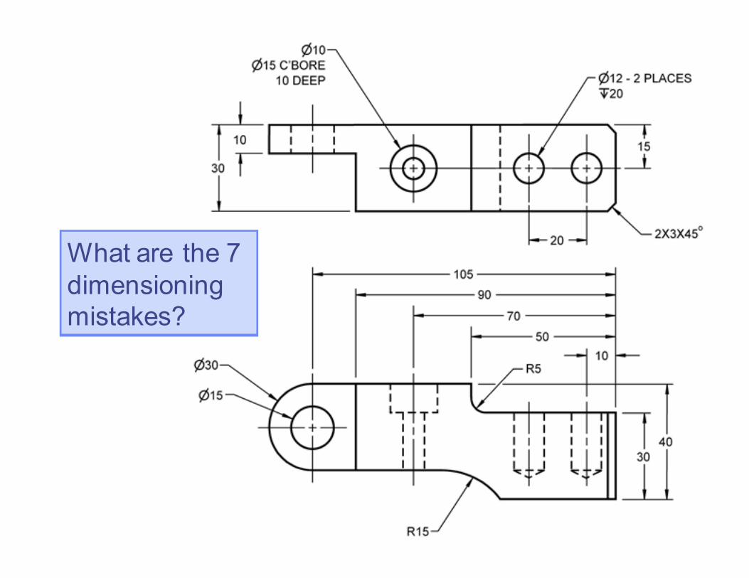
What are the 7
dimensioning
mistakes?
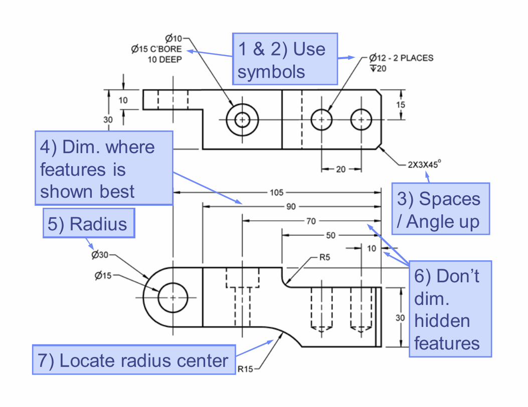
1 & 2) Use
symbols
3) Spaces
/ Angle up5) Radius
7) Locate radius center
6) Don’t
dim.
hidden
features
4) Dim. where
features is
shown best
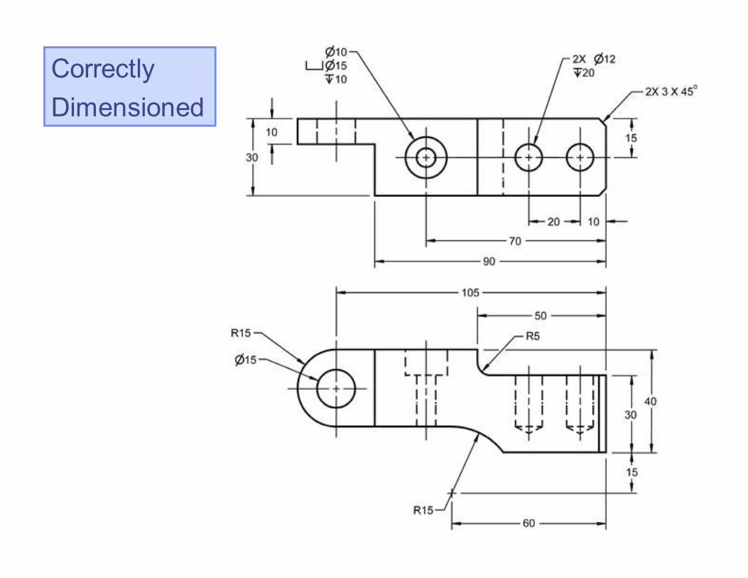
Correctly
Dimensioned

Copyright ©2006 by K. Plantenberg
Restricted use only
Dimensioning
2-6) Dimension Choice
Copyright ©2006 by K. Plantenberg
Restricted use only
Dimension Choice
� Dimension placement and dimension
text influences the manufacturing
process used to make the part.
→ Manufacturing process should not be
specifically stated on the drawing.
� Choose dimensions based on function
first then manufacturing.
Copyright ©2006 by K. Plantenberg
Restricted use only
Units and Decimal Places
a) Decimal dimensions should be used for
all machining dimensions.
→ You may encounter a drawing that specifies
standard drills, broaches, and the like by
size.
→ For drill sizes that are given by number or
letter, a decimal size should also be given.
Copyright ©2006 by K. Plantenberg
Restricted use only
Units and Decimal Places
b) Metric dimensions are given in ‘mm’ and
to 0 or 1 decimal place (e.g. 10, 10.2).
→ When the dimension is less than a
millimeter, a zero should proceed the
decimal point (e.g. 0.5).
Copyright ©2006 by K. Plantenberg
Restricted use only
Units and Decimal Places
c) English dimensions are given in ‘inches’
and to 2 decimal places (e.g. 1.25).
→ A zero is not shown before the decimal
point for values less than one inch (e.g.
.75).
Copyright ©2006 by K. Plantenberg
Restricted use only
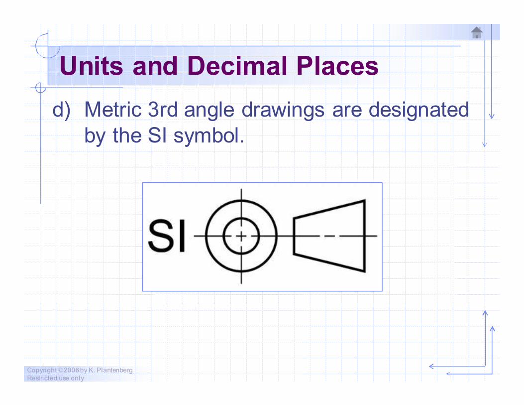
Units and Decimal Places
d) Metric 3rd angle drawings are designated
by the SI symbol.

Copyright ©2006 by K. Plantenberg
Restricted use only
Locating Features Using Datums
� Consider three mutually perpendicular
datum planes.
→ These planes are imaginary and
theoretically exact.
Copyright ©2006 by K. Plantenberg
Restricted use only
Locating Features Using Datums
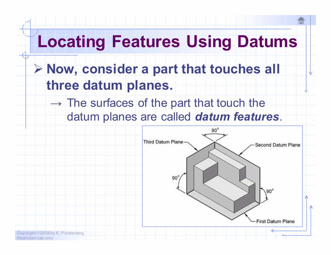
� Now, consider a part that touches all
three datum planes.
→ The surfaces of the part that touch the
datum planes are called datum features.
Copyright ©2006 by K. Plantenberg
Restricted use only
Locating Features Using Datums
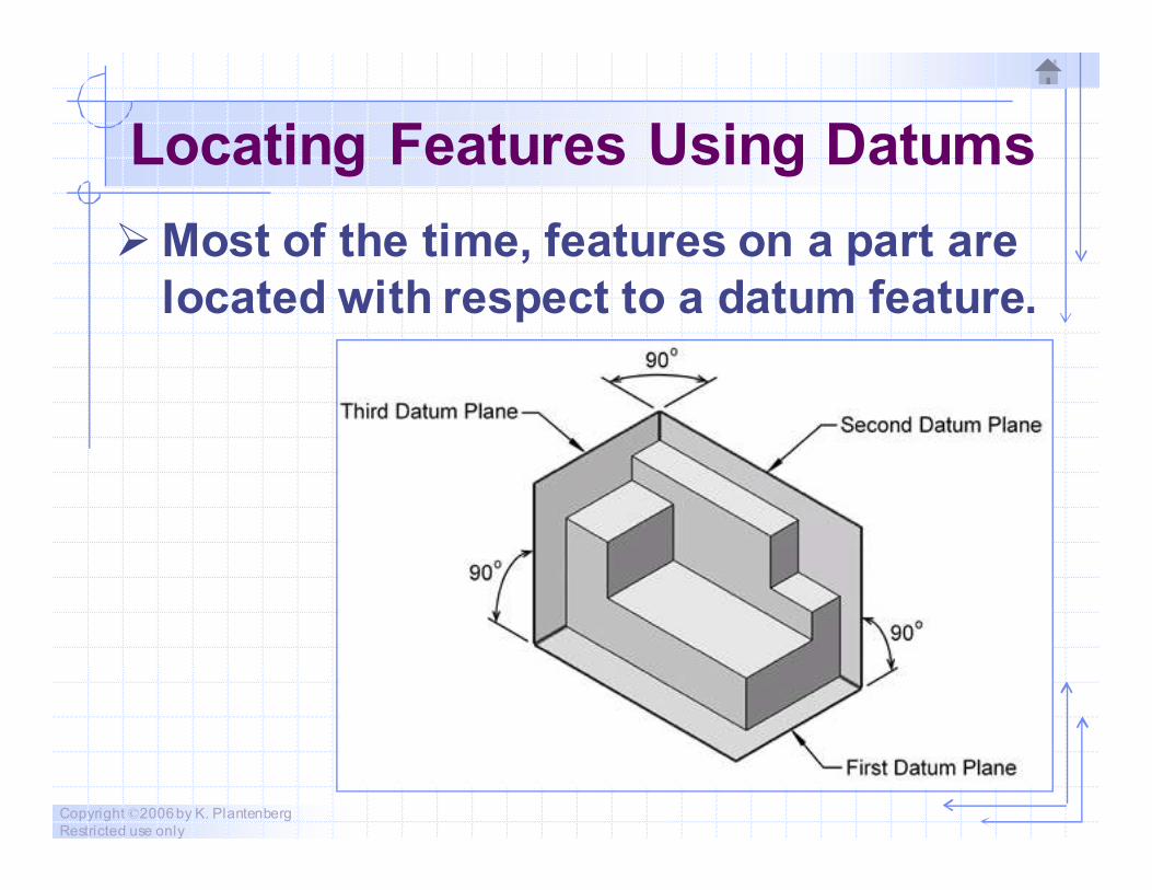
� Most of the time, features on a part are
located with respect to a datum feature.

Copyright ©2006 by K. Plantenberg
Restricted use only
Locating Features Using Datums
Copyright ©2006 by K. Plantenberg
Restricted use only
Locating Features Using Datums
� How do we choose which surface will
be a datum feature?
� Good datum features are:
→ functionally important surfaces
→ mating surfaces
→ big enough to permit its use in
manufacturing the part
Copyright ©2006 by K. Plantenberg
Restricted use only
Locating Features Using Datums
� In a class setting, do we always know
the function of the part?
� We need to make an educated guess as
to the function of the part.
Copyright ©2006 by K. Plantenberg
Restricted use only
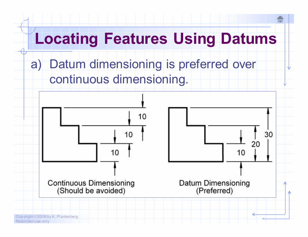
Locating Features Using Datums
a) Datum dimensioning is preferred over
continuous dimensioning.
Copyright ©2006 by K. Plantenberg
Restricted use only
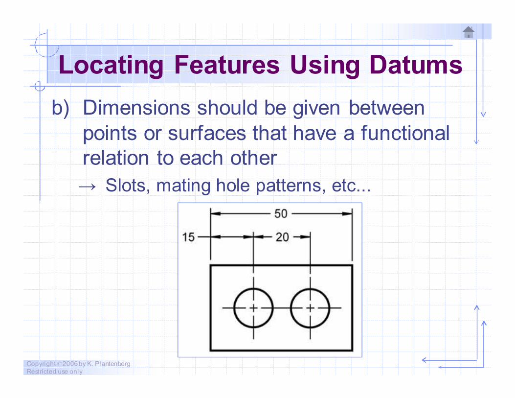
Locating Features Using Datums
b) Dimensions should be given between
points or surfaces that have a functional
relation to each other
→ Slots, mating hole patterns, etc...
Copyright ©2006 by K. Plantenberg
Restricted use only
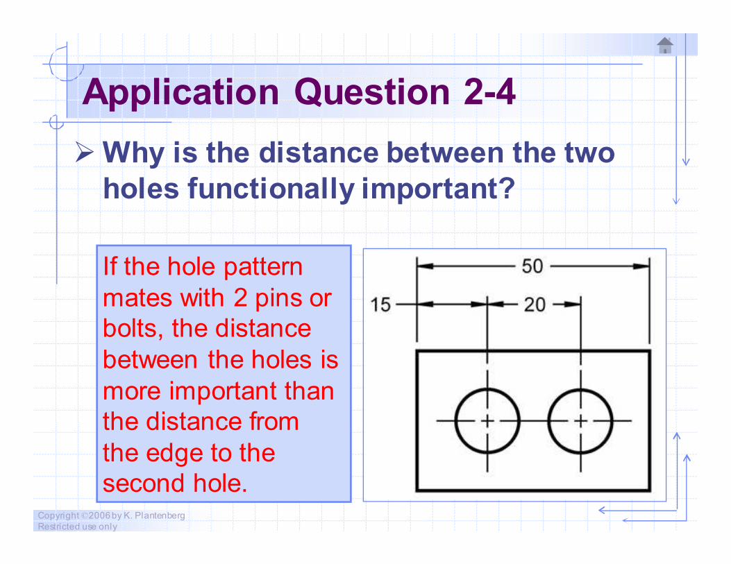
Application Question 2-4
� Why is the distance between the two
holes functionally important?
If the hole pattern
mates with 2 pins or
bolts, the distance
between the holes is
more important than
the distance from
the edge to the
second hole.
Copyright ©2006 by K. Plantenberg
Restricted use only
Dimension Accuracy
� There is no such thing as an "exact"
measurement.
→ Every dimension has an implied or stated
tolerance associated with it.
→ A tolerance is the amount a dimension is
allowed to vary.
Copyright ©2006 by K. Plantenberg
Restricted use only
Exercise 2-9
Dimension Accuracy
Copyright ©2006 by K. Plantenberg
Restricted use only
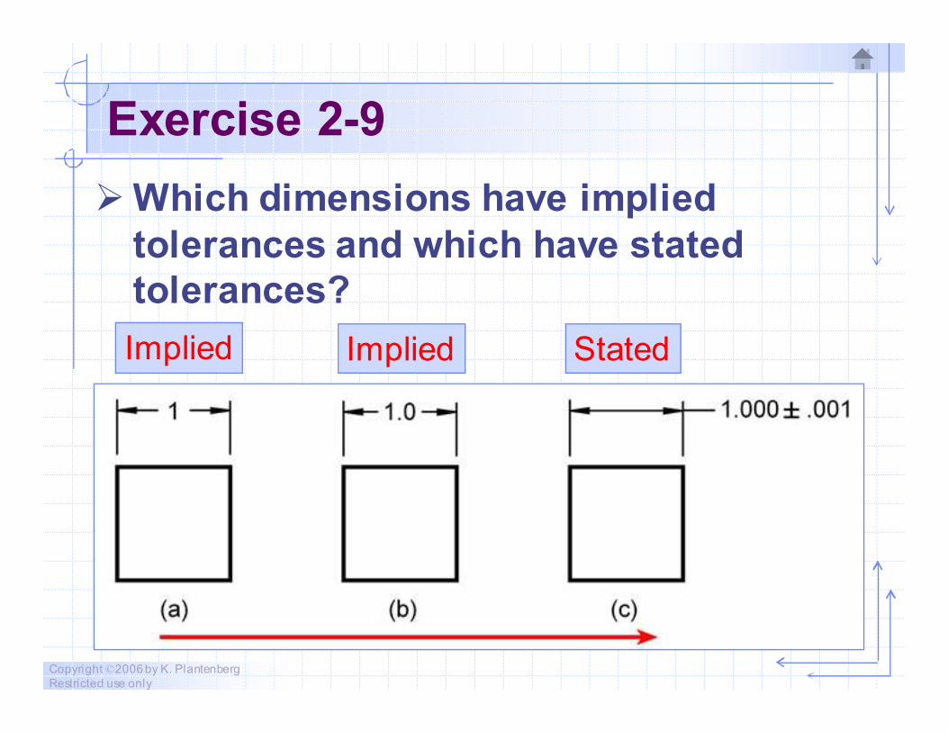
Exercise 2-9
� Which dimensions have implied
tolerances and which have stated
tolerances?
Implied StatedImplied
Copyright ©2006 by K. Plantenberg
Restricted use only
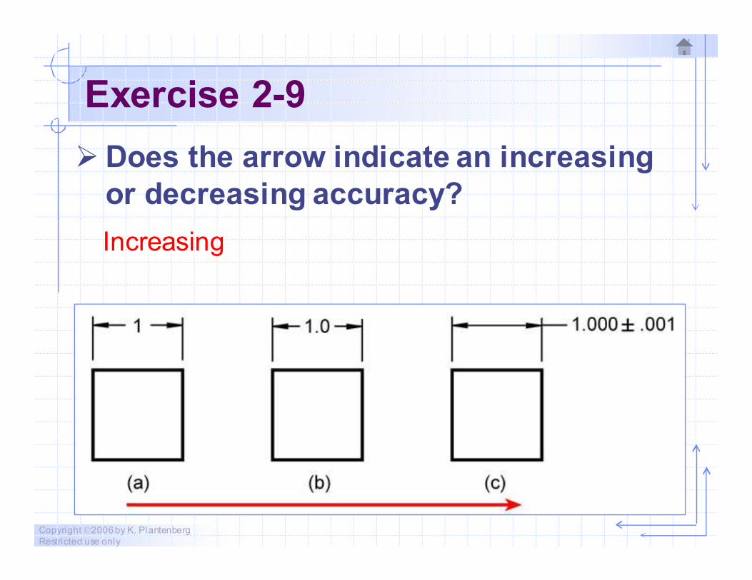
Exercise 2-9
� Does the arrow indicate an increasing
or decreasing accuracy?
Increasing
Copyright ©2006 by K. Plantenberg
Restricted use only
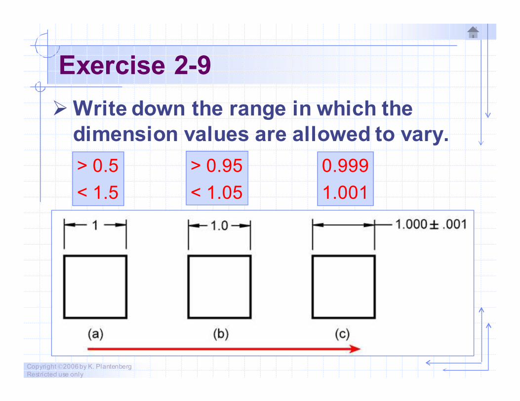
Exercise 2-9
� Write down the range in which the
dimension values are allowed to vary.
> 0.5
< 1.5
> 0.95
< 1.05
0.999
1.001
Copyright ©2006 by K. Plantenberg
Restricted use only
Rounding Off
� The more accurate the dimension the
more expensive it is to manufacture.
→ To cut costs it is necessary to round off
fractional dimensions.
Copyright ©2006 by K. Plantenberg
Restricted use only
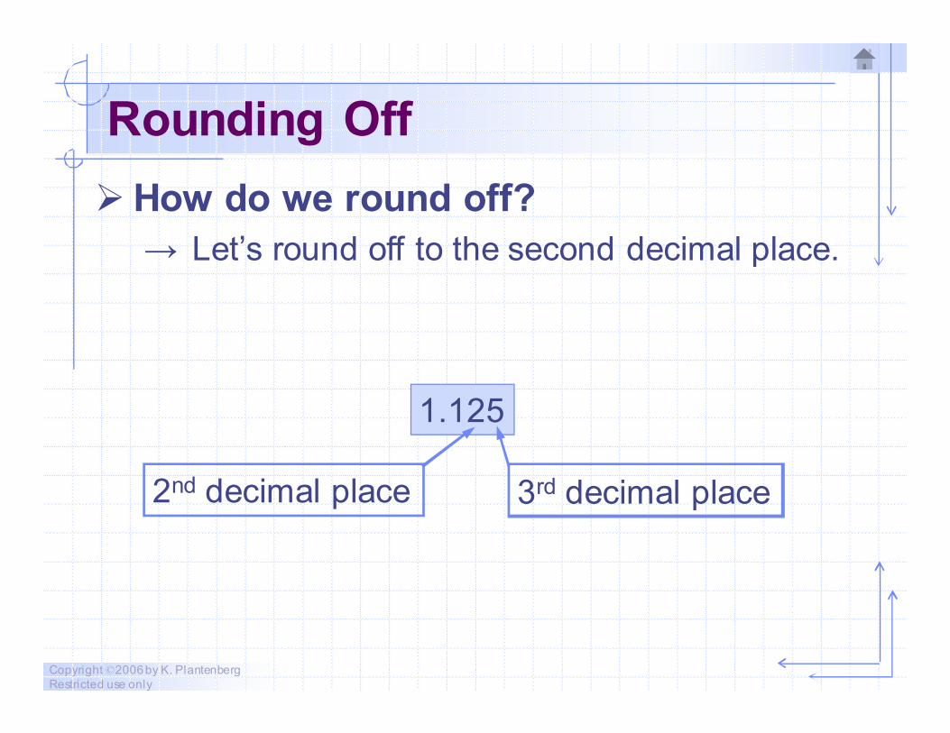
Rounding Off
� How do we round off?
→ Let’s round off to the second decimal place.
1.125
2nd decimal place 3rd decimal place
Copyright ©2006 by K. Plantenberg
Restricted use only
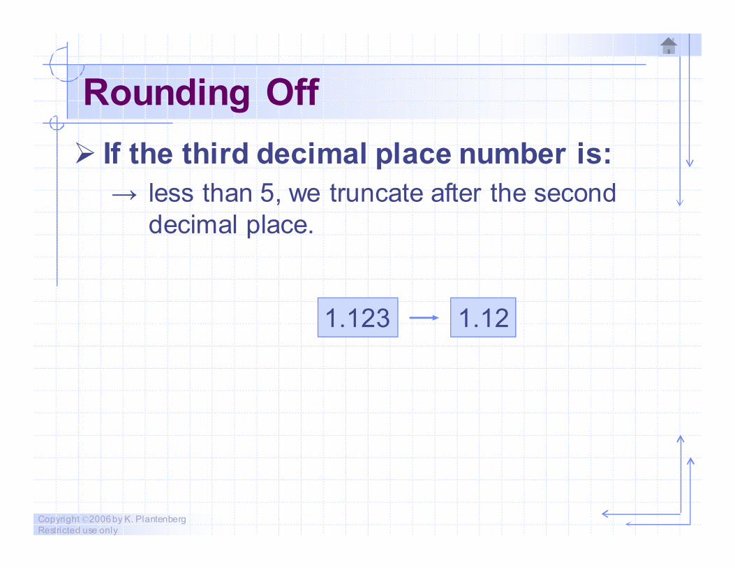
Rounding Off
� If the third decimal place number is:
→ less than 5, we truncate after the second
decimal place.
1.123 1.12
Copyright ©2006 by K. Plantenberg
Restricted use only
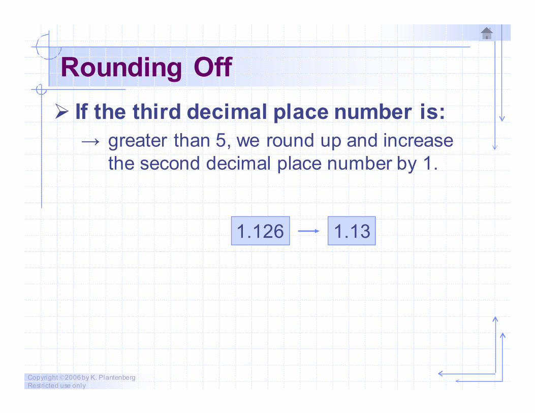
Rounding Off
� If the third decimal place number is:
→ greater than 5, we round up and increase
the second decimal place number by 1.
1.126 1.13
Copyright ©2006 by K. Plantenberg
Restricted use only
Rounding Off
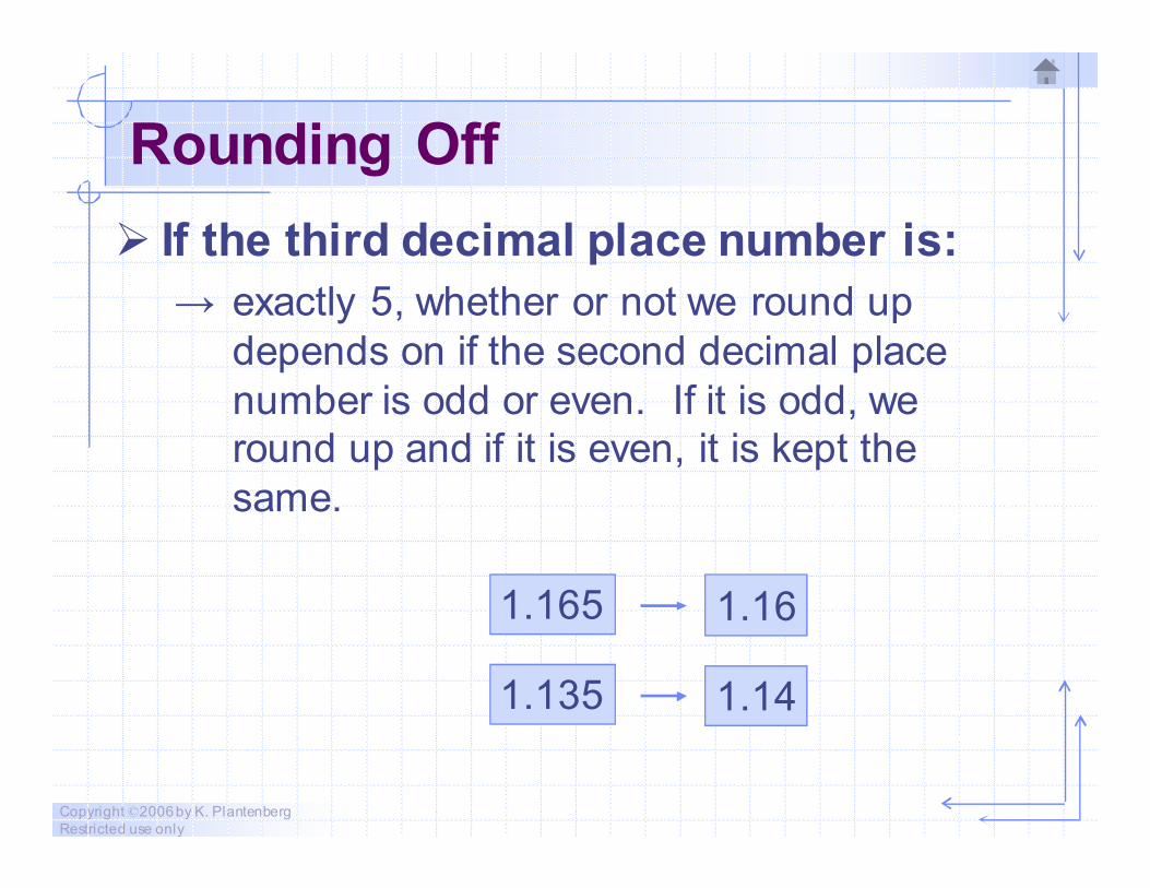
� If the third decimal place number is:
→ exactly 5, whether or not we round up
depends on if the second decimal place
number is odd or even. If it is odd, we
round up and if it is even, it is kept the
same.
1.165 1.16
1.135 1.14
Copyright ©2006 by K. Plantenberg
Restricted use only
Exercise 2-10
Rounding Off
Copyright ©2006 by K. Plantenberg
Restricted use only
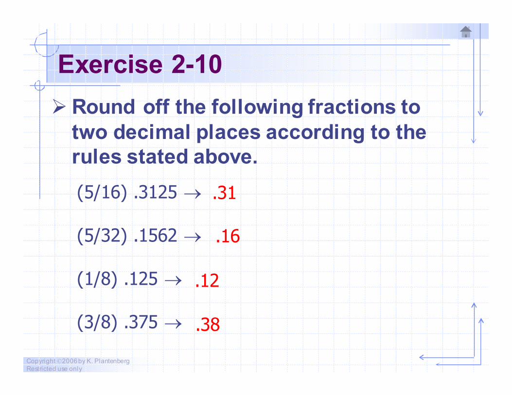
Exercise 2-10
� Round off the following fractions to
two decimal places according to the
rules stated above.
(5/16) .3125 →
(5/32) .1562 →
(1/8) .125 →
(3/8) .375 →
.31
.16
.12
.38
Copyright ©2006 by K. Plantenberg
Restricted use only
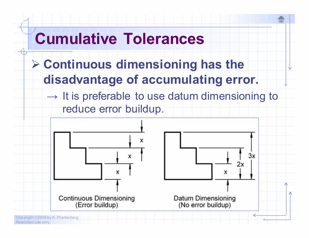
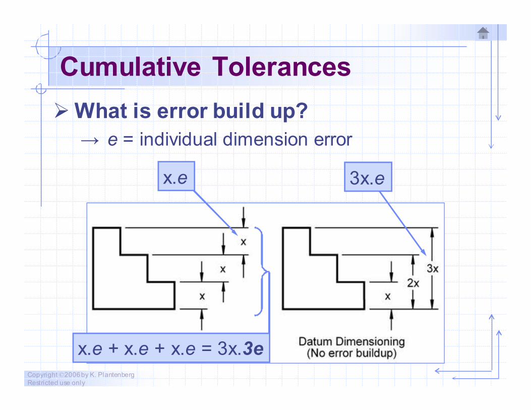
Cumulative Tolerances
� Continuous dimensioning has the
disadvantage of accumulating error.
→ It is preferable to use datum dimensioning to
reduce error buildup.
Copyright ©2006 by K. Plantenberg
Restricted use only
Cumulative Tolerances
� What is error build up?
→ e = individual dimension error
x.e 3x.e
x.e + x.e + x.e = 3x.3e

Copyright ©2006 by K. Plantenberg
Restricted use only
Exercise 2-11
Dimension Choice
Copyright ©2006 by K. Plantenberg
Restricted use only
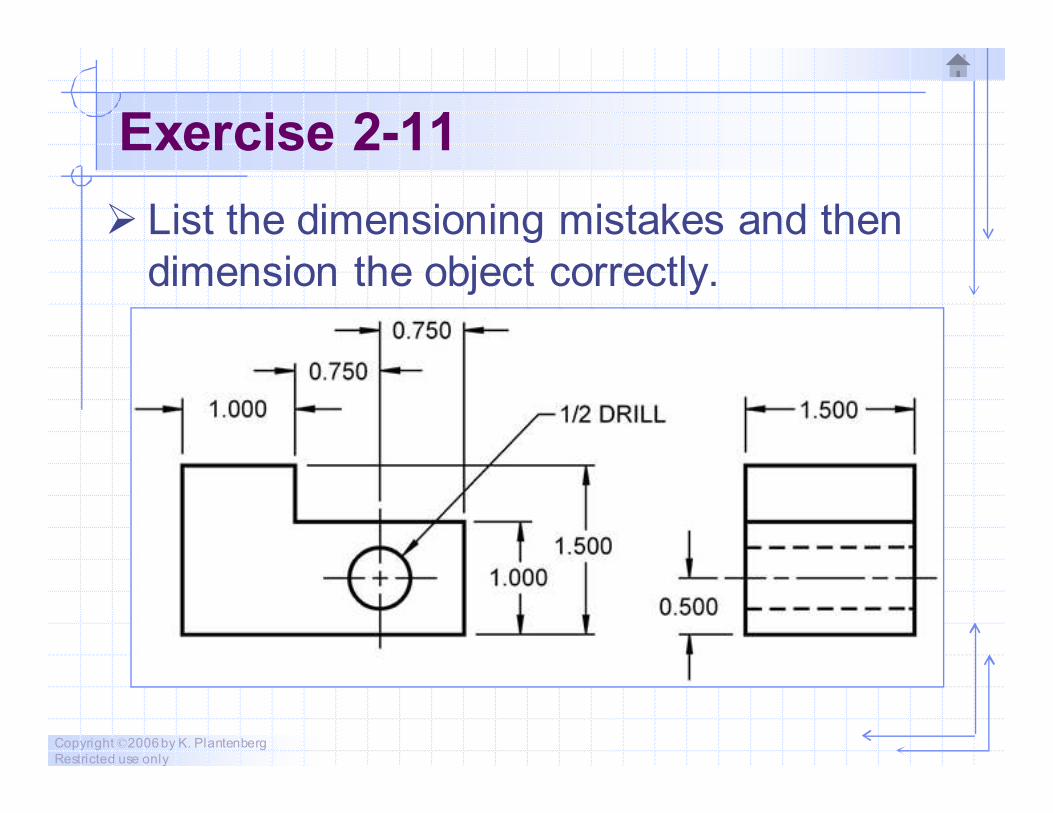
Exercise 2-11
� List the dimensioning mistakes and then
dimension the object correctly.
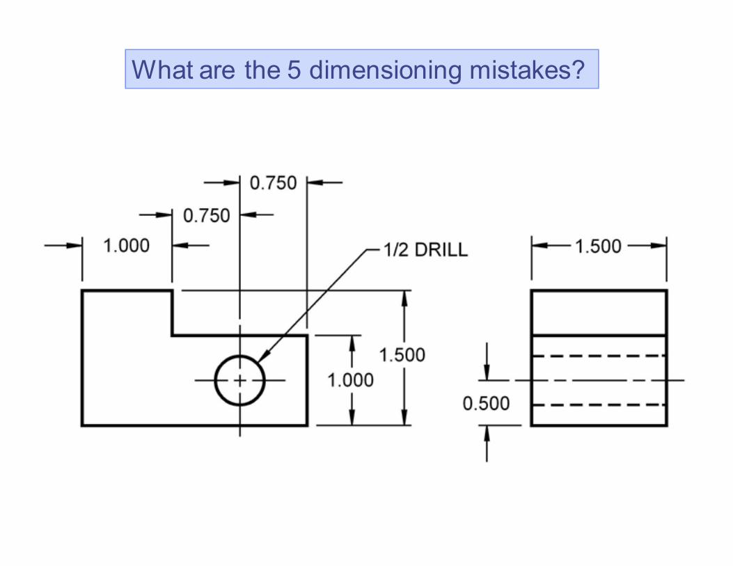
What are the 5 dimensioning mistakes?
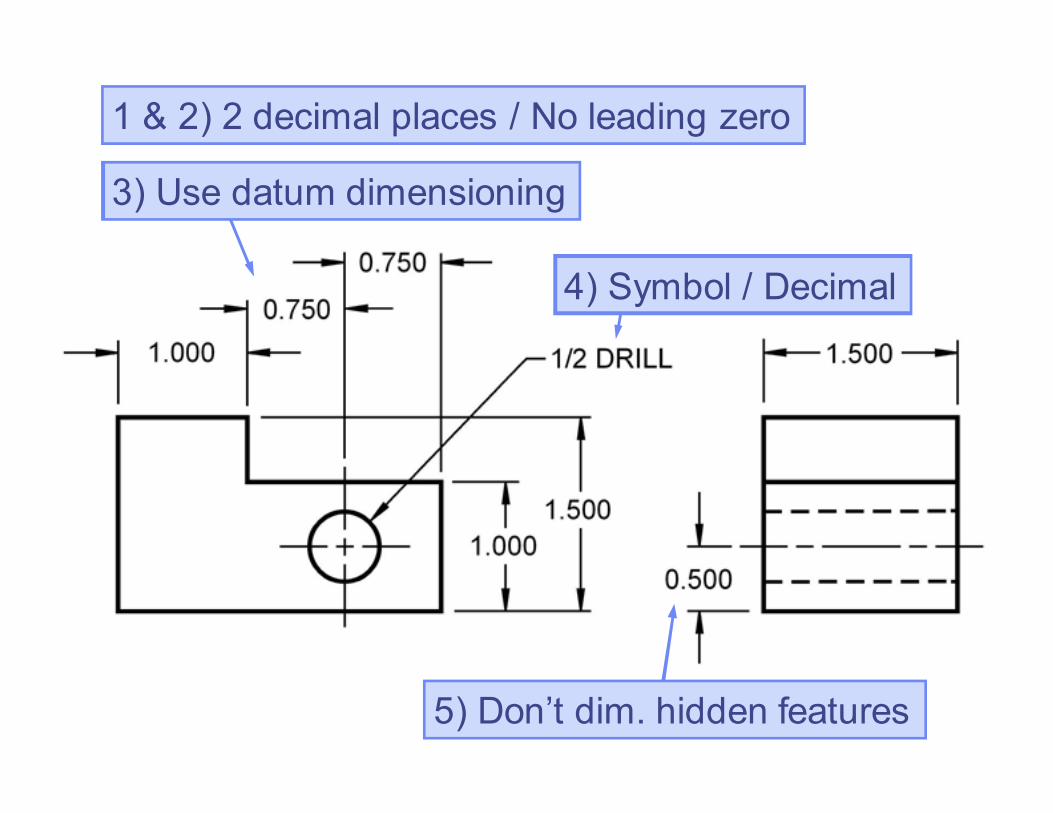
1 & 2) 2 decimal places / No leading zero
4) Symbol / Decimal
3) Use datum dimensioning
5) Don’t dim. hidden features
Correctly Dimensioned

Copyright ©2006 by K. Plantenberg
Restricted use only
Exercise 2-12
Dimensioning 1
Copyright ©2006 by K. Plantenberg
Restricted use only
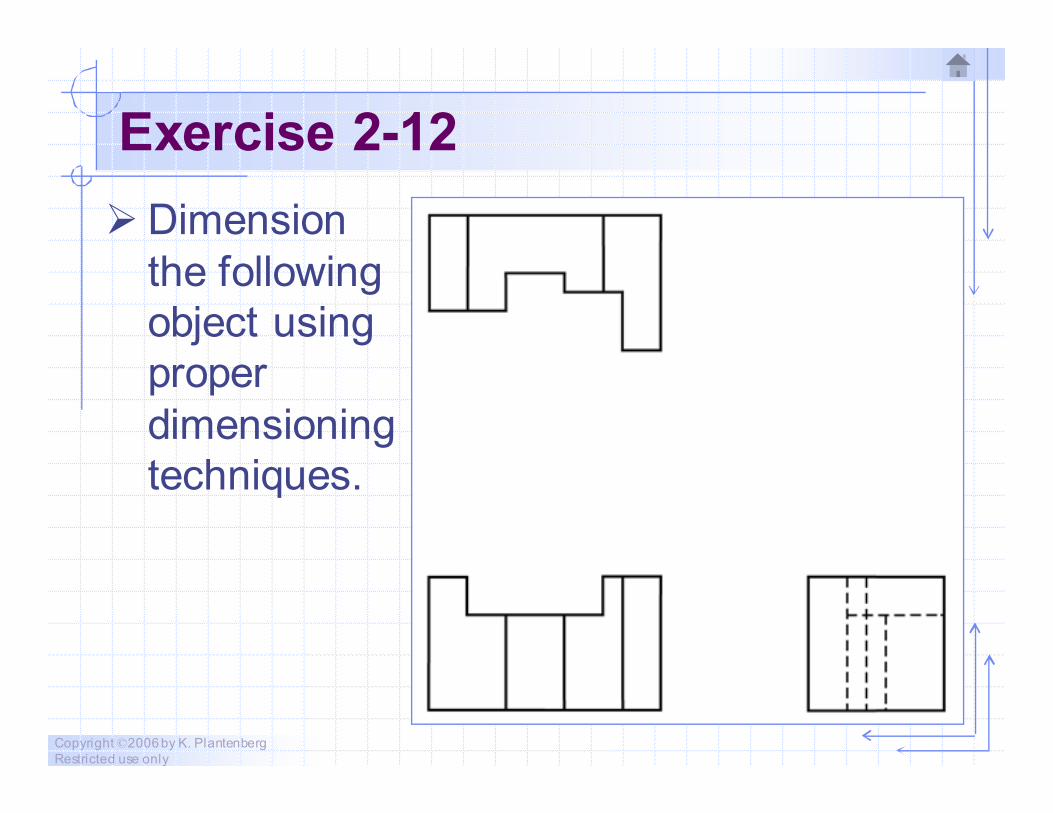
Exercise 2-12
� Dimension
the following
object using
proper
dimensioning
techniques.
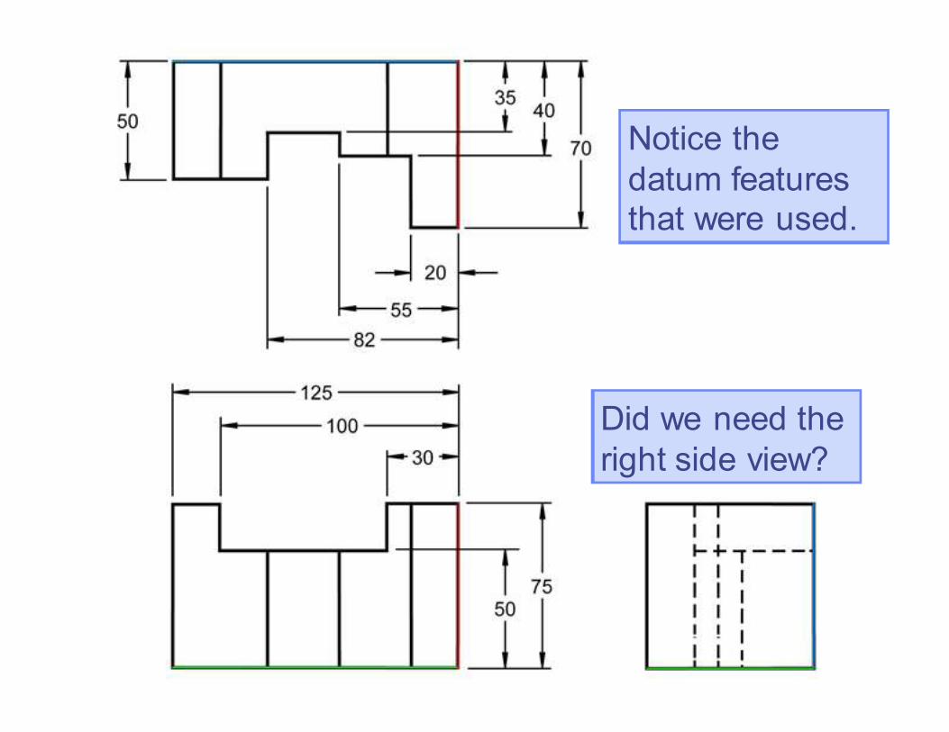
Did we need the
right side view?
Notice the
datum features
that were used.
Copyright ©2006 by K. Plantenberg
Restricted use only
Exercise 2-13
Dimensioning 2
Copyright ©2006 by K. Plantenberg
Restricted use only
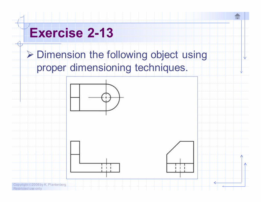
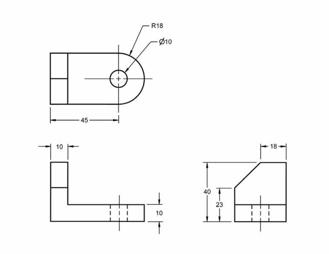
Exercise 2-13
� Dimension the following object using
proper dimensioning techniques.

Copyright ©2006 by K. Plantenberg
Restricted use only
Exercise 2-14
Dimensioning 3
Copyright ©2006 by K. Plantenberg
Restricted use only
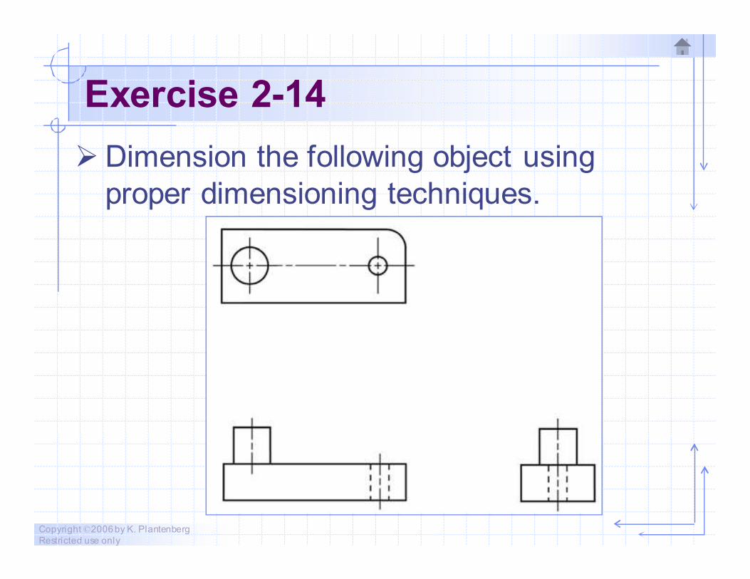
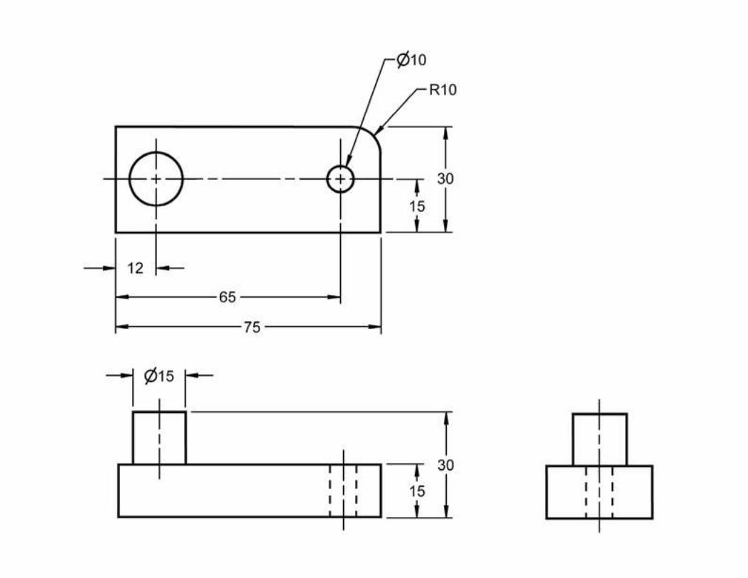
Exercise 2-14
� Dimension the following object using
proper dimensioning techniques.
Copyright ©2006 by K. Plantenberg
Restricted use only
Exercise 2-15
Dimensioning 4
Copyright ©2006 by K. Plantenberg
Restricted use only
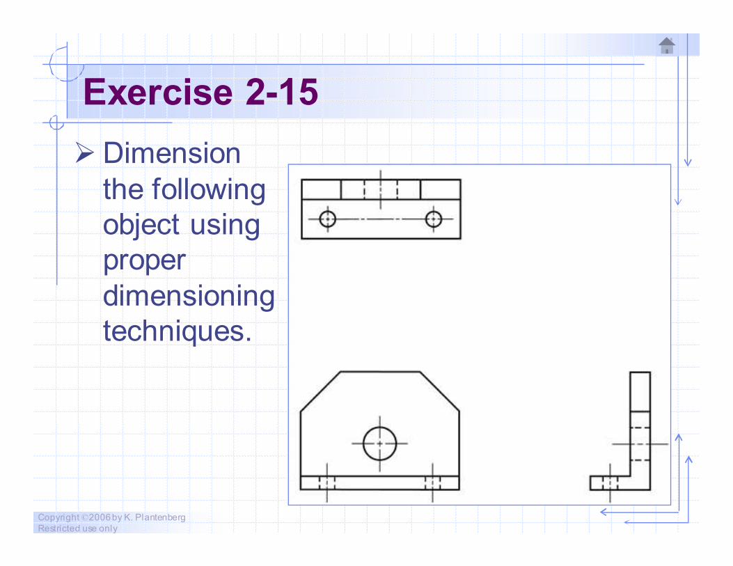
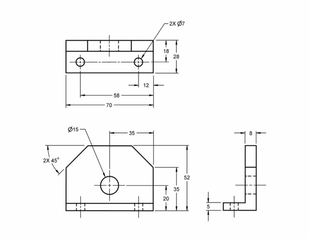
Exercise 2-15
� Dimension
the following
object using
proper
dimensioning
techniques.
Copyright ©2006 by K. Plantenberg
Restricted use only
Dimensioning
The End