chapter 2 experimental rig description · this rotor was assembled using a 9.52 mm (0.375 inch) ......
TRANSCRIPT
7
CHAPTER 2
EXPERIMENTAL RIG DESCRIPTION
Two rotor set-ups were used to evaluate the effectiveness of an AMD to reduce
nonsynchronous vibrations. Initially, experiments were conducted in a single-disk (three-
mass total with two masses representing the AMB rotors) flexible rotor and then further
tests were carried out in a three-disk (five-mass including the radial rotors of the AMBs)
rotor simulating more properly the dynamics of a turbomachine. The rotors are supported
in conventional bearings and two AMB are placed in each rotor, one is used as a source
of excitation while the other provides active control. A detailed description of each of
these set-ups is presented in the following sections.
2.1 Test Rotors
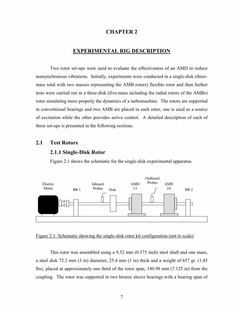
2.1.1 Single-Disk Rotor Figure 2.1 shows the schematic for the single-disk experimental apparatus.
Figure 2.1: Schematic showing the single-disk rotor kit configuration (not to scale)
This rotor was assembled using a 9.52 mm (0.375 inch) steel shaft and one mass,
a steel disk 72.2 mm (3 in) diameter, 25.4 mm (1 in) thick and a weight of 657 gr. (1.45
lbs), placed at approximately one third of the rotor span, 180.98 mm (7.125 in) from the
coupling. The rotor was supported in two bronze sleeve bearings with a bearing span of
AMD 13
Inboard Probes
Outboard Probes
BR 1 Electric Motor Disk
AMD 24 BR 2

8
355.6 mm (14.0 in). The rotor had a total length of 457.2 mm (18.0 inches) and weighs
1.7 kg (3.78 lb).
Two radial rotors representing the rotating part of the AMDs, 34.3 mm (1.35 in)
in diameter, 47.8 mm (1.88 in) long and a weight of 264 gr. (0.58 lbs) each, were
attached to the shaft at approximately the midspan, 232.4 mm (9.150 in) from the
coupling, and at three quarters of the rotor span, 342.9 mm (13.500 in) from the coupling
respectively. The AMD placed at the midspan will be referred as AMD-13, and the
AMD located at the outboard will be referred as AMD-24. Figure 2.2 shows the single-
mass rotor kit.
Figure 2.2: Single-disk rotor kit
2.1.2 Three-Disk Rotor The three-disk rotor was assembled using a steel shaft 9.52 mm (0.375 inch) in
diameter and 641.4 mm (25.25 in) long, one steel disk 72.2 mm (3 in) diameter, 25.4 mm
(1 in) thick and a weight of 657 gr. (1.45 lbs) placed at the midspan, 285.8 mm (11.25 in)
from the coupling and two steel disks 72.2 mm (3 in) diameter, 19.1 mm (0.75 in) thick
and a weight of 493 gr. (1.08 lb) each placed together close to the outboard end of the
shaft, 600 mm (23.63 in) from the coupling. The rotor was supported in two bronze
sleeve bearings with a bearing span of 463.6 mm (18.25 in) and weighs 3.95 kg (8.71 lb).
Figure 2.3 shows the schematic of the three-disk experimental apparatus.
9
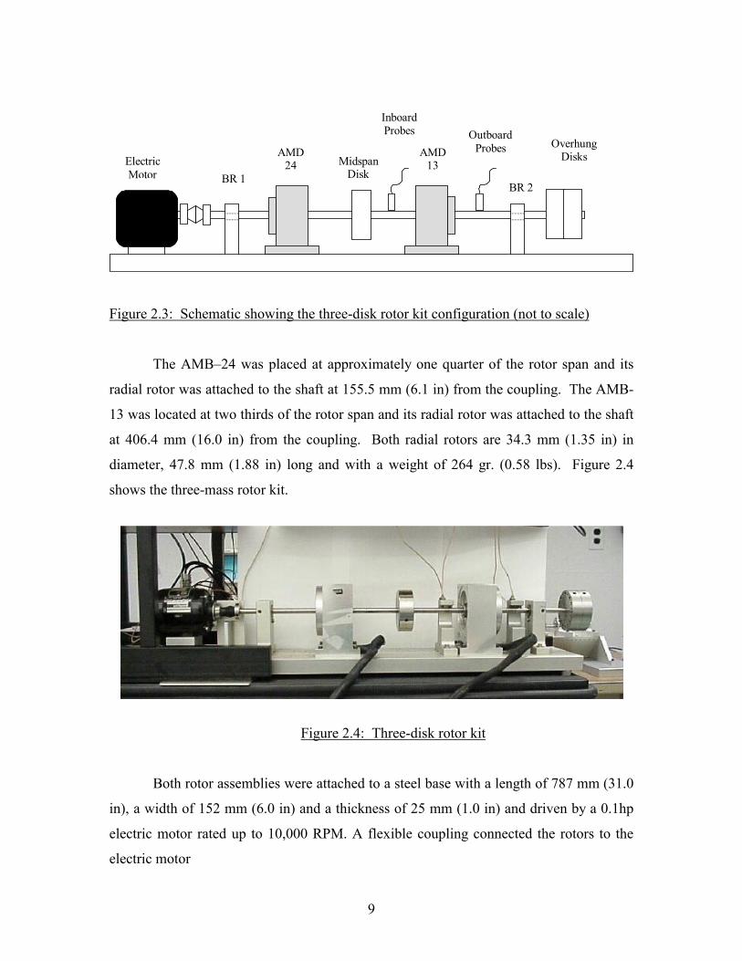
Figure 2.3: Schematic showing the three-disk rotor kit configuration (not to scale)
The AMB–24 was placed at approximately one quarter of the rotor span and its
radial rotor was attached to the shaft at 155.5 mm (6.1 in) from the coupling. The AMB-
13 was located at two thirds of the rotor span and its radial rotor was attached to the shaft
at 406.4 mm (16.0 in) from the coupling. Both radial rotors are 34.3 mm (1.35 in) in
diameter, 47.8 mm (1.88 in) long and with a weight of 264 gr. (0.58 lbs). Figure 2.4
shows the three-mass rotor kit.
Figure 2.4: Three-disk rotor kit
Both rotor assemblies were attached to a steel base with a length of 787 mm (31.0
in), a width of 152 mm (6.0 in) and a thickness of 25 mm (1.0 in) and driven by a 0.1hp
electric motor rated up to 10,000 RPM. A flexible coupling connected the rotors to the
electric motor
AMD 13
AMD 24
Inboard Probes Outboard
Probes
BR 1 BR 2
Electric Motor
Midspan Disk
Overhung Disks

10
2.2 Instrumentation A total of six proximity probes were used in each rotor. One was used as a speed
sensor, connected to the motor speed controller, another one as key-phasor and the other
four distributed in two sets or planes, one horizontal (X) and one vertical (Y) for each
plane, to monitor shaft displacements. The first set identified as the inboard probes and
the second set labeled as outboard probes. For the single-disk rotor, the inboard probes
are located at 136.5 mm (5.375 in) from the coupling and the outboard probes are located
at 298.5 mm (11.75 in) from the same reference. For the three-disk rotor, the inboard
probes were located at 374.7 mm (14.75 in) and the outboard probes at 501.7 mm (19.75
in), both references from the coupling.
The inboard and outboard probes, as well as the key-phasor, were connected to a
Bently Nevada Rotor Kit Proximitor Assembly and from there, the signals were taken to
an interface and then to a Bently Nevada Data Acquisition Interface Unit (DAIU). The
Bently Nevada Automated Diagnostics for Rotating Equipment software (ADRE for
Windows) used on a Gateway Pentium III computer displayed and recorded the data
collected from the two planes of probes.
2.3 Magnetic Bearing Rotor Research Test Stand The equipment used to excite the test rotors and to apply active control, consists
of two radial AMBs, a MB350 controller, the MB Scope software and a MB Research
Box manufactured by Revolve Magnetic Bearings Inc.
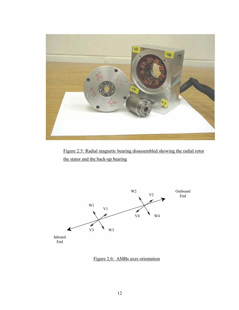
2.3.1 Radial AMBs Two radial AMBs were used in the experimental rig, each one consists of a radial
rotor, a stator, a position sensor ring and a backup bearing. The radial rotor and the stator
are used to levitate the rotor while the sensor ring measures radial position of the shaft for
feedback. The backup bearing provides support to the rotor when the bearing is turned
off or in case of a power loss. The AMBs characteristics are listed in Table 2.1 and their
parts are shown in Figure 2.5. Each Radial AMB has two axes of control. Figure 2.6
shows the orientation of these axes.

11
Table 2.1: Radial magnetic bearing specifications
Bearing Performance Specifications Metric Units Imperial Units
Static load capacity 53 N 12 lbf
Saturation current 3.00 A
Number of poles per quadrant 2
Stator stack length 12.700 mm 0.500 in
Stator OD 70.822 mm 2.788 in
Stator ID 35.052 mm 1.380 in
Rotor OD 34.290 mm 1.350 in
Rotor lamination ID 23.275 mm 0.916 in
Nominal gap 0.381 mm 0.015 in
Small pole width 5.245 mm 0.207 in
Pole height 12.587 mm 0.496 in
Slot width (at ID) 8.417 mm 0.331 in
Pole centerline angle 0.394 rads 22.5 deg
12
Figure 2.5: Radial magnetic bearing disassembled showing the radial rotor
the stator and the back-up bearing
Figure 2.6: AMBs axes orientation
V1
V2
V4
W2
W4
W3
W1
V3
Outboard End
Inboard End

13
2.3.2 MB350 Controller The MB350 is a Proportional-Integral-Derivative (PID) digital control system
with a sampling frequency of 10000 Hz that offers five axis of magnetic bearing control,
two axes per Radial AMB and one axis for a thrust AMB (not used in this research). The
AMBs were connected to the MB350 controller through a machine connector. The
controller, which has built-in amplifiers, takes signals from the sensors and computes the
necessary stabilizing current requested to keep the rotor in the desired position.
2.3.3 MB Scope Software and MB Research
MB Scope is a computer program that allows monitoring internal system
information and is required to perform parameter adjustment of the radial magnetic
bearings. Table 2.2 lists the parameter tuning values used in this research. MB Scope
Software was loaded on an IBM Pentium computer and connected to the MB350
controller through a parallel port connector. This system is also used for signal injection
through the MB Research Box, which is a BNC connector based input/output box. Five
axes (channels) of injection are available, four radial axes, V13, W13, V24 and W24, and
one axial axis (Z2). The MB Research was connected to the MB 350 Controller at the
diagnostic port.
Table 2.2: AMBs parameter tuning values
Parameter Value
Max.current 2.0
Integral Gain 100.0
Proportional Gain 90
Derivative Gain 0.2
Total Gain 0.00008
Low pass 1 1500
LP damping 1 0.707
Top Bias current 0.75
Bottom Bias current 0.75
14
2.4 Undamped Critical Speed Analysis An undamped critical speed analysis was performed using VT Fast, Virginia Tech
Rotordynamic Laboratory code, on the single-disk rotor and the three-disk rotor. The
results are presented below.
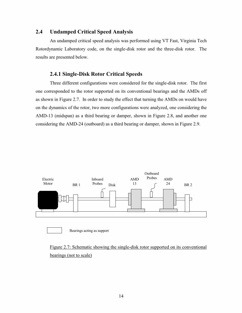
2.4.1 Single-Disk Rotor Critical Speeds Three different configurations were considered for the single-disk rotor. The first
one corresponded to the rotor supported on its conventional bearings and the AMDs off
as shown in Figure 2.7. In order to study the effect that turning the AMDs on would have
on the dynamics of the rotor, two more configurations were analyzed, one considering the
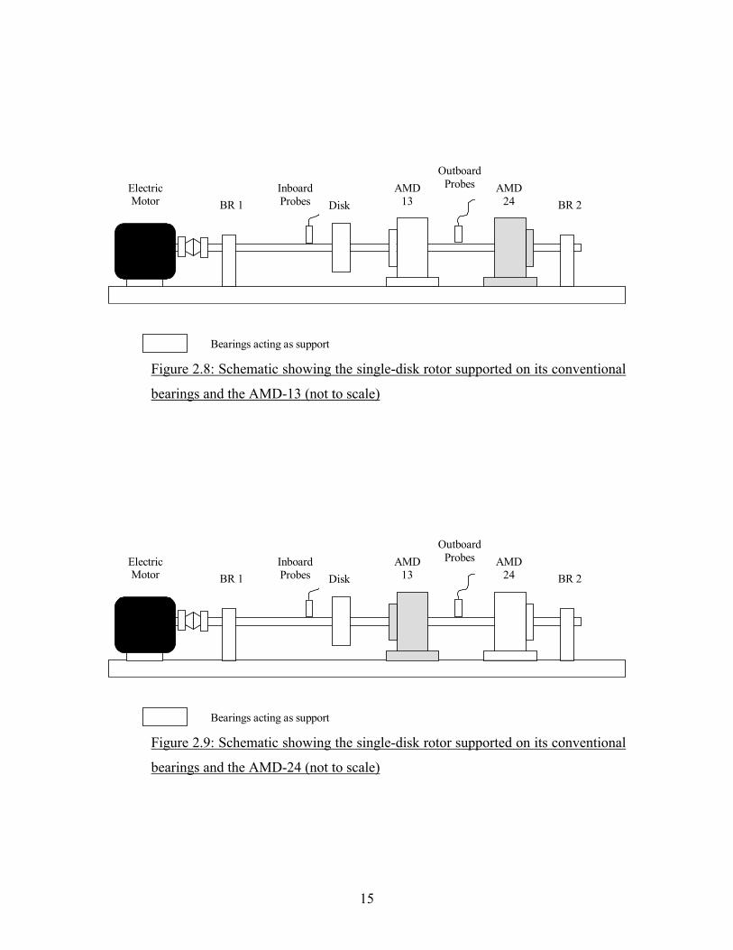
AMD-13 (midspan) as a third bearing or damper, shown in Figure 2.8, and another one
considering the AMD-24 (outboard) as a third bearing or damper, shown in Figure 2.9.
Figure 2.7: Schematic showing the single-disk rotor supported on its conventional
bearings (not to scale)
AMD 13
Inboard Probes
Outboard Probes
BR 1 Electric Motor Disk
AMD 24 BR 2
Bearings acting as support
15
Figure 2.8: Schematic showing the single-disk rotor supported on its conventional
bearings and the AMD-13 (not to scale)
Figure 2.9: Schematic showing the single-disk rotor supported on its conventional
bearings and the AMD-24 (not to scale)
AMD 13
Inboard Probes
Outboard Probes
BR 1 Electric Motor Disk
AMD 24 BR 2
Bearings acting as support
AMD 13
Inboard Probes
Outboard Probes
BR 1 Electric Motor Disk
AMD 24 BR 2
Bearings acting as support
16
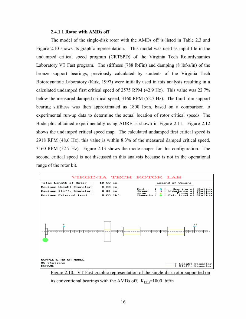
2.4.1.1 Rotor with AMDs off
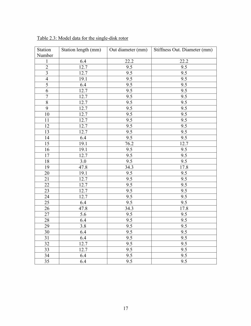
The model of the single-disk rotor with the AMDs off is listed in Table 2.3 and
Figure 2.10 shows its graphic representation. This model was used as input file in the
undamped critical speed program (CRTSPD) of the Virginia Tech Rotordynamics
Laboratory VT Fast program. The stiffness (788 lbf/in) and damping (8 lbf-s/in) of the
bronze support bearings, previously calculated by students of the Virginia Tech
Rotordynamic Laboratory (Kirk, 1997) were initially used in this analysis resulting in a
calculated undamped first critical speed of 2575 RPM (42.9 Hz). This value was 22.7%
below the measured damped critical speed, 3160 RPM (52.7 Hz). The fluid film support
bearing stiffness was then approximated as 1800 lb/in, based on a comparison to
experimental run-up data to determine the actual location of rotor critical speeds. The
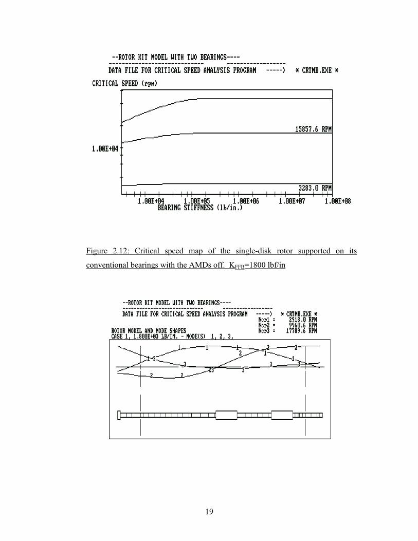
Bode plot obtained experimentally using ADRE is shown in Figure 2.11. Figure 2.12
shows the undamped critical speed map. The calculated undamped first critical speed is
2918 RPM (48.6 Hz), this value is within 8.3% of the measured damped critical speed,
3160 RPM (52.7 Hz). Figure 2.13 shows the mode shapes for this configuration. The
second critical speed is not discussed in this analysis because is not in the operational
range of the rotor kit.
Figure 2.10: VT Fast graphic representation of the single-disk rotor supported on
its conventional bearings with the AMDs off. KFFB=1800 lbf/in
17
Table 2.3: Model data for the single-disk rotor Station Number
Station length (mm) Out diameter (mm) Stiffness Out. Diameter (mm)
1 6.4 22.2 22.2 2 12.7 9.5 9.5 3 12.7 9.5 9.5 4 19.1 9.5 9.5 5 6.4 9.5 9.5 6 12.7 9.5 9.5 7 12.7 9.5 9.5 8 12.7 9.5 9.5 9 12.7 9.5 9.5 10 12.7 9.5 9.5 11 12.7 9.5 9.5 12 12.7 9.5 9.5 13 12.7 9.5 9.5 14 6.4 9.5 9.5 15 19.1 76.2 12.7 16 19.1 9.5 9.5 17 12.7 9.5 9.5 18 3.0 9.5 9.5 19 47.8 34.3 17.8 20 19.1 9.5 9.5 21 12.7 9.5 9.5 22 12.7 9.5 9.5 23 12.7 9.5 9.5 24 12.7 9.5 9.5 25 6.4 9.5 9.5 26 47.8 34.3 17.8 27 5.6 9.5 9.5 28 6.4 9.5 9.5 29 3.8 9.5 9.5 30 6.4 9.5 9.5 31 6.4 9.5 9.5 32 12.7 9.5 9.5 33 12.7 9.5 9.5 34 6.4 9.5 9.5 35 6.4 9.5 9.5

18
Figure 2.11: Bode Plot of the single-disk rotor supported on its conventional
bearings with the AMDs off
19
Figure 2.12: Critical speed map of the single-disk rotor supported on its
conventional bearings with the AMDs off. KFFB=1800 lbf/in

20
Figure 2.13: Mode shapes of the single-disk rotor supported on its conventional
bearings with the AMDs off. KFFB=1800 lbf/in
2.4.1.2 Rotor with the AMD-13 on
A third bearing was added to the previous rotor model at station 19 as shown in
Figure 2.14 to account for the effect of turning the AMD-13 on. The fluid film bearing
stiffness was again considered to be 1800 lbf/in. The equivalent stiffness associated with
the AMD-13 was calculated, as 1470 lbf/in, but it was determined that a stiffness of 800
lbf/in, produced a better match with the experimental results. Figure 2.15 shows the
undamped critical speed map. The calculated undamped first critical speed is 4421 RPM
(73.68 Hz). This value is within 15.8% of the measured damped critical speed, 5120
RPM (85.3 Hz). Figure 2.16 shows the mode shapes for the first, second and third
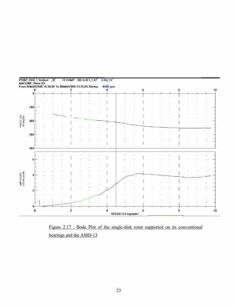
critical speeds. The Bode plot obtained experimentally using ADRE is shown in Figure
2.17. The first undamped critical speed for the single-disk rotor supported on its
conventional bearings is 2918 RPM (48.6 Hz), which means that the AMD-13 added
stiffness to the system, moving the first critical speed to a higher frequency of 5120 RPM
(85.3 Hz).

21
Figure 2.14: VT Fast graphic model of the single-disk rotor supported on its
conventional bearings and the AMD-13. KFFB=1800 lbf/in ; KAMD-13=800 lbf/in
Figure 2.15: Critical speed map for the single-disk rotor supported on its
conventional bearings and the AMD-13. KFFB=1800 lbf/in ; KAMD-13=800 lbf/in

22
Figure 2.16: Mode shapes for the single-disk rotor supported on its conventional
bearings and the AMD-13. KFFB=1800 lbf/in ; KAMD-13=800 lbf/in
23
Figure 2.17 : Bode Plot of the single-disk rotor supported on its conventional
bearings and the AMD-13

24
2.4.1.3 Rotor with the AMD-24 on
A third bearing was added to the model of the single-disk rotor supported on its
conventional bearings at station 26 as shown in Figure 2.18 to mimic the effect of the
AMD-24. The fluid film bearing stiffness was again considered as 1800 lbf/in. The
stiffness of the AMD-24 was again estimated to be 800 lbf/in. Figure 2.19 shows the
undamped critical speed map. The calculated undamped first critical speed is 3514 RPM
(58.6 Hz). This value is within 10.4 % of the damped critical speed, 3880 RPM (64.7
Hz), obtained experimentally using ADRE. Figure 2.20 shows the mode shapes for the
first, second and third critical speeds, and Figure 2.21 shows the bode plot for this
configuration. The first undamped critical speed for this configuration is now at a higher
frequency with respect to the configuration of the single-disk rotor supported on its
conventional bearings, 2918 RPM (48.6 Hz), due to the added stiffness to the system with
the addition of AMD-24.
Figure 2.18: VT Fast graphic model for the single-disk rotor supported on its
conventional bearings and the AMD-24. KFFB=1800 lbf/in ; KAMD-24=800 lbf/in

25
Figure 2.19: Critical speed map of the single-disk rotor supported on its
conventional bearings and the AMD-24. KFFB=1800 lbf/in ; KAMD-24=800 lbf/in
Figure 2.20: Mode shapes of the single-disk rotor supported on its conventional
bearings and the AMD-24. KFFB=1800 lbf/in ; KAMD-24=800 lbf/in

26
Figure 2.21 Bode plot of the single-disk rotor supported on its conventional
bearings and the AMD-24
27
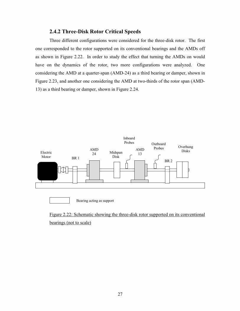
2.4.2 Three-Disk Rotor Critical Speeds Three different configurations were considered for the three-disk rotor. The first
one corresponded to the rotor supported on its conventional bearings and the AMDs off
as shown in Figure 2.22. In order to study the effect that turning the AMDs on would
have on the dynamics of the rotor, two more configurations were analyzed. One
considering the AMD at a quarter-span (AMD-24) as a third bearing or damper, shown in
Figure 2.23, and another one considering the AMD at two-thirds of the rotor span (AMD-
13) as a third bearing or damper, shown in Figure 2.24.
Figure 2.22: Schematic showing the three-disk rotor supported on its conventional
bearings (not to scale)
BR 2
AMD 13
AMD 24
Inboard Probes Outboard
Probes
BR 1 Electric Motor
Midspan Disk
Overhung Disks
Bearing acting as support
28
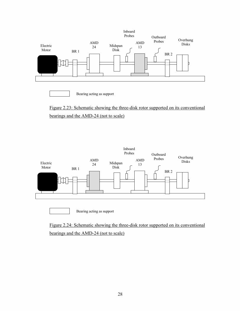
Figure 2.23: Schematic showing the three-disk rotor supported on its conventional
bearings and the AMD-24 (not to scale)
Figure 2.24: Schematic showing the three-disk rotor supported on its conventional
bearings and the AMD-24 (not to scale)
BR 2
AMD 13
AMD 24
Inboard Probes Outboard
Probes
BR 1 Electric Motor
Midspan Disk
Overhung Disks
Bearing acting as support
BR 2
AMD 13
AMD 24
Inboard Probes Outboard
Probes
BR 1 Electric Motor
Midspan Disk
Overhung Disks
Bearing acting as support
29
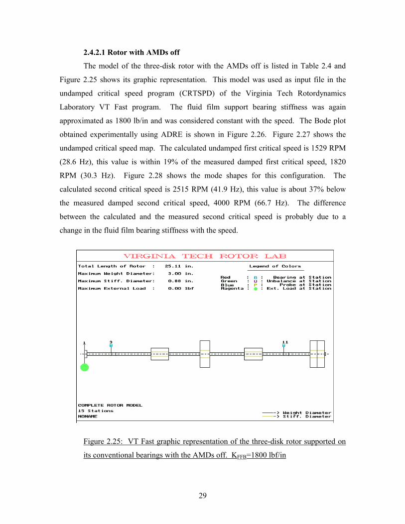
2.4.2.1 Rotor with AMDs off
The model of the three-disk rotor with the AMDs off is listed in Table 2.4 and
Figure 2.25 shows its graphic representation. This model was used as input file in the
undamped critical speed program (CRTSPD) of the Virginia Tech Rotordynamics
Laboratory VT Fast program. The fluid film support bearing stiffness was again
approximated as 1800 lb/in and was considered constant with the speed. The Bode plot
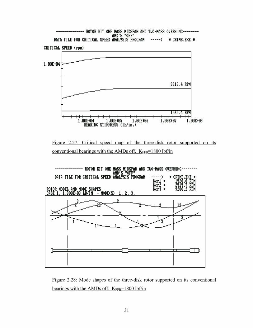
obtained experimentally using ADRE is shown in Figure 2.26. Figure 2.27 shows the
undamped critical speed map. The calculated undamped first critical speed is 1529 RPM
(28.6 Hz), this value is within 19% of the measured damped first critical speed, 1820
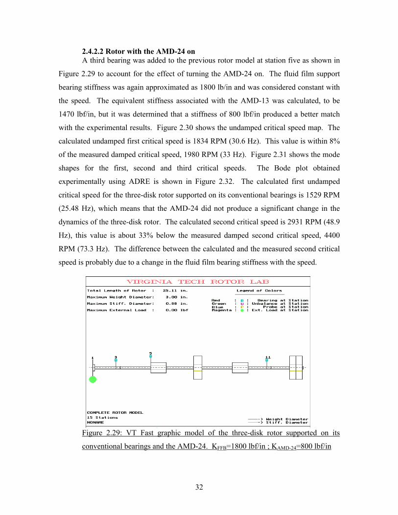
RPM (30.3 Hz). Figure 2.28 shows the mode shapes for this configuration. The
calculated second critical speed is 2515 RPM (41.9 Hz), this value is about 37% below
the measured damped second critical speed, 4000 RPM (66.7 Hz). The difference
between the calculated and the measured second critical speed is probably due to a
change in the fluid film bearing stiffness with the speed.
Figure 2.25: VT Fast graphic representation of the three-disk rotor supported on
its conventional bearings with the AMDs off. KFFB=1800 lbf/in

30
Table 2.4: Model data for the three-disk rotor Station Number
Station length (mm) Out diameter (mm) Stiffness Out. Diameter (mm)
1 6.4 22.2 10.0 2 63.5 9.5 9.5 3 12.7 9.5 9.5 4 92.7 9.5 9.5 5 47.8 34.3 12.7 6 82.3 9.5 9.5 7 25.4 76.2 21.6 8 92.1 9.5 9.5 9 47.8 34.3 12.7 10 55.9 9.5 9.5 11 12.7 9.5 9.5 12 57.2 9.5 9.5 13 19.1 76.2 21.6 14 19.1 76.2 21.6 15 3.2 9.5 9.5
Figure 2.26: Bode Plot of the three-disk rotor supported on its conventional
bearings with the AMDs off
31
Figure 2.27: Critical speed map of the three-disk rotor supported on its
conventional bearings with the AMDs off. KFFB=1800 lbf/in
Figure 2.28: Mode shapes of the three-disk rotor supported on its conventional
bearings with the AMDs off. KFFB=1800 lbf/in
32
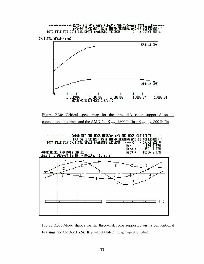
2.4.2.2 Rotor with the AMD-24 on A third bearing was added to the previous rotor model at station five as shown in
Figure 2.29 to account for the effect of turning the AMD-24 on. The fluid film support
bearing stiffness was again approximated as 1800 lb/in and was considered constant with
the speed. The equivalent stiffness associated with the AMD-13 was calculated, to be
1470 lbf/in, but it was determined that a stiffness of 800 lbf/in produced a better match
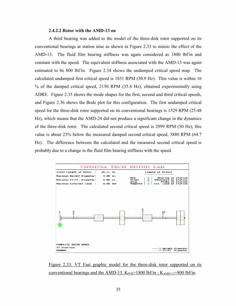
with the experimental results. Figure 2.30 shows the undamped critical speed map. The
calculated undamped first critical speed is 1834 RPM (30.6 Hz). This value is within 8%
of the measured damped critical speed, 1980 RPM (33 Hz). Figure 2.31 shows the mode
shapes for the first, second and third critical speeds. The Bode plot obtained
experimentally using ADRE is shown in Figure 2.32. The calculated first undamped
critical speed for the three-disk rotor supported on its conventional bearings is 1529 RPM
(25.48 Hz), which means that the AMD-24 did not produce a significant change in the
dynamics of the three-disk rotor. The calculated second critical speed is 2931 RPM (48.9
Hz), this value is about 33% below the measured damped second critical speed, 4400
RPM (73.3 Hz). The difference between the calculated and the measured second critical
speed is probably due to a change in the fluid film bearing stiffness with the speed.
Figure 2.29: VT Fast graphic model of the three-disk rotor supported on its
conventional bearings and the AMD-24. KFFB=1800 lbf/in ; KAMD-24=800 lbf/in
33
Figure 2.30: Critical speed map for the three-disk rotor supported on its
conventional bearings and the AMD-24. KFFB=1800 lbf/in ; KAMD-24=800 lbf/in
Figure 2.31: Mode shapes for the three-disk rotor supported on its conventional
bearings and the AMD-24. KFFB=1800 lbf/in ; KAMD-24=800 lbf/in

34
Figure 2.32: Bode Plot of the three-disk rotor supported on its conventional
bearings and the AMD-24
35
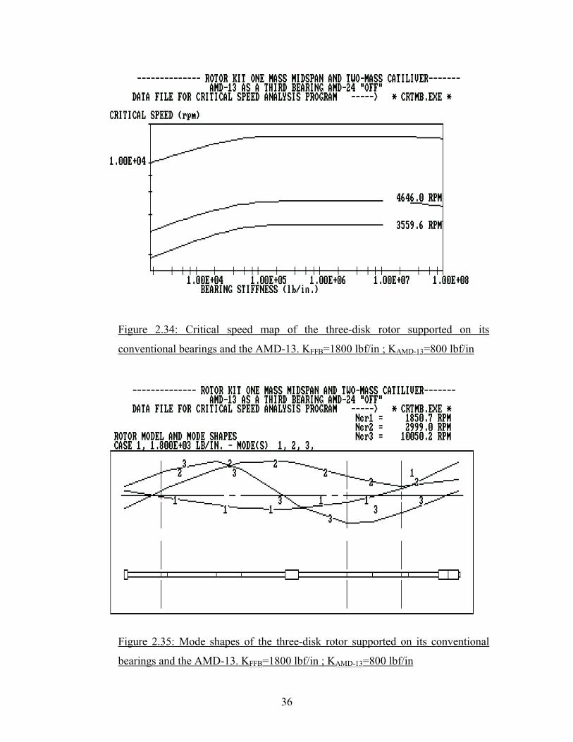
2.4.2.2 Rotor with the AMD-13 on
A third bearing was added to the model of the three-disk rotor supported on its
conventional bearings at station nine as shown in Figure 2.33 to mimic the effect of the
AMD-13. The fluid film bearing stiffness was again considered as 1800 lbf/in and
constant with the speed. The equivalent stiffness associated with the AMD-13 was again
estimated to be 800 lbf/in. Figure 2.34 shows the undamped critical speed map. The
calculated undamped first critical speed is 1851 RPM (30.9 Hz). This value is within 16
% of the damped critical speed, 2150 RPM (35.8 Hz), obtained experimentally using
ADRE. Figure 2.35 shows the mode shapes for the first, second and third critical speeds,
and Figure 2.36 shows the Bode plot for this configuration. The first undamped critical
speed for the three-disk rotor supported on its conventional bearings is 1529 RPM (25.48
Hz), which means that the AMD-24 did not produce a significant change in the dynamics
of the three-disk rotor. The calculated second critical speed is 2999 RPM (50 Hz), this
value is about 23% below the measured damped second critical speed, 3880 RPM (64.7
Hz). The difference between the calculated and the measured second critical speed is
probably due to a change in the fluid film bearing stiffness with the speed.
Figure 2.33: VT Fast graphic model for the three-disk rotor supported on its
conventional bearings and the AMD-13. KFFB=1800 lbf/in ; KAMD-13=800 lbf/in
36
Figure 2.34: Critical speed map of the three-disk rotor supported on its
conventional bearings and the AMD-13. KFFB=1800 lbf/in ; KAMD-13=800 lbf/in
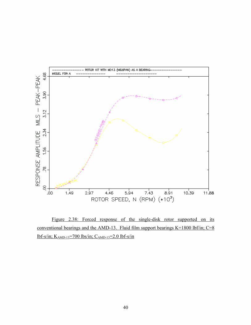
Figure 2.35: Mode shapes of the three-disk rotor supported on its conventional
bearings and the AMD-13. KFFB=1800 lbf/in ; KAMD-13=800 lbf/in

37
Figure 2.36 Bode plot of the three-disk rotor supported on its conventional
bearings and the AMD-13

38
2.5 Forced Response
Results of the critical speed analysis show how the AMDs add stiffness to the
original rotor-bearing system changing the location of the first critical speed to a higher
frequency. A forced response analysis was performed in order to investigate the effect
that the AMDs would have in the synchronous forced response of the single-disk rotor.
2.5.1 Single-Disk Rotor 2.5.1.1 Rotor with AMDs off
The model of the single-disk rotor supported on its conventional bearings with the
AMDs off for forced response is the same listed in Table 2.2 with the addition of an
unbalance of 0.2 gr. placed at the disk (station 15). This model was used as input file in
the forced response code (MODLUND) of the Virginia Tech Rotordynamics Laboratory
VT Fast program. The fluid film support bearing stiffness is approximated as 1800 lb/in,
and the damping was approximated to 8 lb-s/in. Figure 2.37 shows the calculated forced
response plot. For this configuration, the response amplitude expected at the first critical
speed, 3211 RPM (53.5 Hz) is around 3.00 mils pp, and this agrees with the amplitude
obtained experimentally, as shown in the Bode plot of Figure 2.11. The amplification
factors obtained from the forced response analysis (7.2) and from the experiments (7.1)
are also in agreement. It is important to mention that the actual unbalance of the rotor is
unknown and the value considered to perform the forced response analysis (0.2 gr) was
estimated at first and was found to match the experimental data.
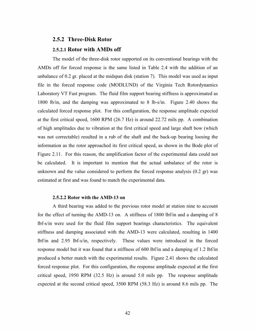
2.5.1.2 Rotor with the AMD-13 on
A third bearing was added to the previous rotor model at station 19 to account for
the effect of turning the AMD-13 on. A stiffness of 1800 lbf/in and a damping of 8 lbf-
s/in were used for the fluid film support bearings characteristics. The equivalent stiffness
and damping associated with the AMD-13 were calculated, resulting in 1400 lbf/in and
2.95 lbf-s/in, respectively. These values were introduced in the forced response model
but it was found that a stiffness of 700 lbf/in and a damping of 2.0 lbf/in produced a
better match with the experimental results. Figure 2.38 shows the calculated forced
response plot. For this configuration, the response amplitude expected at the first critical

39
speed, 5200 RPM (86.7 Hz) is around 3.90 mils pp. The calculated amplitudes agree
with the amplitudes obtained experimentally, as shown in the Bode plot of Figure 2.17.
Figure 2.37: Forced response of the single-disk rotor supported on its
conventional bearings with the AMDs off. Fluid film support bearing K=1800
lbf/in; C=8 lbf-s/in
40
Figure 2.38: Forced response of the single-disk rotor supported on its
conventional bearings and the AMD-13. Fluid film support bearings K=1800 lbf/in; C=8
lbf-s/in; KAMD-13=700 lbs/in; CAMD-13=2.0 lbf-s/in

41
2.5.1.3 Rotor with the AMD-24 on
A third bearing was added to the previous rotor model at station 26 to account for
the effect of turning the AMD-24 on. A stiffness of 1800 lbf/in and a damping of 8 lbf-
s/in were used for the fluid film support bearings characteristics. The equivalent stiffness
and damping associated with the AMD-13 were calculated, resulting in 1400 lbf/in and
2.95 lbf-s/in, respectively. These values were introduced in the forced response model
but it was found that a stiffness of 700 lbf/in and a damping of 1.2 lbf/in produced a
better match with the experimental results. Figure 2.39 shows the calculated forced
response plot. For this configuration, the response amplitude expected at the first critical
speed, 3705 RPM (61.8 Hz) is around 1.6 mils pp. The calculated amplitudes agree with
the amplitudes obtained experimentally, as shown in the Bode plot of Figure 2.21.
Figure 2.39: Forced response of the single-disk rotor supported on its
conventional bearings and the AMD-24. K=1800 lbf/in; C=8 lbf-s/in; KAMD-24=700
lbf/in; CAMD-24=1.2 lbf-s/in
42
2.5.2 Three-Disk Rotor
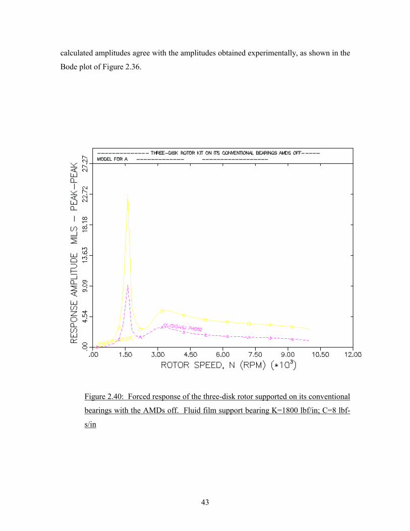
2.5.2.1 Rotor with AMDs off The model of the three-disk rotor supported on its conventional bearings with the
AMDs off for forced response is the same listed in Table 2.4 with the addition of an
unbalance of 0.2 gr. placed at the midspan disk (station 7). This model was used as input
file in the forced response code (MODLUND) of the Virginia Tech Rotordynamics
Laboratory VT Fast program. The fluid film support bearing stiffness is approximated as
1800 lb/in, and the damping was approximated to 8 lb-s/in. Figure 2.40 shows the
calculated forced response plot. For this configuration, the response amplitude expected
at the first critical speed, 1600 RPM (26.7 Hz) is around 22.72 mils pp. A combination
of high amplitudes due to vibration at the first critical speed and large shaft bow (which
was not correctable) resulted in a rub of the shaft and the back-up bearing loosing the
information as the rotor approached its first critical speed, as shown in the Bode plot of
Figure 2.11. For this reason, the amplification factor of the experimental data could not
be calculated. It is important to mention that the actual unbalance of the rotor is
unknown and the value considered to perform the forced response analysis (0.2 gr) was
estimated at first and was found to match the experimental data.
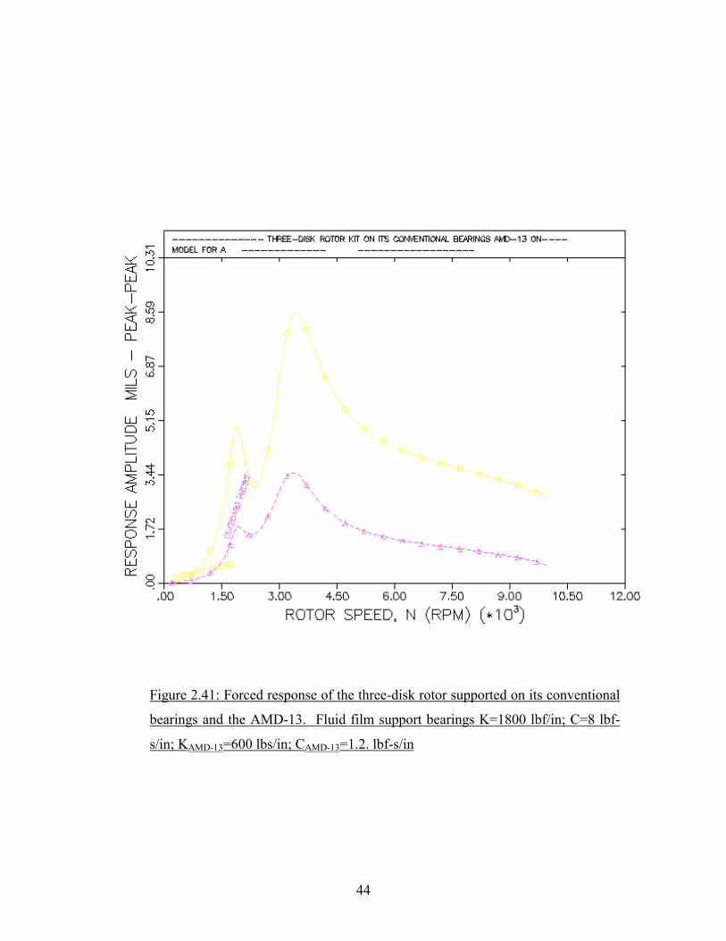
2.5.2.2 Rotor with the AMD-13 on
A third bearing was added to the previous rotor model at station nine to account
for the effect of turning the AMD-13 on. A stiffness of 1800 lbf/in and a damping of 8
lbf-s/in were used for the fluid film support bearings characteristics. The equivalent
stiffness and damping associated with the AMD-13 were calculated, resulting in 1400
lbf/in and 2.95 lbf-s/in, respectively. These values were introduced in the forced
response model but it was found that a stiffness of 600 lbf/in and a damping of 1.2 lbf/in
produced a better match with the experimental results. Figure 2.41 shows the calculated
forced response plot. For this configuration, the response amplitude expected at the first
critical speed, 1950 RPM (32.5 Hz) is around 5.0 mils pp. The response amplitude
expected at the second critical speed, 3500 RPM (58.3 Hz) is around 8.6 mils pp. The
43
calculated amplitudes agree with the amplitudes obtained experimentally, as shown in the
Bode plot of Figure 2.36.
Figure 2.40: Forced response of the three-disk rotor supported on its conventional
bearings with the AMDs off. Fluid film support bearing K=1800 lbf/in; C=8 lbf-
s/in
44
Figure 2.41: Forced response of the three-disk rotor supported on its conventional
bearings and the AMD-13. Fluid film support bearings K=1800 lbf/in; C=8 lbf-
s/in; KAMD-13=600 lbs/in; CAMD-13=1.2. lbf-s/in
45
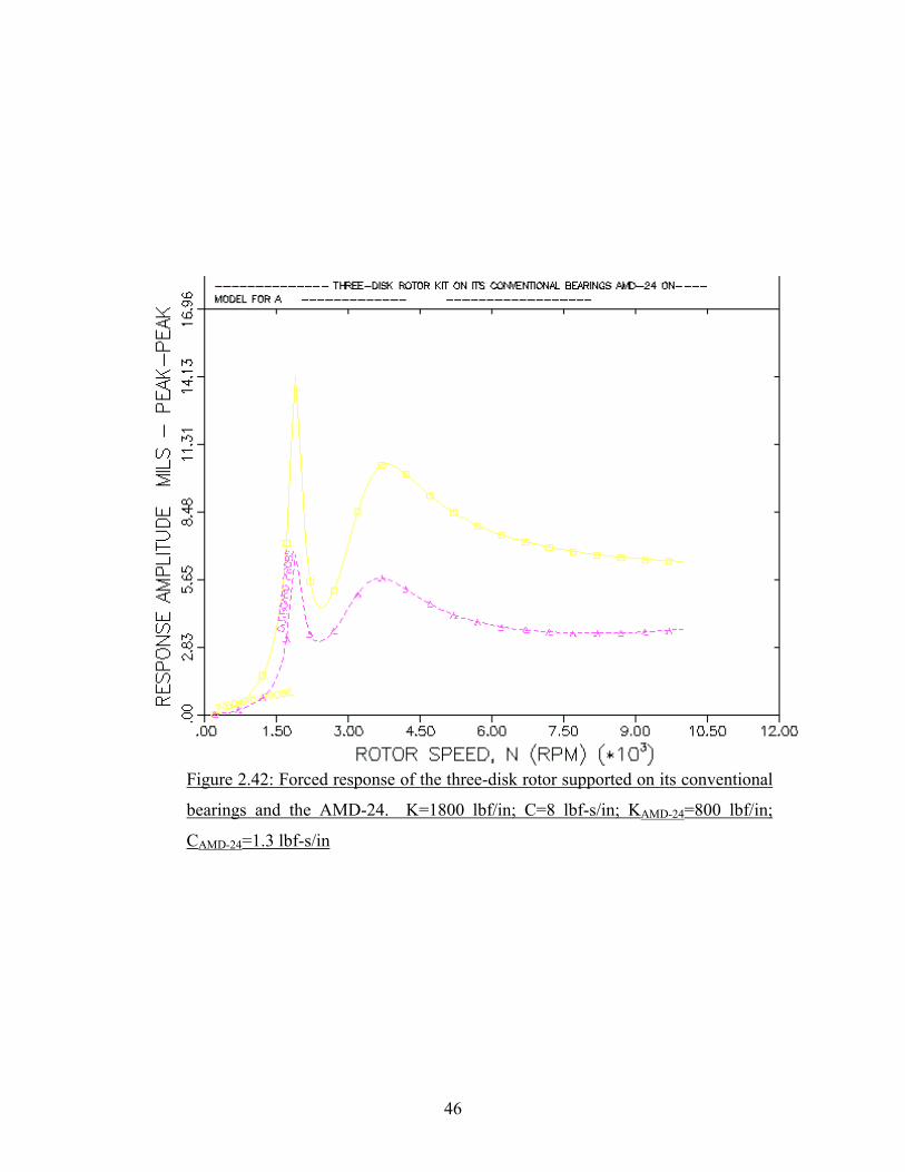
2.5.2.3 Rotor with the AMD-24 on
A third bearing was added to the previous rotor model at station five to account
for the effect of turning the AMD-24 on. A stiffness of 1800 lbf/in and a damping of 8
lbf-s/in were used for the fluid film support bearings characteristics. The equivalent
stiffness and damping associated with the AMD-24 were calculated, resulting in 1400
lbf/in and 2.95 lbf-s/in, respectively. These values were introduced in the forced
response model but it was found that a stiffness of 800 lbf/in and a damping of 1.3 lbf/in
produced a better match with the experimental results. Figure 2.42 shows the calculated
forced response plot. For this configuration, the response amplitude expected at the first
critical speed, 1900 RPM (31.7 Hz) is around 14 mils pp and the response amplitude
expected at the second critical speed, 3850 RPM (64.2 Hz) is around 5.7 mils pp. The
calculated amplitudes are close to the amplitudes obtained experimentally, as shown in
the Bode plot of Figure 2.32.
46
Figure 2.42: Forced response of the three-disk rotor supported on its conventional
bearings and the AMD-24. K=1800 lbf/in; C=8 lbf-s/in; KAMD-24=800 lbf/in;
CAMD-24=1.3 lbf-s/in