chapter 2 fluid power systems - pbworks · pdf file7 basic system components fluid maintenance...
TRANSCRIPT
1
Chapter 2Chapter 2
The Basic SystemThe Basic System
Fluid Power SystemsFluid Power Systems

2
ObjectivesObjectives
Explain the functions of fluid power p psystems. Identify the basic structure of fluid power
systems. List the basic component groups involved in
the structure of fluid power systems.
© Goodheart-Willcox Co., Inc. Permission granted to reproduce for educational use only.3
the structure of fluid power systems.
ObjectivesObjectives
Describe the function of the components pinvolved in basic fluid power systems.
Describe the similarities and differences of hydraulic and pneumatic systems.
Explain the operation of basic hydraulic and
© Goodheart-Willcox Co., Inc. Permission granted to reproduce for educational use only.4
pneumatic systems.

3
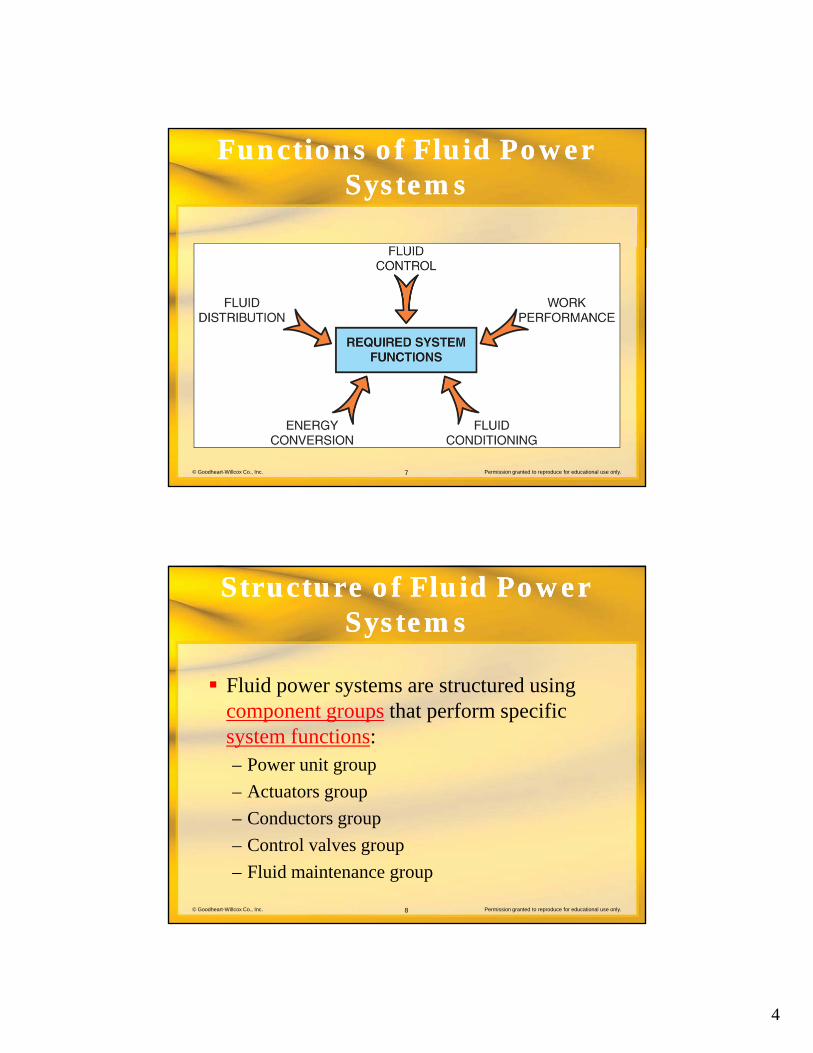
Functions of Fluid Power Functions of Fluid Power Systems Systems
Fluid power systems are made up of Fluid power systems are made up of components designed to perform specific tasks
These components act together to perform desired work
© Goodheart-Willcox Co., Inc. Permission granted to reproduce for educational use only.5
Functions of Fluid Power Functions of Fluid Power SystemsSystems
Fluid power systems perform five functions d i tiduring operation:– Energy conversion
– Fluid distribution
– Fluid control
– Work performance
© Goodheart-Willcox Co., Inc. Permission granted to reproduce for educational use only.6
Work performance
– Fluid maintenance
4
Functions of Fluid Power Functions of Fluid Power SystemsSystems
© Goodheart-Willcox Co., Inc. Permission granted to reproduce for educational use only.7
Structure of Fluid Power Structure of Fluid Power Systems Systems
Fluid power systems are structured using Fluid power systems are structured using component groups that perform specific system functions:– Power unit group
– Actuators group
© Goodheart-Willcox Co., Inc. Permission granted to reproduce for educational use only.8
– Conductors group
– Control valves group
– Fluid maintenance group

5
Basic System Components Basic System Components
Power unit group– Deals primarily with energy conversion
– Consists of:• Prime mover
• Pump or compressor
• Reservoir or receiver
© Goodheart-Willcox Co., Inc. Permission granted to reproduce for educational use only.9
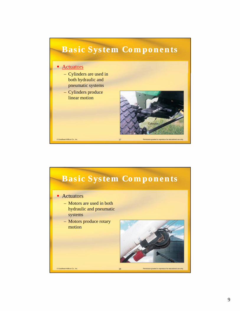
Basic System ComponentsBasic System Components
Actuators group– Performs the work of the system
– Consists of both cylinders and motors
© Goodheart-Willcox Co., Inc. Permission granted to reproduce for educational use only.10

6
Basic System ComponentsBasic System Components
Conductors group– Conductors distribute fluid
throughout the system
– Consists of:• Pipes
• Tubes
© Goodheart-Willcox Co., Inc. Permission granted to reproduce for educational use only.11
• Hoses
Basic System ComponentsBasic System Components
Control valves group– Controls fluid pressure, flow direction, and flow
rate
– Three groups of valves:• Directional control valves
• Pressure control valves
© Goodheart-Willcox Co., Inc. Permission granted to reproduce for educational use only.12
• Flow control valves

7
Basic System ComponentsBasic System Components
Fluid maintenance group– Maintains system fluid by removing dirt, moisture,
and excessive heat
– Filters and other devices are used to perform these functions
© Goodheart-Willcox Co., Inc. Permission granted to reproduce for educational use only.13
Basic System ComponentsBasic System Components
Comparisons can be made between Comparisons can be made between hydraulic and pneumatic systems
System terminology and designs may vary between hydraulic and pneumatic systems
© Goodheart-Willcox Co., Inc. Permission granted to reproduce for educational use only.14

8
Basic System ComponentsBasic System Components
Power unit Power unit– Electric motors and internal combustion
engines are most often the prime movers
– The pump or compressor produces the fluid flow
© Goodheart-Willcox Co., Inc. Permission granted to reproduce for educational use only.15
– Fluid flow is created by internal pressure differences
– Fluid flow transmits energy throughout the system
Basic System ComponentsBasic System Components
Power unit– System reservoir or receiver stores system fluid
– Reservoir/receiver also contributes to system temperature control and fluid cleaning
© Goodheart-Willcox Co., Inc. Permission granted to reproduce for educational use only.16
9
Basic System ComponentsBasic System Components
ActuatorsC li d d i– Cylinders are used in both hydraulic and pneumatic systems
– Cylinders produce linear motion
© Goodheart-Willcox Co., Inc. Permission granted to reproduce for educational use only.17
Basic System ComponentsBasic System Components
ActuatorsM t d i b th– Motors are used in both hydraulic and pneumatic systems
– Motors produce rotary motion
© Goodheart-Willcox Co., Inc. Permission granted to reproduce for educational use only.18

10
Basic System ComponentsBasic System Components
Actuators– Motion is created when pressurized fluid moves an
internal part of the actuators from a high pressure area toward a low pressure area
© Goodheart-Willcox Co., Inc. Permission granted to reproduce for educational use only.19
Basic System ComponentsBasic System Components
Actuators
© Goodheart-Willcox Co., Inc. Permission granted to reproduce for educational use only.20
(Used with permission of CNH America LLC)

11
Basic System ComponentsBasic System Components
Conductors– Pipes
– Tubes
– Hoses
– Transmit system fluid to system components
© Goodheart-Willcox Co., Inc. Permission granted to reproduce for educational use only.21
Basic System ComponentsBasic System Components
Control valves– Directional control valves
• Vary the direction of movement of cylinders and motors
• Change fluid flow paths to and from the actuators
© Goodheart-Willcox Co., Inc. Permission granted to reproduce for educational use only.22

12
Basic System ComponentsBasic System Components
Control valves– Pressure control valves
• Control pressure in a fluid power system
• Restrict fluid flow into a part of the system
• Allow fluid to return to a low pressure area after a desired pressure is reached
© Goodheart-Willcox Co., Inc. Permission granted to reproduce for educational use only.23
Basic System ComponentsBasic System Components
Control valvesFl t l l– Flow control valves
• Control fluid flow rate in a system
• The size of an orifice is adjusted to change flow
© Goodheart-Willcox Co., Inc. Permission granted to reproduce for educational use only.24

13
Basic System ComponentsBasic System Components
Fluid maintenance devices– Filters
– Separators
– Lubricators
– Used to remove contaminates and condition the fluid
© Goodheart-Willcox Co., Inc. Permission granted to reproduce for educational use only.25
– Assure effective system performance and acceptable service life
Basic System Operation Basic System Operation
Hydraulic system operationy y p– Movement of oil originates at the pump
– Low pressure at the pump inlet causes oil to pass through a filter as it flows from the reservoir into the pump
High pressure at the pump outlet forces oil to
© Goodheart-Willcox Co., Inc. Permission granted to reproduce for educational use only.26
– High pressure at the pump outlet forces oil to the directional control valve and on to the actuator
– System work is performed by the actuator

14
Basic System OperationBasic System Operation
Hydraulic system operation– Pressure control valves limit pressure in the system
– Flow control valves control the speed of actuator movement
– Oil is returned to the reservoir to be recirculated through the system
© Goodheart-Willcox Co., Inc. Permission granted to reproduce for educational use only.27
g y
Basic System OperationBasic System Operation
Pneumatic system operation– Movement of air begins at the compressor– As air moves into the system from the atmosphere,
it is:• Filtered• Compressed• Stored in the receiver under pressure
© Goodheart-Willcox Co., Inc. Permission granted to reproduce for educational use only.28
Stored in the receiver under pressure
– Pressurized air is distributed to system workstations

15
Basic System OperationBasic System Operation
Pneumatic system operationPneumatic system operation– At the workstation:
• A pressure regulator sets working pressure
• A filter and lubricator provide final conditioning
– Air then moves through a directional control valve and on to an actuator
© Goodheart-Willcox Co., Inc. Permission granted to reproduce for educational use only.29
valve and on to an actuator
– System work is performed by the actuator
Basic System OperationBasic System Operation
Pneumatic system operationD i t ti fl t l l– During system operation, flow control valves control the speed of actuator movement
– Air is discharged back into the atmosphere after passing through the system
© Goodheart-Willcox Co., Inc. Permission granted to reproduce for educational use only.30

16
Review QuestionReview Question
Fluid power systems are made up of _____ t i i t d i d t f ificontaining parts designed to perform specific
tasks.
component groups
© Goodheart-Willcox Co., Inc. Permission granted to reproduce for educational use only.31
Review QuestionReview Question
The fluid control function of a fluid power t t l t d fl id flsystem controls system pressure and fluid flow
_____ and _____.
rate; direction
© Goodheart-Willcox Co., Inc. Permission granted to reproduce for educational use only.32

17
Review QuestionReview Question
The number and appearance of components in fl id t i i fl d b th ta fluid power system is influenced by the type
of _____, application, and _____.
fluid; power output
© Goodheart-Willcox Co., Inc. Permission granted to reproduce for educational use only.33
Review QuestionReview Question
Fluids are distributed throughout a fluid power t b t f d tsystem by components referred to as _____.
conductors
© Goodheart-Willcox Co., Inc. Permission granted to reproduce for educational use only.34

18
Review QuestionReview Question
Fluid power system filters may be located in f th t i l l ti Li tone or more of three typical locations. List
these three locations.
Intake line; working lines; return lines.
© Goodheart-Willcox Co., Inc. Permission granted to reproduce for educational use only.35
Review QuestionReview Question
In the pneumatic fluid power system, after the i d t i h l t d it kpressurized system air has completed its work,
it is exhausted to the _____.
atmosphere
© Goodheart-Willcox Co., Inc. Permission granted to reproduce for educational use only.36
19
GlossaryGlossary
Actuator– A component used to convert the energy in
hydraulic fluid or compressed air into mechanical linear or rotary motion.
© Goodheart-Willcox Co., Inc. Permission granted to reproduce for educational use only.37
GlossaryGlossary
Component group– A group of commonly designed hydraulic or
pneumatic components offered in a full range of sizes with appropriate accessories.
CompressorThe pneumatic system device that converts the
© Goodheart-Willcox Co., Inc. Permission granted to reproduce for educational use only.38
– The pneumatic system device that converts the energy input of the system prime mover into high-pressure compressed air.

20
GlossaryGlossary
ConductorThe element used in fluid power systems to allow– The element used in fluid power systems to allow the movement of hydraulic fluid or compressed air from component to component. Hose, pipe, and tubing are the most common fluid power conductors.
Control valve– Any valve designed to control fluid pressure flow
© Goodheart-Willcox Co., Inc. Permission granted to reproduce for educational use only.39
– Any valve designed to control fluid pressure, flow rate, or actuator direction in a fluid power system.
GlossaryGlossary
CylinderTh t f li t t d t– The common term for linear actuators used to generate movement and force in fluid power systems.
Directional control valve– Hydraulic and pneumatic control valves that direct
fluid flow to start control direction of movement
© Goodheart-Willcox Co., Inc. Permission granted to reproduce for educational use only.40
fluid flow to start, control direction of movement, and stop system actuators.

21
GlossaryGlossary
Filter– A fluid power component that is used to remove
solid contaminants from both air and liquid. The term is often used to designate the complete component including the filter element, case, and mounting hardware.
© Goodheart-Willcox Co., Inc. Permission granted to reproduce for educational use only.41
GlossaryGlossary
Flow control valveA t d i d t id t l f th t– A component designed to provide control of the rate of flow of air or liquid in hydraulic and pneumatic systems.
© Goodheart-Willcox Co., Inc. Permission granted to reproduce for educational use only.42

22
GlossaryGlossary
Hose– A flexible conductor for carrying hydraulic fluid or
compressed air to actuators.
Lubricator– A device designed to apply a lubricant to a bearing
surface. In pneumatic systems, the lubricator is a
© Goodheart-Willcox Co., Inc. Permission granted to reproduce for educational use only.43
p ycomponent of the FRL unit located at the workstation.
GlossaryGlossary
MotorA t t th t i il d ti– An actuator that primarily produces continuous, rotary motion. These components may be powered by electricity, hydraulics, or pneumatics.
Pipe– Rigid tube made from steel with adequate wall
thickness to be threaded Often used as a conductor
© Goodheart-Willcox Co., Inc. Permission granted to reproduce for educational use only.44
thickness to be threaded. Often used as a conductor in fluid power systems.

23
GlossaryGlossary
Power unitPower unit– The unit in a hydraulic system that provides
energy for the system, moves fluid through the system, provides a safe maximum limit of system pressure, and maintains desired system temperature and fluid cleanliness.
© Goodheart-Willcox Co., Inc. Permission granted to reproduce for educational use only.45
GlossaryGlossary
Pressure control valves– Control valves in a fluid power circuit designed to
protect the system from damage from excessive pressure, provide motion control, and protect operators from unexpected actuator movement.
© Goodheart-Willcox Co., Inc. Permission granted to reproduce for educational use only.46

24
GlossaryGlossary
Pressure regulator– A pneumatic system component used to
control air pressure at the system workstations. The valve maintains a constant, reduced pressure for use by tools and equipment operated at the station.
© Goodheart-Willcox Co., Inc. Permission granted to reproduce for educational use only.47
GlossaryGlossary
Prime mover– The source of energy for any fluid power system.
Commonly used prime movers are electric motors and internal combustion engines.
© Goodheart-Willcox Co., Inc. Permission granted to reproduce for educational use only.48
25
Pump
GlossaryGlossary
– A hydraulic component turned by the prime mover that produces fluid flow, which transmits energy through the system.
Receiver– A tank in a pneumatic system, located close to
© Goodheart-Willcox Co., Inc. Permission granted to reproduce for educational use only.49
A tank in a pneumatic system, located close to the compressor, that stores and assists in conditioning compressed air.
GlossaryGlossary
Reservoir– A component in a hydraulic system that holds
the system fluid not currently in use in the pump, control components, actuators, and lines.
© Goodheart-Willcox Co., Inc. Permission granted to reproduce for educational use only.50

26
GlossaryGlossary
Separator– A component, located in the compressor station
area of a pneumatic system, that is designed to remove condensed water from the compressed air. The unit is often teamed with an aftercooler to optimize moisture removal.
© Goodheart-Willcox Co., Inc. Permission granted to reproduce for educational use only.51
GlossaryGlossary
System functionTh t k l t d b th ti f fl id– The tasks completed by the operation of a fluid power system.
Tube– Generally defined as a long, cylindrical body with
an open center. Tubes are used extensively in the fluid power field as fluid conductors and as
© Goodheart-Willcox Co., Inc. Permission granted to reproduce for educational use only.52
fluid power field as fluid conductors and as component parts, such as the barrel of cylinders.