chapter 2 instruction-level parallelism and its exploitation
Post on 21-Dec-2015
231 views
TRANSCRIPT

Chapter 2
Instruction-Level Parallelism and
Its Exploitation

CSCE 614 Fall 2009 2
• See Subset of the MIPS64 Instructions in the back cover of the textbook.

CSCE 614 Fall 2009 3
Instruction-Level Parallelism (ILP)
• Instructions are evaluated in parallel.• Pipelining• Two approaches to exploiting ILP
– Dynamic & Hardware-dependent (chapter 2)• Intel Pentium Series, Athlon, MIPS
R10000/12000, Sun UltraSPARC III, PowerPC, …
– Static & Software-dependent (Appendix A, Appendix G)
• IA-64, Intel Itanium, embedded processors
CSCE 614 Fall 2009 4
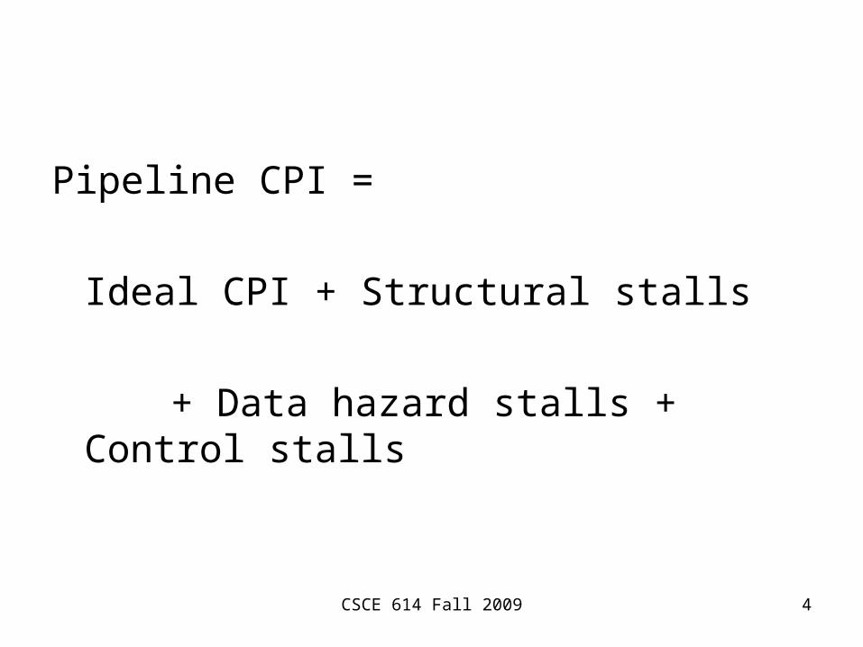
Pipeline CPI =
Ideal CPI + Structural stalls
+ Data hazard stalls + Control stalls
CSCE 614 Fall 2009 5
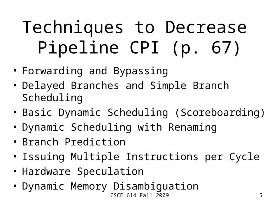
Techniques to Decrease Pipeline CPI (p. 67)
• Forwarding and Bypassing• Delayed Branches and Simple Branch Scheduling• Basic Dynamic Scheduling (Scoreboarding)• Dynamic Scheduling with Renaming• Branch Prediction• Issuing Multiple Instructions per Cycle• Hardware Speculation• Dynamic Memory Disambiguation

CSCE 614 Fall 2009 6
Techniques to Decrease Pipeline CPI (p. 67)
• Loop Unrolling• Basic Compiler Pipeline Scheduling• Compiler Dependence Analysis, Software
Pipelining, Trace Scheduling• Hardware Support for Compiler Speculation

CSCE 614 Fall 2009 7
Data Dependences
• If two instructions are parallel, they can execute simultaneously.
• If two instructions are dependent, they must be executed in order.
• How to determine an instruction is dependent on anther instruction?

CSCE 614 Fall 2009 8
Data Dependences• Data dependences (True data
dependences)
• Name dependences
• Control dependences
• An instruction j is data dependent on instruction i if either – i produces a result that may be used by j, or– j is data dependent on instruction k, and k is
data dependent on i.
CSCE 614 Fall 2009 9
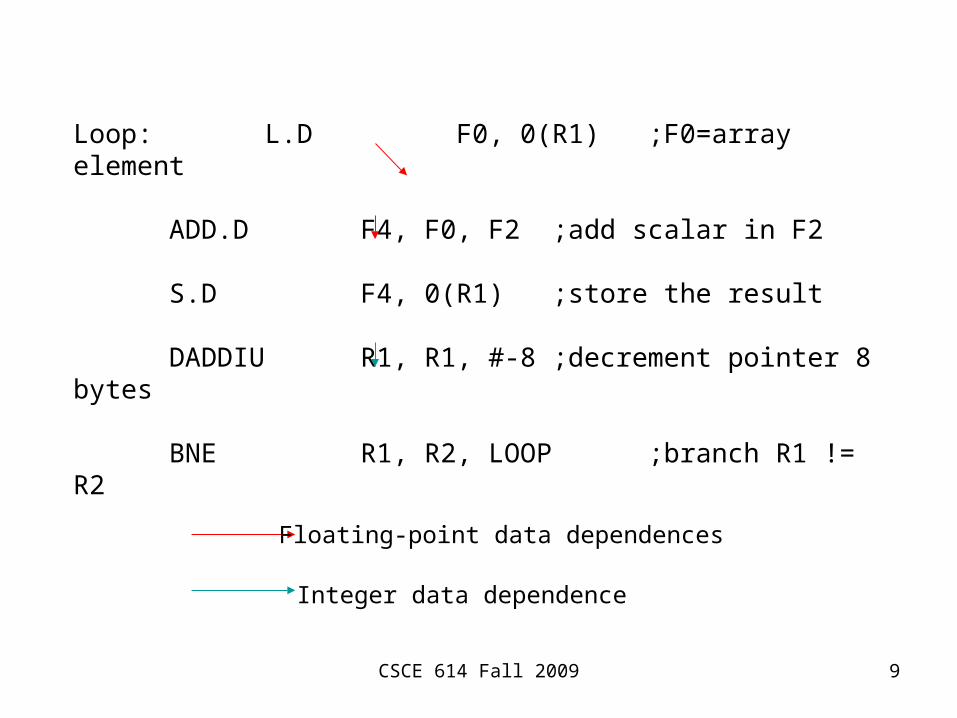
Loop: L.D F0, 0(R1) ;F0=array element
ADD.D F4, F0, F2 ;add scalar in F2
S.D F4, 0(R1) ;store the result
DADDIU R1, R1, #-8 ;decrement pointer 8 bytes
BNE R1, R2, LOOP ;branch R1 != R2
Floating-point data dependences
Integer data dependence

CSCE 614 Fall 2009 10
• The order must be preserved for correct execution.
• If two instructions are data dependent, they cannot execute simultaneously or be completely overlapped.
• Data dependence between DADDIU and BNE => Branch test for the MIPS pipeline in the ID stage (2nd stage).
Data Dependences

CSCE 614 Fall 2009 11
Pipelined Datapath
PCInstruction
memory
4
Registers
Mux
Mux
Mux
ALU
EX
M
WB
M
WB
WB
ID/EX
0
EX/MEM
MEM/WB
Datamemory
Mux
Hazarddetection
unit
Forwardingunit
IF.Flush
IF/ID
Signextend
Control
Mux
=
Shiftleft 2
Mux

CSCE 614 Fall 2009 12
• A dependence– indicates the possibility of a hazard,– determines the order in which results must be
calculated, and– sets an upper bound on how much parallelism
can be possibly be exploited.
Data Dependences
CSCE 614 Fall 2009 13
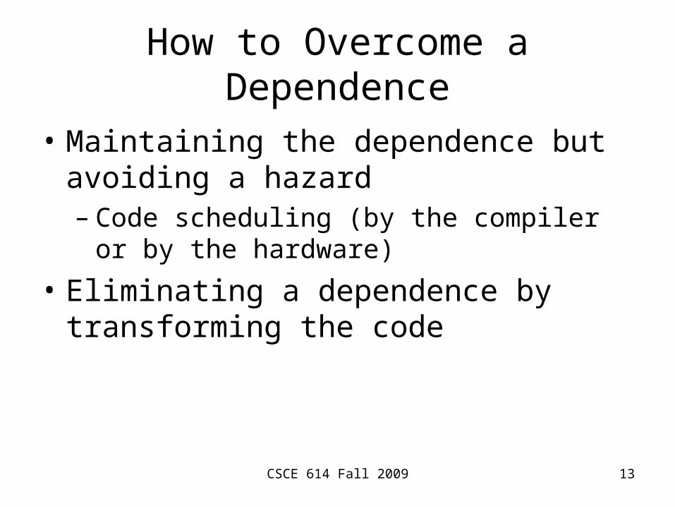
How to Overcome a Dependence
• Maintaining the dependence but avoiding a hazard– Code scheduling (by the compiler or by the
hardware)
• Eliminating a dependence by transforming the code
CSCE 614 Fall 2009 14
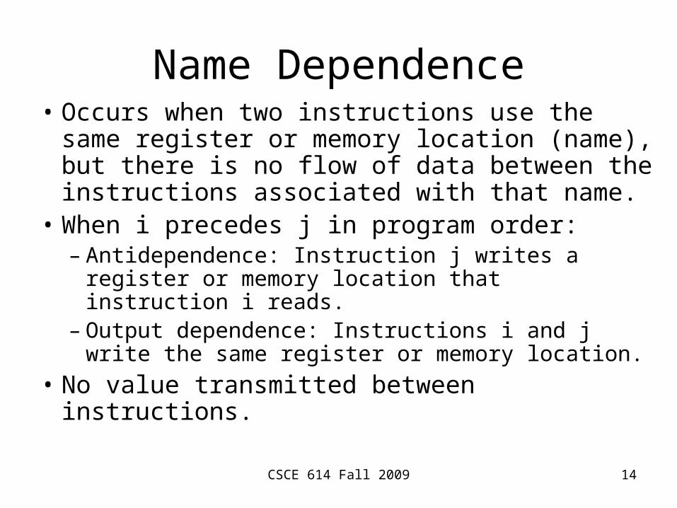
Name Dependence• Occurs when two instructions use the same
register or memory location (name), but there is no flow of data between the instructions associated with that name.
• When i precedes j in program order:– Antidependence: Instruction j writes a register
or memory location that instruction i reads.– Output dependence: Instructions i and j write
the same register or memory location.
• No value transmitted between instructions.
CSCE 614 Fall 2009 15
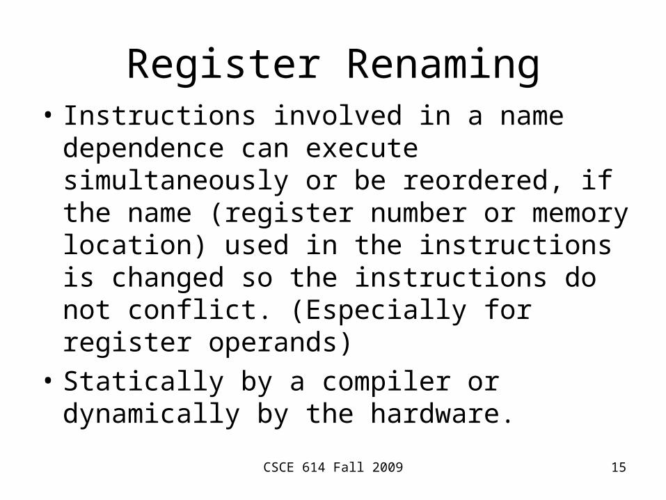
Register Renaming• Instructions involved in a name dependence
can execute simultaneously or be reordered, if the name (register number or memory location) used in the instructions is changed so the instructions do not conflict. (Especially for register operands)
• Statically by a compiler or dynamically by the hardware.

CSCE 614 Fall 2009 16
Hazards
• A hazard is created whenever there is a dependence between instructions, and they are close enough that the overlap during execution, caused by pipelining, or other reordering of instructions, would change the order of access to the operand involved in the dependence.
CSCE 614 Fall 2009 17
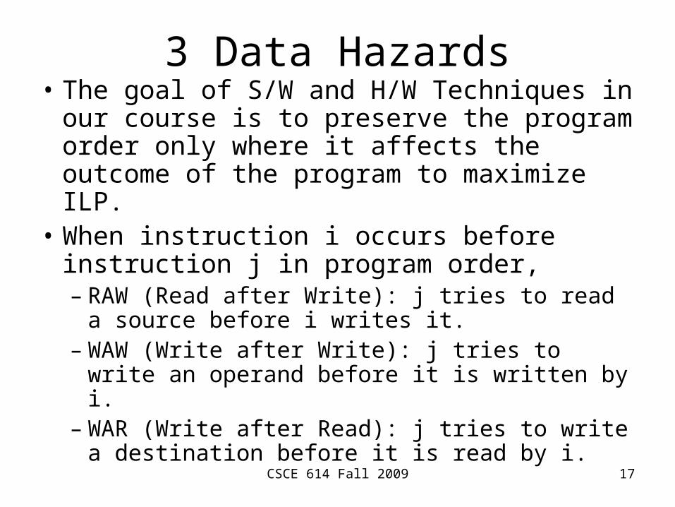
3 Data Hazards• The goal of S/W and H/W Techniques in
our course is to preserve the program order only where it affects the outcome of the program to maximize ILP.
• When instruction i occurs before instruction j in program order,– RAW (Read after Write): j tries to read a
source before i writes it.– WAW (Write after Write): j tries to write an
operand before it is written by i.– WAR (Write after Read): j tries to write a
destination before it is read by i.
CSCE 614 Fall 2009 18
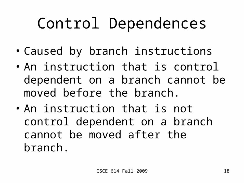
Control Dependences
• Caused by branch instructions
• An instruction that is control dependent on a branch cannot be moved before the branch.
• An instruction that is not control dependent on a branch cannot be moved after the branch.
CSCE 614 Fall 2009 19
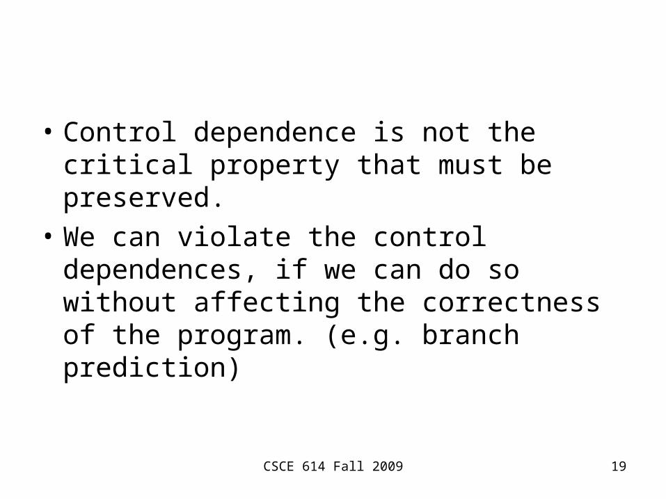
• Control dependence is not the critical property that must be preserved.
• We can violate the control dependences, if we can do so without affecting the correctness of the program. (e.g. branch prediction)
Basic Compiler Techniques for Exposing ILP

CSCE 614 Fall 2009 21
• To avoid a pipeline stall, a dependent instruction must be separated from the source instruction by a distance in clock cycles equal to the pipeline latency of that source instruction.
• Goal: to keep a pipeline full.
Basic Pipeline Scheduling and Loop Unrolling
CSCE 614 Fall 2009 23
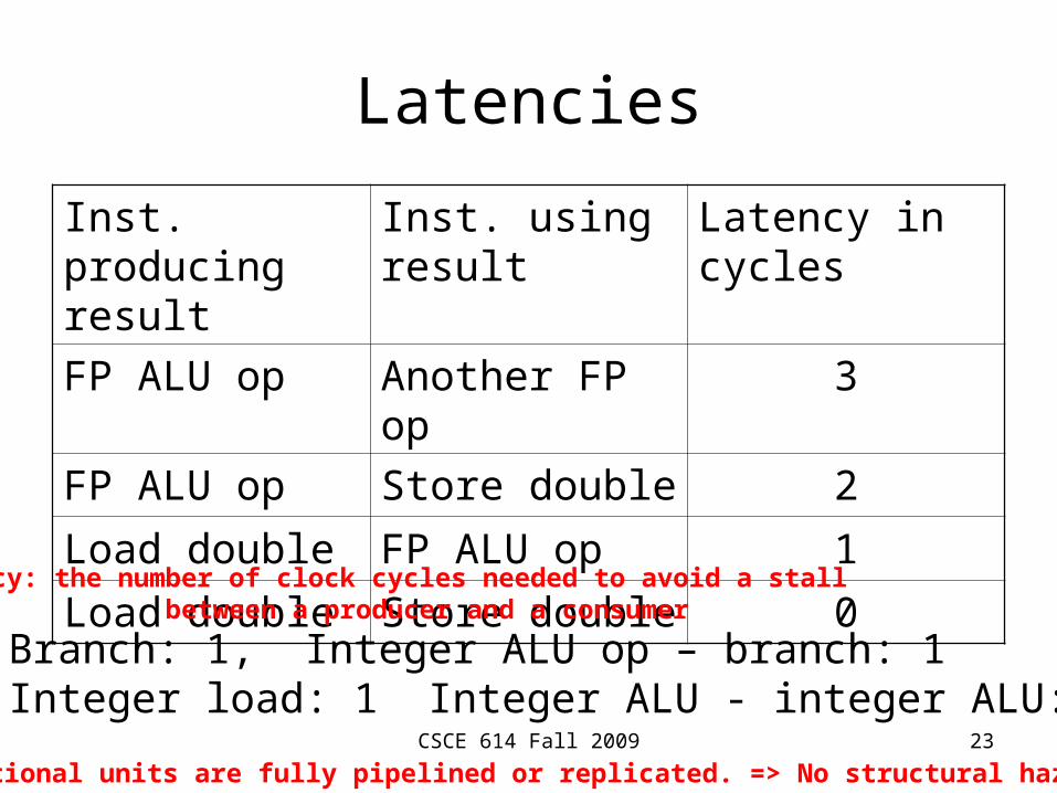
Latencies
Inst. producing result
Inst. using result
Latency in cycles
FP ALU op Another FP op 3
FP ALU op Store double 2
Load double FP ALU op 1
Load double Store double 0
Branch: 1, Integer ALU op – branch: 1Integer load: 1 Integer ALU - integer ALU: 0
Latency: the number of clock cycles needed to avoid a stall between a producer and a consumer
Functional units are fully pipelined or replicated. => No structural hazard
CSCE 614 Fall 2009 24
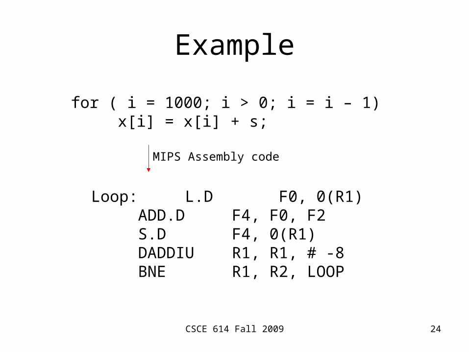
Example
for ( i = 1000; i > 0; i = i – 1)x[i] = x[i] + s;
Loop: L.D F0, 0(R1)ADD.D F4, F0, F2S.D F4, 0(R1)DADDIU R1, R1, # -8BNE R1, R2, LOOP
MIPS Assembly code

CSCE 614 Fall 2009 25
Without Any Scheduling
Clock cycle issued
Loop: L.D F0, 0(R1) 1stall 2
ADD.D F4, F0, F2 3stall 4stall 5
S.D F4, 0(R1) 6DADDIU R1, R1, # -8 7
stall 8BNE R1, R2, LOOP 9
stall 10

CSCE 614 Fall 2009 26
With Scheduling
Clock cycle issued
Loop: L.D F0, 0(R1) 1DADDIU R1, R1, # -8 2ADD.D F4, F0, F2 3
stall 4BNE R1, R2, LOOP 5S.D F4, 8(R1) 6
not trivial
delayed branch
CSCE 614 Fall 2009 27
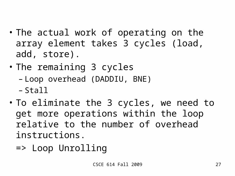
• The actual work of operating on the array element takes 3 cycles (load, add, store).
• The remaining 3 cycles– Loop overhead (DADDIU, BNE)– Stall
• To eliminate the 3 cycles, we need to get more operations within the loop relative to the number of overhead instructions.
=> Loop Unrolling
CSCE 614 Fall 2009 28
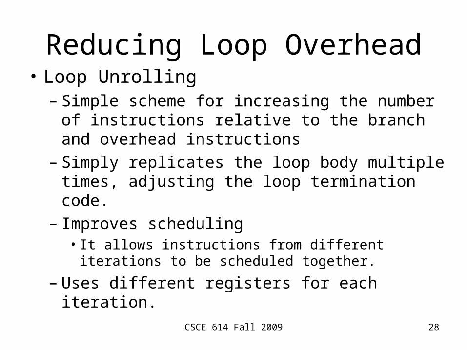
Reducing Loop Overhead• Loop Unrolling
– Simple scheme for increasing the number of instructions relative to the branch and overhead instructions
– Simply replicates the loop body multiple times, adjusting the loop termination code.
– Improves scheduling• It allows instructions from different iterations to be
scheduled together.
– Uses different registers for each iteration.

CSCE 614 Fall 2009 29
Unrolled Loop (No Scheduling)Clock cycle issued
Loop: L.D F0, 0(R1) 1 2ADD.D F4, F0, F2 3 4 5S.D F4, 0(R1) 6 L.D F6, -8(R1) 7 8ADD.D F8, F6, F2 9 10 11S.D F8, -8(R1) 12 L.D F10, -16(R1) 13 14ADD.D F12, F10, F2 15 16 17S.D F12, -16(R1) 18 L.D F14, -24(R1) 19 20ADD.D F16, F14, F2 21 22 23S.D F16, -24(R1) 24DADDIU R1, R1, # -32 25 26BNE R1, R2, LOOP 27 28
DADDIUandBNE
dropped
CSCE 614 Fall 2009 30
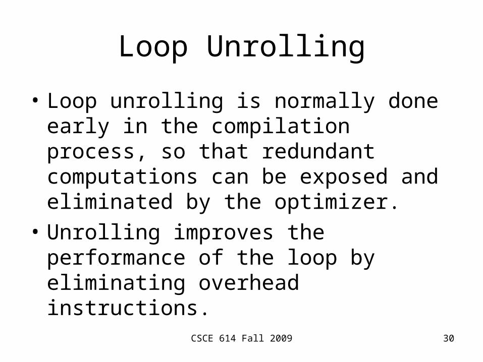
Loop Unrolling
• Loop unrolling is normally done early in the compilation process, so that redundant computations can be exposed and eliminated by the optimizer.
• Unrolling improves the performance of the loop by eliminating overhead instructions.

CSCE 614 Fall 2009 31
Loop Unrolling (Scheduling)Clock cycle issued
Loop: L.D F0, 0(R1) 1L.D F6, -8(R1) 2L.D F10, -16(R1) 3L.D F14, -24(R1) 4ADD.D F4, F0, F2 5ADD.D F8, F6, F2 6ADD.D F12, F10, F2 7ADD.D F16, F14, F2 8S.D F4, 0(R1) 9S.D F8, -8(R1) 10DADDIU R1, R1, # -32 11S.D F12, 16(R1) 12BNE R1, R2, LOOP 13S.D F16, 8(R1) 14
CSCE 614 Fall 2009 32
Summary
• The key to most hardware and software ILP techniques is to know when and how the ordering among instructions may be changed.
• This process must be performed in a methodical fashion either by a compiler or by hardware.
CSCE 614 Fall 2009 33
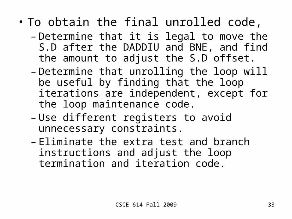
• To obtain the final unrolled code,– Determine that it is legal to move the S.D after
the DADDIU and BNE, and find the amount to adjust the S.D offset.
– Determine that unrolling the loop will be useful by finding that the loop iterations are independent, except for the loop maintenance code.
– Use different registers to avoid unnecessary constraints.
– Eliminate the extra test and branch instructions and adjust the loop termination and iteration code.
CSCE 614 Fall 2009 34
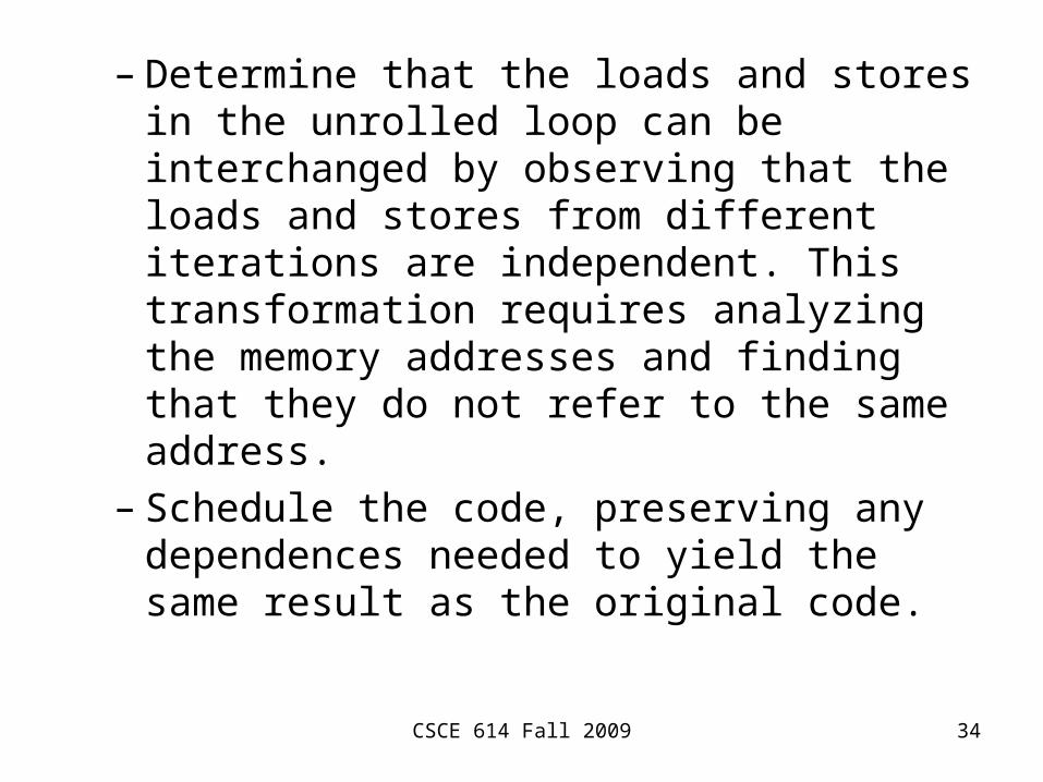
– Determine that the loads and stores in the unrolled loop can be interchanged by observing that the loads and stores from different iterations are independent. This transformation requires analyzing the memory addresses and finding that they do not refer to the same address.
– Schedule the code, preserving any dependences needed to yield the same result as the original code.

CSCE 614 Fall 2009 35
Loop Unrolling I(Unoptimized, No Delayed Branch)
Loop: L.D F0, 0(R1) ADD.D F4, F0, F2S.D F4, 0(R1)DADDIU R1, R1, #-8L.D F0, 0(R1) ADD.D F4, F0, F2S.D F4, 0(R1)DADDIU R1, R1, #-8L.D F0, 0(R1) ADD.D F4, F0, F2S.D F4, 0(R1)DADDIU R1, R1, #-8L.D F0, 0(R1) ADD.D F4, F0, F2S.D F4, 0(R1)DADDIU R1, R1, # -8BNE R1, R2, LOOP
By symbolicallycomputing theintermediate valueof R1
CSCE 614 Fall 2009 36
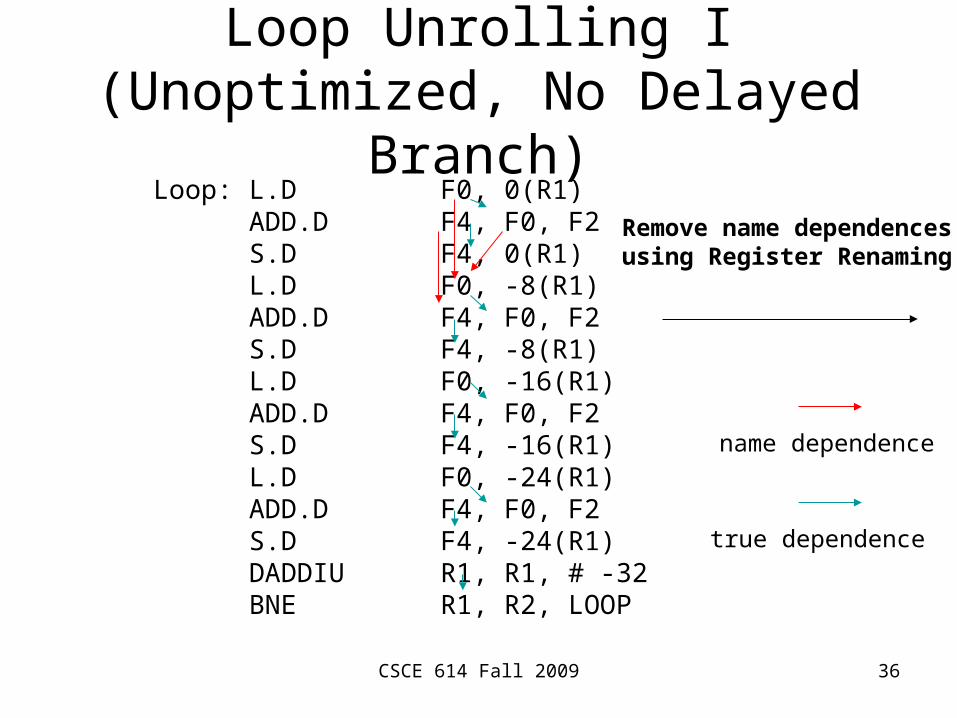
Loop Unrolling I(Unoptimized, No Delayed Branch)
Loop: L.D F0, 0(R1) ADD.D F4, F0, F2S.D F4, 0(R1)L.D F0, -8(R1) ADD.D F4, F0, F2S.D F4, -8(R1)L.D F0, -16(R1) ADD.D F4, F0, F2S.D F4, -16(R1)L.D F0, -24(R1) ADD.D F4, F0, F2S.D F4, -24(R1)DADDIU R1, R1, # -32BNE R1, R2, LOOP
name dependence
true dependence
Remove name dependencesusing Register Renaming
CSCE 614 Fall 2009 37
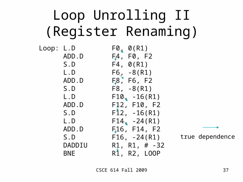
Loop Unrolling II(Register Renaming)
Loop: L.D F0, 0(R1) ADD.D F4, F0, F2S.D F4, 0(R1)L.D F6, -8(R1) ADD.D F8, F6, F2S.D F8, -8(R1)L.D F10, -16(R1) ADD.D F12, F10, F2S.D F12, -16(R1)L.D F14, -24(R1) ADD.D F16, F14, F2S.D F16, -24(R1)DADDIU R1, R1, # -32BNE R1, R2, LOOP
true dependence
CSCE 614 Fall 2009 38
• With the renaming, the copies of each loop body become independent and can be overlapped or executed in parallel.– Problem: potential shortfall in registers
• Register pressure– It arises because scheduling code to increase
ILP causes the number of live values to increase. It may not be possible to allocate all the live values to registers.
– The combination of unrolling and aggressive scheduling can cause this problem.
CSCE 614 Fall 2009 39
• Loop unrolling is a simple but useful method for increasing the size of straight-line code fragments that can be scheduled effectively.