chapter 2 literature review -...
TRANSCRIPT
19
CHAPTER 2
LITERATURE REVIEW
2.1 OPERATIONAL DATA FOR CYLINDRICAL GRINDING
In cylindrical grinding, similar to other metal cutting processes, the
applied speed and feed rates must be adjusted to the operations as well as to
the objectives of the process. Grinding differs, however, from other types of
metal cutting methods in regard to the cutting speed of the wheel in grinding.
Generally cutting speed is not variable and should be maintained at, or close
to the optimum rate.
In establishing the proper process values for grinding, the prime
consideration is the work materials, its condition (hardened or soft) and the
type of operation (roughing or finishing). The other influencing factors are the
characteristics of the grinding machine (stability, power), the specifications of
the grinding wheel, the material allowance, the rigidity and balancing of the
workpiece, as well as several grinding process conditions, such as wet or dry
grinding, the manner of wheel truing etc.
Variables of the cylindrical grinding process, often referred to as
grinding data, comprise the speed of work rotation (measured as the surface
speed of the work), the infeed (in inches per pass for traverse grinding, or
inches per minute for plunge type grinding). This data is for the purpose of
stating the values in setting up a cylindrical grinding process. A brief listing
20
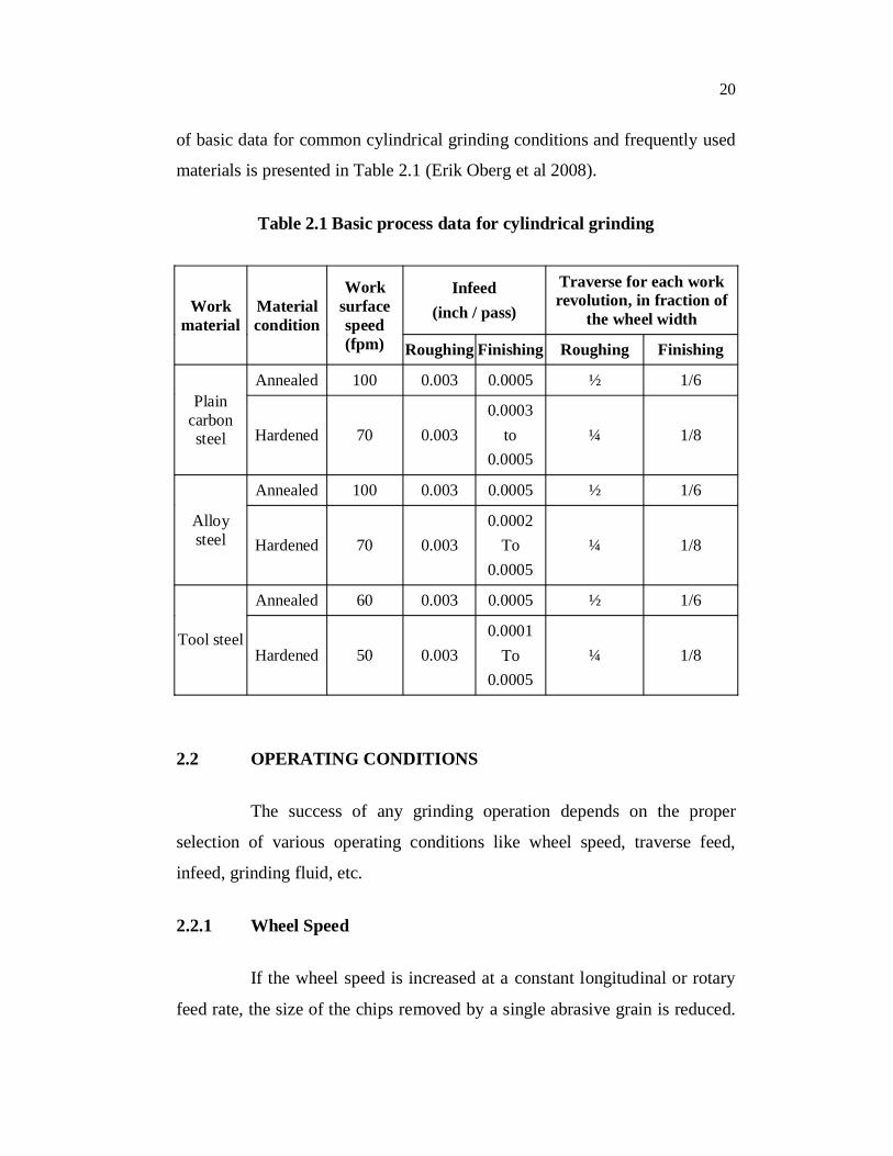
of basic data for common cylindrical grinding conditions and frequently used
materials is presented in Table 2.1 (Erik Oberg et al 2008).
Table 2.1 Basic process data for cylindrical grinding
Workmaterial
Material condition
Worksurfacespeed (fpm)
Infeed (inch / pass)
Traverse for each work revolution, in fraction of
the wheel width
Roughing Finishing Roughing Finishing
Plain carbon steel
Annealed 100 0.003 0.0005 ½ 1/6
Hardened 70 0.0030.0003
to0.0005
¼ 1/8
Alloy steel
Annealed 100 0.003 0.0005 ½ 1/6
Hardened 70 0.0030.0002
To0.0005
¼ 1/8
Tool steel
Annealed 60 0.003 0.0005 ½ 1/6
Hardened 50 0.0030.0001
To0.0005
¼ 1/8
2.2 OPERATING CONDITIONS
The success of any grinding operation depends on the proper
selection of various operating conditions like wheel speed, traverse feed,
infeed, grinding fluid, etc.
2.2.1 Wheel Speed
If the wheel speed is increased at a constant longitudinal or rotary
feed rate, the size of the chips removed by a single abrasive grain is reduced.

21
This reduces the wear of the wheel. If the wheel speed is reduced, the wear is
increased. From this it is clear that from the point of view of wear, it is better
to operate at higher wheel speeds (Optiz and Guhring 1968). However, this is
limited by the allowable speeds at which the wheel can be worked, as well as
the power and rigidity of the grinding machine. Normally, the grinding wheel
speed ranges from 20 to 40 m/sec. The wheel speed also depends upon the
type of grinding operation and the bonding medium of the grinding wheel.
2.2.2 Work Speed
Work speed is the speed at which the workpiece traverses across
the wheel face or rotates between centres. If the work speed is high, the wear
is increased but the heat produced is reduced. Hahn (1956) has stated that
high work speeds are effective in reducing cracking of heat sensitive
materials and may also influence the life of the tool or part. On the other
hand, if the work speed is low the wheel wear decreases but the heat produced
is more. The ratio of wheel speed to work speed is of much importance and it
should be maintained at the proper value. Low work speeds result in local
overheating and bring about deformation or tempering of the hardened
workpiece. This in turn affects the mechanical properties of the workpiece
and very often micro cracks will appear on the workpiece. The increase in
work speed is limited by premature wheel wear and vibrations induced by
wear. Generally, if the wheel wears increases the work speed should be
reduced. If the heat produced is high and clogging occurs, especially with
hard wheels, the work speed should be increased.
2.2.3 Infeed
If the infeed is high, the wheel wear increases and the surface finish
deteriorate, thus affecting the dimensional and geometrical accuracy of the

22
ground workpiece. The material removal rate, however, increases if the infeed
is high.
2.2.4 Traverse Feed
The traversed feed or cross feed rate is governed by the width of
the wheel and the work speed. Normally, the traverse feed rate is adjusted to
two thirds to three fourth of the wheel while grinding steels and three fourth
to five sixths of the wheel width while grinding cast iron. Heavier cross feed
increases the wheel wear and produce rougher finish and slower cross feeds
reduce the wheel wear and produce finer finish. (HMT 1980).
2.2.5 Grinding Fluids
The goal in all conventional metal removal operations is to raise
productivity and reduce costs by machining at the highest practical speed,
consistent accuracy and finish. Many machining operations can be performed
in dry conditions. The proper application of a cutting fluid generally makes
possible, higher cutting speed, greater depth of cut, lengthened tool life,
improved surface finish, increased dimensional accuracy and reduced power
consumption.
Selection of proper cutting fluid for a specific machining situation
requires knowledge of fluid functions, properties and limitations. Cutting
fluid selection deserves as much attention as the choice of machine tool,
tooling speeds and feeds.
In recent years a wide range of grinding fluids has been developed
to satisfy the requirements of new materials of construction and new tool
materials and coatings. The most commonly used grinding fluids are water
based emulsions and grinding oils. Nearly all grinding operations can be

23
carried out with emulsifiable oils. It is important that the fluid is directed to
the interfaces so that it can enter and create a film of low shear strength
between the wheel and work. The quantity of fluid should be ample and may
amount of 15 to 20 litres/min for a medium sized grinding machine.
Generally, the feed quantity of the coolant depends on the length of contact
between the grinding wheel and the workpiece. Larger the contact area, more
should be the quantity of coolant. The width of the stream should be more
than the width of the grinding wheel.
Because of the very high speeds involved in grinding, a film of air
encloses the wheel surface and prevents the penetration of the fluid to the
cutting zone. This air stream can be pierced by supplying the fluid under
pressure or by the design of special nozzles. The nozzle should be as near the
workpiece as possible. Another method of supplying the grinding fluid is
through the voids in the grinding wheel. The fluid is supplied at the center of
the wheel and it moves out through the wheel under the action of centrifugal
force. The main disadvantage is that the fluid is continuously expelled all
along the perimeter of the wheel, instead of only at the cutting zone. Further,
since the pores in the wheel are extremely small, the fluid should be finely
filtered to prevent clogging in the wheel (Guo and Malkin 1992).
2.3 WORK HOLDING ON CYLINDRICAL GRINDING
MACHINES
The manner in which the work is located and held in the machine
during the grinding process determines the configurations of the part which
can be adapted for cylindrical grinding and affects the resulting accuracy of
the ground surfaces. The method of work holding also affects the attainable
production rate, because the mounting and dismounting of the part can
represent a substantial portion of the total operation time.

24
Whatever method is used for holding the part on cylindrical type of
grinding machines, two basic conditions must be satisfied:
(i) the parts should be located with respect to its correct axis of
rotation, and
(ii) the work drive must cause the part to rotate at a specific
speed around the established axis.
The lengthwise location of the part, although controlled, is not too critical in
traverse grinding, however, in plunge grinding, particularly when shoulder
sections are involved, it must be assured with great accuracy.
2.4 IMPORTANCE OF CUTTING FORCE
The cutting force generated in metal cutting has a direct influence
on generation heat, the tool wear or failure, quality of machined surface and
accuracy of the workpiece. It is one of the important characteristic variables
to be monitored in the cutting process. Grinding force is one of the most
important parameters in evaluating the whole process of grinding. Especially,
grinding force is a crucial issue in rough grinding. A large depth of cut and
fast feed rate will cause a high grinding force. They can lead to some
undesired problems, such as errors in size and shape, chatter and burn during
grinding. In general, if only the wheel speed is increased, the average cross-
section of the ground chips decreases, so the grinding force and surface
roughness decrease. The decrease in grinding force results in an improvement
of grinding accuracy. Monitoring the grinding forces is advantageous in
optimizing the process conditions, monitoring the sharpness of the wheel,
grinding fixture design, deformation calculation, improving the process
control, and producing high quality parts.

25
Figure 2.1 Illustration of the force components in cylindrical grinding (Malkin and Guo 2008)
Grinding forces are developed between the wheel and the
workpiece owing to the grinding action. Generally the grinding force is
resolved into three component forces, namely, normal grinding force,
tangential grinding force and a component force acting along the direction of
longitudinal feed which is usually neglected because of its insignificance. The
normal grinding force has an influence upon the surface deformation and
roughness of the workpiece, while the tangential grinding force mainly affects
the power consumption and service life of the grinding wheel. The force
components in cylindrical grinding are illustrated in Figure 2.1.
2.5 FORCE MEASUREMENT IN MACHINING PROCESSES
Measurement of cutting forces is based on three basic principles
i) Measurement of elastic deflection of a body subjected to the
cutting force.
ii) Measurement of elastic deformation, i.e. strain induced by
the force

26
iii) Measurement of pressure developed in a medium by the
force.
The basic principle and general method of measurement is
schematically shown in Figure 2.2.
The cutting force developed in machining operations is estimated
indirectly from a variety of metal cutting dynamometers, mechanical,
hydraulic, pneumatic or several types of electro-mechanical dynamometers.
In the majority of current force measuring techniques, the cutting force is
applied to some elastic member of the dynamometer and the resulting
deflection of the member is measured by using strain measurement
equipment.
Figure 2.2 General principle of measurement
2.5.1 Turning, Milling and Drilling Operations
Generally the dynamometer is strain gauge or piezoelectric type for
measuring three component cutting forces. Oraby and Hayhurst (1990)
designed a compact three component tool shank dynamometer in turning. In
which, the load bearing section has its stiffness reduced by two holes
Reading and recording
Physical variable
Conversion into another suitable variable
Amplification, filtering and
stabilization
Signal
Conditioned signal
27
symmetrically positioned about the center-line, and connected by a narrow
slit. The holes are positioned to enable strain gauges to record the highest
local strains. The electrical strain gauges are mounted on the circular holes to
provide an electrical output proportional to the cutting force. The output
signals due to force have been processed using a computer through strain
gauge amplifiers and analog to digital converter.
Yaldiz and Unsacar (2006) developed a dynamometer such that the
strain gauges are cemented in the octagonal rings. Three full bridges
comprising sixteen strain gauges are used for measuring the component forces
along the primary axes. The strain gauges are connected with the strain
measuring bridges for detection and measurement of strain in terms of
voltage. This voltage provides the magnitude of the cutting force through
calibration.
Korkut (2003) constructed a strain gauge based dynamometer
capable of measuring three-force components during milling operation. In
which the strain gauges are mounted on the octagonal rings. The octagonal
rings are fixed between two plates. The forces on each octagonal ring are
summed up correspondingly to get the total magnitude of all the three forces
in X, Y and Z direction respectively. Although these kind of table
dynamometers provides accurate and effective force measurement, they are
more suitable for laboratory use rather than practical application on
production machines, due to the limitations of workpiece size, mounting
constraints, high sensitive to overload, and high cost. To overcome the
limitations of workpiece mass and size, Albrecht et al (2005) presented a
method of measuring cutting forces from the displacements of rotating
spindle shafts. The cutting forces are measured via a capacitance sensor
installed in the spindle housing using the radial displacements of the rotating
spindle shaft. It is also concluded that, this measurement system is insensitive
28
to overload and not subjected to wear because the sensors are not in contact
with the rotating spindle.
Karabay (2007) developed a drilling dynamometer to measure the
torque and thrust force with three octagonal rings. One of these was used as a
support and the other two were cemented with eight strain gauges. The strain
gauges are connected in this way to measure the thrust force and torque
without any interference. Finally it is concluded that, the force measured
using the dynamometer was good agreement with the force obtained from the
empirical relation.
Totis et al (2010) developed a dynamometer for measuring
individual cutting edge forces in face milling. The device is capable of
providing independent tri-axial cutting force information from each cutting
edge. In addition, cutting inserts are interchangeable and adjustable, and the
device is compatible to different spindle adaptors.
2.5.2 Grinding
There are certain problems which are peculiar to cylindrical
grinding operation. Due to rotation of both the wheel and the workpiece there
are difficulties in physically locating the dynamometer. But, in surface
grinding the dynamometer can be mounted on the table without any
difficulties. In cylindrical grinding, if the dynamometer forms a part of the
rotating workpiece, a transmitter is essential to pick up the signals prior to
amplification and processing. Nagpal and Bhattacharyya (1976) proposed a
dynamometer for cylindrical grinding. It consists of holding block, load
washer and small workpiece. The dynamometer is located in a slot machined
in the main workpiece. When grinding is in progress, the forces experienced
by a small workpiece are picked up by the load washer. As the small
workpiece comes into contact with the wheel for only a part of the workpiece
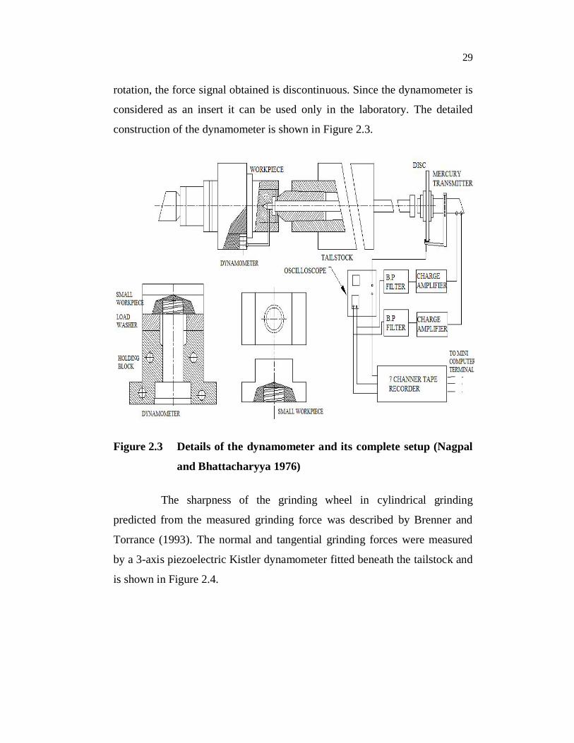
29
rotation, the force signal obtained is discontinuous. Since the dynamometer is
considered as an insert it can be used only in the laboratory. The detailed
construction of the dynamometer is shown in Figure 2.3.
Figure 2.3 Details of the dynamometer and its complete setup (Nagpal
and Bhattacharyya 1976)
The sharpness of the grinding wheel in cylindrical grinding
predicted from the measured grinding force was described by Brenner and
Torrance (1993). The normal and tangential grinding forces were measured
by a 3-axis piezoelectric Kistler dynamometer fitted beneath the tailstock and
is shown in Figure 2.4.

30
Figure 2.4 Schematic view of force measurement experimental setup (Brenner and Torrance 1993)
Drew et al (2001) investigated the variation of grinding force
with oscillating work speed. A special setup was used to support the
workpiece and mount the dynamometer in the table of cylindrical grinding.
Varghese et al (2000) developed a sensor integrated intelligent grinding wheel
for in-process monitoring. The intelligent grinding wheel consists of an
aluminium core embedded with piezoceramic sensors, fitted with diamond
abrasive segments on its periphery. The instantaneous normal grinding force
was measured using the sensors placed around the wheel core periphery.
Li et al (2002) evaluated the unsteady state grinding through the
measurement of the tangential grinding forces and normal grinding forces. A
sensor based support device made up of two hollow centers with four
electrical resistance foils pasted onto the quadrangular surface was used to
make the measuring bridge and receive signals of the grinding force. The
general view of sensor based force measurement system is shown in
Figure 2.5. The evaluation concluded that in the unsteady state grinding
process, the values of the grinding forces are much lower than those of the
steady-state grinding process and the grinding force ratio shows a non linear
fluctuation.

31
Figure 2.5 Sensor based force measurement system (Li et al 2002)
Couey et al (2005) monitored the forces generated during precision
cylindrical grinding using aerostatic spindles, where high stiffness and very
low error motions were required. The changes in the gap between the rotor
and stator with respect to the grinding force were sensed by incorporating
non-displacement sensors into an aerostatic spindle. The force resolution of
the instrumented spindle was 25 mN, which correspond to detecting a 2-nm
spindle deflection. Using the same logic, Marsh et al (2008) measured a form
error and force, Moerlein et al (2009) implemented a force measurement
based approach for controlling workpiece diameter in cylindrical grinding.
2.6 GRINDING FORCE MODEL
Modelling can quantitatively describe the relationships between
grinding parameters and helps in understanding the influence of these
parameters on grinding performances. The grinding force model describes the
correlation between input and output quantities in order to predict the
grinding force. The relative work is really extensive; still it can be subdivided
into empirical models and analytical models. The empirical models are
established through the measured data from grinding tests, in which, the

32
correlation is established between the selected input and output parameters
with a chosen model format, and then verified in further grinding tests. But
the analytical models are established based on the conformity of the process
of physical laws, using a mathematical formulation of the qualitative model.
Therefore, the analytical models rely on the understanding of the physics
behind the process and the subsequent physical models selected to describe
the mechanism. The accuracy of the models typically depends on the
assumptions and how closely the model describes the physics.
2.6.1 Analytical Model
In recent years, considerable works have been carried out to
develop a mathematical model for the grinding force, by considering the
grinding process as an interaction between the surfaces of the grinding wheel
and the workpiece, rather than a shearing action in the conventional cutting
process.
Lichun and Jizal (1980) developed a grinding force mathematical
model, which consist of two terms corresponding to chip formation forces and
frictional forces respectively. The relationship between grinding forces and
grinding kinematic process parameters with workpiece of different materials
was determined experimentally. They also analyzed the ratio between
tangential forces and normal forces with respect to both chip formation forces
and frictional forces and found that the ratio was within the range of 0.2 to
0.59.
Younis et al (1987) developed a grinding force model based on the
fact that the chip formation during grinding consists of three states:
ploughing, cutting and rubbing. Expressions for the total normal and
tangential force components during these three stages were derived. These
components were expressed in terms of the chip thickness coefficient, the

33
frictional coefficient between the grit tip area and the workpiece, the stress
coefficient arising during ploughing and, finally, the loading coefficient. The
development of mathematical models in this work particularly focused on the
variation of the geometrical form and the structure of the grinding wheel
surface resulting from loading and/or grinding wheel wear in the time
domain. It was concluded that these variations affect the rubbing component
of the main grinding force and consequently the stability of the grinding
process.
Badger and Torrance (2000) proposed two kinds of grinding force
model in surface grinding, the first model based on two-dimensional plane
strain slip-line field theory and the second based on three- dimensional
pyramid-shaped asperity model.
Hecker et al (2003) presented a 3D methodology to evaluate the
static parameters of the wheel topography and to calculate the dynamic
parameters based on a probabilistic chip thickness approach. They calculated
the dynamic grain density from the static grain density and dynamic effects
such as the kinematic shadow generated by active grains and the grain local
deflection. The normal and the tangential force per grain were calculated from
the indentation model using the hardness of the material. The dynamic grain
density and the forces per grain were used to predict the total grinding forces.
Micro-grinding with small scale grinding wheels is a micro-
machining process in precision manufacturing of miniature part features such
as those in micro sensors and micro actuators. As the diameter of grinding
wheels decreases, the negligible effects in conventional such as ploughing
forces and grinding wheel deformation become more significant in micro-
grinding. Park and Liang (2008) developed a force model for the micro
grinding process by combined consideration of mechanical and thermal
effects within a single grit interaction model at the micro-scale level of
34
material removal while the size effect of micromachining was incorporated.
In the model the forces are expressed as functions of the process
configuration, workpiece material properties and micro-grinding wheel
topography.
Hecker et al (2007) presented the predictive modelling of grinding
force and power based on the probabilistic distribution of undeformed chip
thickness as a function of the kinematic conditions, material properties, wheel
microstructure, and dynamic effects.
In most of the grinding force model deals with the average grinding
force based on a uniform grit distribution or an estimated average grit density
on the wheel without considering the random nature of the grinding force.
The random distribution of the grits on the wheel surface makes the grinding
process stochastic in nature. The random grit distribution of the rotating
wheel was described by Chang and Wang (2008) and introduced the
stochastic grit density function in the grinding force model.
Another different grinding force model by considering the chip
formation force and sliding force was proposed by Tang et al (2009). In this
model, ploughing force was neglected and the chip formation energy was
divided into static chip formation energy and dynamic chip formation energy,
mainly influenced by shear strain, shear strain rate and heat in the metal
removal process.
Most of the grinding force models neglected the effect of
ploughing, considering it to be very low in comparison with the chip
formation force. Also the coefficient of friction was taken as constant but in
reality; it varies with process parameters during the grinding process.
Durgumahanti et al (2010) developed a force model by considering the effect
35
of the input process parameters and grain size on the ploughing force
component and on the coefficient of friction.
2.6.2 Empirical Model
Normally, empirical models are used in all fields of grinding
technology due to the fact that the physical interrelationships in grinding
cannot be accurately defined. Empirical models possess simple and easy-to-
get characteristics but depend heavily on particular circumstances. The
empirical models are established by means of measured values which have
been obtained in grinding tests. The popular approach for empirical models is
to integrate expert knowledge into the process design or model system. The
expert knowledge is represented by a domain of heuristic rules which are
captured in a knowledge base. With the rapid advent of computers, expert
systems have been a substantial growth in many grinding applications. To
understand the real complexity of the grinding force, experimental
observations under different grinding conditions are necessary. In most of the
force models, grinding force is principally determined by the diameter of
grinding wheel ds, depth of cut d, work speed Vw, grinding wheel speed Vs and
contact length lc as input variables.
Liu et al (2008) developed a model of the grinding force for
aerospace alloys using an empirical approach in surface grinding. This work
pointed out that the experiment design, data processing and regression aspects
are to be concentrated on the development of empirical model.
2.7 MONITORING OF GRINDING PROCESS
A successful grinding process monitoring depends to a great extent
on reliable and robust sensors used for this purpose. In the absence of human
operators, the sensors must have the ability to recognize process

36
abnormalities and initiate corrective action. There are various signals which
correlate to the condition of the process and they are the subject of different
sensing and processing techniques. Each of these signals is able to provide a
feature related to the phenomenon of interest although at varying reliability.
So to collect the maximum amount of information about the state of a process
from a number of different sensors is the best solution.
Inasaki and Yokohama (1985) investigated the possibility of
monitoring the grinding process by using the acoustic emission (AE) signals.
The contact between the grinding wheel and the workpiece was observed to
increase the productivity by reducing non-machining time. It was monitored
by the signal of an acoustic emission (AE) sensor fixed to the tailstock center
of the workpiece and confirmed by the measured grinding wheel motor power
using a power meter.
Alfares and Elsharkawy (2000) studied the effect of dynamic
changes in the grinding force components due to changes in the grinding
wheel wear flat area and the workpiece material on the vibration behaviour of
the grinding spindle in surface grinding. Lezanski (2001) presented an
efficient way of application of neural network and fuzzy logic based systems
combining the outputs of several sensors for grinding wheel condition
monitoring during external cylindrical grinding process.
Lee and Kim (2001) investigate the external plunge grinding
process using the current signals of a spindle motor through a hall sensor. The
current signal of the spindle motor was analysed and induced a relationship
between current signals and the metal removal rate in terms of the infeed rate.
It was inferred that (i) the current value of the spindle motor decreased with
an increase of the grinding wheel speed and it increases in accordance with
the increase in not only the infeed rate but also the work speed, (ii) the current

37
signals of the spindle motor reflect the qualitative characteristics of grinding
force and the metal removal rate, and (iii) both the current signal of the
spindle motor and AE energy against material removal rate are similar.
Shih et al (2001) presented the truing and grinding forces and the
wear mechanism of particle and rod diamond blade tools were used to
generate precise and intricate forms on rotating vitreous bond silicon carbide
grinding wheels. A Hall effect sensor was used to measure the change of
grinding spindle power during truing and grinding. The truing and grinding
forces are obtained from the change of grinding wheel spindle power using
the following formula.
Tangential truing force, = (2.1)
Specific tangential grinding force, = (2.2)
where, Wt Change of spindle power in truing
Wg Change of spindle power in grinding
Vs the surface speed of grinding wheel
b the width of the grinding wheel
Kruszynski and Lajmert (2005) presented a supervision system that
uses techniques of artificial intelligence to monitor, control and optimise the
traverse grinding operation. The supervision system consists of two levels
which act in parallel to produce parts satisfying the geometrical and surface
finish requirements with maximum possible productivity. The first
optimisation level was developed to maximize the material removal rate,
simultaneously satisfying restrictions on surface roughness, out of roundness
and waviness errors. The second optimisation level considered for

38
geometrical control and is responsible for the removal of the initial shape
error by stabilising the motion trajectory of the grinding wheel in relation to
the part being produced.
Kwak et al (2006) analyzed the grinding power spent during the
process and the surface roughness of the ground workpiece in the external
cylindrical grinding of hardened SCM440 steel using the response surface
method. The grinding power was obtained by multiplying the supplied
voltage of the motor and the current measured flowing into the spindle motor
cable using a Hall effect sensor. It concluded that increasing the depth of cut
affected the grinding power more than increasing the traverse speed.
2.8 OPTIMIZATION OF MACHINING PARAMETERS
Grinding is an important finishing process for many engineering
components. An efficient application of the process and the resultant cost and
product quality depends on the quality of the process parameters used.
Although a significant amount of research has been done in the grinding, it is
difficult to make use of the results and published data in practical grinding
situations. This is because of the fact that the knowledge resource is not
consolidated, not easily available to the industrial user and often not user
friendly. As a result of this, the selection of grinding parameters still relies
very much on the input by human expert based on his personal knowledge
and experience (Midha et al 1991).
The existing analytical and experimental models have typically
been developed under a specific set of conditions in terms of workpiece
material, grinding wheel type and operation conditions, and hence are not
readily applicable to a process where operation conditions or the setup is
different than those used for the model development. Further, the difficulties
in optimization are associated with the fact that no comprehensive model

39
exist, which relate all the input variables to output process conditions
(Lee et al 2003)
Over the years, different strategies have been adopted for
optimization of grinding processes. The most common approaches use
grinding model to generate simulated outputs for the optimization, which can
be regarded as a model based optimization. Development of technologies
emerged as promising alternatives when traditional methods failed due to lack
of comprehensive mathematical models. These new technologies applied to
grinding processes, can be categorized into knowledge based expert systems,
genetic algorithm, fuzzy logic, Neural network , ant colony method, and
enumeration method.
Process parameter optimization (Mukherjee and Ray 2006) in any
machining operation can be undertaken in two stages. (i) modelling of input-
output and in-process parameter relationship, and (ii) determination of
optimal or near-optimal cutting conditions. Modelling of input-output and
in-process parameter relationship is considered as an abstract representation
of a process linking causes and effects or transforming process inputs into
outputs. The functional relationship between input-output and in-process
parameters as determined analytically for a cutting process is called
mechanistic model. However, as there is a lack of adequate and acceptable
mechanistic models for metal cutting processes, the empirical models are
generally used in metal cutting processes. Statistical regression, artificial
neural network and fuzzy set theory techniques are normally employed in the
application of modelling.

40
Figure 2.6 Classification of optimization techniques in metal cutting process (Mukherjee and Ray 2006)
Optimal or near-optimal solutions are determined by a suitable
optimization technique based on input-output and in-process parameter
relationship or objective function formulated from models with or without
constraints. The available optimization method is classified as conventional
and non-conventional optimization techniques. Classification of optimization
techniques in metal cutting process is shown in Figure 2.6.
Linear Programming (LP) based Algorithms
Conventional Techniques
Optimization Tools and Techniques
Non-conventional Techniques
Design of Experiment
Mathematical Iterative Search
Problem specific Heuristic search Meta-Heuristic
search
Dynamic Programming (DP) based Algorithms
Non-linear Programming (NLP) based Algorithms
Taguchi method based
Factorial Design based
Response Surface Design Methodology (RSM) based
Tabu Search
Genetic Algorithm Simulated Annealing

41
2.8.1 Conventional Techniques
2.8.1.1 Taguchi method
Taguchi parameter design can optimize the performance
characteristics through the setting of design parameters and reduce the
sensitivity of the system performance to sources of variation. This method is
usually appreciated for its distribution-freed and orthogonal array design, and
it provides a considerable reduction of time and resource needed to determine
important factors affecting the operations with simultaneous improvement of
quality and cost of manufacturing. Youssef et al (1994) discussed and
compared the economical benefits of Taguchi method and fractional factorial
experiments with full factorial design technique in lathe turning operations.
Yang and Tarng (1998) used the Taguchi method to optimize the cutting
parameters for turning operations. They found that cutting speed and feed rate
are the significant cutting parameters for affecting tool life and cutting speed,
feed rate and depth of cut are the significant cutting parameters for affecting
surface roughness.
Lin (2002) presented an application of Taguchi method for multi-
response optimization in face milling operation, and shows the effectiveness
of Taguchi method for simultaneous optimization and improvement of
milling performance characteristics. Shaji and Radhakrishnan (2003)
investigated the possibility of using graphite as a lubricating medium to
reduce the heat generated at the grinding zone on surface grinding using
Taguchi method and found that the process parameters such as speed, feed,
infeed and mode of dressing as influential factors on the force components
and surface finish. Also, they informed that the use of graphite produced the
lowest surface roughness at higher infeeds.

42
Manna and Bhattacharyya (2004) used Taguchi method for
determining significant cutting parameters setting to achieve better surface
finish during turning operation of aluminium and silicon carbide–based metal
matrix composite. Ghani et al (2004) applied Taguchi method in the
optimization of end milling parameters and found that the optimum
combination of low resultant cutting force and good surface finish in milling
parameters are high cutting speed, low feed rate and low depth of cut.
2.8.1.2 Response surface design methodology
Many researchers used response surface design methodology
(RSM) in metal cutting process parameter optimization problems. Lee et al
(1996) provided an interactive algorithm using both RSM and mathematical
modelling to solve a parameter optimization problem in turning operation.
The optimal machining condition for good surface finish and dimensional
accuracy as predicted using Genetic algorithm by Suresh et al (2002). A
surface roughness prediction model for turning mild steel was developed
using Response Surface Methodology (RSM). The combination of high
speed, low feed, with moderate depth of cut and nose radius produced better
surface roughness and metal removal rate and minimizes the machining time.
Kwak (2005) effectively applied Taguchi method for evaluating the
grinding parameters’ effect on a geometric error in surface grinding process
and developed a mathematical model by Response Surface Method (RSM) for
predicting the geometrical error. It was found that low levels of depth of cut
and of grain size combined with the middle levels of wheel speed and table
speed gives geometric error.
Aggarwal et al (2008) analysed the effect of cutting speed, feed
rate, depth of cut, nose radius and cutting environment on power consumption
in CNC turning of AISI p-20 tool steel. In their study, significant parameters

43
in achieving minimum power consumption were analyzed using Response
Surface Methodology (RSM) and Taguchi’s technique.
2.8.2 Non-Conventional Techniques
2.8.2.1 Genetic Algorithm
Genetic Algorithm (GA) is generally preferred for large and
complex cutting process parameter optimization problems, is based on three
basic operators, viz., reproduction, crossover, and mutation, in order to offer a
population of solutions. The algorithm creates new population from an initial
random population (obtained from different feasible combination of process
decision variables) by reproduction, crossover, and mutation in an iterative
process. The selection, crossover and mutation on initial population create a
new generation, which is evaluated with pre-defined termination criteria. The
procedure continues by considering current population as initial population
till the termination criteria are reached.
Wang et al (2002) applied GA based technique for near optimal
cutting conditions for a two and three pass turning operation having multiple
objective. Saravanan et al (2001) and (2002) developed a multi-objective
algorithm approach of the optimization of surface grinding operations using
GA. This optimization procedure was developed to optimize the grinding
conditions, viz., the wheel speed, work speed, depth of dressing and lead of
dressing, using multi-objective function model with a weighted approach for
the surface grinding process. The optimized parameter obtained using the GA
method was compared with the parameter obtained using an Ant colony
algorithm approach by Baskar et al (2004). Asokan et al (2005) used particle
swarm optimization technique.

44
Gupta et al (2001) used an enumeration method to optimize the
grinding process parameters. In this procedure, corresponding to a set of
values of input variables, a set of output parameters and a corresponding
value of objective function were obtained. From all the solution sets, the user
can select conditions which would result in better performance with respect to
the desired objective. Nandi and Banerjee (2005) proposed an intelligent
approach based on fuzzy basis functional neural network to model the
cylindrical plunge grinding process.
Gopal and Rao (2003) studied the selection of optimum conditions
for the maximum material removal rate (MRR) with surface finish and
damage as constraints in SiC grinding using Genetic Algorithm (GA). The
investigation states that the parameters, the feed rate, depth of cut and grit
size are the primary influencing factors, which affect the surface integrity of
SiC grinding.
Although GA based optimization technique works well in many
situations, a few shortcomings of this method are
i) convergence of the GA is not always assured
ii) no universal rule exists for appropriate choice of algorithm
parameter, and string length
iii) GA may require a significant execution time to attain near
optimal solutions and convergence speed of the algorithm may
be slow.
2.8.2.2 Tabu search
A local search algorithm based technique, called ‘Tabu search’
(TS), developed by Glover derives its attractiveness due to its greater
flexibility and ease of implementation in combinatorial optimization

45
problems. Kolahan and Liang (1996) explored the potentials of TS technique
for simultaneous decision making, attempt to minimize drilling cost by setting
a number of machining parameters, such as machine cutting speed, tool
travel, and tool selection for a drilling operation in a plastic mould, there is
hardly any report indicating an application of this technique for metal cutting
process parameter optimization.
2.8.2.3 Simulated Annealing
Simulated annealing (SA) technique, based on the concept of
modelling and simulation of a thermodynamic system, may be used to solve
many combinatorial process optimization problems. This technique starts
with selection of an initial random process decision vector and moves to new
neighbourhood decision vector that improves objective function value. SA
technique may accept inferior decision vector based on certain probabilistic
measure to avoid local optimal in multimodal response function. The
probability that there is a move to an inferior decision vector decreases as the
value of a ‘temperature parameter’ defined in the algorithm, decreases, which
is analogous with slow cooling in an annealing process to attain perfect
crystalline state. SA procedure of stochastic search algorithm gradually
changes to a traditional gradient descent search method as the temperature
parameter value drops. Chen and Su (1998) determined near optimal
machining conditions for a continuous profile turning operation in CNC by
using SA algorithm, and claimed that the algorithm deliver high quality
heuristic solution with reasonable computational requirements. SA is
appreciated for its simplicity and effectiveness, the convergence of the
algorithm may be strongly affected by the parameters of cooling schedule,
and no universally acceptable levels of control parameters in cooling schedule
exist for different types of cutting process parameter optimization problem.

46
Moreover, the repeatability of the near optimal solution obtained by SA with
same initial cutting conditions is not guaranteed.
2.9 MEASUREMENT OF SURFACE ROUGHNESS
Surface roughness plays an important role in many areas, and is a
factor of great importance in the evaluation of machining accuracy. Although
many factors affect the surface condition of a machined part, the machining
parameters have a significant influence on the surface roughness for a given
machine tool and workpiece set-up.
Grinding processes are often selected for the final finishing of
components because of their ability to satisfy stringent requirements of
surface roughness and tolerance. Surface roughness and tolerance are closely
interrelated, as it is generally necessary to specify a smoother finish in order
to maintain a finer tolerance in production. A close-tolerance dimension
requires a very fine finish. The finishing of a component to a very low
roughness value may require multiple machining operations. A very fine
surface finish would require grinding or additional subsequent operations,
such as honing, super finishing and buffing.
The reliability of the mechanical components, especially for high
strength applications, often critically depends upon the quality of the surface
produced by machining. This quality consists of two aspects: surface integrity
and surface topography. The surface integrity of a workpiece is associated
with the mechanical and metallurgical alterations of the surface layer induced
by machining. Surface topography refers to the geometry of machined
surfaces, which is usually characterized by surface roughness. The surface
texture refers to the micro geometry or the topography of the machined
surface.

47
Ali and Zhang (1999) presented the surface roughness prediction of
ground surface produced by surface grinding operations, using Fuzzy logic
approach. In this study they revealed that though surface roughness is one of
the most important factors in assessing the quality of a ground component,
there is no comprehensive model that can predict the surface roughness over a
wide range of operating conditions. The difficulty stems from the fact that
many variables affect the process. These include: the work material
properties, grinding wheel composition, dressing conditions, operating
parameters, coolant properties and machine vibration.
The surface roughness can be measured by a variety of instruments,
including both surface contact and non-contact types. So far, the most
universal technique is to measure the surface roughness with a contact type
stylus instrument, which provides a numerical value for surface roughness.
Such instrument provides an indication of the surface roughness in terms of
the arithmetic average, Ra.
2.10 MEASUREMENT OF SURFACE HARDNESS
Grinding is a manufacturing method imparting close dimensional
tolerance and good surface roughness. Due to very high strain rate in the
metal removal lot of heat is generated leading to increase in temperature at
the grinding zone and temperature gradient in the work material. This in turn
causes structural changes, changes in hardness distribution and generation of
tensile residual stresses in the surface layer of the workpiece. All these
changes of the surface integrity are highly disadvantageous because they lead
to a significant deterioration of tribological and fatigue properties.
Murthy et al (2000) reported that the hardness of the ground steels
are likely to drop sharply with rise in temperature beyond 4000-5000C due to
over tempering. On the other hand the austenite manganese steel gets work
48
hardened and the hardness rise sharply due to the transformation of austenite
into martensite.
Algumurthy et al (2007) analyzed the total amount of heat
generated, amount of heat entering into the workpiece, energy partition ratio,
grinding temperature, grain depth of cut, grain contact length, grit contact
time with the chip, optimization of heat generation and wheel-work contact
zone temperature for steels of different carbon composition (AISI 3310, 6150,
52100) in cylindrical grinding. Taguchi method was applied in optimizing
the heat generation and temperature developed in the grain contact zone by
considering surface roughness, surface hardness and temperature as an output
parameters. The optimization output stated that the depth of cut is the most
influencing parameter followed by the work speed, number of passes and the
wheel speed.
Hardness of the materials are measured using various test such as
abrasion test, scratch test, impact test, cutting test, rebound test etc., in which
static indentation test (Brinell, Knoop, Vickers and Rockwell) is the most
preferred test in the area of material testing. In grinding process the surface
and subsurface hardness are measured using Vickers test (Brinksmeier and
Minke 1993, Tonshoff et al 2002).
2.11 THE RESEARCH GAP
Generally, the strain gauge or piezoelectric sensor based
dynamometer are employed in the measurement of cutting forces in all
conventional metal cutting operations, including surface grinding. These
dynamometers cannot be used in cylindrical grinding, because the workpiece
and the grinding wheel are in motion. Meanwhile, some researchers have
proposed various force measurement methods for cylindrical grinding. In all
these methods, the modification has to be done in the workpiece or in the

49
machine setup. These modifications cannot be implemented in the industries
and are only suitable for research laboratory. The main objective of this
research work is to develop a measurement setup that can be implemented in
the industrial work without any major difficulty.
2.12 NEED FOR THIS STUDY
Grinding force has a direct influence on grinding wheel wear,
grinding temperature and surface quality of the workpiece. The specific
energy and the temperature generated during grinding are directly related to
the grinding forces in the form of mechanical energy. The wear mechanism of
a wheel depends on the force on an individual grain. Depending on the
magnitude of this force, wear may occur by attrition or by fracture. The
cutting force is proportional to the specific energy in grinding and this
influences the performance and surface integrity of the workpiece. Hence, the
measurement of force in grinding is very significant.
Grinding is a complicated process which involves many
parameters, such as wheel velocity, workpiece velocity, depth of cut, feed
rate, grit size, type of abrasive, wheel structure, etc. It is an important task to
select grinding parameters for achieving high grinding performance. Usually,
the desired grinding parameters and the cutting fluid are determined based on
experience or by the use of a handbook. However, this does not ensure that
the selected grinding parameters have optimal or near optimal grinding
performance for a particular machine. Hence, the quality performance in any
machine can be obtained through optimization.
2.13 SUMMARY OF LITERATURE
The summary of the literature indicates that most of the research
work is concentrated in the area of force measurement, product quality

50
analysis, tool condition monitoring, and the development of mathematical
model and optimization of machining parameters in the metal cutting
operations. Extensive studies can be found in the literature on the design and
development of the dynamometer. Most of these developments are focused on
turning, milling, drilling and surface grinding due to the inherent facility
available in the machine to accommodate the dynamometer. Due to the
difficulties in locating the dynamometer in cylindrical grinding, not much
research work has been done.
The understanding of the grinding parameters and their relation to
the responses in cylindrical grinding, are still limited and yet to be studied.
The factors that have been outlined in the literature have considered, to
explore the changes on the selected responses in cylindrical grinding.