chapter 2 – operational amplifiers
DESCRIPTION
Chapter 2 – Operational Amplifiers. Introduction. http://engr.calvin.edu/PRibeiro_WEBPAGE/courses/engr311/Handouts/OpAmp-tutorial-1.ppt Textbook CD http://www.clarkson.edu/%7Esvoboda/eta/designLab/InvertingAmplifierDesign.html. The OP-AMP Terminals. Symbol Power Supplies Exercise 2.1. _. - PowerPoint PPT PresentationTRANSCRIPT
Chapter 2 – Operational Amplifiers
Introduction
http://engr.calvin.edu/PRibeiro_WEBPAGE/courses/engr311/Handouts/OpAmp-tutorial-1.ppt
Textbook CD
http://www.clarkson.edu/%7Esvoboda/eta/designLab/InvertingAmplifierDesign.html
The OP-AMP Terminals
Symbol
Power Supplies
Exercise 2.1
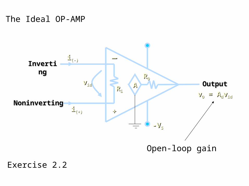
The Ideal OP-AMP
-V-VSS
vvidid
InvertingInverting
NoninvertingNoninverting
OutputOutput
++
__ii(-)(-)
ii(+)(+)
vvOO = A = Addvvidid
RROO
AARRii
Open-loop gain
Exercise 2.2
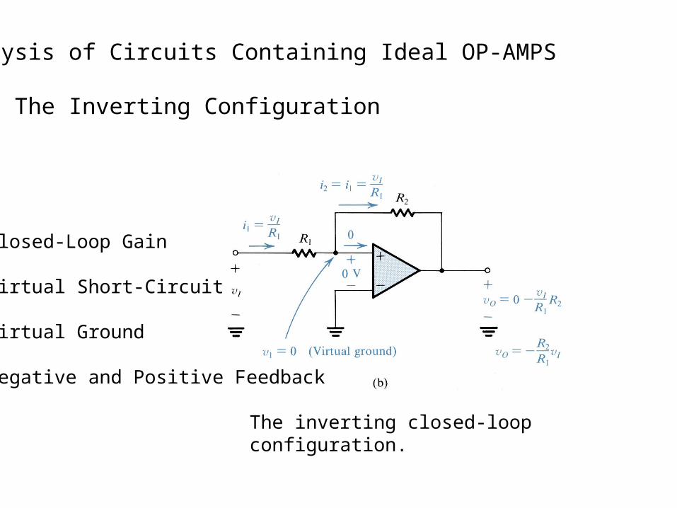
Analysis of Circuits Containing Ideal OP-AMPS
The Inverting Configuration
The inverting closed-loop configuration.
Closed-Loop Gain
Virtual Short-Circuit
Virtual Ground
Negative and Positive Feedback
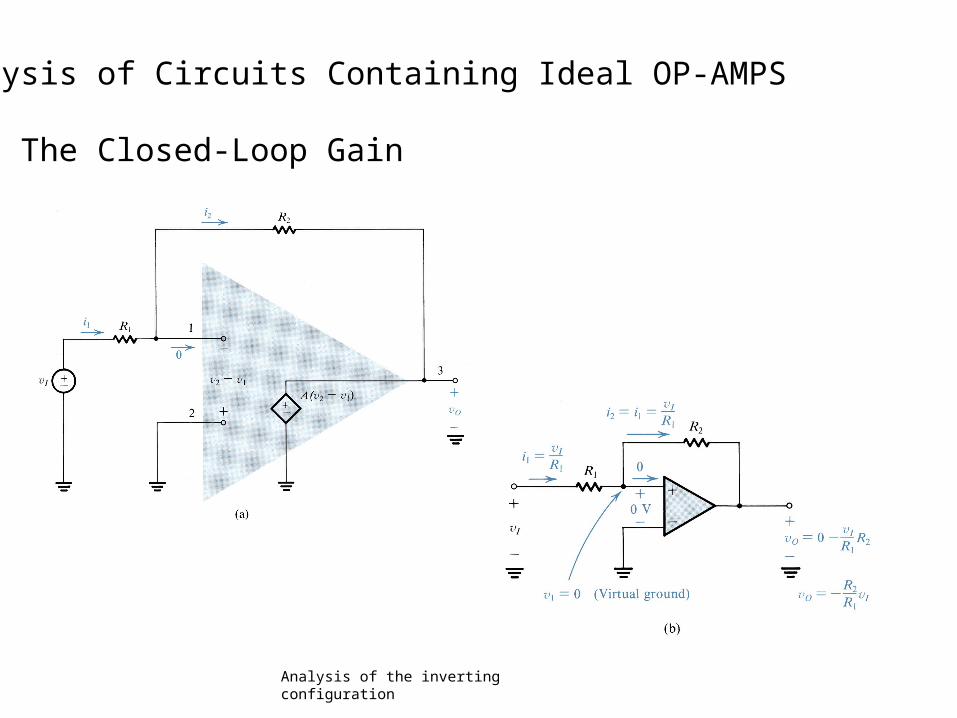
Analysis of Circuits Containing Ideal OP-AMPS
The Closed-Loop Gain
Analysis of the inverting configuration
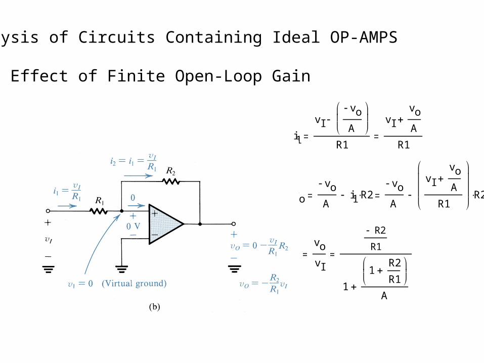
Analysis of Circuits Containing Ideal OP-AMPS
Effect of Finite Open-Loop Gain
i1
vIvo
A
R1
vIvoA
R1
vovo
Ai1 R2
vo
A
vIvoA
R1
R2
GvovI
R2
R1
11
R2R1
A

Analysis of Circuits Containing Ideal OP-AMPS
Example 2.1
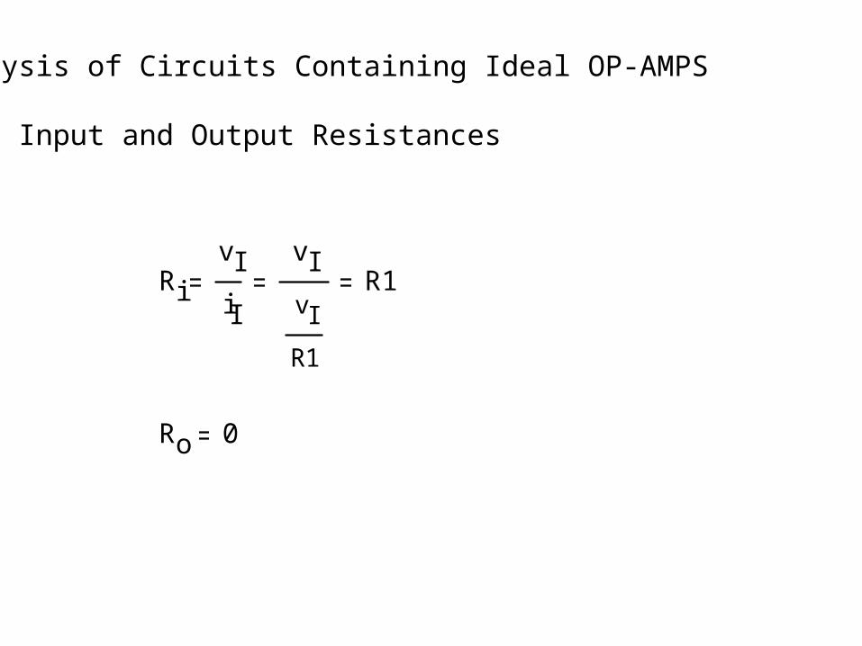
Analysis of Circuits Containing Ideal OP-AMPS
Input and Output Resistances
RivIiI
vIvI
R1
R1
Ro 0
Analysis of Circuits Containing Ideal OP-AMPS
Example 2.2

Analysis of Circuits Containing Ideal OP-AMPS
Exercises
Other Applications of the Inverting Configuration
With General Impedances
Other Applications of the Inverting Configuration
Example 2.3
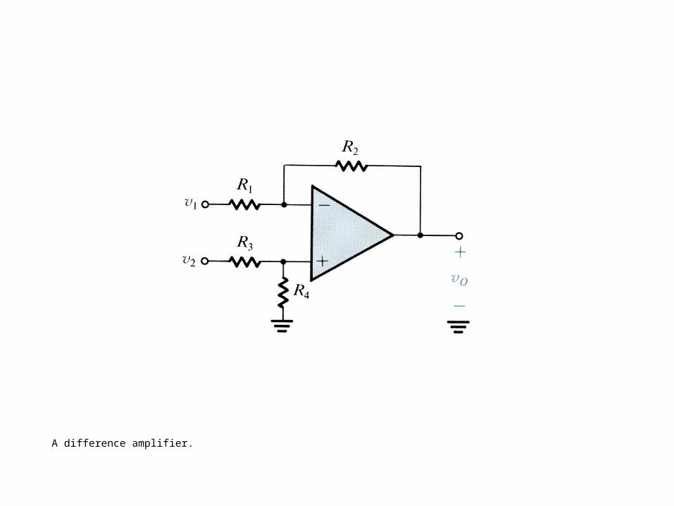
A difference amplifier.
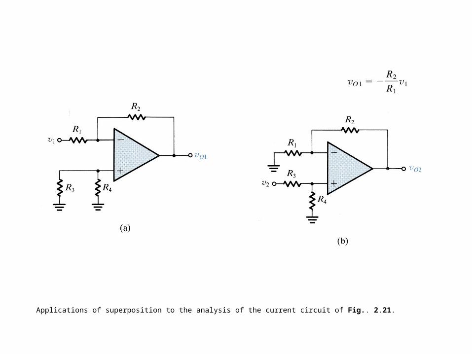
Applications of superposition to the analysis of the current circuit of Fig.. 2.21.
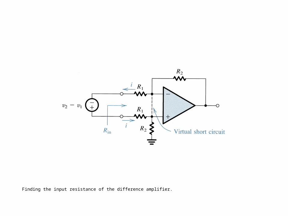
Finding the input resistance of the difference amplifier.
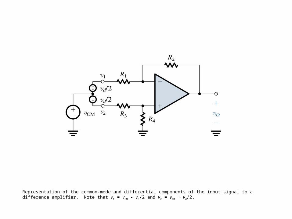
Representation of the common-mode and differential components of the input signal to a difference amplifier. Note that v1 = vCM - vd/2 and v2 = vCM + vd/2.
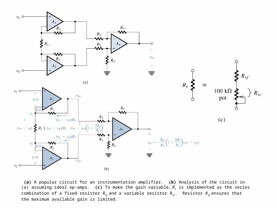
(a) A popular circuit for an instrumentation amplifier. (b) Analysis of the circuit in (a) assuming ideal op-amps. (c) To make the gain variable, R1 is implemented as the series combination of a fixed resister R1f and a variable resistor R1v. Resistor R1f ensures that the maximum available gain is limited.
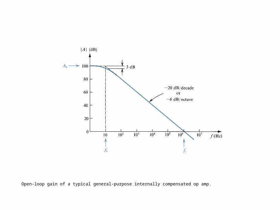
Open-loop gain of a typical general-purpose internally compensated op amp.
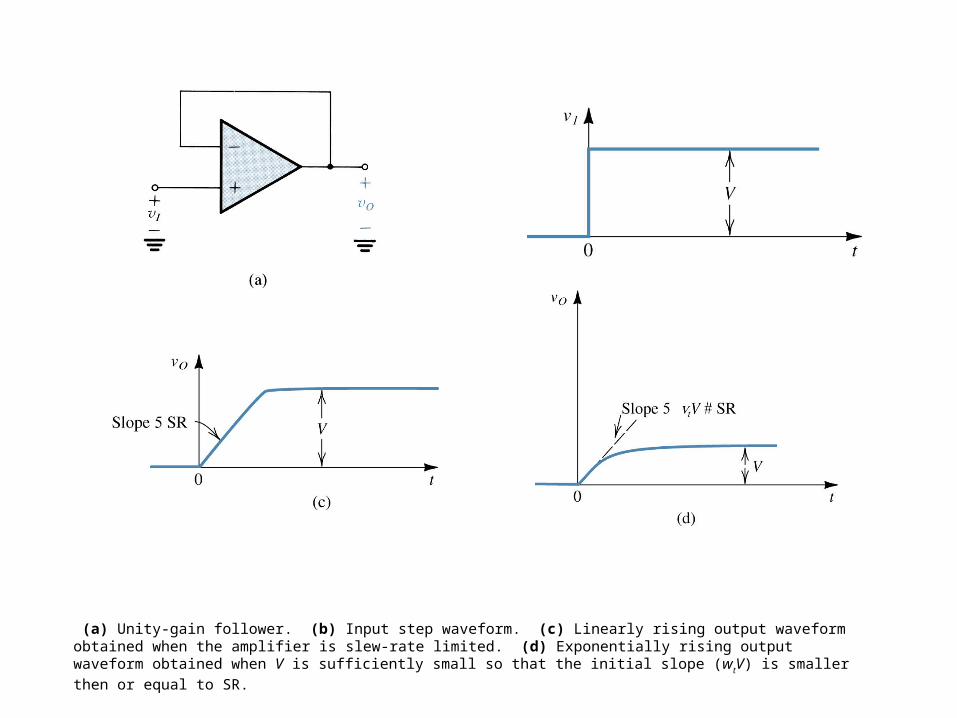
(a) Unity-gain follower. (b) Input step waveform. (c) Linearly rising output waveform obtained when the amplifier is slew-rate limited. (d) Exponentially rising output waveform obtained when V is sufficiently small so that the initial slope (wtV) is smaller then or equal to SR.
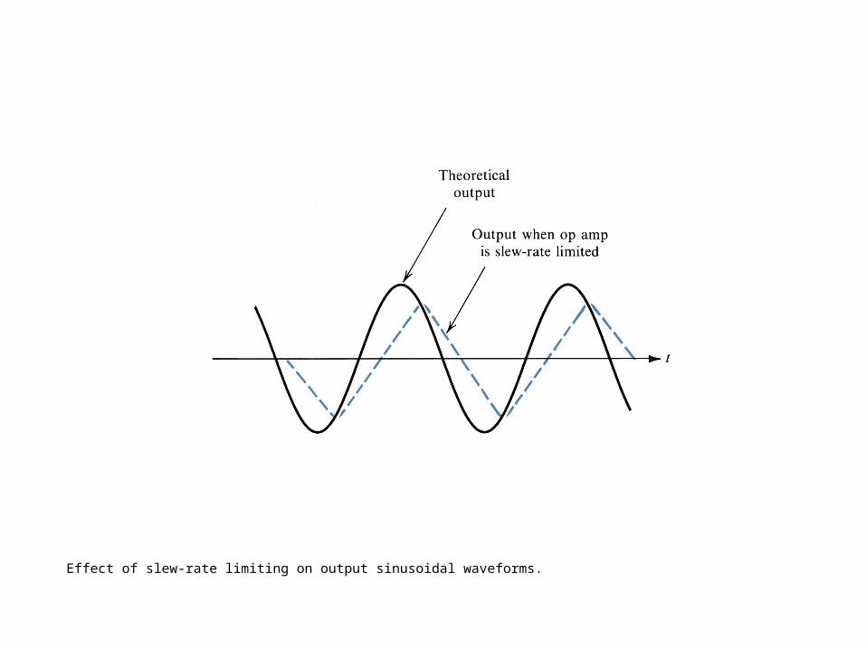
Effect of slew-rate limiting on output sinusoidal waveforms.