chapter 2 part b: engine removal and general overhaul ...totinus.free.fr/mini/autres/docs/austin mg...
TRANSCRIPT

998 cc engineOil pump:Type . . . . . . . . . . . . . . . . . . . . . . . . . . . . . . . . . . . . . . . . . . . . . . . . . . . . Bi-rotorOuter rotor endfloat . . . . . . . . . . . . . . . . . . . . . . . . . . . . . . . . . . . . . . . . 0.005 in (0.127 mm)Inner rotor endfloat . . . . . . . . . . . . . . . . . . . . . . . . . . . . . . . . . . . . . . . . . 0.005 in (0.127 mm)Outer rotor-to-body clearance . . . . . . . . . . . . . . . . . . . . . . . . . . . . . . . . 0.010 in (0.254 mm)Rotor lobe clearance . . . . . . . . . . . . . . . . . . . . . . . . . . . . . . . . . . . . . . . 0.006 in (0.152 mm)
CrankshaftMain journal diameter . . . . . . . . . . . . . . . . . . . . . . . . . . . . . . . . . . . . . . . 1.7505 to 1.7512 in (44.46 to 44.48 mm)Main bearing running clearance:
Early models . . . . . . . . . . . . . . . . . . . . . . . . . . . . . . . . . . . . . . . . . . . . 0.0007 to 0.0029 in (0.018 to 0.074 mm)1982-on . . . . . . . . . . . . . . . . . . . . . . . . . . . . . . . . . . . . . . . . . . . . . . . . 0.001 to 0.003 in (0.025 to 0.068 mm)
Main journal minimum regrind diameter . . . . . . . . . . . . . . . . . . . . . . . . . 1.7305 in (43.96 mm)Crankpin journal diameter:
Early models . . . . . . . . . . . . . . . . . . . . . . . . . . . . . . . . . . . . . . . . . . . . 1.6252 to 1.6259 in (41.28 to 41.298 mm)1982-on . . . . . . . . . . . . . . . . . . . . . . . . . . . . . . . . . . . . . . . . . . . . . . . . 0.001 to 0.0025 in (0.025 to 0.064 mm)
Crankpin running clearance . . . . . . . . . . . . . . . . . . . . . . . . . . . . . . . . . . 0.001 to 0.0027 in (0.025 to 0.069 mm)Crankpin minimum regrind diameter . . . . . . . . . . . . . . . . . . . . . . . . . . . 1.6052 in (40.77 mm)Endfloat . . . . . . . . . . . . . . . . . . . . . . . . . . . . . . . . . . . . . . . . . . . . . . . . . . 0.002 to 0.003 in (0.051 to 0.076 mm)
Connecting rodsLength between centres . . . . . . . . . . . . . . . . . . . . . . . . . . . . . . . . . . . . . 5.75 in (146.05 mm)
PistonsSkirt clearance in cylinder:
Top . . . . . . . . . . . . . . . . . . . . . . . . . . . . . . . . . . . . . . . . . . . . . . . . . . . 0.0021 to 0.0033 in (0.053 to 0.084 mm)Bottom . . . . . . . . . . . . . . . . . . . . . . . . . . . . . . . . . . . . . . . . . . . . . . . . 0.0004 to 0.0014 in (0.010 to 0.036 mm)
Oversizes available . . . . . . . . . . . . . . . . . . . . . . . . . . . . . . . . . . . . . . . . . 0.010, 0.020, 0.030, and 0.040 in (0.254, 0.508, 0.762, and 1.016 mm)
Piston ringsClearance in groove:
Top compression . . . . . . . . . . . . . . . . . . . . . . . . . . . . . . . . . . . . . . . . 0.002 to 0.0035 in (0.051 to 0.089 mm)2nd and 3rd compression . . . . . . . . . . . . . . . . . . . . . . . . . . . . . . . . . . 0.002 to 0.004 in (0.051 to 0.102 mm)
End gap:Compression . . . . . . . . . . . . . . . . . . . . . . . . . . . . . . . . . . . . . . . . . . . . 0.007 to 0.012 in (O.178 to 0.305 mm)Oil control rails . . . . . . . . . . . . . . . . . . . . . . . . . . . . . . . . . . . . . . . . . . 0.014 to 0.041 in (0.38 to 1.04 mm)
Chapter 2 Part B:Engine removal and general overhaul procedures
Ancillary components - general . . . . . . . . . . . . . . . . . . . . . . . . . . . . . .5Camshaft - removal, examination and refitting . . . . . . . . . . . . . . . . . .7Crankshaft and main bearings - removal, examination and refitting .10Cylinder block and crankcase - examination and overhaul . . . . . . . .11Cylinder head - dismantling, overhaul and reassembly . . . . . . . . . . . .6Engine - adjustment after major overhaul . . . . . . . . . . . . . . . . . . . . .12Engine - dismantling and reassembly . . . . . . . . . . . . . . . . . . . . . . . . .4
Engine/gearbox assembly - removal, examination and refitting . . . . .3Engine overhaul - general information . . . . . . . . . . . . . . . . . . . . . . . . .1Major operations only possible after removal of the engine/gearbox
from the car . . . . . . . . . . . . . . . . . . . . . . . . . . . . . . . . . . . . . . . . . . . .2Oil pump - removal, overhaul and refitting . . . . . . . . . . . . . . . . . . . . . .8Pistons and connecting rods - removal, overhaul and refitting . . . . . .9
2B•1
Easy, suitable fornovice with littleexperience
Fairly easy, suitablefor beginner withsome experience
Fairly difficult,suitable for competentDIY mechanic
Difficult, suitable forexperienced DIYmechanic
Very difficult,suitable for expertDIY or professional
Degrees of difficulty
Specifications
Contents
2B

Gudgeon pinsFit in piston . . . . . . . . . . . . . . . . . . . . . . . . . . . . . . . . . . . . . . . . . . . . . . . Hand push at 20°C (68°F)Running clearance in connecting rod . . . . . . . . . . . . . . . . . . . . . . . . . . . 0.0007 to 0.001 in (0.02 to 0.03 mm)
CamshaftJournal diameter:
Front . . . . . . . . . . . . . . . . . . . . . . . . . . . . . . . . . . . . . . . . . . . . . . . . . . 1.6655 to 1.6660 in (42.304 to 42.316 mm)Centre . . . . . . . . . . . . . . . . . . . . . . . . . . . . . . . . . . . . . . . . . . . . . . . . . 1.62275 to 1.62325 in (41.218 to 41.231 mm)Rear . . . . . . . . . . . . . . . . . . . . . . . . . . . . . . . . . . . . . . . . . . . . . . . . . . . 1.37275 to 1.3735 in (34.868 to 34.887 mm)
Running clearance in bearings . . . . . . . . . . . . . . . . . . . . . . . . . . . . . . . . 0.001 to 0.00225 in (0.025 to 0.057 mm)Endfloat . . . . . . . . . . . . . . . . . . . . . . . . . . . . . . . . . . . . . . . . . . . . . . . . . . 0.003 to 0.007 in (0.076 to 0.178 mm)Valve lift:
Inlet . . . . . . . . . . . . . . . . . . . . . . . . . . . . . . . . . . . . . . . . . . . . . . . . . . . 0.318 in (8.08 mm)Exhaust . . . . . . . . . . . . . . . . . . . . . . . . . . . . . . . . . . . . . . . . . . . . . . . . 0.300 in (7.62 mm)
Tappet outside diameter . . . . . . . . . . . . . . . . . . . . . . . . . . . . . . . . . . . . . 0.812 in (20.62 mm)
Rocker gearRocker shaft diameter . . . . . . . . . . . . . . . . . . . . . . . . . . . . . . . . . . . . . . 0.5615 to 0.5625 in (14.26 to 14.29 mm)Clearance in rockers . . . . . . . . . . . . . . . . . . . . . . . . . . . . . . . . . . . . . . . . 0.0005 to 0.0025 in (0.01 to 0.07 mm)
ValvesSeat angle . . . . . . . . . . . . . . . . . . . . . . . . . . . . . . . . . . . . . . . . . . . . . . . . 45°Head diameter:
Inlet . . . . . . . . . . . . . . . . . . . . . . . . . . . . . . . . . . . . . . . . . . . . . . . . . . . 1.093 to 1.098 in (27.76 to 27.89 mm)Exhaust . . . . . . . . . . . . . . . . . . . . . . . . . . . . . . . . . . . . . . . . . . . . . . . . 1.000 to 1.005 in (25.40 to 25.53 mm)
Stem diameter:Inlet . . . . . . . . . . . . . . . . . . . . . . . . . . . . . . . . . . . . . . . . . . . . . . . . . . . 0.2793 to 0.2798 in (7.094 to 7.107 mm)Exhaust . . . . . . . . . . . . . . . . . . . . . . . . . . . . . . . . . . . . . . . . . . . . . . . . 0.2788 to 0.2793 in (7.082 to 7.094 mm)
Clearance in guide:Inlet . . . . . . . . . . . . . . . . . . . . . . . . . . . . . . . . . . . . . . . . . . . . . . . . . . . 0.0015 to 0.0025 in (0.038 to 0.064 mm)Exhaust . . . . . . . . . . . . . . . . . . . . . . . . . . . . . . . . . . . . . . . . . . . . . . . . 0.002 to 0.003 in (0.051 to 0.076 mm)
Valve guides:Length . . . . . . . . . . . . . . . . . . . . . . . . . . . . . . . . . . . . . . . . . . . . . . . . . 1.687 in (42.85 mm)Outside diameter . . . . . . . . . . . . . . . . . . . . . . . . . . . . . . . . . . . . . . . . 0.470 to 0.471 in (11.94 to 11.96 mm)Inside diameter . . . . . . . . . . . . . . . . . . . . . . . . . . . . . . . . . . . . . . . . . . 0.2813 to 0.2818 in (7.145 to 7.158 mm)Fitted height above head:
Early model . . . . . . . . . . . . . . . . . . . . . . . . . . . . . . . . . . . . . . . . . . . 0.594 in (15.09 mm)1982-on (valves modified for inlet valve oil seals) . . . . . . . . . . . . . . 0.540 in (13.72 mm)
Valve springs:Free length . . . . . . . . . . . . . . . . . . . . . . . . . . . . . . . . . . . . . . . . . . . . . 1.95 in (49.53 mm)
Valve timing (at valve clearance of 0.021 in/0.53 mm):Inlet opens . . . . . . . . . . . . . . . . . . . . . . . . . . . . . . . . . . . . . . . . . . . . . 9° BTDCInlet closes . . . . . . . . . . . . . . . . . . . . . . . . . . . . . . . . . . . . . . . . . . . . . 41° ABDCExhaust opens . . . . . . . . . . . . . . . . . . . . . . . . . . . . . . . . . . . . . . . . . . 49° BBDCExhaust closes . . . . . . . . . . . . . . . . . . . . . . . . . . . . . . . . . . . . . . . . . . 11° ATDC
Valve clearance, inlet and exhaust (cold):Early models . . . . . . . . . . . . . . . . . . . . . . . . . . . . . . . . . . . . . . . . . . . . 0.012 in (0.30 mm)All models 1983 to 1986 (except 1983 1.0, L, HLE and City) . . . . . . . 0.012 to 0.014 in (0.30 to 0.36 mm)1983 1.0, L, HLE and City . . . . . . . . . . . . . . . . . . . . . . . . . . . . . . . . . . 0.012 in (0.30 mm)All models - 1986 on . . . . . . . . . . . . . . . . . . . . . . . . . . . . . . . . . . . . . . 0.011 to 0.013 in (0.27 to 0.33 mm)
1275 cc engine (except MG Turbo)Note: Specifications as 998 cc engine except for the following differences:
CrankshaftMain journal diameter:
Early models . . . . . . . . . . . . . . . . . . . . . . . . . . . . . . . . . . . . . . . . . . . . 2.0011 to 2.0017 in (50.83 to 50.84 mm)1986-on:
Red colour code . . . . . . . . . . . . . . . . . . . . . . . . . . . . . . . . . . . . . . . 2.0005 to 2.0009 in (50.81 to 50.82 mm)Green colour code . . . . . . . . . . . . . . . . . . . . . . . . . . . . . . . . . . . . . 2.0009 to 2.0013 in (50.82 to 50.83 mm)Yellow colour code or no colour code . . . . . . . . . . . . . . . . . . . . . . 2.0012 to 2.0017 in (50.83 to 50.84 mm)
Main bearing running clearance:Early models . . . . . . . . . . . . . . . . . . . . . . . . . . . . . . . . . . . . . . . . . . . . 0.0003 to 0.0024 in (0.008 to 0.076 mm)1986-on . . . . . . . . . . . . . . . . . . . . . . . . . . . . . . . . . . . . . . . . . . . . . . . . 0.0007 to 0.0023 in (0.017 to 0.058 mm)
Main bearing shell thickness:Yellow colour code . . . . . . . . . . . . . . . . . . . . . . . . . . . . . . . . . . . . . . . 0.0713 to 0.0717 in (1.811 to 1.821 mm)Green colour code . . . . . . . . . . . . . . . . . . . . . . . . . . . . . . . . . . . . . . . 0.0717 to 0.0721 in (1.821 to 1.831 mm)Red colour code . . . . . . . . . . . . . . . . . . . . . . . . . . . . . . . . . . . . . . . . . 0.0721 to 0.0725 in (1.831 to 1.841 mm)
2B•2 Engine removal and general overhaul procedures
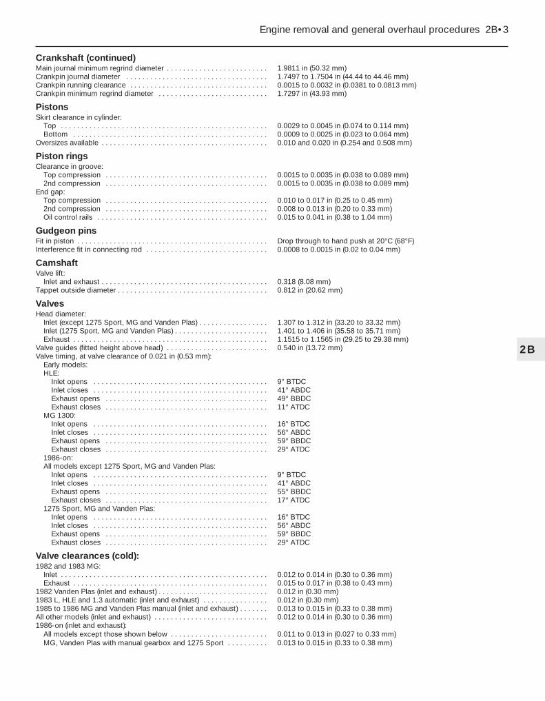
Crankshaft (continued)Main journal minimum regrind diameter . . . . . . . . . . . . . . . . . . . . . . . . . 1.9811 in (50.32 mm)Crankpin journal diameter . . . . . . . . . . . . . . . . . . . . . . . . . . . . . . . . . . . 1.7497 to 1.7504 in (44.44 to 44.46 mm)Crankpin running clearance . . . . . . . . . . . . . . . . . . . . . . . . . . . . . . . . . . 0.0015 to 0.0032 in (0.0381 to 0.0813 mm)Crankpin minimum regrind diameter . . . . . . . . . . . . . . . . . . . . . . . . . . . 1.7297 in (43.93 mm)
PistonsSkirt clearance in cylinder:
Top . . . . . . . . . . . . . . . . . . . . . . . . . . . . . . . . . . . . . . . . . . . . . . . . . . . 0.0029 to 0.0045 in (0.074 to 0.114 mm)Bottom . . . . . . . . . . . . . . . . . . . . . . . . . . . . . . . . . . . . . . . . . . . . . . . . 0.0009 to 0.0025 in (0.023 to 0.064 mm)
Oversizes available . . . . . . . . . . . . . . . . . . . . . . . . . . . . . . . . . . . . . . . . . 0.010 and 0.020 in (0.254 and 0.508 mm)
Piston ringsClearance in groove:
Top compression . . . . . . . . . . . . . . . . . . . . . . . . . . . . . . . . . . . . . . . . 0.0015 to 0.0035 in (0.038 to 0.089 mm)2nd compression . . . . . . . . . . . . . . . . . . . . . . . . . . . . . . . . . . . . . . . . 0.0015 to 0.0035 in (0.038 to 0.089 mm)
End gap:Top compression . . . . . . . . . . . . . . . . . . . . . . . . . . . . . . . . . . . . . . . . 0.010 to 0.017 in (0.25 to 0.45 mm)2nd compression . . . . . . . . . . . . . . . . . . . . . . . . . . . . . . . . . . . . . . . . 0.008 to 0.013 in (0.20 to 0.33 mm)Oil control rails . . . . . . . . . . . . . . . . . . . . . . . . . . . . . . . . . . . . . . . . . . 0.015 to 0.041 in (0.38 to 1.04 mm)
Gudgeon pinsFit in piston . . . . . . . . . . . . . . . . . . . . . . . . . . . . . . . . . . . . . . . . . . . . . . . Drop through to hand push at 20°C (68°F)Interference fit in connecting rod . . . . . . . . . . . . . . . . . . . . . . . . . . . . . . 0.0008 to 0.0015 in (0.02 to 0.04 mm)
CamshaftValve lift:
Inlet and exhaust . . . . . . . . . . . . . . . . . . . . . . . . . . . . . . . . . . . . . . . . . 0.318 (8.08 mm)Tappet outside diameter . . . . . . . . . . . . . . . . . . . . . . . . . . . . . . . . . . . . . 0.812 in (20.62 mm)
ValvesHead diameter:
Inlet (except 1275 Sport, MG and Vanden Plas) . . . . . . . . . . . . . . . . . 1.307 to 1.312 in (33.20 to 33.32 mm)Inlet (1275 Sport, MG and Vanden Plas) . . . . . . . . . . . . . . . . . . . . . . . 1.401 to 1.406 in (35.58 to 35.71 mm)Exhaust . . . . . . . . . . . . . . . . . . . . . . . . . . . . . . . . . . . . . . . . . . . . . . . . 1.1515 to 1.1565 in (29.25 to 29.38 mm)
Valve guides (fitted height above head) . . . . . . . . . . . . . . . . . . . . . . . . . 0.540 in (13.72 mm)Valve timing, at valve clearance of 0.021 in (0.53 mm):
Early models:HLE:
Inlet opens . . . . . . . . . . . . . . . . . . . . . . . . . . . . . . . . . . . . . . . . . . . 9° BTDCInlet closes . . . . . . . . . . . . . . . . . . . . . . . . . . . . . . . . . . . . . . . . . . . 41° ABDCExhaust opens . . . . . . . . . . . . . . . . . . . . . . . . . . . . . . . . . . . . . . . . 49° BBDCExhaust closes . . . . . . . . . . . . . . . . . . . . . . . . . . . . . . . . . . . . . . . . 11° ATDC
MG 1300:Inlet opens . . . . . . . . . . . . . . . . . . . . . . . . . . . . . . . . . . . . . . . . . . . 16° BTDCInlet closes . . . . . . . . . . . . . . . . . . . . . . . . . . . . . . . . . . . . . . . . . . . 56° ABDCExhaust opens . . . . . . . . . . . . . . . . . . . . . . . . . . . . . . . . . . . . . . . . 59° BBDCExhaust closes . . . . . . . . . . . . . . . . . . . . . . . . . . . . . . . . . . . . . . . . 29° ATDC
1986-on:All models except 1275 Sport, MG and Vanden Plas:
Inlet opens . . . . . . . . . . . . . . . . . . . . . . . . . . . . . . . . . . . . . . . . . . . 9° BTDCInlet closes . . . . . . . . . . . . . . . . . . . . . . . . . . . . . . . . . . . . . . . . . . . 41° ABDCExhaust opens . . . . . . . . . . . . . . . . . . . . . . . . . . . . . . . . . . . . . . . . 55° BBDCExhaust closes . . . . . . . . . . . . . . . . . . . . . . . . . . . . . . . . . . . . . . . . 17° ATDC
1275 Sport, MG and Vanden Plas:Inlet opens . . . . . . . . . . . . . . . . . . . . . . . . . . . . . . . . . . . . . . . . . . . 16° BTDCInlet closes . . . . . . . . . . . . . . . . . . . . . . . . . . . . . . . . . . . . . . . . . . . 56° ABDCExhaust opens . . . . . . . . . . . . . . . . . . . . . . . . . . . . . . . . . . . . . . . . 59° BBDCExhaust closes . . . . . . . . . . . . . . . . . . . . . . . . . . . . . . . . . . . . . . . . 29° ATDC
Valve clearances (cold):1982 and 1983 MG:
Inlet . . . . . . . . . . . . . . . . . . . . . . . . . . . . . . . . . . . . . . . . . . . . . . . . . . . 0.012 to 0.014 in (0.30 to 0.36 mm)Exhaust . . . . . . . . . . . . . . . . . . . . . . . . . . . . . . . . . . . . . . . . . . . . . . . . 0.015 to 0.017 in (0.38 to 0.43 mm)
1982 Vanden Plas (inlet and exhaust) . . . . . . . . . . . . . . . . . . . . . . . . . . . 0.012 in (0.30 mm)1983 L, HLE and 1.3 automatic (inlet and exhaust) . . . . . . . . . . . . . . . . 0.012 in (0.30 mm)1985 to 1986 MG and Vanden Plas manual (inlet and exhaust) . . . . . . . 0.013 to 0.015 in (0.33 to 0.38 mm)All other models (inlet and exhaust) . . . . . . . . . . . . . . . . . . . . . . . . . . . . 0.012 to 0.014 in (0.30 to 0.36 mm)1986-on (inlet and exhaust):
All models except those shown below . . . . . . . . . . . . . . . . . . . . . . . . 0.011 to 0.013 in (0.027 to 0.33 mm)MG, Vanden Plas with manual gearbox and 1275 Sport . . . . . . . . . . 0.013 to 0.015 in (0.33 to 0.38 mm)
Engine removal and general overhaul procedures 2B•3
2B

Note: An engine which has had regular andfrequent oil and filter changes, as well as otherrequired maintenance, should give manythousands of miles of reliable service. Beforebeginning the engine overhaul, read throughthe entire procedure, to familiarise yourselfwith the scope and requirements of the job.
GeneralIt is not always easy to determine when, or
if, an engine should be completelyoverhauled, as a number of factors must beconsidered.
High mileage is not necessarily anindication that an overhaul is needed, whilelow mileage does not preclude the need for anoverhaul. Frequency of servicing is probablythe most important consideration. An enginewhich has had regular and frequent oil andfilter changes, as well as other requiredmaintenance, should give many thousands ofmiles of reliable service. Conversely, aneglected engine may require an overhaulvery early in its life.
Excessive oil consumption is an indicationthat piston rings, valve seals and/or valveguides are in need of attention. Make surethat oil leaks are not responsible beforedeciding that the rings and/or guides areworn.
Check the oil pressure with a gauge fitted inplace of the oil pressure switch, and compareit with that specified. If it is extremely low, themain and big-end bearings, and/or the oilpump, are probably worn out.
Loss of power, rough running, knocking ormetallic engine noises, excessive valve gearnoise, and high fuel consumption may alsopoint to the need for an overhaul, especially ifthey are all present at the same time. If a
complete service does not remedy thesituation, major mechanical work is the onlysolution.
An engine overhaul involves restoring allinternal parts to the specification of a newengine. During an overhaul, the cylinders arerebored (where necessary) and the pistonsand the piston rings are renewed. New mainand big-end bearings are generally fitted; ifnecessary, the crankshaft may be renewed orreground, to restore the journals. The valvesare also serviced as well, since they areusually in less-than-perfect condition at thispoint. While the engine is being overhauled,other components, such as the distributor(where applicable), starter and alternator, canbe overhauled as well. The end result shouldbe an as-new engine that will give manytrouble-free miles.
Critical cooling system components suchas the hoses, thermostat and water pumpshould be renewed when an engine isoverhauled. The radiator should be checkedcarefully, to ensure that it is not clogged orleaking. Also, it is a good idea to renew the oilpump whenever the engine is overhauled.
Before beginning the engine overhaul, readthrough the entire procedure, to familiariseyourself with the scope and requirements ofthe job. Overhauling an engine is not difficult ifyou follow carefully all of the instructions,have the necessary tools and equipment, andpay close attention to all specifications. It can,however, be time-consuming. Plan on the carbeing off the road for a minimum of twoweeks, especially if parts must be taken to anengineering works for repair or reconditioning.Check on the availability of parts, and makesure that any necessary special tools andequipment are obtained in advance. Mostwork can be done with typical hand tools,although a number of precision measuringtools are required for inspecting parts todetermine if they must be renewed. Often the
engineering works will handle the inspectionof parts, and will offer advice concerningreconditioning and renewal.
Always wait until the engine has beencompletely dismantled, and until allcomponents (especially the cylinderblock/crankcase and the crankshaft) havebeen inspected, before deciding what serviceand repair operations must be performed byan engineering works. The condition of thesecomponents will be the major factor toconsider when determining whether tooverhaul the original engine, or to buy areconditioned unit. Do not, therefore,purchase parts or have overhaul work doneon other components until they have beenthoroughly inspected. As a general rule, timeis the primary cost of an overhaul, so it doesnot pay to fit worn or sub-standard parts.
As a final note, to ensure maximum life andminimum trouble from a reconditioned engine,everything must be assembled with care, in aspotlessly-clean environment.
Note: The engine and gearbox assembly mustbe lifted from the car as a complete unit, thenthe engine separated from the gearbox on thebench.
The following operations can only becarried out after removal of the engine andgearbox from the car:a) Removal of the camshaft.b) Removal of the oil pump.c) Removal of the piston/connecting rod
assemblies.d) Renewal of the crankshaft main bearings
and big-end bearings.e) Removal of the tappets (cam followers) on
the 1275 cc engine only.
2 Major operations only possibleafter removal of the engine/gearbox from the car
1 Engine overhaul - generalinformation
1275 cc engine (MG Turbo)Valve clearances (cold):1982 and 1983:
Inlet . . . . . . . . . . . . . . . . . . . . . . . . . . . . . . . . . . . . . . . . . . . . . . . . . . . 0.014 in (0.35 mm)Exhaust . . . . . . . . . . . . . . . . . . . . . . . . . . . . . . . . . . . . . . . . . . . . . . . . 0.016 in (0.40 mm)
1984-on:Inlet . . . . . . . . . . . . . . . . . . . . . . . . . . . . . . . . . . . . . . . . . . . . . . . . . . . 0.012 to 0.014 in (0.30 to 0.35 mm)Exhaust . . . . . . . . . . . . . . . . . . . . . . . . . . . . . . . . . . . . . . . . . . . . . . . . 0.014 to 0.016 in (0.35 to 0.40 mm)
ValvesStem diameter:
Exhaust . . . . . . . . . . . . . . . . . . . . . . . . . . . . . . . . . . . . . . . . . . . . . . . . 0.3131 to 0.3137 in (7.955 to 7.970 mm)Clearance in guide:
Exhaust . . . . . . . . . . . . . . . . . . . . . . . . . . . . . . . . . . . . . . . . . . . . . . . . 0.0031 to 0.0032 in (0.079 to 0.081 mm)Valve guides:
Inside diameter (reamed) - exhaust . . . . . . . . . . . . . . . . . . . . . . . . . . 0.3164 to 0.3169 in (8.036 to 8.049 mm)Valve springs free length:
Inner . . . . . . . . . . . . . . . . . . . . . . . . . . . . . . . . . . . . . . . . . . . . . . . . . . 1.703 in (43.256 mm)Outer . . . . . . . . . . . . . . . . . . . . . . . . . . . . . . . . . . . . . . . . . . . . . . . . . . 1.740 in (44196 mm)
2B•4 Engine removal and general overhaul procedures

Removal1 Remove the bonnet (refer to Chapter 11, ifnecessary) and place it securely to one side.2 Disconnect the battery negative thenpositive leads, and remove the battery asdescribed in Chapter 5.3 Remove the solenoid and place it to oneside, then unbolt and remove the batterycarrier (see illustration).4 Drain the cooling system (Chapter 3).5 Unscrew the drain plug and drain theengine/gearbox oil into a container. Refit thedrain plug.6 Remove the radiator (Chapter 3).7 Unbolt and remove the crossmember stay.Disconnect the bonnet lock cable and removethe crossmember.8 Remove the air cleaner (Chapter 4).9 Disconnect the exhaust system from themanifold with reference to Chapter 4.10 Unbolt the engine earth lead from theflywheel housing (see illustration). Disconnectand remove the starter supply lead.11 Disconnect and remove the hose from thewater pump, expansion tank, and heater.12 Disconnect the expansion tank vent pipeand heater hose from the thermostat housing.13 Disconnect and plug the fuel supply hosefrom the fuel pump.14 Where fitted, disconnect the brake servovacuum hose from the inlet manifold.15 Remove the clutch slave cylinder (ifapplicable), as described in Chapter 6, butleave it attached to the hydraulic hose.16 Identify then disconnect the wiring fromthe coil low tension terminals, alternator,water temperature sender unit, and oilpressure switch.17 Remove the cross-head screws andwithdraw the air cleaner elbow from thecarburettor. Remove the gasket.18 Unscrew the speedometer cable from thegearbox and place it to one side.19 Disconnect the choke and throttle cablesfrom the carburettor (Chapter 4).20 Turn the steering as necessary to allow
access from the front, and remove therebound buffers from the subframe on bothsides. The buffers are located beneath thesuspension upper arms and are secured bytwo cross-head screws.21 Insert distance pieces such as suitablysized nuts in place of the buffers to retain thesuspension in the normal running position.22 Apply the handbrake, jack up the front ofthe car, and support it on axle stands (see“Jacking and vehicle support”).23 On manual gearbox models, drive out theroll pin and disconnect the gear selector rodfrom the selector shaft. Unbolt the steady rodfrom the gearbox.24 On automatic transmission models,unbolt the bellcrank cover plate from theright-hand side of the gearbox and disconnectthe selector cable (refer to Chapter 7B ifnecessary). Disconnect the pipes from the oilcooler.25 On all models where fitted, unbolt theexhaust downpipe bracket from the gearbox.
26 The driveshaft inner joints must now bereleased from the spring rings on thedifferential side gears. To do this use twolevers but take care not to damage thedifferential side covers. If difficulty isexperienced, rotate the front wheel slightly toa different position. Once released, the innerjoints can be prevented from engaging thespring rings again by wrapping a length ofthick wire or plastic tubing around thedriveshaft.27 Attach a hoist to the engine/gearbox unit;two brackets fitted to the valve cover nutsmay be used for lifting (see illustration). Takethe weight of the unit.28 Unscrew and remove the engine frontmounting bolts, and remove the spacers,noting their location. Note that during 1982,the four point engine mounting system wasreplaced with a three point system, as shown(see illustrations).29 Unscrew and remove the engine rearmounting nuts, right-hand side from the top
3 Engine/gearbox assembly -removal, examination andrefitting
Engine removal and general overhaul procedures 2B•5
2B
3.27 Suitable engine lifting bracket3.10 Engine earth lead location3.3 Removing the solenoid
3.28a Four-point engine mountingcomponents (early models)
1 Right-hand rear bracket2 Right-hand rear mounting3 Right-hand front bracket
stiffener4 Right-hand front bracket5 Left-hand rear mounting6 Left-hand rear bracket7 Buffer plate8 Right-hand front mounting9 Left-hand front bracket10 Left-hand front mounting

and left-hand side from underneath (seeillustrations).30 Raise the engine/gearbox unit from theengine compartment and at the same timelever the driveshaft inner joints from the
differential side gears. Make sure that all wires,cables, and hoses have been disconnected,and take care not to damage any componentmounted on the bulkhead or enginecompartment panels (see illustrations).
31 Lower the units onto a workbench or alarge piece of wood placed on the floor.32 Refer to Chapters 7A and 7B forseparation of the gearbox/transmission.
2B•6 Engine removal and general overhaul procedures
3.28c Left-hand engine mounting (from above)
3.30a Removing the engine/gearbox3.29c Left-hand rear engine mounting(from below)
3.29b Right-hand rear engine mounting(from below)
3.29a Right-hand rear engine mounting(from above) - engine removed
3.28f Right-hand rear engine mountingfitted to MG Turbo models
1 Subframe bracket2 Mounting rubber
3 Snubber4 Engine bracket
3.28e Right-hand front engine mounting(from below)
3.28d Left-hand front engine mounting(from below)
3.28b Three-point enginemountings. Manual transmission
version shown - automatic issimilar

Examination33 With the engine completely stripped,clean all the components and examine themfor wear. Each part should be checked, andwhere necessary renewed or renovated asdescribed in the following Sections. Renewmain and big-end shell bearings as a matter ofcourse, unless you know that they have hadlittle wear and are in perfect condition.
Refitting34 Refitting is a reversal of the removalprocedure, but note the following additionalpoints:a) Insert the left-hand side driveshaft into the
differential unit first, then twist the engineand insert the right-hand side driveshaft.
b) Adjust the choke and throttle cables(Chapter 4).
c) Refill the engine/gearbox with oil.d) Refill the cooling system (Chapter 3).e) On automatic transmission models adjust
the selector cable (Chapter 7B).
Dismantling1 If possible, mount the engine on a stand forthe dismantling procedure, but failing this,support it in an upright position with blocks ofwood placed under each side of thecrankcase.2 Cleanliness is most important, and if theengine is dirty, it should be cleaned withparaffin while keeping it in an upright position.3 Avoid working with the engine directly on aconcrete floor, as grit presents a real sourceof trouble.4 As parts are removed, clean them in aparaffin bath. However, do not immerse partswith internal oilways in paraffin as it is difficultto remove, usually requiring a high pressurehose. Clean oilways with nylon pipe cleaners.5 It is advisable to have containers to holdsmall items according to their use, as this willhelp when reassembling the engine and alsoprevent possible losses.6 Always obtain complete sets of gasketswhen the engine is being dismantled, butretain the old gaskets with a view to using
them as a pattern to make a replacement if anew one is not available.7 When possible, refit nuts, bolts, andwashers in their location after being removed,as this helps to protect the threads and willalso be helpful when reassembling the engine.8 Retain unserviceable components in orderto compare them with the new parts supplied.
Reassembly9 The following sections deal with examiningand replacing the various components,however note the following.10 To ensure maximum life with minimumtrouble from a rebuilt engine, not only musteverything be correctly assembled, but it mustalso be spotlessly clean. All oilways must beclear, and locking washers and springwashers must be fitted where indicated. Oil allbearings and other working surfacesthoroughly with engine oil during assembly.11 Before assembly begins, renew any boltsor studs with damaged threads.12 Gather together a torque wrench, oil can,clean rag, and a set of engine gaskets and oilseals, together with a new oil filter cartridge.
General1 With the engine separated from thegearbox, the externally mounted ancillarycomponents can be removed. For furtherdetails on these items refer to the appropriateChapter.
a) Inlet and exhaust manifold andcarburettor (Chapter 4).
b) Fuel pump (Chapter 4).c) Alternator (Chapter 5).d) HT leads and spark plugs (Chapter 5).e) Oil filter (Chapter 1).f) Rear engine mountings and brackets (see
illustration).g) Distributor (Chapter 5).h) Dipstick.i) Oil pressure switch (see illustration) and
water temperature switch.j) Water pump (Chapter 3).k) Thermostat (Chapter 3).
Note: For details on the cylinder head removaland refitting, refer to Chapter 2A.
Dismantling1 Using a valve spring compressor, compresseach valve spring in turn until the split colletscan be removed (see illustration). Releasethe compressor and remove the cup andspring. If the cups are difficult to release, donot continue to tighten the compressor, butgently tap the top of the tool with a hammer.Always make sure that the compressor is heldfirmly over the cup.2 On the 1275 cc engine remove the oil sealsfrom the inlet valve guides (see illustration).A small seal may also be fitted at the bottomof the collet groove on the valve stems.
6 Cylinder head - dismantling,overhaul and reassembly
5 Ancillary components - general
4 Engine - dismantling andreassembly
Engine removal and general overhaul procedures 2B•7
2B
5.1b Oil pressure switch
6.2 Removing an inlet valve guide oil seal(1275 cc engine)
6.1 Removing the valve split collets
5.1a Left-hand rear engine mounting3.30b Engine compartment withengine/gearbox removed

3 Remove each valve from the combustionchambers keeping them in their order ofremoval, together with the respective valvesprings and cups (see illustrations). Identifyeach valve according to the cylinder,remembering that No 1 cylinder is at thethermostat end of the cylinder head.
Overhaul4 The operation will normally only be requiredat comparatively high mileage. However, ifpersistent pinking occurs and performancehas deteriorated even though the engineadjustments are correct, decarbonising andvalve grinding may be required.5 With the cylinder head removed, use ascraper to remove the carbon from thecombustion chambers and ports. Remove alltraces of gasket from the cylinder headsurface, then wash it thoroughly with paraffin.6 Use a straight edge and feeler blade tocheck that the cylinder head surface is notdistorted. If it is, it must be resurfaced by asuitably equipped engineering works.7 If the engine is still in the car, clean thepiston crowns and cylinder bore upper edges,but make sure that no carbon drops betweenthe pistons and bores. To do this, locate twoof the pistons at the top of their bores andseal off the remaining bores with paper andmasking tape. Press a little grease betweenthe two pistons and their bores to collect anycarbon dust; this can be wiped away whenthe piston is lowered. To prevent carbonbuild-up, polish the piston crown with metalpolish, but remove all traces of the polishafterwards.8 Examine the heads of the valves for pittingand burning, especially the exhaust valveheads. Renew any valve which is badly burnt.Examine the valve seats at the same time. Ifthe pitting is very slight, it can be removed bygrinding the valve heads and seats togetherwith coarse, then fine, grinding paste.9 Where excessive pitting has occurred, thevalve seats must be recut or renewed by asuitably equipped engineering works.10 Valve grinding is carried out as follows.Place the cylinder head upside down on abench with a block of wood at each end togive clearance for the valve stems.
11 Smear a trace of coarse carborundumpaste on the seat face and press a suctiongrinding tool onto the valve head. With asemi-rotary action, grind the valve head to itsseat, lifting the valve occasionally toredistribute the grinding paste. When a dullmatt even surface is produced on both thevalve seat and the valve, wipe off the pasteand repeat the process with fine carborundumpaste as before. A light spring placed underthe valve head will greatly ease this operation.When a smooth unbroken ring of light greymatt finish is produced on both the valve andseat, the grinding operation is complete.12 Scrape away all carbon from the valvehead and stem, and clean away all traces ofgrinding compound. Clean the valves andseats with a paraffin soaked rag, then wipewith a clean rag.13 If the valve guides are worn, indicated bya side-to-side motion of the valve, new guidesmust be fitted. To do this, use a mandrel topress the worn guides downwards and outthrough the combustion chamber. Press thenew guides into the cylinder head in the samedirection until they are at the specified fittedheight (see illustration).14 If the original valve springs have been inuse for 20 000 miles (32 000 km) or more,renew them. Where fitted, the inlet valve oilseals should also be renewed whenever thecylinder head is dismantled.15 Examine the pushrods and rocker shaftassembly for wear and renew them asnecessary. Dismantling and reassembly of therocker components is straightforward (seeillustration).
Reassembly16 The valve stem oil seals fitted to the largerengine, are now fitted to the smaller engine aswell. This has the effect of reducing oilconsumption.17 The fitting of the seals has also requiredthe fitting of modified valves (with cottergrooves nearer the end of the stem). The valvespring seat has also been raised by 0.05 in(1.2 mm).18 New type valves and seals can be fitted toold type cylinder heads, in complete sets only,with the addition of a shim 0.05 in (1.2 mm)thick underneath each spring. These shimsmay also be found already fitted to engineswhich left the factory with new type valvesand seals in unmodified heads.19 Fit the valves in their original sequence or,if new valves have been obtained, to the seatto which they have been ground.20 Oil the valve stems liberally and, onthe 1275 cc engine, fit the oil seals to the inletvalve guides and collet grooves whereapplicable.21 Working on one valve, fit the spring andcup, then compress the spring with thecompressor and insert the split collets.Release the compressor and remove it. 22 Repeat the procedure on the remainingvalves. Tap the end of each valve stem with anon-metallic mallet to settle the collets.
Removal1 Remove the engine and gearbox asdescribed in Section 3. It is not necessary toseparate the engine from the gearbox, unlessthe tappets are to be removed on the 1275 ccengine.2 Remove the rocker cover, rocker shaft, andpushrods.3 On the 998 cc engine, remove the tappetsas described in Chapter 2A.4 On both the 998 cc and 1275 cc engines,remove the distributor (Chapter 5) and the fuelpump (Chapter 4).5 Using a 5⁄16 in bolt, remove the distributor
7 Camshaft - removal,examination and refitting
2B•8 Engine removal and general overhaul procedures
6.3a Removing an inlet valve
6.13 Valve guide fitted height dimension“A”
Arrow indicates direction of removal andrefitting
6.15 Rocker shaft components
6.3b Valve components

driveshaft from the cylinder block (seeillustration).6 Remove the timing cover, chain, and gearsas described in Chapter 2A.7 On the 1275cc engine, invert the engine sothat the tappets are clear of the camshaft.8 Unbolt the camshaft locating plate from theengine front plate (see illustration).9 Withdraw the camshaft from the timingchain end of the cylinder block, taking carenot to damage the three camshaft bearings asthe lobes of the cams pass through them (seeillustration).10 If the 1275 cc engine is separated fromthe gearbox, remove the tappets keepingthem identified for location (see illustration).If the 1275 cc engine is not separated fromthe gearbox, do not place it upright otherwisethe tappets will fall into the gearbox.
Examination11 Examine the camshaft bearing surfaces,cam lobes, and skew gear for wear. Ifexcessive, renew the shaft.12 Check the locating plate for wear andrenew it if necessary.13 Check the camshaft bearings for wearand if necessary remove them with a length oftubing. Fit the new prefinished bearings withtheir oil holes aligned with the oilways in thecylinder block.14 Examine the tappets for wear and renewthem if necessary.
Refitting15 If the 1275 cc engine is separated fromthe gearbox, lubricate the tappets with engineoil and insert them in their original locationswith the engine inverted.16 Oil the camshaft bearings and carefullyinsert the camshaft from the timing chain endof the cylinder block. Make sure that the oilpump spindle engages the slot in thecamshaft.17 Fit the locating plate to the front plate andtighten the bolts evenly. 18 Temporarily refit the camshaft sprocketthen, using a dial gauge, vernier calipers, orfeeler blade and bridging piece, check thatthe camshaft endfloat is within the specifiedlimits. If not, renew the locating plate.19 With the engine upright, refit the timingcover, chain, and gears as described inChapter 2A.20 Turn the engine until No 1 piston is at top
dead centre (TDC) on the compression stroke.If the cylinder head is not yet fitted, use twopushrods to determine the point when No 4cylinder valves are rocking - in this positionNo 1 piston is at TDC compression.21 Using the 5⁄16 in bolt, insert the distributordriveshaft into the cylinder block with thelarger segment uppermost, and the slot in the4 o’clock position. As the driveshaft engagesthe skew gear on the camshaft, it will turnanti-clockwise to the 2 o’clock position.Remove the bolt (see illustrations).22 Refit the distributor (Chapter 5) and thefuel pump (Chapter 4).23 On the 998 cc engine refit the tappets asdescribed in Chapter 2A. 24 Refit the pushrods and rocker shaft andadjust the tappets as described in Chapter 2A.Refit the rocker cover.25 Refit the engine and gearbox as describedin Section 3.
Removal1 Remove the engine and gearbox asdescribed in Section 3.2 Remove the flywheel/torque converterhousing with reference to Chapters 7A and 7B.3 On automatic transmission models only,remove the oil feed pipe from the oil pump.
8 Oil pump - removal, overhauland refitting
Engine removal and general overhaul procedures 2B•9
2B
7.9 Removing the camshaft on the 1275 ccengine (crankshaft removed for clarity)
7.21c Installed position of the distributordriveshaft
7.21b Distributor driveshaft fittingprocedure for 1985-on 1.3 models
1 Initial fitting position 2 Fitted position (TDC)
7.21a Distributor driveshaft fittingprocedure
1 Initial fitting position 2 Fitted position
7.10 Removing the tappets (1275 cc engine)
7.8 Removing the camshaft locating plate7.5 Removing the distributor driveshaft
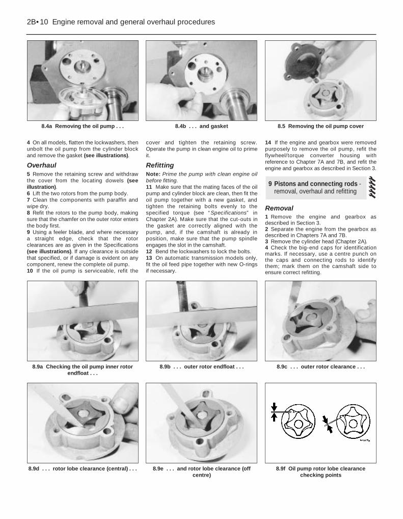
4 On all models, flatten the lockwashers, thenunbolt the oil pump from the cylinder blockand remove the gasket (see illustrations).
Overhaul5 Remove the retaining screw and withdrawthe cover from the locating dowels (seeillustration).6 Lift the two rotors from the pump body.7 Clean the components with paraffin andwipe dry.8 Refit the rotors to the pump body, makingsure that the chamfer on the outer rotor entersthe body first.9 Using a feeler blade, and where necessarya straight edge, check that the rotorclearances are as given in the Specifications(see illustrations). If any clearance is outsidethat specified, or if damage is evident on anycomponent, renew the complete oil pump.10 If the oil pump is serviceable, refit the
cover and tighten the retaining screw.Operate the pump in clean engine oil to primeit.
RefittingNote: Prime the pump with clean engine oilbefore fitting.11 Make sure that the mating faces of the oilpump and cylinder block are clean, then fit theoil pump together with a new gasket, andtighten the retaining bolts evenly to thespecified torque (see “Specifications” inChapter 2A). Make sure that the cut-outs inthe gasket are correctly aligned with thepump, and, if the camshaft is already inposition, make sure that the pump spindleengages the slot in the camshaft.12 Bend the lockwashers to lock the bolts.13 On automatic transmission models only,fit the oil feed pipe together with new O-ringsif necessary.
14 If the engine and gearbox were removedpurposely to remove the oil pump, refit theflywheel/torque converter housing withreference to Chapter 7A and 7B, and refit theengine and gearbox as described in Section 3.
Removal1 Remove the engine and gearbox asdescribed in Section 3.2 Separate the engine from the gearbox asdescribed in Chapters 7A and 7B.3 Remove the cylinder head (Chapter 2A).4 Check the big-end caps for identificationmarks. If necessary, use a centre punch onthe caps and connecting rods to identifythem; mark them on the camshaft side toensure correct refitting.
9 Pistons and connecting rods -removal, overhaul and refitting
2B•10 Engine removal and general overhaul procedures
8.4a Removing the oil pump . . . 8.5 Removing the oil pump cover
8.9f Oil pump rotor lobe clearancechecking points
8.9e . . . and rotor lobe clearance (offcentre)
8.9d . . . rotor lobe clearance (central) . . .
8.9c . . . outer rotor clearance . . .8.9b . . . outer rotor endfloat . . .8.9a Checking the oil pump inner rotorendfloat . . .
8.4b . . . and gasket

5 Turn the crankshaft so that No 1 crankpin isat its lowest point. Using a 1⁄2 in AF socket,unscrew the big-end bearing bolts (998 cc) ornuts (1275 cc).6 Withdraw the cap complete with thebearing shell (see illustration).7 Using the handle of a hammer, tap thepiston and connecting rod from the bore andwithdraw it from the top of the cylinder block.8 Loosely refit the cap to the connecting rod.9 Repeat the procedure given in paragraphs,5 to 8 on No 4 piston and connecting rod,then turn the crankshaft through half a turnand repeat the procedure on No 2 and No 3pistons.
Overhaul10 Examine the pistons for ovality, scoring,and scratches. Check the connecting rods forwear and damage (see illustration).
11 If the pistons or connecting rods are to berenewed on the 1275 cc engine and 1987-on998 cc engines, it is recommended that thiswork is carried out by a Rover dealer, who willhave the necessary tooling to extract thegudgeon pins from the connecting rods.12 To remove the pistons from theconnecting rods on the 998 cc engine, extractthe circlips and push out the gudgeon pin. Ifthe ambient temperature is below 20°C (68°F),heat the piston in hot water first.13 Check the small-end bushes for wear, andif necessary have a Rover dealer fit and reamnew bushes.14 Lubricate the gudgeon pin and bores withgraphite oil, then locate the connecting rod inthe piston as shown (see illustration), andpress in the gudgeon pin. Note that thediagonal split on the connecting rod must facethe camshaft side of the piston. Fit thecirclips.15 If new rings are to be fitted to the originalpistons, expand the old rings over the top ofthe pistons. The use of two or three old feelerblades will be helpful in preventing the ringsdropping into empty grooves. Note that the oilcontrol ring is in three sections.16 Before fitting the new rings to the piston,insert them into the cylinder bore and use afeeler blade to check that the end gaps arewithin the specified limits.17 After fitting the rings, check thecompression rings for groove clearancesusing a feeler blade (see illustration). Makesure that the word “Top”, where marked onthe compression rings, is towards the top of
the piston. Arrange the compression ring gapsat 90 degrees to each other on the camshaftside of the piston.
Refitting18 Clean the backs of the bearing shells andthe recesses in the connecting rods andbig-end caps.19 Press the big-end bearing shells into theconnecting rods and caps in their correctpositions and oil them liberally (seeillustrations).20 Fit a ring compressor to No 1 piston, theninsert the piston and connecting rod into No 1cylinder. With No 1 crankpin at its lowestpoint, drive the piston carefully into thecylinder with the wooden handle of a hammer,and at the same time guide the connectingrod onto the crankpin (see illustration). Makesure that the “Front” mark on the piston
Engine removal and general overhaul procedures 2B•11
2B
9.14 Correct relationship of the piston andconnecting rod on the 998 cc engine
9.20a Installing a piston and connectingrod
9.19b Lubricating a crankpin9.19a Installing a big-end bearing shell
9.17 Checking the compression ringgroove clearance (1275 cc engine)
9.10 Piston and connecting rodcomponents (1275 cc engine)
9.6 Removing a big-end bearing cap
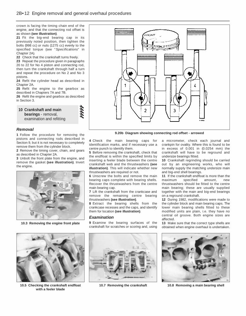
crown is facing the timing chain end of theengine, and that the connecting rod offset isas shown (see illustration).21 Fit the big-end bearing cap in itspreviously noted position, then tighten thebolts (998 cc) or nuts (1275 cc) evenly to thespecified torque (see “Specifications” inChapter 2A).22 Check that the crankshaft turns freely.23 Repeat the procedure given in paragraphs20 to 22 for No 4 piston and connecting rod,then turn the crankshaft through half a turnand repeat the procedure on No 2 and No 3pistons.24 Refit the cylinder head as described inChapter 2A.25 Refit the engine to the gearbox asdescribed in Chapters 7A and 7B.26 Refit the engine and gearbox as describedin Section 3.
Removal1 Follow the procedure for removing thepistons and connecting rods described inSection 9, but it is not necessary to completelyremove them from the cylinder block.2 Remove the timing cover, chain, and gearsas described in Chapter 2A.3 Unbolt the front plate from the engine, andremove the gasket (see illustration). Invertthe engine.
4 Check the main bearing caps foridentification marks, and if necessary use acentre punch to identify them.5 Before removing the crankshaft, check thatthe endfloat is within the specified limits byinserting a feeler blade between the centrecrankshaft web and the thrustwashers (seeillustration). This will indicate whether newthrustwashers are required or not.6 Unscrew the bolts and remove the mainbearing caps complete with bearing shells.Recover the thrustwashers from the centremain bearing cap.7 Lift the crankshaft from the crankcase andremove the remaining centre bearingthrustwashers (see illustration).8 Extract the bearing shells from thecrankcase recesses and the caps, and identifythem for location (see illustration).
Examination9 Examine the bearing surfaces of thecrankshaft for scratches or scoring and, using
a micrometer, check each journal andcrankpin for ovality. Where this is found to bein excess of 0.001 in (0.0254 mm) thecrankshaft will have to be reground andundersize bearings fitted. 10 Crankshaft regrinding should be carriedout by an engineering works, who willnormally supply the matching undersize mainand big-end shell bearings.11 If the crankshaft endfloat is more than themaximum specified amount, newthrustwashers should be fitted to the centremain bearing; these are usually suppliedtogether with the main and big-end bearingson a reground crankshaft.12 During 1982, modifications were made tothe cylinder block and main bearing caps. Thelower main bearing shells fitted to thesemodified units are plain, i.e. they have nocentral oil groove. Both engine sizes areaffected.13 Make sure that the correct type shells areobtained when engine overhaul is undertaken.
10 Crankshaft and mainbearings - removal,examination and refitting
2B•12 Engine removal and general overhaul procedures
10.3 Removing the engine front plate
10.8 Removing a main bearing shell10.7 Removing the crankshaft10.5 Checking the crankshaft endfloatwith a feeler blade
9.20b Diagram showing connecting rod offset - arrowed
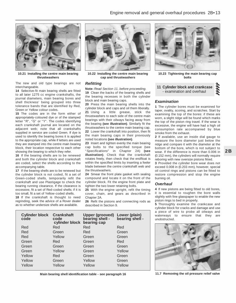
The new and old type bearings are notinterchangeable.14 Selective-fit main bearing shells are fittedto all later 1275 cc engine crankshafts, thejournal diameters, main bearing bores andshell thickness’ being grouped into threetolerance bands that are identified by Red,Green or Yellow colour codes.15 The codes are in the form either ofappropriately-coloured dye or of the stampedletter “R”, “G” or “Y”. The codes identifyingeach crankshaft journal are located on theadjacent web; note that all crankshaftssupplied in service are coded Green. If dye isused to identify the bearing bores it is appliedto the appropriate cap, while if letters are usedthey are stamped into the centre main bearingblock, their location respective to each othershowing the bearing to which they refer. 16 If the bearing shells are to be renewedand both the cylinder block and crankshaftare coded, select the shells according to theaccompanying table.17 If the bearing shells are to be renewed butthe cylinder block is not coded, fit a set ofGreen-coded shells, temporarily refit thecrankshaft and use Plastigage to check thebearing running clearance. If the clearance isexcessive, fit a set of Red-coded shells; if it istoo small, fit a set of Yellow-coded shells.18 If the crankshaft is thought to needregrinding, seek the advice of a Rover dealeras to whether undersize shells are available.
RefittingNote: Read Section 11, before proceeding.19 Clean the backs of the bearing shells andthe bearing recesses in both the cylinderblock and main bearing caps.20 Press the main bearing shells into thecylinder block and caps and oil them liberally.21 Using a little grease, stick thethrustwashers to each side of the centre mainbearings with their oilways facing away fromthe bearing (see illustration). Similarly fit thethrustwashers to the centre main bearing cap. 22 Lower the crankshaft into position, then fitthe main bearing caps in their previouslynoted locations (see illustration).23 Insert and tighten evenly the main bearingcap bolts to the specified torque (see“Specifications” in Chapter 2A) (seeillustration). Check that the crankshaftrotates freely, then check that the endfloat iswithin the specified limits by inserting a feelerblade between the centre crankshaft web andthe thrustwashers.24 Smear the front plate gasket with sealingcompound and locate it on the front of thecylinder block. Fit the engine front plate andtighten the two lower retaining bolts.25 With the engine upright, refit the timingcover, chain, and gears as described inChapter 2A.26 Refit the pistons and connecting rods asdescribed in Section 9.
Examination1 The cylinder bores must be examined fortaper, ovality, scoring, and scratches. Start byexamining the top of the bores: if these areworn, a slight ridge will be found which marksthe top of the piston ring travel. If the wear isexcessive, the engine will have had a high oilconsumption rate accompanied by bluesmoke from the exhaust.2 If available, use an inside dial gauge tomeasure the bore diameter just below theridge and compare it with the diameter at thebottom of the bore, which is not subject towear. If the difference is more than 0.006 in(0.152 mm), the cylinders will normally requirereboring with new oversize pistons fitted.3 Provided the cylinder bore wear does notexceed 0.008 in (0.203 mm), however, specialoil control rings and pistons can be fitted torestore compression and stop the engineburning oil.
Overhaul4 If new pistons are being fitted to old bores,it is essential to roughen the bore wallsslightly with fine glasspaper to enable the newpiston rings to bed in properly.5 Thoroughly examine the crankcase andcylinder block for cracks and damage and usea piece of wire to probe all oilways andwaterways to ensure that they areunobstructed.
11 Cylinder block and crankcase- examination and overhaul
Engine removal and general overhaul procedures 2B•13
2B
10.23 Tightening the main bearing capbolts
11.7 Removing the oil pressure relief valveMain bearing shell identification table - see paragraph 16
Cylinder block Crankshaft Upper (grooved) Lower (plain)code code bearing shell - bearing shell -
cylinder block bearing capRed Red Red RedRed Green Red GreenRed Yellow Green GreenGreen Red Green RedGreen Green Green GreenGreen Yellow Green YellowYellow Red Green GreenYellow Green Yellow GreenYellow Yellow Yellow Yellow
10.22 Installing the centre main bearingcap and thrustwashers
10.21 Installing the centre main bearingthrustwashers

6 Check the tappet bores for wear andscoring; if excessive, they can be reamed andoversize tappets fitted.7 Unscrew the oil pressure relief valve capand remove the valve and spring (seeillustration). Check the valve seating forexcessive wear and check that the spring freelength is as specified. Renew the valve andspring as necessary, and refit them to thecylinder block.
Adjustment1 With the engine/gearbox refitted to the car,make a final check to ensure that everything
has been reconnected and that no rags ortools have been left in the enginecompartment. 2 If new pistons or crankshaft bearings havebeen fitted, turn the carburettor slow runningscrew in about half a turn to compensate forthe initial tightness of the new components.3 Pull the choke fully out and start the engine.This may take a little longer than usual as thefuel pump and carburettor float chamber maybe empty.4 As soon as the engine starts, push in thechoke until the engine runs at a fast tickover.Check that the oil pressure light goes out.5 Check the oil filter, fuel hoses, and waterhoses for leaks.6 Run the engine until normal operatingtemperature is reached, then adjust the slowrunning as described in Chapter 4.
7 Drive the car for five to ten miles, then allowthe engine to cool and remove the valvecover. Working in the order shown (seeillustration 4.3 in Chapter 2A), loosen half aturn, then immediately tighten, each cylinderhead nut to the specified torque (see“Specifications” in Chapter 2A). After theengine has completely cooled, readjust thevalve clearances as described in Chapter 2A,then refit the valve cover.8 If new pistons or crankshaft bearings havebeen fitted, the engine must be run-in for thefirst 500 miles (800 km). Do not exceed 45mph (72 km/h), operate the engine at fullthrottle, or allow the engine to labour in anygear.
12 Engine - adjustment aftermajor overhaul
2B•14 Engine removal and general overhaul procedures