chapter 2: smoothing in dynamic mesh - mr-cfd · chapter 2: smoothing in dynamic mesh this set of...
TRANSCRIPT

Chapter 2: Smoothing in Dynamic Mesh
This set of tutorial illustrates the setup of a dynamic mesh by using the smoothing method. The purpose
of this tutorial is to understand the smoothing parameters, how they work and what is their effect on
the mesh behavior. You will be playing with the parameters to assess their effect on the mesh.
Smoothing can handle only small displacements. So for larger displacements it has to be associated
with the remeshing method. Also it can only be applied to tri and tet elements as a first step and then
extended to quad elements. In smoothing method nodes are connected together as a network. So iwith
smoothing method the edges linking the nodes react like a sponge/spring. So during this there is no
addition or deletion of cells. This is one of the reason why smoothing is applicable to only small dis-
placements.
This tutorial is written with the assumption that you are familiar with the ANSYS Fluent navigation pane
and menu structure. Some steps in the setup and solution procedure will not be shown explicitly.
2.1. Preparation
2.2. Reading and Checking the Mesh
2.3. Specifying Solver and Analysis Type
2.4. Specifying Dynamic Mesh Settings
2.5. Checking the Mesh Motion
2.6. Changing Settings and Checking the Effect
2.7. Changing Mesh Method Settings
2.8. Using a Small Spring Constant Factor
2.9. Smooth a Quad Mesh
2.10. Smooth a Mixed Mesh
2.11. Another Type of Mixed Mesh
2.12. Summary
2.1. Preparation
1. Copy the files (smooth.msh, metal-sheet.msh, prism_layer.msh, w_hex.mesh, vibration.c,
profile-smooth.prof, and piston.prof) to your working folder.
2. Launch Fluent.
a. Select 3D under Dimension in the Fluent Launcher dialog box.
b. Ensure that Display Mesh After Reading is enabled under Display Options in the Fluent
Launcher dialog box. This will ensure that the mesh is displayed automatically after reading.
c. Ensure that the option Workbench Color Scheme under Display Options is disabled.
d. Retain the option of Serial under Processing Options.
e. Make sure you have set the correct working directory in the General Options tab.
1Release 15.0 - © SAS IP, Inc. All rights reserved. - Contains proprietary and confidential information
of ANSYS, Inc. and its subsidiaries and affiliates.

f. Click OK to start Fluent.
Note
• Double Precision is recommended when moving deforming mesh is handling
very thin cells (ie: width of micron - µm).
• Use of Parallel Processing Options (associated with a number of processors) is
recommended if you want to speed up your simulation.
2.2. Reading and Checking the Mesh
1. Read the mesh file smooth.msh.
File → Read → Mesh...
2. Check the mesh.
General → Check
ANSYS Fluent will perform various checks on the mesh and will report the progress in the console. Ensure
that the reported minimum volume is a positive number.
3. In the mesh display check each surface of the geometry so that you know which surface will be moved.
a. Open the Mesh Display dialog box.
Display → Mesh...
Release 15.0 - © SAS IP, Inc. All rights reserved. - Contains proprietary and confidential informationof ANSYS, Inc. and its subsidiaries and affiliates.2
Smoothing in Dynamic Mesh

b. Select bottom and click Display. Only this edge will be displayed in the graphics window.
c. Select other surfaces one by one and click Display to check which displayed surface represents
which name.
d. Select all Surfaces and click Display to display the full mesh.
4. Check the scale of the mesh to understand the dimensions of the mesh.
General → Scale...
2.3. Specifying Solver and Analysis Type
For moving deforming mesh you require the transient solver. Select Transient under Time in the
Solver group box.
3Release 15.0 - © SAS IP, Inc. All rights reserved. - Contains proprietary and confidential information
of ANSYS, Inc. and its subsidiaries and affiliates.
Specifying Solver and Analysis Type
2.4. Specifying Dynamic Mesh Settings
Dynamic Mesh
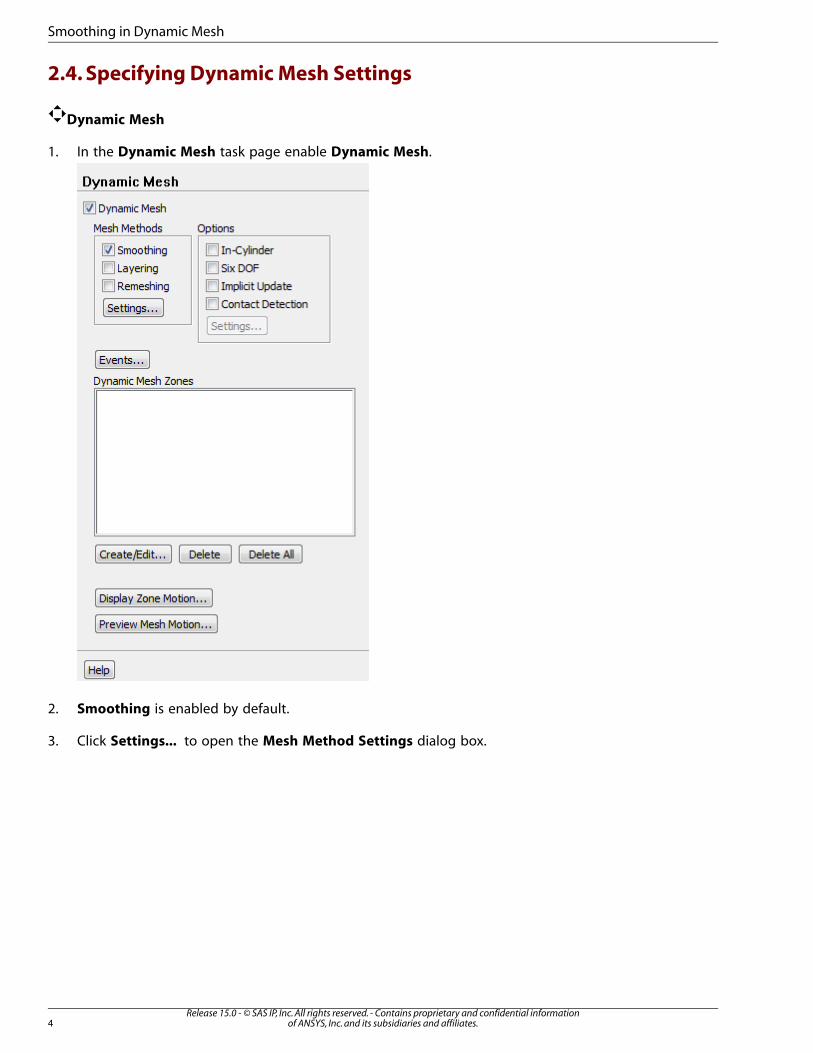
1. In the Dynamic Mesh task page enable Dynamic Mesh.
2. Smoothing is enabled by default.
3. Click Settings... to open the Mesh Method Settings dialog box.
Release 15.0 - © SAS IP, Inc. All rights reserved. - Contains proprietary and confidential informationof ANSYS, Inc. and its subsidiaries and affiliates.4
Smoothing in Dynamic Mesh

Note
For this section you will retain the default settings and check the effect on the mesh.
4. Check the default settings and close the Mesh Method Settings dialog box.
5. Before defining a motion to one of the surface zones, to assign a motion to the boundary(s) you will
need to read the motion profile file.
Define → Profiles...
5Release 15.0 - © SAS IP, Inc. All rights reserved. - Contains proprietary and confidential information
of ANSYS, Inc. and its subsidiaries and affiliates.
Specifying Dynamic Mesh Settings

a. Click Read... in the Profiles dialog box to open the Select File dialog box.
b. Select the profile-smooth.prof file in the Select File dialog box and click OK.
c. Close the Profiles dialog box.
6. Click Create/Edit... under the Dynamic Mesh Zones group box.
Release 15.0 - © SAS IP, Inc. All rights reserved. - Contains proprietary and confidential informationof ANSYS, Inc. and its subsidiaries and affiliates.6
Smoothing in Dynamic Mesh

a. In the Dynamic Mesh Zones dialog box retain the selection of bottom from the Zone Names
drop-down list.
b. Retain the selection of Rigid Body in the Type group box.
c. Retain the selection of profile-name from the Motion UDF/Profile drop-down list.
d. In the Meshing Options tab retain 0 for Cell Height as we are not deleting any cells.
e. Click Create.
f. Close the Dynamic Mesh Zones dialog box.
2.5. Checking the Mesh Motion
Click Preview Mesh Motion... in the Dynamic Mesh task page.
7Release 15.0 - © SAS IP, Inc. All rights reserved. - Contains proprietary and confidential information
of ANSYS, Inc. and its subsidiaries and affiliates.
Checking the Mesh Motion

1. Enter 0.002 for Time Step Size.
2. Enter 100 for Number of Time Steps.
3. Click Apply.
4. Save the case file, smooth.cas.gz.
File → Write → Case...
File → Write → Case...
Note
Previewing a mesh, allows you to quickly check the quality of the mesh motion
throughout the simulation cycle but, it updates the node locations. So the initial position
won’t be restored. Thus save the case before clicking on Preview.
5. Click Preview.
Note
On clicking Preview after some time steps you will get the negative volume error.
If you zoom near the bottom layer you can see some very bad cells which result in the
negative volume error. So you need to make some changes for the appropriate settings
for smoothing.
Release 15.0 - © SAS IP, Inc. All rights reserved. - Contains proprietary and confidential informationof ANSYS, Inc. and its subsidiaries and affiliates.8
Smoothing in Dynamic Mesh

2.6. Changing Settings and Checking the Effect
Now to apply proper smoothing method to the mesh you need to change the settings and also add
to the left and right side additional dynamic mesh zone.
1. Read the previously saved case file smooth.cas.gz.
File → Read → Case...
A Question dialog box appears.
Click OK to discard the old mesh.
2. To create additional dynamic zones click Create/Edit... under the Dynamic Mesh Zones group box.
9Release 15.0 - © SAS IP, Inc. All rights reserved. - Contains proprietary and confidential information
of ANSYS, Inc. and its subsidiaries and affiliates.
Changing Settings and Checking the Effect

a. Select left-side from the Zone Names drop-down list.
i. Select Deforming from the Type drop-down list
ii. In the Meshing Options tab retain the selection of Smoothing and deselect Remeshing as
you do not want to remesh anything on this wall.
iii. Click Zone Scale Info... to get the minimum and maximum length.
iv. From the Zone Scale Info dialog box enter 0.029 for Minimum Length Scale.
Release 15.0 - © SAS IP, Inc. All rights reserved. - Contains proprietary and confidential informationof ANSYS, Inc. and its subsidiaries and affiliates.10
Smoothing in Dynamic Mesh

v. Enter 0.03 for Maximum Length Scale.
vi. Enter 0.5 for Maximum Skewness.
vii. In the Geometry Definition tab select plane from the Definition drop-down list.
Note
Since Fluent does not know anything about the geometry you need to enter
the information so that it will be able to project and move the nodes on the
surface.
viii. Retain 0 for X and Y in the Point on Plane group box.
ix. Enter 1 for X in the Plane Normal group box.
x. Click Create.
b. Select right-side from the Zone Names drop-down list.
i. Enter the same settings as you have done for left-side.
ii. In the Geometry Definition tab enter 0.3 for X in the Point on Plane group box.
Note
This value is obtained from the Scale Mesh dialog box.
iii. Click Create.
c. Close the Dynamic Mesh Zones dialog box.
3. Save the case file, smooth-test.cas.gz.
File → Write → Case...
4. Click Preview Mesh Motion... in the Dynamic Mesh task page.
• Click Preview.
11Release 15.0 - © SAS IP, Inc. All rights reserved. - Contains proprietary and confidential information
of ANSYS, Inc. and its subsidiaries and affiliates.
Changing Settings and Checking the Effect

Note
The bottom wall moves up much further than in the previous case. As the bottom
wall moves up and down you can see that only the cells close to the wall are im-
pacted by the displacement of the wall. As the wall moves up the cells are com-
pressed and as the wall moves down the cells are stretched.
2.7. Changing Mesh Method Settings
1. Read the previously saved case file smooth-test.cas.gz.
File → Read → Case...
A Question dialog box appears.
Click OK to discard the old mesh.
Release 15.0 - © SAS IP, Inc. All rights reserved. - Contains proprietary and confidential informationof ANSYS, Inc. and its subsidiaries and affiliates.12
Smoothing in Dynamic Mesh

2. In the Smoothing tab of the Mesh Method Settings dialog box change Spring Constant Factor to
0.2.
3. Click Preview Mesh Motion... in the Dynamic Mesh task page.
• Click Preview.
13Release 15.0 - © SAS IP, Inc. All rights reserved. - Contains proprietary and confidential information
of ANSYS, Inc. and its subsidiaries and affiliates.
Changing Mesh Method Settings

Note
In this case you can observe that as the wall moves the cells that are impacted are
much more than in the previous case. Now, more cells which are further from the
bottom wall and inside the domain are affected by the wall motion. This results in
the cells being less compressed than in the previous case. So more cells are impacted
but you get a much better quality when you reduce the Spring Constant Factor
from 1 to 0.2.
2.8. Using a Small Spring Constant Factor
1. Read the previously saved case file smooth-test.cas.gz.
File → Read → Case...
A Question dialog box appears.
Click OK to discard the old mesh.
2. In the Smoothing tab of the Mesh Method Settings dialog box change Spring Constant Factor to
0.05.
Release 15.0 - © SAS IP, Inc. All rights reserved. - Contains proprietary and confidential informationof ANSYS, Inc. and its subsidiaries and affiliates.14
Smoothing in Dynamic Mesh

3. Click Preview Mesh Motion... in the Dynamic Mesh task page.
• Click Preview.
Note
As compared to the previous case you can observe that reducing the Spring Con-
stant Factor results in further more cells being impacted by the bottom wall motion.
This further increases the mesh quality since the impacted cells are less compressed.
So it all depends on how you want to impact the volume mesh or the inside of the
domain.
4. Close Fluent.
2.9. Smooth a Quad Mesh
In this section you will be using and studying the smoothing method on a quad mesh. The purpose of
this one is to handle the setting for such a mesh. As you will see in this example, the displacement of
the moving wall can either be small or quite big. A bigger displacement will increase the ratio of the
quad but will keep the quality of the mesh good enough.
The assumptions of the smoothing method for quad mesh are similar to the tri one, no addition or
deletion of elements. So the mesh is the same all the way through and there are only node movements
as the wall moves. So the connection between all the elements is maintained.
1. Launch Fluent.
a. Select 2D under Dimension in the Fluent Launcher dialog box.
15Release 15.0 - © SAS IP, Inc. All rights reserved. - Contains proprietary and confidential information
of ANSYS, Inc. and its subsidiaries and affiliates.
Smooth a Quad Mesh

b. Ensure that Display Mesh After Reading is enabled under Display Options in the Fluent
Launcher dialog box. This will ensure that the mesh is displayed automatically after reading.
c. Ensure that the option Workbench Color Scheme under Display Options is disabled.
d. Retain the option of Serial under Processing Options.
e. Make sure you have set the correct working directory in the General Options tab.
f. Click OK to start Fluent.
2. Read the mesh file metal-sheet.msh.
File → Read → Mesh...
3. In the mesh display check each surface of the geometry so that you know which surface will be moved.
a. Open the Mesh Display dialog box.
Display → Mesh...
b. Select bottom and click Display. Only this edge will be displayed in the graphics window.
c. Select other surfaces and click Display to check which displayed surface represents which name.
Note
For the tutorial to work there is some work to done on the metal-sheet which is the
middle part of the domain, (check Mesh Display dialog box) before starting the proced-
ure. The metal-sheet is presently defined as only one boundary condition. The end of
Release 15.0 - © SAS IP, Inc. All rights reserved. - Contains proprietary and confidential informationof ANSYS, Inc. and its subsidiaries and affiliates.16
Smoothing in Dynamic Mesh

the metal sheet is a stationary wall and that should not move. So as the boundary for
the dynamic mesh is going to be different from the top and bottom part of the metal
sheet we need to separate the zones.
4. To separate the faces of the metal sheet select Separate from the Mesh menu.
Mesh → Separate → Faces...
a. In the Separate Face Zones dialog box select metal-sheet from the Zones list.
b. Enter 80 for Angle.
c. Click Separate and close the Separate Face Zones dialog box.
Note
You can see that after separating there are three surfaces of the metal-sheet. Open
Mesh Display dialog box to check which surface corresponds to which face. In the
present case metal-sheet corresponds to lower face, metal-sheet:003 corresponds
to the upper face, and metal-sheet:011 corresponds to the side wall or end of the
metal sheet which you wanted to separate from the rest.
d. Check the mesh.
General → Check
ANSYS Fluent will perform various checks on the mesh and will report the progress in the console.
Ensure that the reported minimum volume is a positive number.
5. Check the scale of the mesh to understand the dimensions of the mesh.
General → Scale...
17Release 15.0 - © SAS IP, Inc. All rights reserved. - Contains proprietary and confidential information
of ANSYS, Inc. and its subsidiaries and affiliates.
Smooth a Quad Mesh

6. Select Transient under Time in the Solver group box.
7. In this tutorial, you will need a UDF to assign the motion of the metal sheet. So now you load and
compile the UDF. Details of UDF will be described in forthcoming lectures and tutorials.
Define → User-Defined → Functions → Compiled...
a. Click Add... under Source Files dialog box to open the Select File dialog box.
b. Select the vibration.c file in the Select File dialog box and click OK.
c. Click Build.
Release 15.0 - © SAS IP, Inc. All rights reserved. - Contains proprietary and confidential informationof ANSYS, Inc. and its subsidiaries and affiliates.18
Smoothing in Dynamic Mesh

Click OK in the Question dialog box that appears.
d. Click Load and then close the Compiled UDFs dialog box.
8. Dynamic Mesh
In the Dynamic Mesh task page enable Dynamic Mesh.
a. Smoothing is enabled by default.
b. Click Settings... to open the Mesh Method Settings dialog box.
c. In the Smoothing tab select All from the Elements group box.
19Release 15.0 - © SAS IP, Inc. All rights reserved. - Contains proprietary and confidential information
of ANSYS, Inc. and its subsidiaries and affiliates.
Smooth a Quad Mesh

d. Retain the default settings for the rest and click OK.
9. Now you will create the dynamic mesh zones for all the zones. Click Create/Edit... under the Dynamic
Mesh Zones group box.
a. In the Dynamic Mesh Zones dialog box select metal-sheet, which is the bottom face of the metal
sheet, from the Zone Names drop-down list.
i. Select User-Defined in the Type group box.
ii. In the Motion Attributes tab select vibration2::libudf from the Mesh Motion UDF drop-
down list.
iii. In the Meshing Options tab retain 0 for Cell Height as no cells are deleted or added.
iv. Click Create.
b. Now select metal-sheet:003 which is the top face of the metal sheet, from the Zone Names drop-
down list.
i. Select User-Defined in the Type group box.
ii. In the Motion Attributes tab select vibration1::libudf from the Mesh Motion UDF drop-own
list.
iii. Click Create.
Release 15.0 - © SAS IP, Inc. All rights reserved. - Contains proprietary and confidential informationof ANSYS, Inc. and its subsidiaries and affiliates.20
Smoothing in Dynamic Mesh

c. Now select metal-sheet:011 which is the side wall of the metal sheet, from the Zone Names drop-
down list.
i. Select Stationary in the Type group box.
ii. Retain the default settings in the Meshing Options tab.
iii. Click Create.
Note
Since the metal sheet is going to have displacement, in addition to the above zones
you need to define deforming zones to the upper and lower left side of the mesh.
d. Select lower-left from the Zone Names drop-down list.
i. Select Deforming in the Type group box.
ii. Disable Remeshing and retain Smoothing.
iii. Click Zone Scale Info... to get the minimum and maximum length.
iv. From the Zone Scale Info dialog box enter 0.029 for Minimum Length Scale.
v. Enter 0.03 for Maximum Scale.
vi. Enter 0.5 for Maximum Skewness.
vii. In the Geometry Definition tab select plane from the Definition drop-down list.
viii. Enter -5 for X in the Point on Plane group box. This value is obtained from Xmin from the
Scale Mesh dialog box. Retain 0 for Y.
ix. Retain 1 for X and 0 for Y in the Plane Normal group box.
x. Click Create.
e. Select upper-left from the Zone Names drop-down list.
i. Retain the same settings as set for lower-left.
21Release 15.0 - © SAS IP, Inc. All rights reserved. - Contains proprietary and confidential information
of ANSYS, Inc. and its subsidiaries and affiliates.
Smooth a Quad Mesh

ii. Click Create.
10. Close the Dynamic Mesh Zones dialog box.
11. Click Preview Mesh Motion... in the Dynamic Mesh task page.
1. Enter 0.002 for Time Step Size.
2. Enter 30 for Number of Time Steps.
3. Click Apply.
4. Save the case file, metal-sheet-test.cas.gz.
File → Write → Case...
Note
Previewing a mesh, allows you to quickly check the quality of the mesh motion
throughout the simulation cycle but, it updates the node locations. So the
initial position won’t be restored. Thus save the case before clicking on Preview.
5. Click Preview.
Release 15.0 - © SAS IP, Inc. All rights reserved. - Contains proprietary and confidential informationof ANSYS, Inc. and its subsidiaries and affiliates.22
Smoothing in Dynamic Mesh
Note
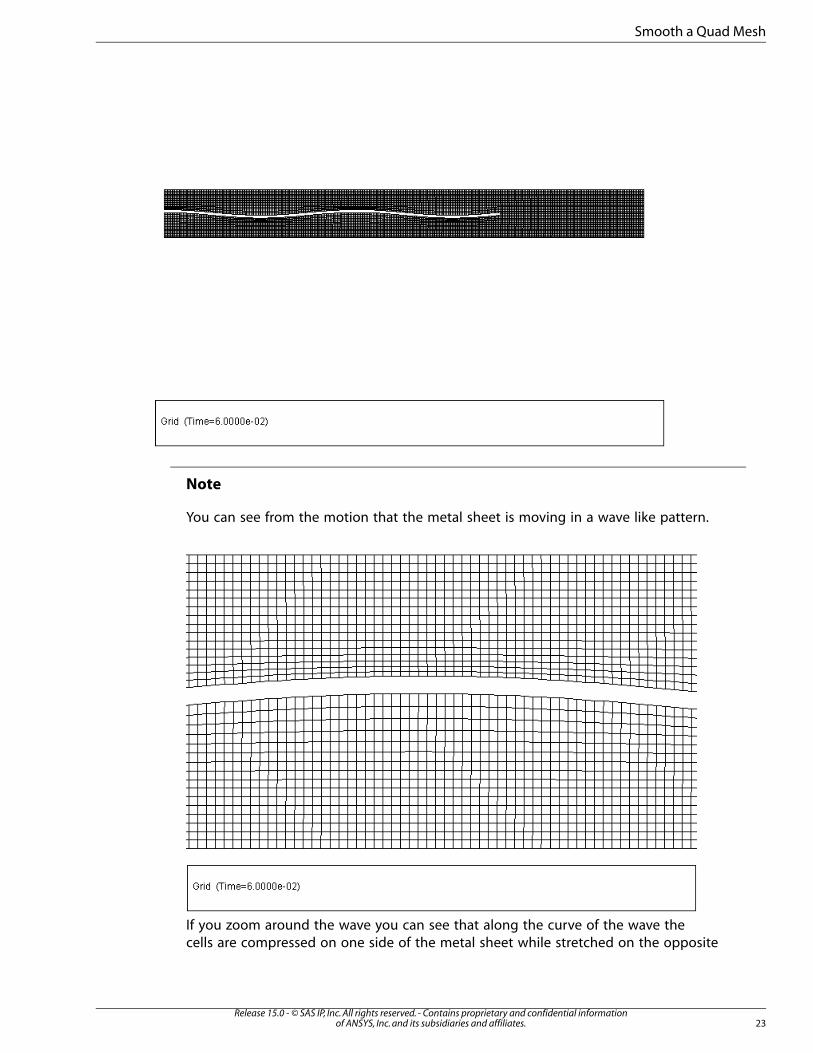
You can see from the motion that the metal sheet is moving in a wave like pattern.
If you zoom around the wave you can see that along the curve of the wave the
cells are compressed on one side of the metal sheet while stretched on the opposite
23Release 15.0 - © SAS IP, Inc. All rights reserved. - Contains proprietary and confidential information
of ANSYS, Inc. and its subsidiaries and affiliates.
Smooth a Quad Mesh

side. Also on the left end of the metal sheet, the upper-left and lower-left faces
of the mesh evolve as the metal-sheet end moves up and down the edge.
Changing Smoothing Settings for the Quad Mesh
Now you will change the settings
1. Read the previously saved case file metal-sheet-test.cas.gz.
File → Read → Case...
A Question dialog box appears.
Click OK to discard the old mesh.
Note
Now you will be concentrating on one part of the mesh, so zoom in on a section and
observe.
2. In the Smoothing tab of the Mesh Method Settings dialog box change Spring Constant Factor to
0.1.
Release 15.0 - © SAS IP, Inc. All rights reserved. - Contains proprietary and confidential informationof ANSYS, Inc. and its subsidiaries and affiliates.24
Smoothing in Dynamic Mesh

3. Click Preview Mesh Motion... in the Dynamic Mesh task page.
• Click Preview.
25Release 15.0 - © SAS IP, Inc. All rights reserved. - Contains proprietary and confidential information
of ANSYS, Inc. and its subsidiaries and affiliates.
Smooth a Quad Mesh

Note
By changing the Spring Constant Factor you can see that amount of compression
of the cells is not as dense as it was before when you had the Spring Constant
Factor at 1. Also comparatively more cells inside the domain are impacted by the
motion.
4. Now retaining the Spring Constant Factor of 0.1, change the Number of Iterations to 60 and check
the preview.
Release 15.0 - © SAS IP, Inc. All rights reserved. - Contains proprietary and confidential informationof ANSYS, Inc. and its subsidiaries and affiliates.26
Smoothing in Dynamic Mesh

Note
After changing the Number of Iterations you can see that the mesh does not stretch
as much as it was doing previously. You have a more smooth mesh all over the domain.
This one does take more time to redo the appropriate mesh, due to the increased
number of iterations, but the quality is preserved. This is also true for tri and tet meshes.
5. Close Fluent.
2.10. Smooth a Mixed Mesh
In this section you will be studying how to smooth a mixed mesh.
1. Launch Fluent.
a. Select 2D under Dimension in the Fluent Launcher dialog box.
b. Ensure that Display Mesh After Reading is enabled under Display Options in the Fluent
Launcher dialog box. This will ensure that the mesh is displayed automatically after reading.
c. Disable the option Workbench Color Scheme under Display Options.
d. Retain the option of Serial under Processing Options.
e. Make sure you have set the correct working directory in the General Options tab.
f. Click OK to start Fluent.
27Release 15.0 - © SAS IP, Inc. All rights reserved. - Contains proprietary and confidential information
of ANSYS, Inc. and its subsidiaries and affiliates.
Smooth a Mixed Mesh

2. Read the mesh file prism-layer.msh.
File → Read → Mesh...
The mesh has components of tri and quad. The quad are at the boundary layer of the piston.
3. In the mesh display check each surface of the geometry so that you know which surface will be moved.
a. Open the Mesh Display dialog box.
Display → Mesh...
b. Select piston and click Display. Only this edge will be displayed in the graphics window.
c. Select other surfaces one by one and click Display to check which displayed surface represents
which name.
d. Select all Surfaces and click Display to display the full mesh.
4. Check the scale of the mesh to understand the dimensions of the mesh.
General → Scale...
Release 15.0 - © SAS IP, Inc. All rights reserved. - Contains proprietary and confidential informationof ANSYS, Inc. and its subsidiaries and affiliates.28
Smoothing in Dynamic Mesh

5. Select Transient under Time in the Solver group box.
6. Before defining the dynamic mesh zones you will use a profile file to set the motion, so read pis-ton.prof.
Define → Profiles...
a. Click Read... in the Profiles dialog box to open the Select File dialog box.
b. Select the piston.prof file in the Select File dialog box and click OK.
29Release 15.0 - © SAS IP, Inc. All rights reserved. - Contains proprietary and confidential information
of ANSYS, Inc. and its subsidiaries and affiliates.
Smooth a Mixed Mesh

c. Close the Profiles dialog box.
7. Dynamic Mesh
In the Dynamic Mesh task page enable Dynamic Mesh.
a. Smoothing is enabled by default.
b. Click Settings... to open the Mesh Method Settings dialog box.
Release 15.0 - © SAS IP, Inc. All rights reserved. - Contains proprietary and confidential informationof ANSYS, Inc. and its subsidiaries and affiliates.30
Smoothing in Dynamic Mesh

c. In the Smoothing tab set Spring Constant Factor to 0.
Note
You change the Spring Constant Factor as you want the tetra in the upper part
of the geometry to move much more than those at the lower part or close to the
boundary.
d. Set the Number of Iterations to 40.
e. Retain the default settings for the rest and click OK.
8. Now you will create the dynamic mesh zones. Click Create/Edit... under the Dynamic Mesh Zones
group box.
31Release 15.0 - © SAS IP, Inc. All rights reserved. - Contains proprietary and confidential information
of ANSYS, Inc. and its subsidiaries and affiliates.
Smooth a Mixed Mesh

a. In the Dynamic Mesh Zones dialog box select cylinder from the Zone Names drop-down list.
i. Select Deforming in the Type group box. The cylinder zone consists of the side walls.
ii. In the Geometry Definition tab select cylinder from the Definition drop-down list.
iii. Enter 0.15 for the Cylinder Radius. This you can get from the Scale Mesh dialog box.
iv. Enter 0 for X and 1 for Y under the Cylinder Axis group box.
v. Click Create.
b. Now select fluid from the Zone Names drop-down list.
Release 15.0 - © SAS IP, Inc. All rights reserved. - Contains proprietary and confidential informationof ANSYS, Inc. and its subsidiaries and affiliates.32
Smoothing in Dynamic Mesh
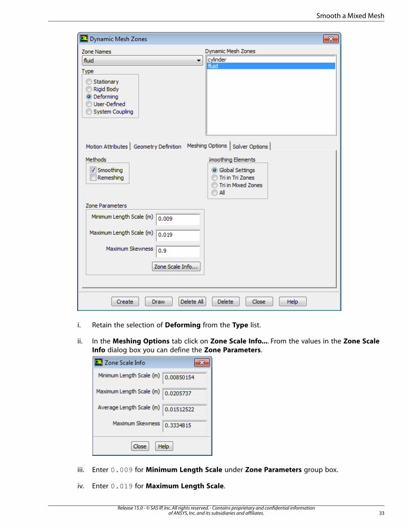
i. Retain the selection of Deforming from the Type list.
ii. In the Meshing Options tab click on Zone Scale Info.... From the values in the Zone Scale
Info dialog box you can define the Zone Parameters.
iii. Enter 0.009 for Minimum Length Scale under Zone Parameters group box.
iv. Enter 0.019 for Maximum Length Scale.
33Release 15.0 - © SAS IP, Inc. All rights reserved. - Contains proprietary and confidential information
of ANSYS, Inc. and its subsidiaries and affiliates.
Smooth a Mixed Mesh

v. Enter 0.9 for Maximum Skewness.
vi. Disable Remeshing from the Methods group box.
vii. Click Create.
c. Now select piston from the Zone Names drop-down list.
i. Select Rigid Body in the Type group box.
ii. Select piston from the Motion UDF/Profile drop-down list in the Motion Attributes tab.
iii. Retain the default settings in the Meshing Options tab.
iv. Click Create.
9. Close the Dynamic Mesh Zones dialog box.
10. Click Preview Mesh Motion... in the Dynamic Mesh task page.
1. Enter 0.02 for Time Step Size.
2. Enter 30 for Number of Time Steps.
3. Click Apply.
4. Save the case file, prism-layer-test.cas.gz.
File → Write → Case...
Note
Previewing a mesh, allows you to quickly check the quality of the mesh motion
throughout the simulation cycle but, it updates the node locations. So the initial
position won’t be restored. Thus save the case before clicking on Preview.
Release 15.0 - © SAS IP, Inc. All rights reserved. - Contains proprietary and confidential informationof ANSYS, Inc. and its subsidiaries and affiliates.34
Smoothing in Dynamic Mesh

5. Click Preview.
Note
You will get an error of negative cell volume. you will need some modifications in
the dynamic mesh zones setup.
If you look at the mesh and you zoom on the piston boundary condition, you will
notice that only the first cell has moved and therefore shrunk. It has absorbed all
the displacement till it crashed. To make it work you will need to add options in
the setting as shown below.
6. Read the previously saved case file, prism-layer-test.cas.gz.
A Question dialog box appears.
Click OK to discard the old mesh.
7. Open the Dynamic Mesh Zones dialog box.
a. For piston enable Deform Adjacent Boundary Layer with Zone in the Meshing Options
tab.
35Release 15.0 - © SAS IP, Inc. All rights reserved. - Contains proprietary and confidential information
of ANSYS, Inc. and its subsidiaries and affiliates.
Smooth a Mixed Mesh

b. Click Create and then Close the Dynamic Mesh Zones dialog box.
8. Click Preview Mesh Motion....
9. Click Preview.
Note
The quad elements move up and down. Their shape does not change with the
motion. Only the tri elements are impacted by the motion of the piston and hence
compressed while the piston moves up. This is the effect of enabling Deform Ad-
jacent Boundary Layer with Zone.
Release 15.0 - © SAS IP, Inc. All rights reserved. - Contains proprietary and confidential informationof ANSYS, Inc. and its subsidiaries and affiliates.36
Smoothing in Dynamic Mesh
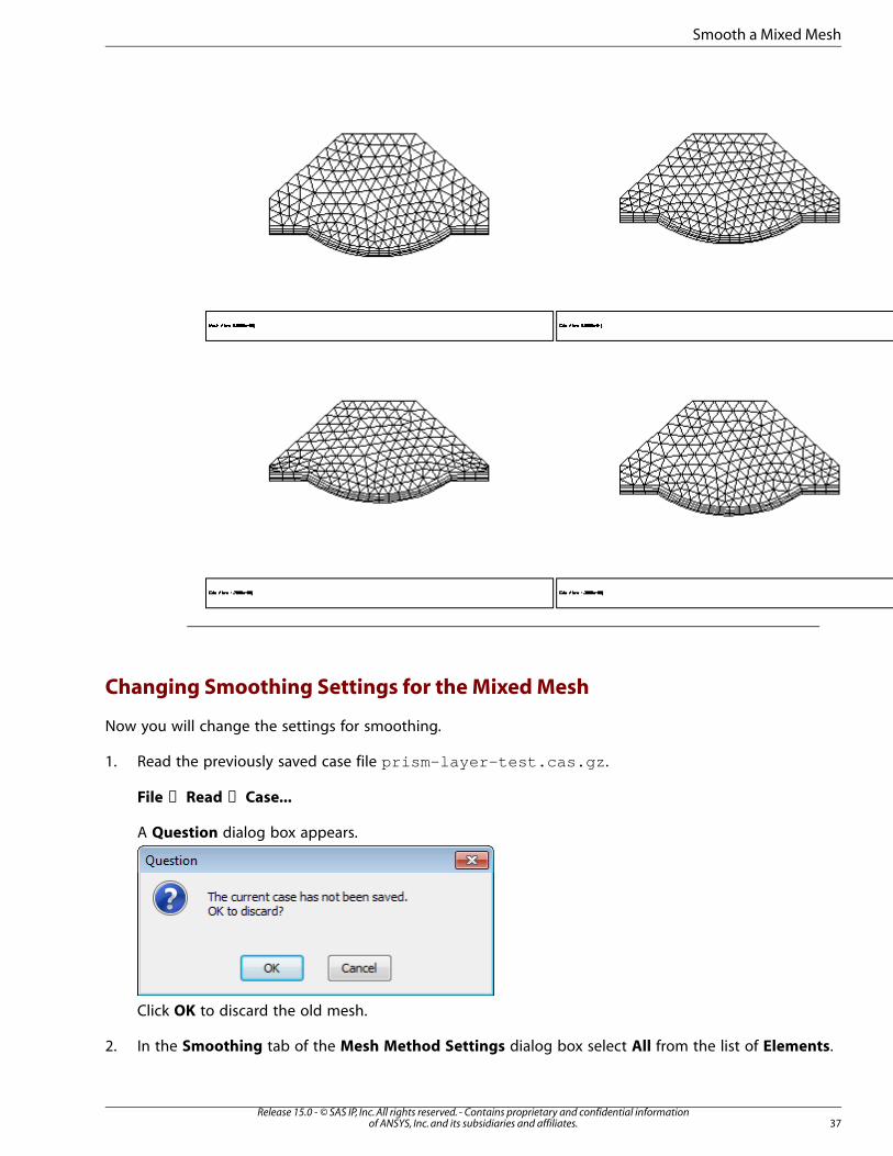
Changing Smoothing Settings for the Mixed Mesh
Now you will change the settings for smoothing.
1. Read the previously saved case file prism-layer-test.cas.gz.
File → Read → Case...
A Question dialog box appears.
Click OK to discard the old mesh.
2. In the Smoothing tab of the Mesh Method Settings dialog box select All from the list of Elements.
37Release 15.0 - © SAS IP, Inc. All rights reserved. - Contains proprietary and confidential information
of ANSYS, Inc. and its subsidiaries and affiliates.
Smooth a Mixed Mesh

3. Click OK and close the Mesh Method Settings dialog box.
4. Click Preview Mesh Motion... in the Dynamic Mesh task page.
• Click Preview.
Note
As the piston moves up the size of the boundary layer becomes smaller along with
the tri elements. If you go further ahead as the piston moves down the boundary
quad elements are stretched along with the tri elements. In this case you smooth
the tri and quad elements.
Changing Smoothing Settings and Dynamic Mesh Zone Settings for the Mixed
Mesh
Now you will change the settings for smoothing.
1. Read the previously saved case file prism-layer-test.cas.gz.
File → Read → Case...
A Question dialog box appears.
Release 15.0 - © SAS IP, Inc. All rights reserved. - Contains proprietary and confidential informationof ANSYS, Inc. and its subsidiaries and affiliates.38
Smoothing in Dynamic Mesh
Click OK to discard the old mesh.
2. In the Smoothing tab of the Mesh Method Settings dialog box select All from the list of Elements.
3. Click OK and close the Mesh Method Settings dialog box .
4. Open the Dynamic Mesh Zones dialog box.
a. For piston enable Deform Adjacent Boundary Layer with Zone in the Meshing Options tab.
b. Click Create and then Close the Dynamic Mesh Zones dialog box.
5. Click Preview Mesh Motion... in the Dynamic Mesh task page.
• Click Preview.
Note
In this case only the tri elements are compressed by activating the option Deform Ad-
jacent Boundary Layer with Zone. As the piston is moved down the tri elements get
stretched without having any impact on the quad elements at the boundary layer.
39Release 15.0 - © SAS IP, Inc. All rights reserved. - Contains proprietary and confidential information
of ANSYS, Inc. and its subsidiaries and affiliates.
Smooth a Mixed Mesh

2.11. Another Type of Mixed Mesh
In this section you will be studying another type of mixed mesh.
1. Read the mesh file w_hex.msh.
File → Read → Mesh...
Release 15.0 - © SAS IP, Inc. All rights reserved. - Contains proprietary and confidential informationof ANSYS, Inc. and its subsidiaries and affiliates.40
Smoothing in Dynamic Mesh

The mesh has components of tri and quad. The shape of the mesh is similar to the previous case.
The difference is that the quad cells are at the top of the geometry and tri cells are at the boundary
layer of the piston.
2. Check the mesh.
General → Check
Note
ANSYS Fluent will perform various checks on the mesh and will report the progress in
the console. Ensure that the reported minimum volume is a positive number.
3. In the mesh display check each surface of the geometry so that you know which surface will be moved.
a. Open the Mesh Display dialog box.
Display → Mesh...
b. Select piston and click Display. Only this edge will be displayed in the graphics window.
c. Select other surfaces one by one and click Display to check which displayed surface represents
which name.
d. Select all Surfaces and click Display to display the full mesh.
4. Check the scale of the mesh to understand the dimensions of the mesh.
41Release 15.0 - © SAS IP, Inc. All rights reserved. - Contains proprietary and confidential information
of ANSYS, Inc. and its subsidiaries and affiliates.
Another Type of Mixed Mesh

General → Scale...
Note
The mesh sizes are similar to the previous case which had the same mesh shape..
5. Before defining the dynamic mesh zones you will need to import the same profile file as in the previous
case. So read the file, piston.prof.
Define → Profiles...
a. Click Read... in the Profiles dialog box to open the Select File dialog box.
b. Select the piston.prof file in the Select File dialog box and click OK.
c. Close the Profiles dialog box.
6. Select Transient under Time in the Solver group box.
7. Dynamic Mesh
In the Dynamic Mesh task page enable Dynamic Mesh.
Release 15.0 - © SAS IP, Inc. All rights reserved. - Contains proprietary and confidential informationof ANSYS, Inc. and its subsidiaries and affiliates.42
Smoothing in Dynamic Mesh

a. Smoothing is enabled by default.
b. Click Settings... to open the Mesh Method Settings dialog box.
c. Set the Number of Iterations to 40.
d. Select Tri in Mixed Zones from the Elements group box.
Note
This will involve only the tri elements.
e. Retain the default settings for the rest and click OK.
8. Now you will create the dynamic mesh zones. Click Create/Edit... under the Dynamic Mesh Zones
group box.
a. In the Dynamic Mesh Zones dialog box select cylinder from the Zone Names drop-down list.
43Release 15.0 - © SAS IP, Inc. All rights reserved. - Contains proprietary and confidential information
of ANSYS, Inc. and its subsidiaries and affiliates.
Another Type of Mixed Mesh

i. Select Deforming in the Type group box. The cylinder zone consists of the side walls.
ii. In the Geometry Definition tab select cylinder from the Definition drop-down list.
iii. Enter 0.15 for the Cylinder Radius. This you can get from the Scale Mesh dialog box.
iv. Enter 0 for X and 1 for Y under the Cylinder Axis group box.
v. Disable Remeshing from the Methods group box in the Meshing Options tab.
vi. Click Zone Scale Info... in the Meshing Options.
vii. From the values in the Zone Scale Info dialog box enter 0.015 for Minimum Length Scale,
0.017 for Maximum Length Scale, and 0.9 for Maximum Skewness.
viii. Click Create.
b. Now select fluid from the Zone Names drop-down list.
i. Retain the selection of Deforming from the Type list.
Release 15.0 - © SAS IP, Inc. All rights reserved. - Contains proprietary and confidential informationof ANSYS, Inc. and its subsidiaries and affiliates.44
Smoothing in Dynamic Mesh

ii. In the Meshing Options tab click on Zone Scale Info.... From the values in the Zone Scale
Info dialog box you can define the Zone Parameters.
iii. Enter 0.012 for Minimum Length Scale under Zone Parameters group box.
iv. Enter 0.02 for Maximum Length Scale.
v. Enter 0.9 for Maximum Skewness.
vi. Click Create.
c. Now select piston from the Zone Names drop-down list.
i. Select Rigid Body in the Type group box.
ii. Select piston from the Motion UDF/Profile drop-down list in the Motion Attributes tab.
iii. In the Meshing Options tab enter 0 for Cell Height.
iv. Click Create.
9. Close the Dynamic Mesh Zones dialog box.
10. Click Preview Mesh Motion... in the Dynamic Mesh task page.
1. Enter 0.02 for Time Step Size.
2. Enter 30 for Number of Time Steps.
3. Click Apply.
4. Save the case file, w_hex_test.cas.gz.
File → Write → Case...
Note
Previewing a mesh, allows you to quickly check the quality of the mesh motion
throughout the simulation cycle but, it updates the node locations. So the initial
position won’t be restored. Thus save the case before clicking on Preview.
45Release 15.0 - © SAS IP, Inc. All rights reserved. - Contains proprietary and confidential information
of ANSYS, Inc. and its subsidiaries and affiliates.
Another Type of Mixed Mesh
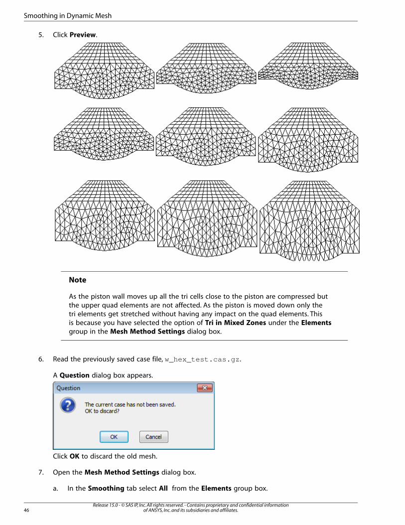
5. Click Preview.
Note
As the piston wall moves up all the tri cells close to the piston are compressed but
the upper quad elements are not affected. As the piston is moved down only the
tri elements get stretched without having any impact on the quad elements. This
is because you have selected the option of Tri in Mixed Zones under the Elements
group in the Mesh Method Settings dialog box.
6. Read the previously saved case file, w_hex_test.cas.gz.
A Question dialog box appears.
Click OK to discard the old mesh.
7. Open the Mesh Method Settings dialog box.
a. In the Smoothing tab select All from the Elements group box.
Release 15.0 - © SAS IP, Inc. All rights reserved. - Contains proprietary and confidential informationof ANSYS, Inc. and its subsidiaries and affiliates.46
Smoothing in Dynamic Mesh

b. Click OK and then Close the Mesh Method Settings dialog box.
8. Click Preview Mesh Motion....
9. Click Preview.
Note
The tri elements which are close to the piston wall, are compressed more than the
rest. Along with these the quad elements are also compressed. As you go further
ahead with preview mesh motion the piston moves downwards. The tri and the
quad elements are stretched.
10. Close Fluent.
2.12. Summary
In this second set of tutorials, you have gone through the second mesh method of moving deforming
mesh, which is Smoothing.
You have initially studied cases with tri (and tet) cells and played with various options and parameters
of the Dynamic Mesh Zones or the Smoothing method itself.
47Release 15.0 - © SAS IP, Inc. All rights reserved. - Contains proprietary and confidential information
of ANSYS, Inc. and its subsidiaries and affiliates.
Summary

You then extended the use of the smoothing method to quad elements only and handled the changes
of parameters to improve the quality of the mesh all the way through the process of deformation.
You finally studied cases where the type of cells is mixed (tri and quad) and played with options that
conserved the quads undeformed during the motion or made them deformed like the tri.
Release 15.0 - © SAS IP, Inc. All rights reserved. - Contains proprietary and confidential informationof ANSYS, Inc. and its subsidiaries and affiliates.48
Smoothing in Dynamic Mesh