chapter 2 ultrasonics - candu owners group library/20053103.pdf · (2.2) hook'.law for an...
TRANSCRIPT

Chapter 2
Ultrasonics
2.1 Introduction
• Ultrasonic: > 20 KHz (> Audible limit, typicaJlya few MHz).
• Ultrasonics techniques are concerned with very high frequencies toavoid confusion with background noise.
• Sound waves propagate well in metal and poorly in aU.
• Ultrasonics rely on pulses of energy generated by an external source(tr8.Illlmitter).
• Modification is by the material between the source and the sensor.
• Back reflection (echo) is most common technique.
• Need to study wave propagation in matter.
2.2 Physics of Acoustic Waves
Compression Waves: Longitudinal in 1-D, Dilational in 3-D.
Shear Waves: Tra.nsYerae in 1-D, Torsional in 3-D.
Surface Waves: Raleigh waves.
Plate Waves: Lamb Waves.
To study above waves let us consider first 1-D waves.
13

14 CHAPTER 2. ULTRASONICS
2.2.1 1-D Plane Waves
• Consider a bar of length L supported by frictionless supports.
• Introduce an impulse disturbance at one end of the bar (rifle bullet,hammer, electrical spark, la.ser pulse, piezoelectric transducer, or ashove with the hand).
• A shove by hand will simply make the bar oscillate, with no relativemotions between the ends.
• A tap with a small hammer: there will be a period in which the leftface will have moved, while the right face remains undisturbed.
• Then, there will be an an ellJ8tic deformation.
NDT requires small disturbance:
= {+ Mdz +B.O.T. = e+Mdz= cha.nge in length of element= (e+de)-e= Mdz= ~
__ (8(/8,,) do: _ 8e& -Wi
dF., = ~., +¥:dz) - F"= dz.,
(2.1)
(2.2)
Hook'. Law for an elutic Material
E = ii.6.(1' = li.
AF., = AEM.6.£ =M¥: = AE~
dF., = AE~dz
(2.3)

2.2. PHYSICS OF ACOUSTIC WAVES
Force =mass X acceleration
F = mxadF", = dmx aa = ~dm = px Adz
dF", ~= pA 8t dz
Equating the two equations for dF"" one obtains the Wave Equation:
c, = If = speed of travel of stress wave in medium.
Elastic Constants
E = ,.(3)'+21' ) = Young's ModulusA+I'II = >. = Poi880n's Ratio2r+Xjk=G = ~ = = Bulk Modulus
2.2.2 Plane Longitudinal Waves
1-D compressive waves:
15
(2.4)
(2.5)
(2.6)
• Particle motion is oriented pa.rallel to the direction of travel (wavepropagation).
• Can travel in solids, liquids and gases.
• Speed:
c, = ~_ [ E(H) ]t, - ,{1+")(1-2,,j
It = Shea.r modulus, Lame constantE = Modules of ElasticityII = Poisson's Ratiop = Material density
(2.7)

16
2.2.3 Plane Transverse Waves
CHAPTER 2. ULTRASONICS
• Particle motion is oriented .L direction of motion.
• Can only travel in solids, but not in gases or liquids.
• Speed:
(2.8)
• C, > C" by a factor 1.5 for most materials
2.2.4 Bulk Waves
• Particle is not restricted to one direction.
• DilGtional Wave: &I1alogOUi to longitudinal
it = Clvi8 = ~ri = vector notation of dilational motion of wave front (2.9)r = direction of motion
C1 = v"+/"• Tor,ional Wave
~ = C1v2(
e = vector notation of dilational motion of torsional wa~2.10)C2 = I!p
2.2.5 Surface Waves
• Particles vibrate near the surface of a solid ofweekly bonded molecules.
• Particles move .L to the surface in &11 elliptical motion.
• Similar to wave left on surface of a still pond when a peddle is droppedinto it.
• Equation of fundamental wave:
~ - 8R: +(24 - 16T~)R~ +16(T~ - 1) =0 (2.11)

2.3. MODIFICATION 17
where R,. = Cn/C2, T. = C2/C1 = 0.5(1 - 2v)/(1 - 2v), where Cnis the speed of Rayleigh wave; Cn l'::l 0.9C2 for most metals; noteR,. = Cn/C2 is a function of v, so is C2/C1j for steel v = 0.29, copperv = 0.34, aluminum v = 0.34.
• Depth of penetration of the Rayleigh wave increases with increasingv.
• Cn changes with r/A, where Ais wavelength and r is surface radius ofcurvature.
• H r >> A, speed does bot change, as is the case with a fiat surface;then R,. l'::l 0 and T l'::l l.
• As r / A decreases, e.g. at sharp comers, speed increased and R,. increases.
• At r/A = 2.5, Cn approaches C2 , i.e. wave approaches a shear wavejat r/A = 0.7, Cn = l.28C2.
• At r / A = 0.5, wave becomes erratic due to phase difference as thetransmitted and re1l.ected half-waves fit into the rounded arc.
2.2.6 Lamb Waves
• Travel in thin material, i.e. plates, where thickness l'::l wavelength.
• Speed is determined by material density, frequency and wave type.
• Plate functions as a waveguide.
• Used in inspection of metal for horizontal separation.
2.3 Modification
2.3.1 Specific Acoustic Impedance
Particle displacement, e, due to a 1-D wave propagating in the z direction,can be described by a limple harmonic (oscillatory) motion as:
e= Aexp{j(wt - kz + 4>)} = Aexp{211"j(~ - X+4>)} (2.12)
where A is the wave amplitude, w = 27:f, T = l/f, f is wave frequency,k = 27:/A =w/C is wave number, C =Af is wave speed, 4> is initial phaseshift.

18 CHAPTER 2. ULTRASONICS
• Pressure due to wave in an elastic material: p = E~.
• Velocity of displacement: u =~.
• Specific Acoustic Impedance: Z =p/u = -E(k/w).
• For a longitudinal wave: IZI = E/C, = pclIC -1 = pC,.
• Material is defined acoustically by value of Z.
• in NDT we are looking for a change, which is reflected by change of Zalong the wave direction.
2.3.2 Refection and Transmission Coefficients
When a wave encounters a change in Z, Le. an interface, wave can be:transmitted, reflected or refracted. It can also change mode. These changesaffect the amplitude, pressure and power of wave. We will examine thesechanges in normal and oblique wave incidence.
Normal Incidence
As wave crosses a surface from a medium with Z = Zl to another with Z =
t
r
Z2, two conditions must be maintained:
Equilibrium: Force on one side of object is equal to that on the other side,leading to:
(2.13)
where F designates force and the subscripts i, r, and t designate,respectively, the incident, reflected and transmitted waves. Keeping

2.3. MODIFICATION 19
in mind that the area changes sign from one side to the other, thenPi =+Fi/(-Area, p. =-F./(-Area) and P, =+Ft/(+Area), whereP designates the magnitude of the pressure at the interface. This leadsto:
Continuity: Particle has to continue moving at same velocity, i.e.
U, =Ui - U.
(2.14)
(2.15)
where U designates the magnitude of velocity at the interface. Nowat the interface:
Z.=P,=Pi+ P.= Pi+ P• =1+RZ1• U, Ui - U. Pi/Zl - P./Z1 1 _ R (2.16)
where R is the pressure reflection coefficient. Then:
R= Z2- Z1ZI+Z2
Similarly, for pressure transmusion coefficient, T,
(2.17)
T = P, = Pi + p. =1 + p. =1 + R = 2Z1 (2.18)Pi Pi Pi ZI+Z2
Note that R + T i' 1, but R - T = 1. Why?
Amplitude Coeffieient.:
RA =A. = kIEIA. = p. =RAt klEIAt Pi (2.19)
TA = AI = PI/(k2~) =TkIEI/W =TZ1 = 2Z - 1 (2.20)At Pi/(K - lEI) k2~/W Z2 Zl +Z2
Note that here RA + TA = 1. Why?
Power eoeffieient.:
Power per unit area at wave front = Pwr = 0.5 X dress X strain X :
• 2 BIZ (B{)2 BIZ= 0.5E X stram X Bt = 0.5E X BIZ 8t
B{B{ EA2w2=0.5 X E BIZ Bt =0.5E(kA)(Aw) =0.5 C, =0.5ZA2..f,!.21)

20 CHAPTER 2. ULTRASONICS
Then
R - Pwrr _ ZI~ _ R2 _ R2pVJT- - 2- A-PWri ZI~
Tp_ PWrj _ Z2A~ _ Z2
T2 _ 4Z1Z2
tur- - - A-PWri ZIA~ ZI (ZI +Z2)2
Note that here R~VJT + 'I'J,VJT = 1. Why?
(2.22)
(2.23)
(2.24)
Oblique Incidence
Incident Wave: Longitudinal, at angle 81 with normal to interface, inmedium #1, with speed C1•
Reflected Wave: Longitudinal, at angle 811 with normal to interface, inmedium #2, with speed C1/.
Reflected Wave: Transverse, at angle 821 with normal to interface, inmedium #2 (81/ > 82'), with speed C2/.
Refracted Wave: Longitudinal, at angle 81" with normal to interface, inmedium #1, with speed C1•
Refracted Wave: Transverse, at angle 82" with normal to interface, inmedium #1 (81" > 82"), with speed C2•
Snell's Law: In a homogeneous isotropic solid:
sin 81 sin 811 sin 821 sin 81" sin 82"-c;- = C
1, = C
2, = -c;- = C
2
Therefore: 81" = 81 ,
Normal Incidence: 81 = 0, then no transverse waves are generated andthe refracted wave becomes the longitudinal wave.
First Critical Angle: reached when 811 = 'K/2. Beyond this angle longitudinal wave component disappear leaving only the shear component,C2/.
First Critical Angle: reached when 821 = 'K /2. Beyond this angle wave isconcentrated on surface (Rayleigh wave).
Reflection and Refraction Coefficients: relationships exist to describethese coefficients, but they are more complex than the case of normalincidence.

2.4. SOURCE/SENSOR 21
2.3.3 Loss of Pulse Energy
Even in the absence of a.n interface, the energy of a.n acoustic pulse will bedispersed by absorption (mechanical energy converted to heat), a.nd scattering (reflections at grain boundaries, small cracks a.nd other nonhomogeneities, importa.nt when grain size is 1/10 wavelength or larger).
Attenuation
At far fields, away from interference near the source, the pulse pressure canbe described by (not accounting for beam divergence):
P = Poexp(-aL) (2.25)
where L is dista.nce from source, a is the attenuation coefficient a.nd Po isthe pulse pressure at L = O. Alternatively,
PSound Pressure Level = SPL = 20logIO Po dB (2.26)
where the logarithm to base 10 is used to provide a larger qU&lltity to dealwith, called the Decibels (dB). Then one can define a.nother attenuationcoefficient, a in dB/m as:
P2aL = 20logIO PI (2.27)
where PI and P2 are the pressure at two consequent stations separated bydista.nce L.
2.4 Source/Sensor
2.4.1 'Iransducers
Piezoelectric tranaducera are commonly used to generate ultrasonic waves,as well as to detect it. Other less common methods include optical deflectionand capacitive displacement.
• Piezoelectricity is electricity or electric polarity due to pressure (crystalline substance)i simply a microphone.
• Convert electric energy to mechanical energy and verse-vera.
• Pressure on a piezoelectric transducer generates an electric signal (voltage).

22 CHAPTER 2. ULTRASONICS
• UsuaJIy made ofceramics (Barium Titanium, Lead Zirconate Titaniumor Lead Metaniobate), which are most sensitive but their sensitivitydecreases with times and are not suited at high temperatures.
• Quartz has low sensitivity, but maintains sensitivity for a long timeand is hard and resists water.
• Most ceramic and crystalline materials lose their piezoelectric properties above a certain temperature known as the Curie temperature, asthe solid change crystalline structure from symmetric to antisymmetric. This temperature limits the upper operating temperature of theprobe.
• Waves are generated as pulses for approximately 1 /-Is (1 to 10 cyclesof vibration).
2.4.2 Acoustic Equivalence
• A transducer consists of the ringing crystal and a ba.cking (Tungsten/epoxy ba.cldng).
• When the transducer is applied on a test material of acoustic impedance,Zl, one needs to match this impedance with that of the transducermaterial, Zo and the ba.cldng material, Z2.
• When an electric pulse field spike is applied on the transducer, impulsesof opposite signs will be excited at each interface of the crystal.
• The resulting stress wave will travel back and forth within the crystalas the oscilla.tions occur.
• The amplitudes of the reflected and transmitted waves are governedby the values if Zl and Z2.
• The ba.cking material is introduced to dampen oscilla.tions, which otherwise will be very severe.
• Maximum energy transfer between transducer and test material occurswhen Zo = Zl.
• A measure of the ringing ability of a transducer is:
Q = energy stored in crystal =... Zoenergy lost per cycle of vibration 2 Zl +Z2
(2.28)

2.4. SOURCE/SENSOR 23
• A high Q results in a longer crystal ringing and increased efficiencyand sensitivity (as a sensor), but poor frequency resolution; Good resolution means that subsequent rings do not interfere with each other.
2.4.3 Electric Equivalency
• Transducer is represented by a capacitance, Co. A varying capacitance,inductance, L, and resistance, are usually associated with it in parallel,together with a power source.
• Optimum oscillation at resonance frequency, when mechanical andelectric frequencies are equal:
1 ~ 12l1'V M = 2l1'..;r;lJO
(2.29)
where. is the mechanical stift'ness of the transducer and M is its mass.
• Tuning is achieved by varying the inductance L.
• The varying remtance is used to adjust pulse height (amplitude).
• The varying capacitance is used to adjust signal attenuation (decay).
• The frequency of the transducer is rated at the peak frequency, fp, i.e.the frequency at which the response of the transducer peaks.
• The frequency range is defined by the band width B = fb - f., wheref. &lid f. are the frequency at which the response of the probe reacheshalf its maximum power.
• The percentage b&lldwidth is defined as B* = lOO(Jb - f.)!fe.
• The central frequency is defined as fe = O.5(J. + fb}.
• The akewness of the response is defined as f./tw = (fp - f.)(J. - fp);ideally f./tw = 1.
2.4.4 Couplants
• Required to maximize energy tr&llSfer from transducer to test martial.
• It also smooths surface irregularities &lid excludes air between surfaces.

24 CHAPTER 2. ULTRASONICS
• Immersion method: de-aerated water can act as a couplant, test specimen and transducer, contacted by a column of water or a wheel-filledwith liquid.
• Contact materials placed between specimen and transducer includeoil, grease, glycerin, honey, water, or thickened water (water gel).
2.4.5 Beam Spreading
• Waves produced from a finite-size transducer can be visualized as beingemitted from different points in the transducer.
• Huygen's principle states however that an arbitrary wave form can beconstructed from a la.rge number of simple spherical waves of samefrequencies. Every wave surface can then be visualized as an envelopeof such elementary waves whose origin is 1oc&ted on a preceding wavesurface.
• Consider the two extreme points at a "line" transducer, draw fromeach point haJf a circle in the direction of wave propagation of radiusequal to the wave length with centre at the point, draw a tangent ofthe two semicircles parallel to the transducer (i.e. line connecting twoextreme points), this line represents the wave surface (front), now drawtwo more semicircles with radius twice the wavelength, the intersectionpoints of these new semicircles with the previous wave front representpoints on the envelope of the net combined wave emerging from thetransducer, repeat the above process a few times and you will see thatthese envelope points converge to a single point at which the wavefront becomes a plane, giving rise to a plane wave.
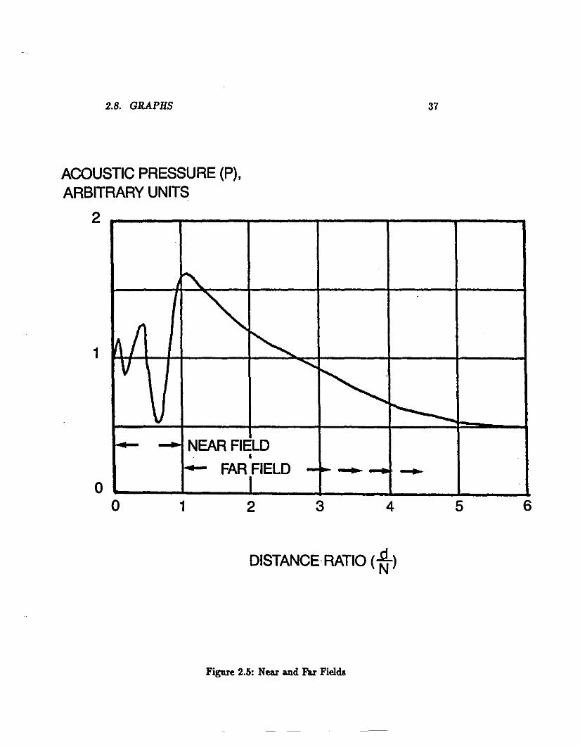
• The region before the convergence of the envelop points represents thenell" field, and when the piaae wave is formed one is in the fa,. filed.
• A typical transducer emits pulses lasting about 1 ps, then detects thereflected sigual perhaps 0.1 ps later. There is therefore a dead timeduring which reflections from the specimen are confused with the tallpulse of the initial pulse. This corresponds to a dead zone, i.e. thicknesswithin the specimen which can be directly examined.
• Since ultrasonic waves are not generated with exactly the same frequency or the same initial phase shift, but with the nominal frequencywithin a band, wave interference occurs within the near filed resulting

2.4. SOURCE/SENSOR 25
in erratic changes in the wave pressure, with the pressure varying fromzero to 2ZUo, where Uo is the velocity of the surface of the radiator(transducer), Zo is the acoustic impedance of the medium in whichthe wave is travelling.
• The near field length is defined by:
,p _ >..2 ,pN= 4>" "" 4>"
where d is the probe's diameter, and >.. is the wavelength.
• In the far field, the pressure decays smoothly such that:
(2.30)
(2.31)
(2.32)
where z designates a distance on the axis normal to the surface of theprobe. Note that larger probe diameters and higher frequencies resultin higher pressures.
• The acoustic pressure of the probe is also dependant on the angleaway from the beam axis. The longitudinal wave emitted from thetransducer is concentrated within an angle fi determined by directionof first minimum in diffraction pattern and can be determined from:
fi = 2sin-I {1.2 X10⁻³~~} "" 2sin-I e·~>..}
where C1 is the speed of the dilational wave in the load material inmIs, / is probe frequency in MHz, and d is probe diameter in mIll.
The use of a ll&lTOW beam, small fi, resulting in the so-called "searchunits'.
• Within the angle fi, the COll8tlUlt pressure boundary moves toward theprobe until a node is reached, creating the major lobe.
• Minor lobes also exist at larger angles due to the shear waves lUld thesurface waves, but are of little concern in. most NDT applications.
2.4.6 Selecting Criteria
To choose a good transducer as a source and 8en8Or, the following aspectsshould be considered:

26 CHAPTER 2. ULTRASONICS
1. Cost.
2. Material: ceramic, unless harsh environment (quartz).
3. Frequency: take into account test material, near filed size, requiredresolution.
4. Size: probe diameter affects divergence angle and near filed size.
5. Divergence angle: large divergence leads to exposure of wider &rea andvice versa. Divergence angle depends on size of transducer, frequencyand speed of wave in material.
6. Angle of incidence: ifnot normal UBe a wedge. Note that only longitudinal waves are generated, but wedge can be used to created transversewave as will be shown later.
7. Efficiency versus sensitivity.
8. Band width: small.
9. Flaw size ~ A.
10. Penetration: lower frequency decreases chance of scattering (allowinglarger penetration), but this comes at the expense of decreased res0
lution (ability to resolve closely spaced rellected signals).
11. Temperature: Curie tempera.ture.
2.5 Indication
• Normal beam, Bingle transducer (pulse echo).
• Normal beam, dual transducer (through transmission).
• Angle-beam, Bingle transducer (pulse echo).
• Angle-beam, dual transducer (pitch-catch).
2.5.1 Normal Incidence
Uses a lon~tudinal wave that enters perpendicular to surface of specimen.

2.5. INDICATION 27
Pulse Echo Technique
• Reflected signal is measured with same transducer (with a switch circuit) or two transducers located on the same side. This is the mostcommon method.
• In addition to the main pulse (initial echo), subsequent echo appearseparated by a time, t = 2z/C" where z is distance from probe toreflecting surface.
• In a flawless specimen a series of back echos, corresponding to the farend of the specimen appear, decreasing in intensity as the number ofecho increase.
• Appearance of a premature reflection indicates a flaw. Position ofsignal determines flaw location, while amplitude is an indication offlaw size.
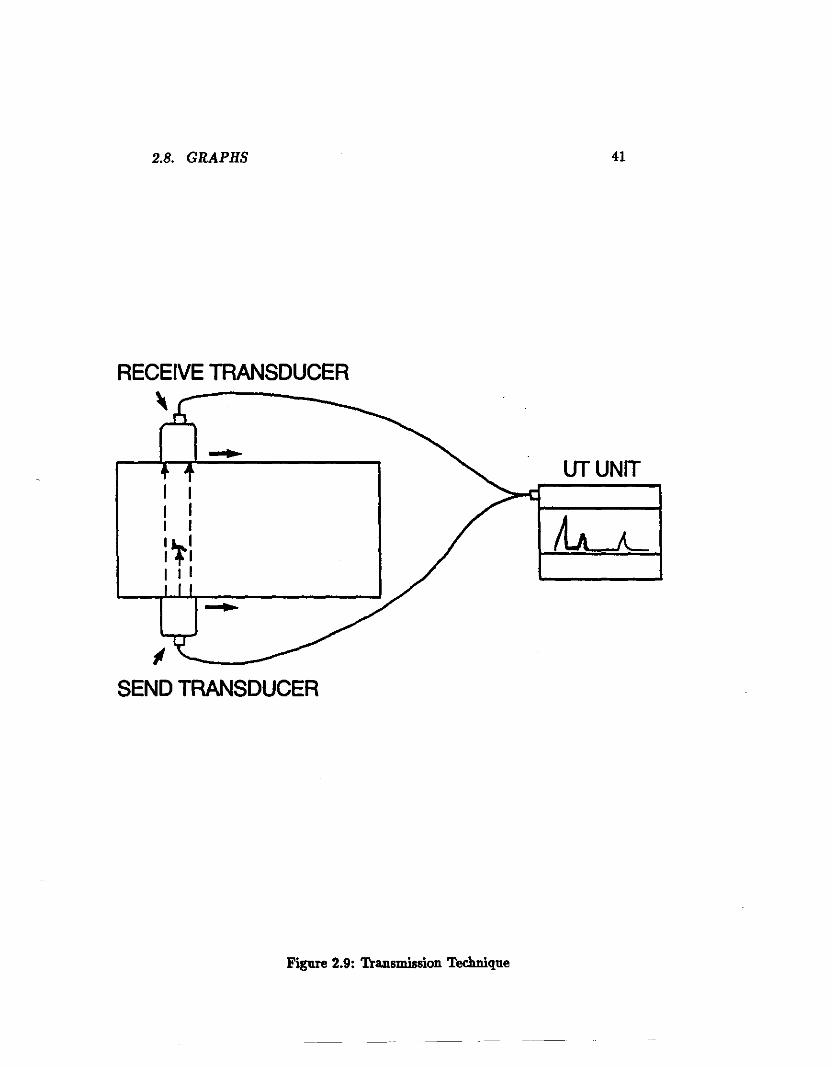
Transmission Technique
• Uses two transducers located at opposite ends of specimen, one actsas a lOurce and the other as a. receiver; also called pitch-catch method.
• Sound wave is genera.ted continuously and wave amplitude is measured, flaws cause reduction in amplitude.
• Typically used when no suitable reflection can be produced from flaws,such as in a highly dense medium, material with la.rge grain size orwhen many surface irregu1a.rities exist.
• Also used for thin sheets where pulse echo is impractical due to thedead zone effect. It is also used for the inspection of composites forlarge flaws.
2.5.2 Angle Beam
Single Probe
• Mode conversion, from longitudinal to transverse and vice versa, isused.
• Beam enters the specimen at an a.ngle, with the help of a plastic wedge.
• Can be used for areas that are inaccessible to normal beam incidence.

28 CHAPTER 2. ULTRASONICS
• Angle of incidence is chosen greater than first critical angle to eliminatelongitudinal wave in specimen.
• Inspection relies on transverse wave reflection; which does not necessary require perfectly perpendicular surface.
• One obtains a strong reflected signal only when there is a surfacenormal to the transverse wave produced in the inspected object.
• Transverse wave is reflected back as a transverse wave within the objected and is refracted as a longitudinal wave within the wedge fordetection by the probe; therefore indication is obtained by comparingthe return pulse to the incident pulse.
• When angle of incidence is equal to second critical angle, probe canbe used for IUJface inspection using the resulting Rayleigh wave.
Angle-Beam Dual TralUlducer
• Two separate _ding and receiving wedge probes are used, also calledpitch-catch method.
• Requires access to one aide of object only.
• Pulses ap~ in between the initial echo and the rear- wall echoindicate the presence of a flaw.
• If incident wave is at first critical angle, a surface wave is also created and detected, providing another reference corresponding to theshortest distanc:e between the probes; a law indication mould appeardOWDlltream of this signal.
• R.elative poaitioning offour indicationa (initial, surface, flaw and back)is used tod~e flaw poaition.
• Method is called "crack-tip" method,aince acatteriJl« from the tips ofa crack can be used to determine the crack size.
2.5.3 Scanning 'Thchniques
A-sean: 1·D data, one point at a time; display oftime-of-iight data (depth)and intensity information is also available; most widely used, gives flawtype, depth and location.

2.6. INTERPRETATION AND APPLICATIONS 29
B-scan: 2-D data, parallel set of A-scans; display of time-of-flight along aline on surface of test specimen.
C-scan: 3rd dimension added to 2-D scan by restricting the echoes to a particular time corresponding to a particular depth in the specimen; thusproviding a plan view of the object with the horizontal and verticalpositions of flaws indicated on the screen.
2.6 Interpretation and Applications
2.6.1 General
• Size offlaw depend on amplitude ofsignal, while location is determinedfrom time-of-flight.
• Real boundaries produces multiple period signals, spurious signal donot.
• Fatigue cracb are planar in shape and have well-defined boundaries,producing sharp distinct echoes; brittle fracture cracks produce theopposite effect.
• In inclusions, slag, porosity and large grain structures, produce notao-clean echoes; one might lose the rear-wall back echo signal due toscattering and the absence of a flat planar surface; loss of back echomay be a good indication that component has deteriorated.
• Preas fits: gears, turbine disks, roller bearings, wheels, pulleys etc.interfa.cea generate an ultrasonic response but in a regular fashion; ifprobes moves in a circula.r fashion one obtains a rea.aonably steadyappearance (while it it were a crack fatigue the indication will disappear at some direction); quality of fit depends on degree of energytransmission (signal amplitude).
• Bonding between dissimilar materials: a good bond will produce wellfocused echoes, while the echoes form a defective bond will be spreadover a wide time-of-flight range.
• False at-angie-rellections may appear at fillets on machined shafts.

30 CHAPTER 2. ULTRASONICS
2.6.2 Examination of Welds
• An angle beam is used, the distance at which it arrives at back surfaceis called the half-skip distance.
• The position of the first node, at full-skip distance, and the secondnode, twice full-skip distance, is determined using a second angulartransducer as a detector, enabling the skip distance to be determined.
• Welds are examjned by displacing the transducer from the half-skip tothe full-skip distance.
• A good weld will give a sharp signal pulse a little after the half-skipposition, as the wave has to travel some distance to the weld tip (rootbead) before being reflected.
• A poor weld, with lack of complete fusion on the side nearest thetransducer, signal will be received before the half-skip position, andon moving the probe the signal will move toward the half-skip position.
• The presence of an inclusion in the root bead will result in a signalthat becomes a maximum when the probe is at less than the half-skipdistance, as inclusion creates an acoustic impedance mismatch.
• Cracks and inclusions at other points in the weld will give indicationsas the probe moves from the half-skip to the full-skip position.
• Fall-length ICaIl of the weld can be obtained by moving the probe fromthe half-skip position to the full-skip position In a zigzag path alongthe centre-line of the weld.
2.6.3 Pipe Inspection
• An angular beam Is used, as the probe moves toward and past a defect,the echo will rise and fall.
• If the probe is very close to the expected defect, the law echo may bemasked by intemal refectiol1l in the wedge, but a dual probe techniquecan overcome this problem.
• Above can be done by pladng the source transducer in one end of thewedge and the receiving tr&Daducer at the other end; resulting in anincreaae in the travel distance and hence better indication when thewedge is very close to the defect.

·2.7. WORK PROBLEMS 31
2.6.4 Surface Wave Inspection
• Surface waves are generated either by a longitudinal wave probe placedon the surface without coupling, or with a wedge probe such that therefracted shear wave is just past the second critical angle.
• Surface wave are reflected on surface a.nomalies a.nd return to the transducer.
• Position of flaw ca.n be obtained by tapping with a slightly oily fingerin the travel path of the surface wave to cause the wave to be reflectedback to the transducer, once the tapping passes the defect it will notaffect the echo and the crack ca.n be located.
• Surface waves are sensitive not only to defects but also to other surfaceanomalies auch as pitting, oil, and other reflectors.
• Reflections occurring at curved aurfaces, particnlarly sharp comers,cause difticnlties in inspection.
2.6.5 Lamb Wave Inspection
• Used to inspect plates a.nd sheets for anomalies caused by a change insection thickness.
• Thickness change will result in an excitation of different modes, affecting the dispersion characteristics of the wave.
• Used for examinjng laminations and corrosion in metal plates anddelamination in composite materials.
2.7 Work Problems
1. Summarize in a table the definitions for the reflection coefIicients forthe amplitude, preaaure and power at the surface of a longitudinalwave of normal incidence on an interface. Compare the values of thesecoefIicients when:
(a) The acoustic impedances on both aides of the interface are equal.
(b) The wave is incident from a aide of large aooustic impedance toair.

32 CHAPTER 2. ULTRASONICS
(c) When the wave is incident from air on a surface of a large acousticimpedance.
Given the above results state the required criteria for good acousticcouplant and explain why such a couplant is needed.
2. An aluminium plate 50 mm thick is to be inspected ultrasonically usinga normal beam probe. If the attenuation coefficient in the material is85 dB/m, calculate the expected ratio of the pulse-echo heights of twosuccessive pulses.
3. For the same frequency and the same material, shear waves are moreattenuated than are longitudinal waves. Speculate on possible causesfor this observed behaviour.
4. Probe ring-down time is an important performance characteristic. Discuss the probable ring-down characteristics of a lead zirconate titanate,PZT, (Z = 33.0 x lOS kg/m2s) as the piezoelectric transducer mountedan a plexiglas (Z = 3.218.8 x lOS kg/m2s) wedge, when:
(a) Air is the backing material.
(b) 200:100 tungstenlepoxy mixture is the backing material ( 9.4 X
lOS kg/m2s).
It is sug:ested a minimum acoustic impedance of 18.8 X lOS kg/m2s beused as a backing material for PZT. How would this higher impedancematerial affect probe performance?
5. Calculate the first and second critical angle for a sound wave enteringaluminium (C, =5090 m/s) from water (C, =1483 m/s).
6. Calculate the depth of near field and angle of beam spread of a 2 MHzlonPtudinal 801lJld beam in aluminium (C1 = 6320 m/s) from a 25mm diameter probe. What is the effect on both values of increasingthe frequency to 2.25 MHz.
7. A lap joint between two sheets of copper (C, = 3670 mIs, C1 = 4700mIs, C l =C2 =2260 mIs, Z =42 X lOSZkg/m2s) of 10 mm thicknessis to be made by brazing. Describe an ultrasonic technique that caD
be used to determine if the joint is completely filled, if the brazingthickness is 0.05 mm and the braze material is bronze (C, = 3530 mIs,Cl =4520 mIs, C l =C2 =2230 mIs, Z =31 X lOSZkg/m2s). Sketchthe signal indication reporting the time-of-flight and relative height of

2.8. GRAPHS 33
echoes, assume an attenuation coe1Iicient of 100 dB1m for both copperand bronze.
2.8 Graphs

34 CHAPTER 2. ULTRASONICS
- - -- -- --
INCH SCALE INCH SCALEo 1 234 0 1 234I I I '__I I I I I I
TEST SPECIMEN TRANSDUCER TEST SPECIMEN
FRONT SURFACE \ FRONT SURFACE~ ---.. --.. ----. --.. --.... --.. ':'- --- --~/DISCONTINUITY- --~~
BACK SURFACEDISCONTINUITY LOCATED
ABOUT 1/3 DISTANCEBElWEEN FRONT
AND BACK SURFACES-TIME
FRONT-f---"'I-......p,.SURFACE BACK
J---+(INITIAL SURFACEPULSE),
DISCONTINUITY
-TIME
FRONT-+---"'I-......p,.SURFAC
I-...(INITIAL-I-~~-=t=='-\PULSE)
, BACK SURFACE
TRANSDUCER
o 1 2 3 4 o 1 2 3
OSCILLOSCOPE SCREEN OSCILLOSCOPE SCREEN
No Discontinuity Discontinuity
Figure 2.1: The Pulse Echo Technique

2.8. GRAPHS35
-_... • • • • • ....... • • • • • e.-•• • • • • • • ••••••• •...... • • • • • ...... • • • • • ....... • • • • • • ••••••• •._. • • • • • ._. • • • • • ....... • • • • • ........ •...... • • • • • ....... • • • • • ....... • • • • • ........ •...... • • • • • ....... • • • • • ....... • • • • • • ••••••• •...... • • • • • ....... • • • • • ....... • • • • • • ••••••• •.-. • • • • • ....... • • • • ·....... • • • • • ·....... •...... • • • • • ....... • • • • ........ • • • • • • ••••••• •...... • • • • • ...-.. • • • • ·....... • • • • • • ••••••• •...... • • • • • ....... • • • • ·....... • • • • • • ••••••• •...... • • • • • ....... • • • • ·....... • • • • • • ••••••• •DIRECTION OF PROPAGATION -
• •• ••••••• ••••••••• •••••••••••••••• •••••••::::::::• ••••••·: .
• •••••t
Figure 2.2: Longitudinal Wave
••• ••••• • •••••••••• •••••••• • ••••.................. ... ..... . .-•••••••••••• ••••••• • •• ••••••••.. .. ..- -.. .....•••• •••••••••••••••••••••••••••••••••••• ••• • ••• • •••••••••••••••••••••••••••••••••••••••••.......•......... :.: :.: ................... . . . .-
••••••••••••••••••••••••••••••••••••••••••••••••••••••••••••••••••••••••••••• ••••••••• • ••••••••••••• ••••• • ••••
DIRECTION OF PROPAGATION
Figure 2.3: Transverse (Shear) Wave
-

36 CHAPTER 2. ULTRASONICS
PARTICLE MOTION
Figure 2.4: Rayleigh (Surfa.ce) Wave
2.8. GRAPHS 37
~
I ""'"V ~
~r--.\
:-- .... NEAR FIELDI
- FARtlELD -~-- -654321
oo
1
ACOUSTIC PRESSURE (P),ARBITRARY UNITS
2
DISTANCE RATIO (*)
Figure 2.5: Near and Faz Fields

38CHAPTER 2. ULTRASONICS
SIN e= 1.22ho
INTENSITY 100%
e
J
. ... ,~ " -. .
II
....... 1
L = 0 2
N.F. 4r
"1 --1._-+-_-1- ,_.......
"A=VT
o
--,,..-----.- - - - - - -/t
/
,,/' 1
PIEZOELECTRICMATERIAL
CLOSE FIELD,NEAR FIELD, ORFRESNEL ZONE
FAR FIELDFRAUNHOFER ZONE
Figure 2.6: Beam Spread

2.8. GRAPHS39
",44 5° \. \\ 22.5°
\\\\ 0 dB\
\ \\ \ \\-20 \-10 I
IF--r--r----.JL---J--- 8 _ 0°
D = DIAMETER OF CRYSTAL .
A = WAVE LENGTH OF ULTRASONIC WAVE IN STEEL
F = 1.0 MCA = 0.581 CMD = 112 INCH
Figure 2.7: Beam Pattern, (top: A= rd/5)
F = 2.25 MCA = 0.259 CMD = 112 INCH

40
PULSE ECHO TECHNIQUE
SINGLE TRANSDUCER
DUAL TRANSDUCER
CHAPTER 2. ULTRASONICS
Figure 2.8: Normal Beam Teclmiques
2.8. GRAPHS 41
-
UTUNIT-I II II I1.... 1I .,. 1I I I
ISEND TRANSDUCER
RECEIVE TRANSDUCER\
Figure 2.9: Tra.nsmission Technique

42 CHAPTER 2. ULTRASONICS
ANGLE OF INCIDENCE<1>,
ANGLE OF WEDGE
TRANSDUCER
TEST SPECIMEN
<1>2.SOUND ANGLE IN SPECIMEN(REFRACTED ANGLE)
Figure 2.10: Angle Beam Technique

2.8. GRAPHS43
RELATIVEAMPLITUDE
LONGITUDINAL fl.........K. ....... -' i"""'-..., 1/ "- ISURFACE
~~TRANSVERSE K:V ~ \. r\.-
o 10 20 30 40 50 60 70 80
ANGLE OF PLASTIC WEDGE IN DEGREES
jLONGITUDINAL~ /
MODE1/ /J l/" :rRANSVERSE MODE
V VJ
/ /v
/ -/V
V V~V
ANGLE OFSOUND
(DEGREES)
80
70
60
50
40
30
20
10
oo 10 20 30 40 50 60 70 80
ANGLE OF PLASTIC WEDGE IN DEGREES
Figure 2.11: Longitudinal, Transverse and Surface Waves in a Wedge

44
BUBBLER TRANSDUCER TECHNIQUECHAPTER 2. ULTRASONICS
TEST SPECIMEN
----==---.....
~~\
OVERFLOW----- - - ;::::::.::;
----TRANSDUCER +_-_-_-_-_-_+- "'--r" __
-- --- WATERI-- ~--.l'~COUPLANT
SUPPLY
WHEEL TRANSDUCER TECHNIQUE
WATER-FILLED TIRE" AXLE
STAi_R_Y
--/-- TRANSDUCER
-TEST SPECIMEN
Figure 2.12: Bubbler and Wheel 'Iechniques

2.8. GRAPHS
WATER PATH DISTANCE ADJUSTMENT
45
INITIAL PULSE
FRONT SURFACE
BACK SURFACE
TRANSDUCER
~II"III.. \ .WATER PATH DISTANCE
BACK FACETEST SPECIMEN
I
Figure 2.13: Water Immersion Technique

46 CHAPTER 2. ULTRASONICS
~INI~IAL I '\
FIRST BACKPyLSE REFLECTION
FLAW "l
E~HO
SWEEP TRAC~- " Y-AXIRANGE MARKER"~h-rJ"L :L.J -.n... h-r
\... ~
X-AXISHORIZONTAL
SWEEPGENERATOR
MARKERI
TIMER
PULSEDOSCILLATOR + RECEIVER
SEARCH UNIT'"
SOUND BEAMI I
I II-I!\. "-TESTPIECE
,
S
Figure 2.14: A-Sca.n FLAW

2.8. GRAPHS47
Y-AXIS VERTICALSWEEP
GENERATORJ----l TIMER I-----.
'--__-.--__..-' BEAM INTENSITY RECEIVER
X-AXIS
PULSEDOSCILLATOR
TEST SPECIMEN
--- "7 MECHANICAL LINKAGE/.!-SCAN PATH--i _ WATER COUPLANT
"'"
POSITIONTO-VOLTAGETRANSDUCER
Figure 2.15: B-Scan

48 CHAPTER 2. ULTRASONICS
PULSEDOSCILLATOR
TIMER GATE RECEIVER
INTERFACE
ROTATINGRUM
MOVING PAPER(ELECTRO-SENSITIVE)
\CONDUCTIVE HELIX
CONDUCTIVEBAR
MECHANICALLYPRODUCED
-SCAN PATTERN.----4-----:>0
LxD
AD _. ----L.l _
Figure 2.16: C-Scan

2.8. GRAPHS 49
TEST SPECIMEN
//
2nd NODE • ,,,.,..... - "-
//
/./
/ -1st NODE • SKIP DISTANCE,
"""""PLASTIC WEDGE //
//
//
'TRANSDUCER
Figure 2.17: Nodes Technique

50 CHAPTER 2. ULTRASONICS
""'"'"""
----,,-....
..........
.......... .....
.....
, ,~,----
....'':)
~--""'.... ""
~---.....
.....,----.....
"- ....."'--7"-2.........(--;1--(
...."
"- .......... .....
• SKIP DISTANC:....-l
---r ............ .....
~--- ..... .....~--..,....,.J>
...... ..... ................
..... ..... ........
....-- -Figure 2.18: Weld Inspection with Node Technique

2.8. GRAPHS 51
NOTCH
SOUND TRAVELS TO NOTCH 1800
AND RETURNS TO SOURCE,THE DISTANCE COVERED ISEQUAL TO ONE COMPLETE REVOLUTION..
TRANSDUCER
PLASTIC WEDGE
INDICATIONFROM
NOTCH
-CRT
Figure 2.19: Pipe Inspection

52
TRANSDUCER
CHAPTER 2. ULTRASONICS
PLASTIC WEDGE,DISCONTINUITY
TESTURFACE ,-
-- - ;=::::/
TI£ST SPECIMEN
Figure 2.20: Surface Inspection