chapter 20
DESCRIPTION
Chapter 20. Induced Voltages and Inductance. Michael Faraday. 1791 – 1867 Great experimental scientist Invented electric motor, generator and transformers Discovered electromagnetic induction Discovered laws of electrolysis. Faraday’s Experiment – Set Up. - PowerPoint PPT PresentationTRANSCRIPT
Chapter 20
Induced Voltages and Inductance
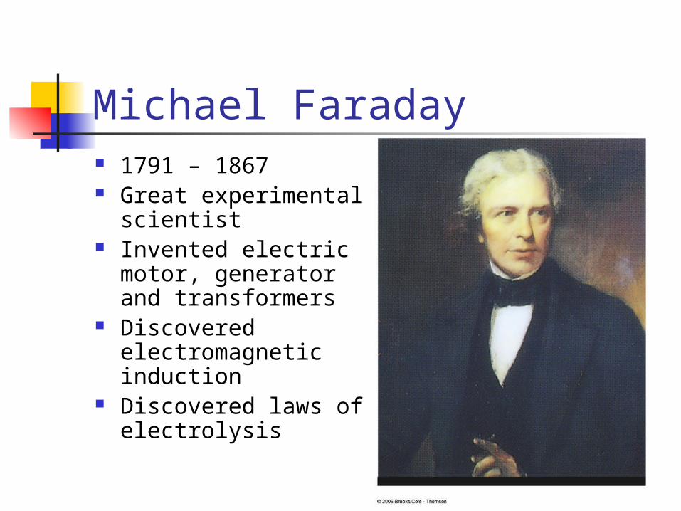
Michael Faraday 1791 – 1867 Great experimental
scientist Invented electric
motor, generator and transformers
Discovered electromagnetic induction
Discovered laws of electrolysis

Faraday’s Experiment – Set Up A current can be produced by a
changing magnetic field First shown in an experiment by Michael
Faraday A primary coil is connected to a battery A secondary coil is connected to an ammeter
Faraday’s Experiment The purpose of the secondary circuit is to
detect current that might be produced by the magnetic field
When the switch is closed, the ammeter reads a current and then returns to zero
When the switch is opened, the ammeter reads a current in the opposite direction and then returns to zero
When there is a steady current in the primary circuit, the ammeter reads zero
Faraday’s Conclusions An electrical current is produced by a
changing magnetic field The secondary circuit acts as if a source
of emf were connected to it for a short time
It is customary to say that an induced emf is produced in the secondary circuit by the changing magnetic field
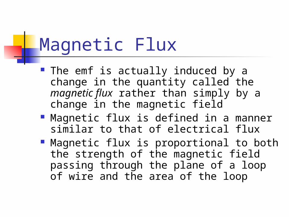
Magnetic Flux The emf is actually induced by a change
in the quantity called the magnetic flux rather than simply by a change in the magnetic field
Magnetic flux is defined in a manner similar to that of electrical flux
Magnetic flux is proportional to both the strength of the magnetic field passing through the plane of a loop of wire and the area of the loop

Magnetic Flux, 2 You are given a loop
of wire The wire is in a
uniform magnetic field
The loop has an area A
The flux is defined as ΦB = BA = B A cos θ
θ is the angle between B and the normal to the plane
B
Magnetic Flux, 3
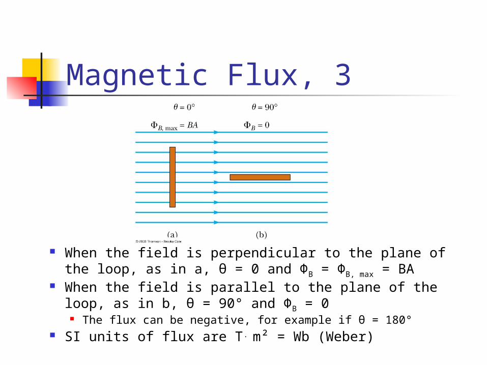
When the field is perpendicular to the plane of the loop, as in a, θ = 0 and ΦB = ΦB, max = BA
When the field is parallel to the plane of the loop, as in b, θ = 90° and ΦB = 0
The flux can be negative, for example if θ = 180° SI units of flux are T. m² = Wb (Weber)
Magnetic Flux, final The flux can be visualized with respect to
magnetic field lines The value of the magnetic flux is
proportional to the total number of lines passing through the loop
When the area is perpendicular to the lines, the maximum number of lines pass through the area and the flux is a maximum
When the area is parallel to the lines, no lines pass through the area and the flux is 0
Electromagnetic Induction –An Experiment
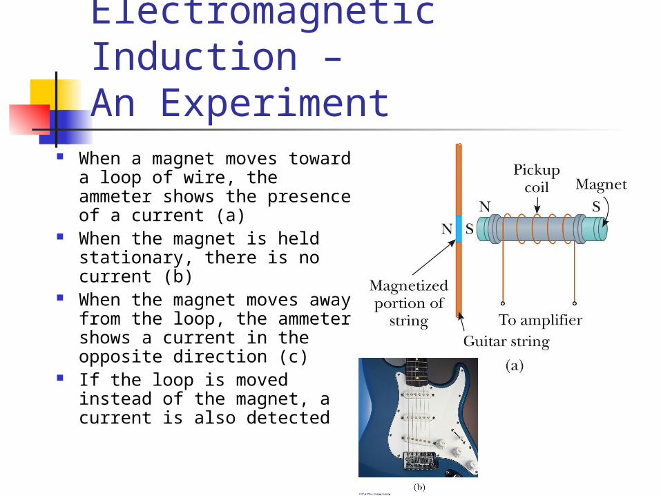
When a magnet moves toward a loop of wire, the ammeter shows the presence of a current (a)
When the magnet is held stationary, there is no current (b)
When the magnet moves away from the loop, the ammeter shows a current in the opposite direction (c)
If the loop is moved instead of the magnet, a current is also detected
Electromagnetic Induction – Results of the Experiment A current is set up in the circuit as
long as there is relative motion between the magnet and the loop The same experimental results are
found whether the loop moves or the magnet moves
The current is called an induced current because is it produced by an induced emf
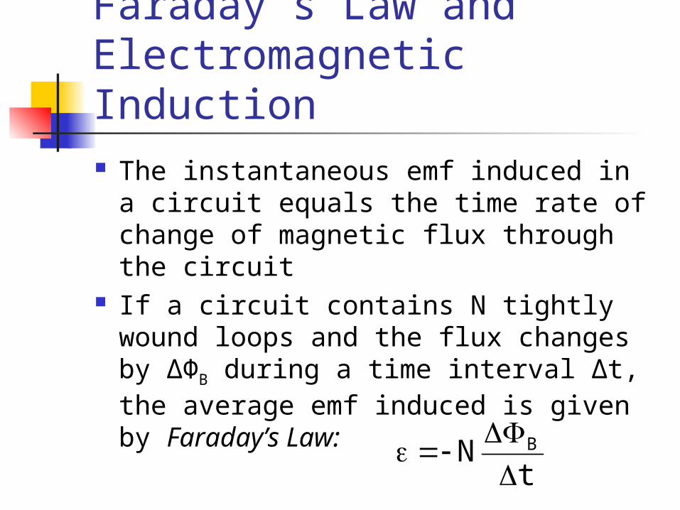
Faraday’s Law and Electromagnetic Induction The instantaneous emf induced in a
circuit equals the time rate of change of magnetic flux through the circuit
If a circuit contains N tightly wound loops and the flux changes by ΔΦB during a time interval Δt, the average emf induced is given by Faraday’s Law:
tN B

Faraday’s Law and Lenz’ Law The change in the flux, ΔΦB, can be
produced by a change in B, A or θ Since ΦB = B A cos θ
The negative sign in Faraday’s Law is included to indicate the polarity of the induced emf, which is found by Lenz’ Law
The current caused by the induced emf travels in the direction that creates a magnetic field with flux opposing the change in the original flux through the circuit
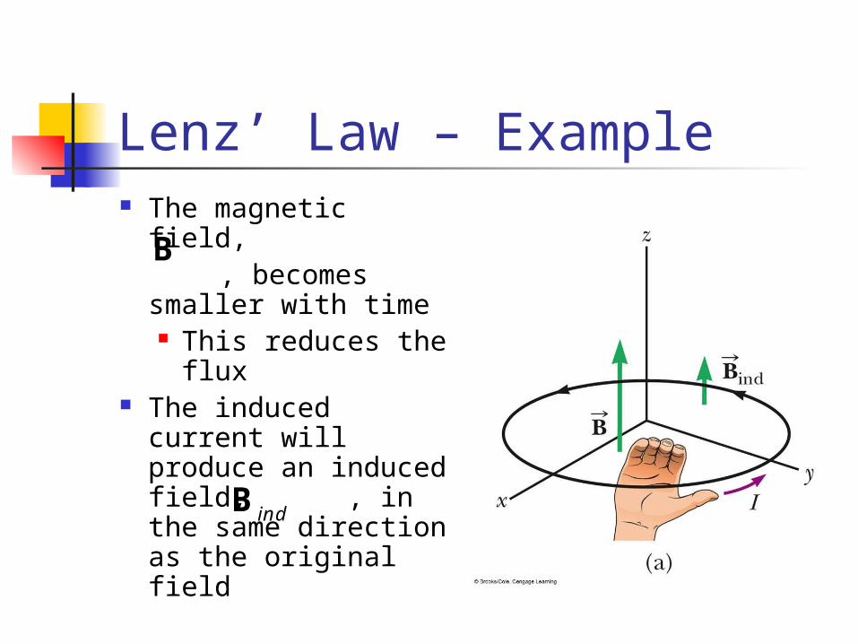
Lenz’ Law – Example The magnetic field, , becomes
smaller with time This reduces the
flux The induced
current will produce an induced field, , in the same direction as the original field
B
indB
Applications of Faraday’s Law – Ground Fault Interrupters
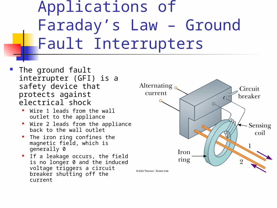
The ground fault interrupter (GFI) is a safety device that protects against electrical shock
Wire 1 leads from the wall outlet to the appliance
Wire 2 leads from the appliance back to the wall outlet
The iron ring confines the magnetic field, which is generally 0
If a leakage occurs, the field is no longer 0 and the induced voltage triggers a circuit breaker shutting off the current
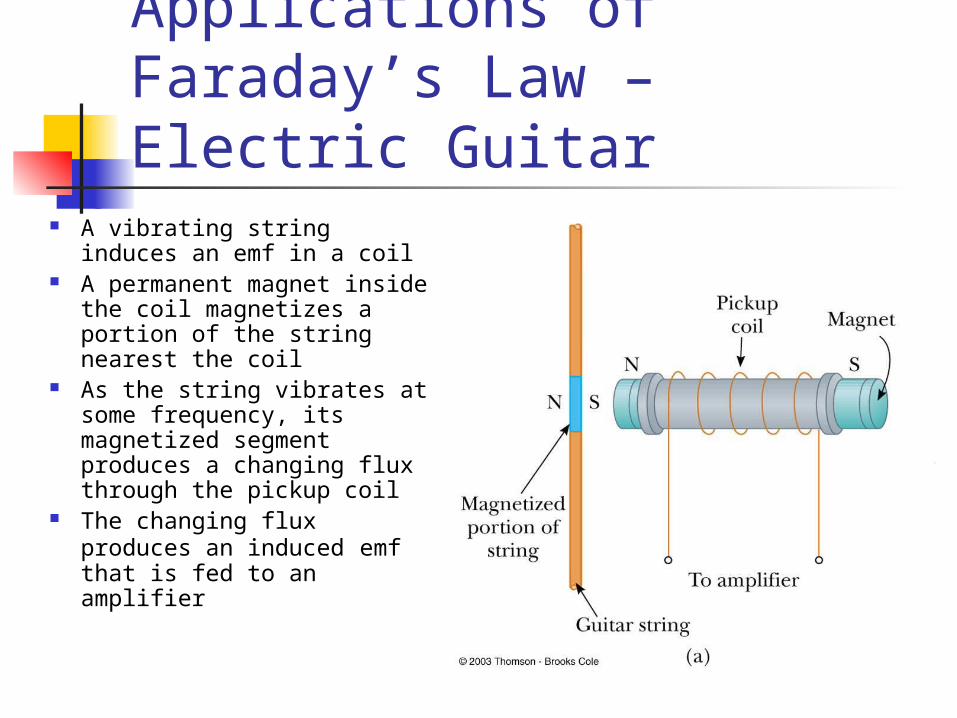
Applications of Faraday’s Law – Electric Guitar
A vibrating string induces an emf in a coil
A permanent magnet inside the coil magnetizes a portion of the string nearest the coil
As the string vibrates at some frequency, its magnetized segment produces a changing flux through the pickup coil
The changing flux produces an induced emf that is fed to an amplifier
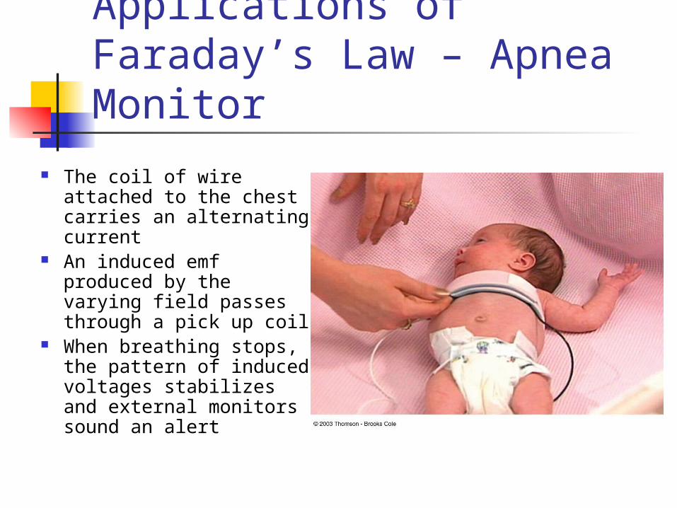
Applications of Faraday’s Law – Apnea Monitor
The coil of wire attached to the chest carries an alternating current
An induced emf produced by the varying field passes through a pick up coil
When breathing stops, the pattern of induced voltages stabilizes and external monitors sound an alert

Application of Faraday’s Law – Motional emf
A straight conductor of length ℓ moves perpendicularly with constant velocity through a uniform field
The electrons in the conductor experience a magnetic force
F = q v B The electrons tend to
move to the lower end of the conductor
Motional emf As the negative charges accumulate at the
base, a net positive charge exists at the upper end of the conductor
As a result of this charge separation, an electric field is produced in the conductor
Charges build up at the ends of the conductor until the downward magnetic force is balanced by the upward electric force
There is a potential difference between the upper and lower ends of the conductor
Motional emf, cont The potential difference between the
ends of the conductor can be found by ΔV = E l = B ℓ v The upper end is at a higher potential than
the lower end A potential difference is maintained
across the conductor as long as there is motion through the field If the motion is reversed, the polarity of the
potential difference is also reversed
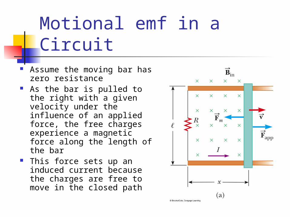
Motional emf in a Circuit Assume the moving bar has
zero resistance As the bar is pulled to the
right with a given velocity under the influence of an applied force, the free charges experience a magnetic force along the length of the bar
This force sets up an induced current because the charges are free to move in the closed path
Motional emf in a Circuit, cont
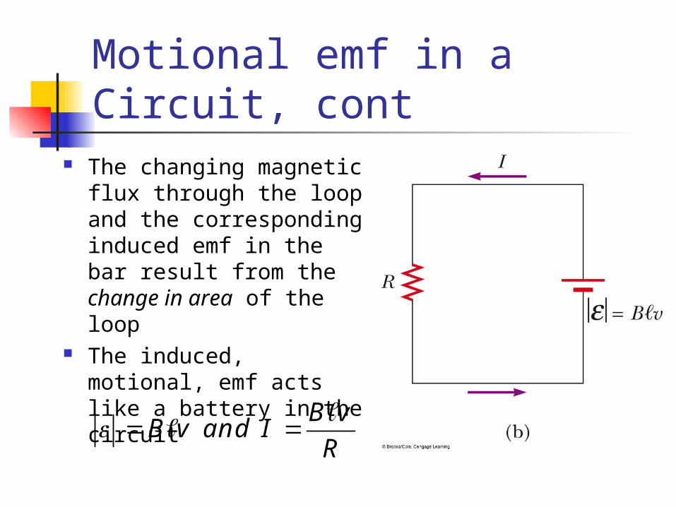
The changing magnetic flux through the loop and the corresponding induced emf in the bar result from the change in area of the loop
The induced, motional, emf acts like a battery in the circuit
B vB v and I
R

Lenz’ Law Revisited – Moving Bar Example
As the bar moves to the right, the magnetic flux through the circuit increases with time because the area of the loop increases
The induced current must be in a direction such that it opposes the change in the external magnetic flux
Lenz’ Law, Bar Example, cont The flux due to the external field is
increasing into the page The flux due to the induced current
must be out of the page Therefore the current must be
counterclockwise when the bar moves to the right

Lenz’ Law, Bar Example, final
The bar is moving toward the left
The magnetic flux through the loop is decreasing with time
The induced current must be clockwise to to produce its own flux into the page
Lenz’ Law Revisited, Conservation of Energy Assume the bar is moving to the right Assume the induced current is clockwise
The magnetic force on the bar would be to the right
The force would cause an acceleration and the velocity would increase
This would cause the flux to increase and the current to increase and the velocity to increase…
This would violate Conservation of Energy and so therefore, the current must be counterclockwise
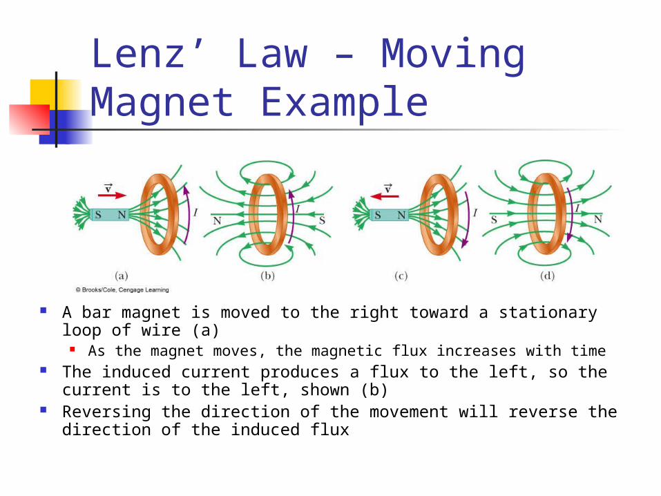
Lenz’ Law – Moving Magnet Example
A bar magnet is moved to the right toward a stationary loop of wire (a)
As the magnet moves, the magnetic flux increases with time The induced current produces a flux to the left, so the current is to
the left, shown (b) Reversing the direction of the movement will reverse the direction
of the induced flux
Lenz’ Law, Final Note When applying Lenz’ Law, there
are two magnetic fields to consider The external changing magnetic field
that induces the current in the loop The magnetic field produced by the
current in the loop
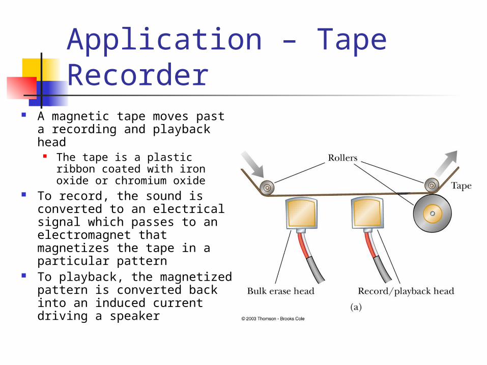
Application – Tape Recorder
A magnetic tape moves past a recording and playback head
The tape is a plastic ribbon coated with iron oxide or chromium oxide
To record, the sound is converted to an electrical signal which passes to an electromagnet that magnetizes the tape in a particular pattern
To playback, the magnetized pattern is converted back into an induced current driving a speaker

Generators Alternating Current (AC) generator
Converts mechanical energy to electrical energy
Consists of a wire loop rotated by some external means
There are a variety of sources that can supply the energy to rotate the loop
These may include falling water, heat by burning coal to produce steam
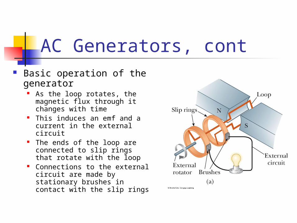
AC Generators, cont Basic operation of the
generator As the loop rotates, the
magnetic flux through it changes with time
This induces an emf and a current in the external circuit
The ends of the loop are connected to slip rings that rotate with the loop
Connections to the external circuit are made by stationary brushes in contact with the slip rings
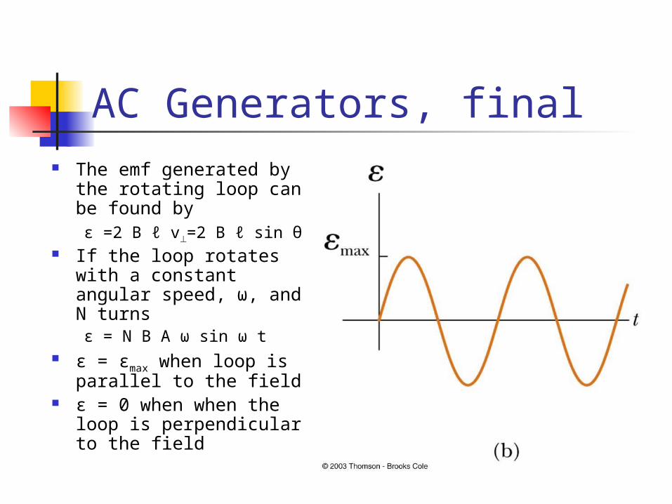
AC Generators, final The emf generated by
the rotating loop can be found byε =2 B ℓ v=2 B ℓ sin θ
If the loop rotates with a constant angular speed, ω, and N turnsε = N B A ω sin ω t
ε = εmax when loop is parallel to the field
ε = 0 when when the loop is perpendicular to the field
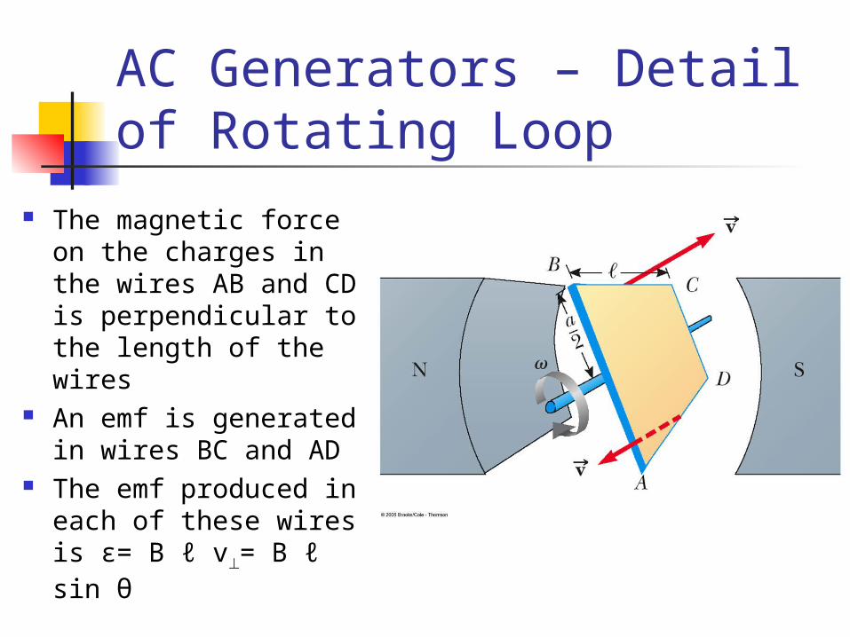
AC Generators – Detail of Rotating Loop
The magnetic force on the charges in the wires AB and CD is perpendicular to the length of the wires
An emf is generated in wires BC and AD
The emf produced in each of these wires is ε= B ℓ v= B ℓ sin θ
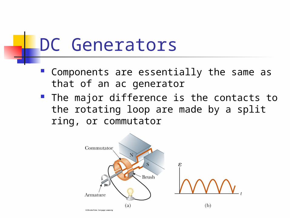
DC Generators Components are essentially the same as that
of an ac generator The major difference is the contacts to the
rotating loop are made by a split ring, or commutator

DC Generators, cont The output voltage
always has the same polarity
The current is a pulsing current
To produce a steady current, many loops and commutators around the axis of rotation are used
The multiple outputs are superimposed and the output is almost free of fluctuations
Motors Motors are devices that convert
electrical energy into mechanical energy A motor is a generator run in reverse
A motor can perform useful mechanical work when a shaft connected to its rotating coil is attached to some external device
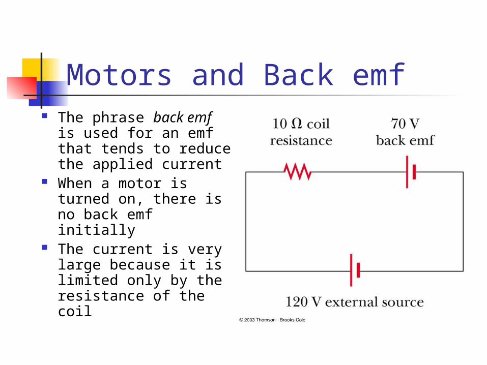
Motors and Back emf The phrase back emf
is used for an emf that tends to reduce the applied current
When a motor is turned on, there is no back emf initially
The current is very large because it is limited only by the resistance of the coil

Motors and Back emf, cont As the coil begins to rotate, the induced
back emf opposes the applied voltage The current in the coil is reduced The power requirements for starting a
motor and for running it under heavy loads are greater than those for running the motor under average loads
Self-inductance Self-inductance occurs when the
changing flux through a circuit arises from the circuit itself
As the current increases, the magnetic flux through a loop due to this current also increases
The increasing flux induces an emf that opposes the change in magnetic flux
As the magnitude of the current increases, the rate of increase lessens and the induced emf decreases
This opposing emf results in a gradual increase of the current
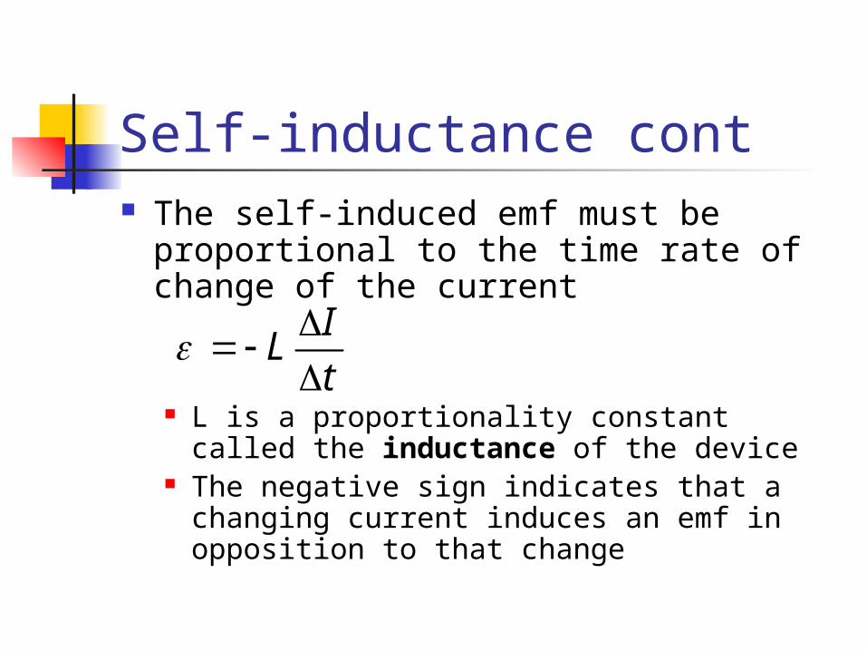
Self-inductance cont The self-induced emf must be
proportional to the time rate of change of the current
L is a proportionality constant called the inductance of the device
The negative sign indicates that a changing current induces an emf in opposition to that change
IL
t
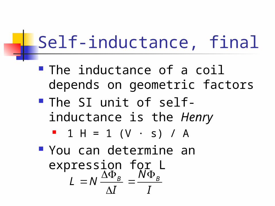
Self-inductance, final The inductance of a coil depends
on geometric factors The SI unit of self-inductance is the
Henry 1 H = 1 (V · s) / A
You can determine an expression for L
B BNL N
I I
Joseph Henry 1797 – 1878 First director of the
Smithsonian First president of the
Academy of Natural Science First to produce an electric
current with a magnetic field Improved the design of the
electro-magnet and constructed a motor
Discovered self-inductance
Inductor in a Circuit Inductance can be interpreted as a
measure of opposition to the rate of change in the current Remember resistance R is a measure of
opposition to the current As a circuit is completed, the current
begins to increase, but the inductor produces an emf that opposes the increasing current Therefore, the current doesn’t change from 0
to its maximum instantaneously

RL Circuit When the current
reaches its maximum, the rate of change and the back emf are zero
The time constant, , for an RL circuit is the time required for the current in the circuit to reach 63.2% of its final value
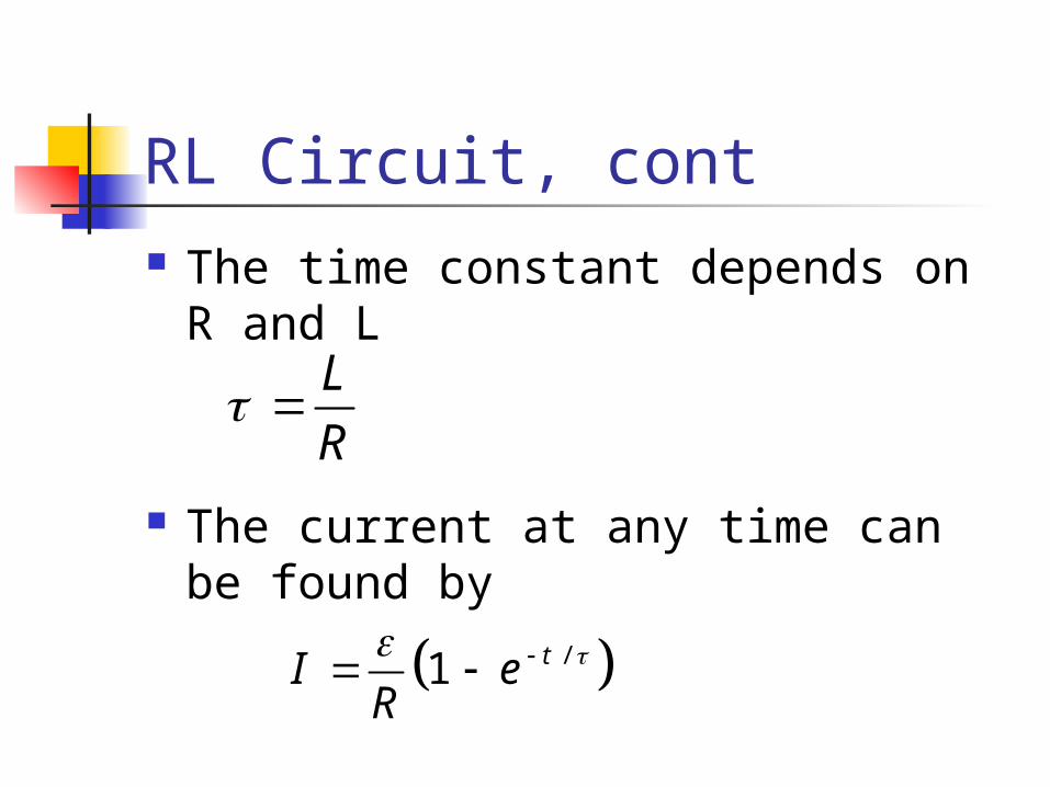
RL Circuit, cont The time constant depends on R
and L
The current at any time can be found by
LR
/1 tI eR

Energy Stored in a Magnetic Field The emf induced by an inductor
prevents a battery from establishing an instantaneous current in a circuit
The battery has to do work to produce a current This work can be thought of as energy
stored by the inductor in its magnetic field PEL = ½ L I2