chapter 20 show commands - ftp.hp.comftp.hp.com/pub/networking/software/59692339_20.pdfto view the...
TRANSCRIPT

Chapter 20Show Commands
show appletalk arpDisplays the ARP Table for the AppleTalk routing protocol.
EXAMPLE:
Index Node Address Mac Address Port
1 10.30 00e0.5200.0000 1
Syntax: show appletalk arp
Possible values: N/A
Default value: N/A
show appletalk cacheDisplays the forwarding table for the AppleTalk routing protocol. You can clear this cache by entering the CLI command, clear appletalk cache.
EXAMPLE:
HP9300> show appletalk cache
Total number of cache entries: 8
D:Dynamic P:Permanent F:Forward U:Us W:Wait ARP K:Drop
Destination Next Hop MAC Type Fid Vlan
1 6499.193 6300.22 0000.c541.bc71 DF 9 1
2 6401.0 6300.22 0000.c541.bc71 DF 9 1
3 6300.177 0.0 0000.0000.0000 PU 0
4 6300.22 0.0 0000.c541.bc71 DF 9 1
5 450.0 0.0 0000.0000.0000 PU 0
6 400.0 0.0 0000.0000.0000 PU 0
7 6300.0 0.0 0000.0000.0000 PU 0
8 450.177 0.0 0000.0000.0000 PU 0
Syntax: show appletalk cache
Possible values: N/A
Default value: N/A
20 - 1

Command Line Interface Reference
show appletalk globalsDisplays the global configuration parameters for the AppleTalk routing protocol.
EXAMPLE:
HP9300> show appletalk globals
AppleTalk Routing Global Settings:
enabled: Routing
disabled: Glean Packets
rtmp-update-interval: 10
zip-query-interval:10, arp-retransmit-interval: 1, arp-retransmit-count: 2
QOS Priority 0 Sockets: 1 - 254
QOS Priority 1 Sockets: None
Syntax: show appletalk globals
show appletalk interfaceDisplays the AppleTalk configuration for an individual interface or all interfaces.
EXAMPLE:
To view the configuration for all interfaces, enter show appletalk interface, as shown in the example below. To view the configuration of a specific interface, enter show appletalk interface ethernet <portnum>. To view the configuration of a virtual interface (VE), enter show appletalk interface ve <num>.
HP9300> show appletalk interfaceInterface Ethernet 15 port state: UP routing: Enabled operation mode:Seed Router address: 100.50, cable-range: 100 - 100 arp-age 10 Zone Filter List: Action: Permit Zone name: sales, no RTMP Filtering Additional Zones Action: Permit, No RTMP FilteringInterface Ethernet 16 port state: DOWNrouting: Disabled operation mode:Routing not enabled. address: 200.50, cable-range: 200 - 400 arp-age 10 Zone Filter List: No zone filters are configured.Interface Ve 3 members: ethe 1 to 3 active: ethe 1 port state: UP routing: Enabled operation mode: Seed Router address: 200.50, cable-range: 200 - 200 arp-age 10 Zone List: Finance Zone Filter List: No zone filters are configured.
Syntax: show appletalk interface [ethernet <portnum> | ve <num>]
The ethernet <portnum> parameter lets you specify specific interface.
The ve <num> parameter lets you specify a virtual interface (VE).
Possible values: N/A
Default value: N/A
20 - 2

Show Commands
show appletalk routeDisplays the AppleTalk routing table.
Up to 512 route entries can be stored in the routing table for a system with at least 32 MB of memory.
You can clear learned routes stored in the routing table by entering the clear appletalk route command.
EXAMPLE:
HP9300> show appletalk route
Index Cable Range Next Hop Distance State Port
1 6300 - 6400 0.0 0 0 2
2 6401 - 6500 6300.22 1 0 2
3 400 - 499 0.0 0 0 1
4 500 - 599 450.10 1 0 1
5 600 - 699 450.10 2 0 1
6 200 - 300 450.10 2 0 1
7 1000 - 1100 450.10 2 0 1
8 1200 - 1299 450.10 2 0 1
9 7000 - 8000 450.10 1 0 1
NOTE: Please note the following regarding the information displayed in the AppleTalk routing table:
Index: Identifies the entry.
Cable Range: Shows the network numbers to which the route information applies.
Next Hop: Shows the address of the next hop router to which packets for that destination will be sent.
Distance: Indicates the number of hops away that the destination is from this router
State: Indicates the state of the entry. The possible states that may be displayed in this field are listed below with the numerical value that will appear in the table:
• Good route: 0
• Suspect route: 2
• Bad Route: 4
Port: References the port number upon which the next hop router is found.
Syntax: show appletalk route
Possible values: N/A
Default value: N/A
show appletalk trafficDisplays statistical information for RTMP, ZIP, AEP, DDP and AARP packets.
EXAMPLE:
HP9300> show appletalk traffic
RTMP Statistics:
Received: 16038, Transmitted: 16032, Filtered: 0
ZIP Statistics:
Query Received:16, Transmitted:6, GZL Received: 2, Transmitted: 1
20 - 3

Command Line Interface Reference
NetInfo Statistics:
Received: 10 , Reply:8
AEP Statistics:
Request Received: 0, Request Transmitted: 0
Reply Received: 0, Reply Transmitted: 0
DDP Statistics:
Received: 55468, Transmitted: 55445, Forwarded: 39372
In-Delivered: 16092, Dropped-No-Route:0, Dropped-Bad-Hop-Counts: 0
Dropped-Other-Reasons: 0
AARP Statistics:
Received: 14, Transmitted: 22
NOTE: Note the following regarding the information displayed in the AppleTalk traffic table.
RTMP Statistics: Provides a count of all RTMP packets received, transmitted and filtered on the router.
ZIP statistics: Provides a count of requests for zone information (Recv. Query) the system receives as well as a count of those ZIP queries made to other routers (Query, Transmitted). The ’Recv GZL’ count lists those Get Zone List requests received from other routers and the ’Transmitted’ field lists those GZL requests transmitted to other routers.
NetInfo Statistics: The received and reply values of this field refer to the number of zone and network number requests made and received by the router.
AEP Statistics: Provides a count of those AppleTalk Echo Protocol (pings) requests received or transmitted and a count of the replies received or transmitted.
DDP Statistics: Displays the total count of those DDP packets transmitted, received and forwarded from the router; those packets received and forwarded up the AppleTalk protocol stack (in-delivered) and those packets dropped due to an unknown route (no-route), those packets that exceeded maximum hop count and those that were dropped due to unknown MAC address (other-reasons).
AARP Statistics: Displays the total count of those AARP packets received and transmitted by the router.
Syntax: show appletalk traffic
Possible values: N/A
Default value: N/A
show appletalk zoneDisplays the network numbers and zones learned on the network. You can clear all information stored in the zone table by entering the clear appletalk route command.
EXAMPLE:
HP9300> show appletalk zone
Index Cable Range Zonename
1 6300 - 6400 QA
2 6300 - 6400 QARouter
3 6401 - 6500 QA1
4 6401 - 6500 QALab2
5 400 - 499 account
6 1200 - 1299 sales
20 - 4

Show Commands
7 1000 - 1100 engineering
8 1000 - 1100 HPnetwork
9 1000 - 1100 HPnetworks1
10 200 - 300 marketing
11 600 - 699 management
12 500 - 599 gigabit
13 7000 - 8000 gatethernet0
Syntax: show appletalk zone
Possible values: N/A
Default value: N/A
show arpDisplays the ARP cache of the switch or routing switch. For switches, the show arp command will not display the ’type’ column, but will display a VLAN ID column.
EXAMPLE:
HP9300# show arp
Total number of ARP entries: 5
IP Address MAC Address Type Age Port
1 207.95.6.102 0800.5afc.ea21 Dynamic 0 6
2 207.95.6.18 00a0.24d2.04ed Dynamic 3 6
3 207.95.6.54 00a0.24ab.cd2b Dynamic 0 6
4 207.95.6.101 0800.207c.a7fa Dynamic 0 6
5 207.95.6.211 00c0.2638.ac9c Dynamic 0 6
Syntax: show arp [ethernet <portnum> | mac-address <xxxx.xxxx.xxxx> [<mask>] | <ip-addr> [<ip-mask>]] [<num>]
Specify the MAC address mask as “f”s and “0”s, where “f”s are significant bits. Specify IP address masks in standard decimal mask format (for example, 255.255.0.0).
The optional <num> parameter lets you display the table beginning with a specific entry number.
Possible values: N/A
EXAMPLE:Default value: N/A
Here are some examples of how to use these commands.
The following command displays all ARP entries for MAC addresses that begin with “abcd”:
HP9300# show arp mac-address a.b.c.d ffff.0000.0000
The following command displays all IP address entries for IP addresses that begin with "209.157":
HP9300# show arp 209.157.0.0 255.255.0.0
show chassisDisplays the presence and status of power supplies and fans in the chassis.
EXAMPLE:
HP9300# show chassis
power supply 1 ok
power supply 2 not present
20 - 5

Command Line Interface Reference
fan 1 ok
fan 2 ok
fan 3 ok
fan 4 ok
power supply 3 ok
power supply 4 not present
Syntax: show chassis
Possible values: N/A
Default value: N/A
show clockDisplays the current settings for the on-board time counter and Simple Network Time Protocol (SNTP) clock, if configured.
EXAMPLE:
HP9300# show clock
Syntax: show clock [detail]
Possible values: N/A
Default value: N/A
show configurationLists the operating configuration of an HP switch or routing switch. This command allows you to check configuration changes before saving them to flash.
EXAMPLE:
HP9300# show configuration
Syntax: show configuration
Possible values: N/A
Default value: N/A
show defaultDisplays the defaults for system parameters.
If you specify "default" but not the optional "values", the default states for parameters that can either be enabled or disabled are displayed. If you also specify "values", the default values for parameters that take a numeric value are displayed.
You can reconfigure the system parameters displayed by the “values” option using the system-max command. See “system-max” on page 6-61.
EXAMPLE:
Here are some examples of the information displayed by these commands. The first example shows the information displayed by the show default command on an HP 9308M routing switch.
NOTE: If the information scrolls off the screen, you can enable page-display mode. See “page-display” on page 5-13.
20 - 6

Show Commands
HP9300# show default
spanning tree disabled
auto sense port speed port untagged port flow control on
no username assigned no password assigned boot sys flash primary
system traps enabled sntp disabled radius disabled
rip disabled ospf disabled bgp disabled
when ip routing enabled :
ip irdp enabled ip load-sharing enabled ip proxy arp enabled
ip rarp enabled ip bcast forward enabled
dvmrp disabled pim/dm disabled
vrrp disabled srp disabled
when rip enabled :
rip type:v2 only rip poison rev enabled
ipx disabled appletalk disabled
EXAMPLE:
The following example shows the command output when you use the values option on an HP 9304M or HP 9308M routing switch.
HP9300# show default values
sys log buffers:50 mac age time:300 sec telnet sessions:5
ip arp age:20 min bootp relay max hops:4 ip ttl:64 hops
ip addr per intf:24
when multicast enabled :
igmp group memb.:140 sec igmp query:60 sec
when ospf enabled :
ospf dead:40 sec ospf hello:10 sec ospf retrans:5 sec
ospf transit delay:1 sec
when bgp enabled :
bgp local pref.:100 bgp keep alive:60 sec bgp hold:180 sec
bgp metric:10 bgp local as:1 bgp cluster id:0
bgp ext. distance:20 bgp int. distance:200 bgp local distance:200
20 - 7

Command Line Interface Reference
System Parameters Default Maximum
arp 4000 16000
atalk-route 512 3072
atalk-zone-port 64 255
atalk-zone-sys 255 1024
dvmrp 2048 32000
igmp 255 1024
ip-cache 16000 64000
ip-filter-port 32 256
ip-filter-sys 64 2048
ipx-forward-filter 32 256
ipx-rip-entry 2048 16384
ipx-rip-filter 32 256
ipx-sap-entry 4096 16384
ipx-sap-filter 32 256
l3-vlan 32 1024
ip-qos-session 128 32000
mac 8000 64000
ip-route 10000 200000
ip-static-route 64 1024
vlan 8 4096
mac-filter-port 16 256
mac-filter-sys 32 512
Syntax: show default [values]
Possible values: N/A
Default value: N/A
show flashDisplays the version of the software image saved in the primary and secondary flash of an HP switch or routing switch.
EXAMPLE:
HP9300# show flash
Syntax: show flash
Possible values: N/A
Default value: N/A
show interfacesDisplays information about interfaces on the HP switch or routing switch, including their state, duplex mode, STP state, priority and MAC address.
20 - 8

Show Commands
EXAMPLE:
HP9300# show interfaces ethernet 4/11FastEthernet4/11 is up, line protocol is up Hardware is FastEthernet, address is 00e0.52f0.4f6a (bia 00e0.52f0.4f6a) Configured speed auto, actual 100Mbit, configured duplex fdx, actual fdx Member of L2 VLAN ID 10, port is untagged, port state is FORWARDING STP configured to OFF, priority is level0, flow control enabled mirror disabled, monitor disabled Not member of any active trunks Not member of any configured trunks No port name Internet address is 209.157.22.241/24, MTU 1500 bytes, encapsulation ethernet 5 minute input rate: 8 bits/sec, 0 packets/sec, 0.00% utilization 5 minute output rate: 0 bits/sec, 0 packets/sec, 0.00% utilization 1685 packets input, 180006 bytes, 0 no buffer Received 91 broadcasts, 0 runts, 0 giants 0 input errors, 0 CRC, 0 frame, 0 ignored 31 multicast 2018 packets output, 1040885 bytes, 0 underruns 0 output errors, 0 collisions
Syntax: show interfaces [ethernet <portnum>] | [loopback <num>] | [slot <slot-num>] | [ve <num>]
Possible values: N/A
Default value: N/A
show interfaces briefShows a summary of Layer 2 information for all interfaces.
EXAMPLE:
HP9300# show interfaces briefPort Link State Dupl Speed Trunk Tag Priori MAC Name1/1 Down None None None None No level0 00e0.52f0.4f001/2 Down None None None None No level0 00e0.52f0.4f011/3 Down None None None None No level0 00e0.52f0.4f021/4 Down None None None None No level0 00e0.52f0.4f031/5 Down None None None None No level0 00e0.52f0.4f041/6 Down None None None None No level0 00e0.52f0.4f051/7 Down None None None None No level0 00e0.52f0.4f061/8 Down None None None None No level0 00e0.52f0.4f07
Syntax: show interfaces [ethernet <portnum>] | [loopback <num>] | [slot <slot-num>] | [ve <num>] | [brief]
Possible values: N/A
Default value: N/A
show ipFor HP switches, this command displays the switch IP address and mask, its default router, the IP address of a TFTP server where configuration or image files are stored, if defined; and the file names of image and configuration files saved on that TFTP server.
For HP routing switches, this command displays the global parameters for IP—specifically, router ID, IP TTL, ARP age values as well as all protocols and IP features enabled on the router. This command also displays all active filters.
20 - 9

Command Line Interface Reference
EXAMPLE:
Global Settings
ttl: 64, arp-age: 10, bootp-relay-max-hops: 4
router-id : 10.1.1.1
enabled : UDP-Broadcast-Forwarding IRDP Proxy-ARP RARP RIP VRRP
disabled: BGP4 Load-Sharing RIP-Redist OSPF DVMRP SRP
Policies
Index Action Source Destination Protocol Port Operator
1 deny 209.157.22.34 209.157.22.26 tcp http =
64 permit any any
Syntax: show ip
Possible values: N/A
Default value: N/A
show ip access-listsDisplays the configured IP Access Control Lists (ACLs).
show ip as-path-access-listsDisplays the configured IP AS-path ACLs, used for BGP4 filtering.
show ip bgp <ip-addr>Displays routes that match a specified address and mask.
EXAMPLE:
To display only the routes for network 3.3.0.0/16:
HP9300# show ip bgp 3.3.0.0/16 longer Number of BGP Routes matching display condition : 2Status codes: s suppressed, * valid, > best, i internalOrigin codes: i - IGP, e - EGP, ? - incomplete Network Next Hop Metric LocPrf Weight Path*> 3.3.3.0 207.95.6.101 0 100 0 2 ?*> 3.3.4.0 207.95.6.101 0 100 0 2 ?
This example shows all the routes for networks beginning with 3.3. The mask value and longer parameter specify the range of network addresses to be displayed. In this example, all routes within the range 3.3.0.0 – 3.3.255.255 are listed.
Syntax: show ip bgp <ip-addr>/<mask-bits> [longer]
Possible values: see above
Default value: N/A
show ip bgp attribute-entriesShows information entries in a routing switch’s BGP4 route attributes table. The route-attribute entries table lists the sets of BGP4 attributes stored in the routing switch’s memory. Each set of attributes is unique and can be associated with one or more routes. In fact, the routing switch typically has fewer route attribute entries than routes.
See the “Configuring BGP4” chapter of the Advanced Configuration and Management Guide for information about the fields in this display.
20 - 10

Show Commands
EXAMPLE:
HP9300# show ip bgp attribute-entries
Total number of BGP Attribute Entries: 7753
1 Next Hop :192.168.11.1 Metric :0 Origin:IGP
Originator:0.0.0.0 Cluster List:None
Aggregator:AS Number :0 Router-ID:0.0.0.0 Atomic:FALSE
Local Pref:100 Communities:Internet
AS Path :(65002) 65001 4355 2548 3561 5400 6669 5548
2 Next Hop :192.168.11.1 Metric :0 Origin:IGP
Originator:0.0.0.0 Cluster List:None
Aggregator:AS Number :0 Router-ID:0.0.0.0 Atomic:FALSE
Local Pref:100 Communities:Internet
AS Path :(65002) 65001 4355 2548
remaining 7751 entries not shown...
Syntax: show ip bgp attribute-entries
Possible values: N/A
Default value: N/A
show ip bgp neighborsShows information about a routing switch’s BGP4 neighbors (peer BGP4 routers). See the “Configuring BGP4” chapter of the Advanced Configuration and Management Guide for information about the fields in this display.
EXAMPLE:
HP9300# show ip bgp neighbors 192.168.11.1Total number of BGP Neighbors: 3
IP Address Remote AS EBGP/IBGP State1 192.168.11.1 65001 Confed_EBGP ESTABLISHED Keep Alive Time Hold Time Advertisement Interval 0 0 5 Message Sent Message Received Keep Alive 3 3 Update 19 28270 Notifications 0 0 Open 3 3 Last Connection Reset Reason:Port State Down Notification Message Error Code Received:Unspecified Notification Message Error SubCode Received:Not Applicable Notification Message Error Code Transmitted:Unspecified Notification Message Error SubCode Transmitted:Not Applicable
TCP Connection state: ESTABLISHED Local host: 192.168.11.1, Local Port: 8180 Remote host: 192.168.11.2, Remote Port: 179 ISentSeq: 710279168 SendNext: 710279383 TotUnAck: 0 SendWnd: 16384 TotSent: 215 ReTrans: 171 IRcvSeq: 0 RcvNext: 462 RcvWnd: 16384 TotalRcv: 462 RcvQue: 0 SendQue: 0
20 - 11
Command Line Interface Reference
Syntax: show ip bgp neighbor [<ip-addr> [advertised-routes] [last-packet-with-error] [attribute-entries] [received-routes] [routes-summary]]
The <ip-addr> option lets you narrow the scope of the command to a specific neighbor.
The advertised-routes option displays only the routes that the routing switch has advertised to the neighbor during the current BGP4 neighbor session.
The last-packet-with-error displays a hexadecimal dump of the first 400 bytes of the last packet received from the neighbor that contained an error.
The attribute-entries option shows the attribute-entries associated with routes received from the neighbor.
The received-routes option lists the routes received in UPDATE messages from the neighbor.
The routes-summary option displays a summary of the following information:
• Number of routes received from the neighbor
• Number of routes accepted by this routing switch from the neighbor
• Number of routes this routing switch filtered out of the UPDATES received from the neighbor and did not accept
• Number of routes advertised to the neighbor
• Number of attribute entries associated with routes received from or advertised to the neighbor.
Possible values: see above
Default value: information for all neighbors is displayed
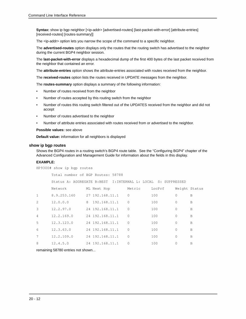
show ip bgp routesShows the BGP4 routes in a routing switch’s BGP4 route table. See the “Configuring BGP4” chapter of the Advanced Configuration and Management Guide for information about the fields in this display.
EXAMPLE:
HP9300# show ip bgp routes
Total number of BGP Routes: 58788
Status A: AGGREGATE B:BEST I:INTERNAL L: LOCAL S: SUPPRESSED
Network ML Next Hop Metric LocPrf Weight Status
1 8.9.253.160 27 192.168.11.1 0 100 0 B
2 12.0.0.0 8 192.168.11.1 0 100 0 B
3 12.2.97.0 24 192.168.11.1 0 100 0 B
4 12.2.169.0 24 192.168.11.1 0 100 0 B
5 12.3.123.0 24 192.168.11.1 0 100 0 B
6 12.3.63.0 24 192.168.11.1 0 100 0 B
7 12.2.109.0 24 192.168.11.1 0 100 0 B
8 12.4.5.0 24 192.168.11.1 0 100 0 B
remaining 58780 entries not shown...
20 - 12

Show Commands
Here is an example of the information displayed when you use the detail option. In this example, the information for one route is shown.
HP9300# show ip bgp routes detail
Total number of BGP Routes: 388
Status A: AGGREGATE B:BEST I:INTERNAL L: LOCAL S: SUPPRESSED
Network MaskLen Next Hop Metric LocPrf Weight
1 12.2.97.0 24 192.168.11.1 0 100 0
Originator Atomic AGGREGATION-ID AS Cluster List
0.0.0.0 FALSE 0.0.0.0 0 None
Origin Status Route Tag Communities
IGP B 00000000 Internet
AS Path : (65002) 65001 4355 2548 7018 10656
remaining 387 entries not shown...
Syntax: show ip bgp routes <num> [cidr-only] [community <num> | no-export | no-advertise | internet | local-as] [community-list <num>] [detail <option>] [filter-list <num, num,...>] [network <ip-addr>][regular-expression <value>]
The <num> option specifies the table entry with which you want the display to start. For example, if you want to list entries beginning with table entry 100, specify 100.
The cidr-only option lists only the routes that do not have a mask length of 8, 16, or 24bits (the standard Class-A, -B, and -C sub-net mask lengths).
The community option lets you display routes for a specific community. You can specify no-export, no-advertise, internet, or a private community number. You can specify the community number as either two five-digit integer values of up to 1– 65535, separated by a colon (for example, 12345:6789) or a single long integer value.
The local-as parameter displays BGP4 routes that have the LOCAL_AS community type.
The community-list option lets you display routes that match a specific community filter.
The detail option lets you display greater detail for one of the other options.
The filter-list option displays routes that match a specific address filter list.
The network option displays routes for a specific network.
The regular-expression option filters the display based on a regular expression. See the “Configuring BGP4” chapter of the Advanced Configuration and Management Guide.
Possible values: see above
Default value: all routes are displayed
show ip bgp summaryShows a summary of BGP4 configuration information for a routing switch. See the “Configuring BGP4” chapter of the Advanced Configuration and Management Guide for information about the fields in this display.
EXAMPLE:
HP9300# show ip bgp summary
BGP4 Summary Local AS number : 64512 Confederation Identifier : 10 Confederation Peers : 64512 64513
20 - 13

Command Line Interface Reference
Maximum Number of Attribute Entries Supported :10000 Maximum Number of Routes Supported : 60000 Maximum Number of Neighbors Supported : 3 Maximum Number of Paths Supported for Load Sharing : 1 Number of Routes Installed : 58756 Number of Attribute Entries Installed : 7750
Neighbor Address AS# State StateChangeTime RtReceived RtInstalled RtSent 192.168.11.1 64512 ESTAB 0 :0 :43 :54 65871 65871 0 192.168.88.28 64512 ESTAB 0 :2 :26 :43 1 1 65875 192.168.199.1 64513 ESTAB 0 :0 :48 :5 0 0 65875
Syntax: show ip bgp summary
Possible values: N/A
Default value: N/A
show ip cacheDisplays the IP host table showing indices to MAC addresses and the IP address of the next hop for HP routing switches.
This command is not supported on HP switches.
EXAMPLE:
HP9300# show ip cache
Total number of cache entries: 243
D:Dynamic P:Permanent F:Forward U:Us C:Complex Filter
W:Wait ARP I:ICMP Deny K:Drop R:Fragment S:Snap Encap
IP Address Next Hop MAC Type Fid 1 207.95.95.1 0.0.0.0 0000.0000.0000 PU 0
2 111.111.100.111 0.0.0.0 0000.0000.0000 PU 0
3 207.95.45.1 0.0.0.0 0000.0000.0000 PU 0
4 207.195.1.255 0.0.0.0 0000.0000.0000 PU 0
5 207.95.133.255 0.0.0.0 0000.0000.0000 PU 0
. . . [entries 6-242 not shown]
243 207.95.42.1 0.0.0.0 0000.0000.0000 PU 0
Syntax: show ip cache [<ip-addr>] | [<num>]
The optional <num> parameter lets you display the table beginning with a specific entry number.
Possible values: N/A
Default value: N/A
show ip community-access-listsDisplays the configured IP community ACLs, which are used for BGP4 filtering.
show ip dvmrpDisplays the global and interface settings for DVMRP on an HP routing switch.
This command is not supported on HP switches.
20 - 14

Show Commands
EXAMPLE:
HP9300# show ip dvmrp
Global Settings
prune age: 180, neighbor timeout: 40
probe interval: 10, report interval: 60
route expire interval: 200, route discard interval: 340
triggered update interval: 5, graft retransmit interval: 10
Interface Ethernet 1
TTL Threshold: 1 Metric: 1
Local Address: 192.094.005.001
[. . . ]
Interface Ethernet 16
TTL Threshold: 1 Metric: 1
Local Address: 193.095.016.001
Syntax: show ip dvmrp
Possible values: N/A
Default value: N/A
show ip dvmrp flowcacheDisplays all active IP DVMRP flows for an HP routing switch. A flow is a cached forwarding entry.
EXAMPLE:
HP9300# show ip dvmrp flow-cache
Syntax: show ip flow-cache
Possible values: N/A
Default value: N/A
show ip dvmrp graftDisplays active DVMRP grafts. Information shown is port, source network, group address, neighbor router and age for an HP routing switch configured for DVMRP operation.
This command is not supported on an HP switches.
EXAMPLE:
HP9300# show ip dvmrp graft
Syntax: show ip dvmrp graft
Possible values: N/A
Default value: N/A
show ip dvmrp groupDisplays network address, mask and gateway and associated IP multicast group membership and port for an HP routing switch configured for DVMRP operation.
This command is not supported on HP switches.
EXAMPLE:
HP9300# show ip dvmrp group
20 - 15

Command Line Interface Reference
Syntax: show ip dvmrp group [<group-address>]
Possible values: <group-address> is a multicast group address.
Default value: N/A
show ip dvmrp interfaceDisplays the interface DVMRP settings, TTL threshold and metric for all sub-nets (interfaces) for an HP routing switch configured for DVMRP operation.
This command is not supported on HP switches.
EXAMPLE:
HP9300# show ip dvmrp interface
Interface Ethernet 1
TTL Threshold: 1 Metric: 1 Enabled: Querier
Syntax: show ip dvmrp interface [ethernet <portnum> | ve <num>]
Possible values: The ethernet <portnum> parameter lets you specify a routing switch port.
The ve <num> parameter lets you specify a virtual interface (VE).
Default value: N/A
show ip dvmrp mcacheDisplays the DVMRP multicast cache for an HP routing switch configured for DVMRP operation.
This command is not supported on HP switches.
EXAMPLE:
HP9300# show ip dvmrp mcache
F:Fast S:Slow P:Prune L:Leaf
SourceNet GroupAddress Type PortMask & PruneMask
1 207.095.002.000 226.000.000.019 P 15 F15. P12
2 207.095.002.000 226.000.000.021 P 15 F15. P12
Syntax: show ip dvmrp mcache [<ip-addr>]
Possible values: The <ip-addr> parameter displays information for a specific source IP address.
Default value: N/A
show ip dvmrp nbrDisplays all neighbor DVMRP routers and the HP ports to which they are attached, for HP routing switches configured for DVMRP operation.
This command is not supported on HP switches.
EXAMPLE:
HP9300# show ip dvmrp nbr
Port Neighbor GenId Age UpTime
11 207.095.018.001 -12198 40 900
Port Neighbor GenId Age UpTime
12 207.095.009.040 0 40 900
Port Neighbor GenId Age UpTime
14 207.095.008.030 0 40 130
20 - 16

Show Commands
Syntax: show ip dvmrp nbr
Possible values: N/A
Default value: N/A
show ip dvmrp pruneDisplays active prunes on the network for an HP routing switch configured for DVMRP operation.
This command is not supported on HP switches.
EXAMPLE:
HP9300# show ip dvmrp prune
Port SourceNetwork GroupAddress NbrRouter Age UpTime
11 207.095.002.000 226.000.000.027 207.095.018.001 180 0
11 207.095.002.000 226.000.000.026 207.095.018.001 180 0
11 207.095.002.000 226.000.000.025 207.095.018.001 180 0
Syntax: show ip dvmrp prune
Possible values: N/A
Default value: N/A
show ip dvmrp routeDisplays network address, mask and gateway and associated IP multicast group membership and ports for an HP routing switch with DVMRP configured.
This command is not supported on HP switches.
EXAMPLE:
HP9300# show ip dvmrp route
Syntax: show ip dvmrp route [<ip-addr>]
Possible values: The <ip-addr> parameter displays information for a specific source IP address.
Possible values: N/A
Default value: N/A
show ip dvmrp trafficDisplays all active DVMRP traffic on an HP routing switch.
This command is not supported on HP switches.
EXAMPLE:
HP9300# show ip dvmrp traffic
Port Probe Graft Prune
[Rx Tx Discard] [Rx Tx Discard] [Rx Tx Discard]
10 0 95 0 0 0 0 0 0 0
12 95 95 0 0 0 0 21 0 0
13 95 95 0 0 9 0 0 72 0
Tot 195 285 0 0 9 0 21 72 0
Syntax: show ip dvmrp traffic
Possible values: N/A
Default value: N/A
20 - 17

Command Line Interface Reference
show ip flow-cacheDisplays all active IP flows for an HP routing switch. A flow is a cached forwarding entry.
EXAMPLE:
HP9300# show ip flow-cache
Syntax: show ip flow-cache [<ip-addr>]
Possible values: IP address
Default value: N/A
show ip interfaceDisplays interface configuration details for all interfaces or a specified interface on an HP routing switch.
EXAMPLE:
To view all IP interfaces and their configuration on a routing switch, enter the following:
HP9300# show ip interface
EXAMPLE:
To view a specific interface configuration, in this case interface 5, enter the following:
HP9300# show ip interface e5
Syntax: show ip interface [ethernet <portnum>] | [loopback <num>] | [ve <num>]
Possible values: N/A
Default value: N/A
show ip mrouteDisplays information about IP multicast routes.
show ip multicastIndicates whether IP multicast is active on an HP switch, and notes its operating mode—active or passive.
This command is not supported on HP routing switches.
EXAMPLE:
HP6208# show ip multicast
Syntax: show ip multicast
Possible values: N/A
Default value: N/A
show ip ospf areaDisplays for all active OSPF areas, the following information:
• type of area—stub or normal
• cost (for stub area only)
• number of times the SPF (shortest path first) calculation is performed for the area
• number of area borders within the area
• number of AS boundary routers within the area
• number of link state advertisements (LSA) in the link state database of the area
• sum of LSA checksums in the area
NOTE: This command is not supported on HP switches.
20 - 18
Show Commands
EXAMPLE:
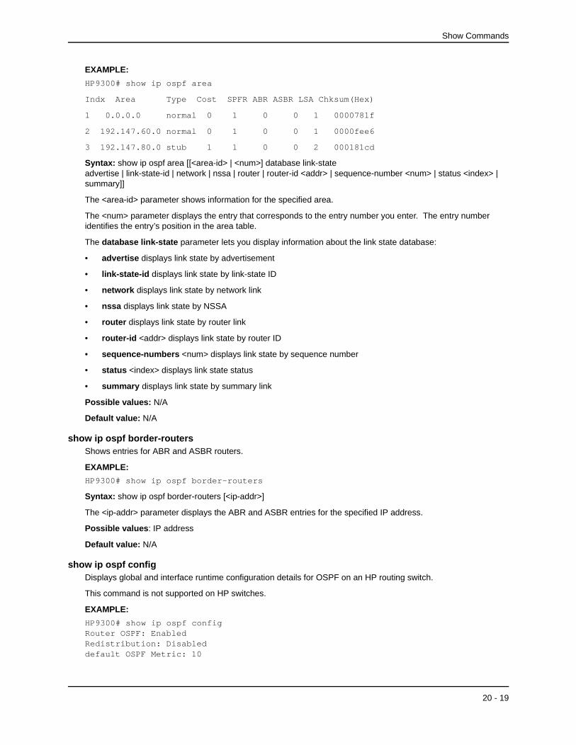
HP9300# show ip ospf area
Indx Area Type Cost SPFR ABR ASBR LSA Chksum(Hex)
1 0.0.0.0 normal 0 1 0 0 1 0000781f
2 192.147.60.0 normal 0 1 0 0 1 0000fee6
3 192.147.80.0 stub 1 1 0 0 2 000181cd
Syntax: show ip ospf area [[<area-id> | <num>] database link-state advertise | link-state-id | network | nssa | router | router-id <addr> | sequence-number <num> | status <index> | summary]]
The <area-id> parameter shows information for the specified area.
The <num> parameter displays the entry that corresponds to the entry number you enter. The entry number identifies the entry’s position in the area table.
The database link-state parameter lets you display information about the link state database:
• advertise displays link state by advertisement
• link-state-id displays link state by link-state ID
• network displays link state by network link
• nssa displays link state by NSSA
• router displays link state by router link
• router-id <addr> displays link state by router ID
• sequence-numbers <num> displays link state by sequence number
• status <index> displays link state status
• summary displays link state by summary link
Possible values: N/A
Default value: N/A
show ip ospf border-routersShows entries for ABR and ASBR routers.
EXAMPLE:
HP9300# show ip ospf border-routers
Syntax: show ip ospf border-routers [<ip-addr>]
The <ip-addr> parameter displays the ABR and ASBR entries for the specified IP address.
Possible values: IP address
Default value: N/A
show ip ospf configDisplays global and interface runtime configuration details for OSPF on an HP routing switch.
This command is not supported on HP switches.
EXAMPLE:
HP9300# show ip ospf configRouter OSPF: EnabledRedistribution: Disableddefault OSPF Metric: 10
20 - 19

Command Line Interface Reference
OSPF Area currently defined:Area-ID Area-Type Cost0.0.0.0 normal 0OSPF Interfaces currently defined:Ethernet Interface: 1ip ospf cost 1ip ospf dead-interval 40ip ospf hello-interval 10ip ospf priority 1ip ospf retransmit-interval 5ip ospf transmit-delay 1ip ospf area 0.0.0.0Ethernet Interface: 2ip ospf cost 1ip ospf dead-interval 40ip ospf hello-interval 10ip ospf priority 1ip ospf retransmit-interval 5ip ospf transmit-delay 1ip ospf area 0.0.0.0
Syntax: show ip ospf config
Possible values: N/A
Default value: N/A
show ip ospf database external-link-stateDisplays information about external link state advertisements stored in the database.
This command is not supported on HP switches.
EXAMPLE:
HP9300> show ip ospf database external-link-state
Index Aging LS ID Router Seq(hex) Chksum1 1332 130.132.81.208 130.130.130.241 80000002 000085ae2 1325 130.132.116.192 130.130.130.241 80000002 0000a37d3 1330 130.132.88.112 130.130.130.241 80000002 0000fb914 1333 130.132.75.48 130.130.130.241 80000002 00000ecc5 1338 130.132.46.224 130.130.130.241 80000002 000067df
Syntax: show ip ospf database external-link-state [advertise <num>] | [link-state-id <ip-addr>] | [router-id <ip-addr>] | [sequence-number <num(Hex)>] | [status <num>]
The advertise <num> parameter displays the hexadecimal data in the specified LSA packet. The <num> parameter identifies the LSA packet by its position in the router’s External LSA table. To determine an LSA packet’s position in the table, enter the show ip ospf database external-link-state command to display the table. See the “Configuring OSPF” chapter of the Advanced Configuration and Management Guide for an example.
The link-state-id <ip-addr> parameter displays the External LSAs for the LSA source specified by <ip-addr>.
The router-id <ip-addr> parameter shows the External LSAs for the specified OSPF router.
The sequence-number <num(Hex)> parameter displays the External LSA entries for the specified hexadecimal LSA sequence number.
Possible values: see above
Default value: N/A
20 - 20

Show Commands
show ip ospf generalDisplays global status information about OSPF for an HP routing switch, specifically:
• count of external Link State Advertisements (LSA)
• sum of external LSA checksums
• number of new LSAs originated by the routing switch
• number of new LSAs received by the routing switch
NOTE: This command is not supported on HP switches.
EXAMPLE:
HP9300# show ip ospf gen
External LSA Counter 0
External LSA Checksum Sum 0000
Originate New LSA Counter 4
Rx New LSA Counter 4
Syntax: show ip ospf general
Possible values: N/A
Default value: N/A
show ip ospf interfaceDisplays information about all or a specific OSPF interface.
This command is not supported on HP switches.
The following information is provided:
• OSPF interface parameters
• State of the interface
• IP address of the designated router
• IP address of the backup designated router
EXAMPLE:
HP9300# show ip ospf interface
Indx Port IP Address Area ID OSPF Mode Priority
1 1 2.0.0.1 0.0.0.0 enabled 1
Transit(sec) Retrans(sec) Hello(sec) Dead(sec) cost
1 5 10 40 1
Type D. Router Backup D. Router events state
broadcast 2.0.0.1 2.0.0.2 1 DRouter
Authentication-Key: None
Syntax: show ip ospf interface [<ip-addr>]
The <ip-addr> parameter displays the OSPF interface information for the specified IP address.
Possible values: N/A
Default value: N/A
20 - 21

Command Line Interface Reference
show ip ospf database link-stateDisplays the router, network, summary and summary ASBR link state advertisements. The status parameter provides a detailed display. The advertise parameter provides a summary.
This command is not supported on HP switches.
EXAMPLE:
HP9300# show ip ospf database link-state status
Index: 1 Area ID: 0.0.0.0
Age(sec) Type LS ID Router Seq(hex) Chksum(hex)
565 Summary 192.147.200.0 192.147.80.3 80000001 781f
Syntax: show ip ospf database link-state [advertise <num>] | [link-state-id <ip-addr>] | [network] | [router] | [router-id <num>] | [sequence-number <num(Hex)>] | [status <num>] [summary]
The advertise <num> parameter displays the hexadecimal data in the specified LSA packet. The <num> parameter identifies the LSA packet by its position in the routing switch’s LSA table. To determine an LSA packet’s position in the table, enter the show ip ospf database link-state command to display the table. See the “Configuring OSPF” chapter of the Advanced Configuration and Management Guide for an example.
for an example.
The link-state-id <ip-addr> parameter displays the External LSAs for the LSA source specified by <ip-addr>.
The router-id <ip-addr> parameter shows the External LSAs for the specified OSPF router.
The sequence-number <num(Hex)> parameter displays the External LSA entries for the specified hexadecimal LSA sequence number.
Possible values: N/A
Default value: N/A
show ip ospf neighborDisplays information about all neighbor routers or a specific neighbor router.
This command is not supported on HP switches.
The following information is shown for an HP routing switch:
• neighbor router ID
• neighbor IP address
• neighbor state
• number of times the neighbor state has changed
• count of packets retransmitted to the neighbor router
EXAMPLE:
HP9300> show ip ospf neighbor
Port Address Pri State Neigh Address Neigh ID Ev Opt Cnt8 212.76.7.251 1 full 212.76.7.200 173.35.1.220 23 2 0
Syntax: show ip ospf neighbor [router-id <ip-addr>] | [<num>]
The router-id <ip-addr> parameter displays only the neighbor entries for the specified router.
The <num> parameter displays the table beginning at the specified entry number.
Possible values: see above
Default value: N/A
20 - 22

Show Commands
show ip ospf routesDisplays the OSPF route table. See the “Configuring OSPF” chapter of the Advanced Configuration and Management Guide for information about the fields in this display.
This command is not supported on HP switches.
EXAMPLE:
To display OSPF route information, enter the following command at any CLI level:
HP9300> show ip ospf routes
Index Destination Mask Path_Cost Type2_Cost Path_Type1 212.95.7.0 255.255.255.0 1 0 Intra Adv_Router Link_State Dest_Type State Tag Flags 173.35.1.220 212.95.7.251 Network Valid 00000000 7000 Paths Out_Port Next_Hop Type Arp_Index State 1 5/6 209.95.7.250 OSPF 8 84 00
Index Destination Mask Path_Cost Type2_Cost Path_Type2 11.3.63.0 255.255.255.0 11 0 Inter Adv_Router Link_State Dest_Type State Tag Flags 209.95.7.250 11.3.63.0 Network Valid 00000000 0000 Paths Out_Port Next_Hop Type Arp_Index State 1 5/6 209.95.7.250 OSPF 8 84 00
Syntax: show ip ospf routes [<ip-addr>]
The <ip-addr> parameter specifies a destination IP address. If you use this parameter, only the route entries for that destination are shown.
Possible values: see above
Default value: N/A
show ip ospf trapDisplays the list of all OSPF traps and their current state of enabled or disabled.
This command is not supported on HP switches.
EXAMPLE:
HP9300(config)# show ip ospf trap
Interface State Change Trap: Enabled
Virtual Interface State Change Trap: Enabled
Neighbor State Change Trap: Enabled
Virtual Neighbor State Change Trap Enabled
Interface Configuration Error Trap: Enabled
Virtual Interface Configuration Error Trap: Enabled
Interface Authentication Failure Trap: Enabled
Virtual Interface Authentication Failure Trap: Enabled
Interface Receive Bad Packet Trap: Enabled
Virtual Interface Receive Bad Packet Trap: Enabled
Interface Retransmit Packet Trap: Enabled
Virtual Interface Retransmit Packet Trap: Enabled
Originate LSA Trap: Enabled
20 - 23

Command Line Interface Reference
Originate MaxAge LSA Trap: Enabled
Originate MaxAge LSA Trap: Enabled
Link State Database Overflow Trap Enabled
Link State Database Approaching Overflow Trap Enabled
Syntax: show ip ospf trap
Possible values: N/A
Default value: N/A
show ip ospf virtual-linkDisplays transit area, router ID and transit specifics for an OSPF virtual link on an HP routing switch.
This command is not supported on HP switches.
EXAMPLE:
HP9300# show ip ospf virtual-link 1
Indx Transit Area Router ID Transit(sec) Retrans(sec) Hello(sec)
1 192.147.60.0 192.147.180.30 1 5 10
Dead(sec) events state Authentication-Key
40 0 down None
Syntax: show ip ospf virtual-link [<num>]
The <num> parameter displays the table beginning at the specified entry number.
Possible values: see above
Default value: N/A
show ip ospf virtual-neighborDisplays the OSPF virtual neighbor information.
This command is not supported on HP switches.
EXAMPLE:
HP9300# show ip ospf virtual-neighbor 3
Syntax: show ip ospf virtual-neighbor [<num>]
The <num> parameter displays the table beginning at the specified entry number.
Possible values: see above
Default value: N/A
show ip pim bsrShows Bootstrap router (BSR) information for PIM Sparse.
EXAMPLE:
To display BSR information, enter the following command at any CLI level:
HP9300(config-pim-router)# show ip pim bsr
PIMv2 Bootstrap information
This system is the elected Bootstrap Router (BSR) BSR address: 207.95.7.1 Uptime: 00:33:52, BSR priority: 5, Hash mask length: 32 Next bootstrap message in 00:00:20
20 - 24

Show Commands
Next Candidate-RP-advertisement in 00:00:10 RP: 207.95.7.1 group prefixes: 224.0.0.0 / 4Candidate-RP-advertisement period: 60
This example show information displayed on a routing switch that has been elected as the BSR. The following example shows information displayed on a routing switch that is not the BSR. Notice that some fields shown in the example above do not appear in the example below.
HP9300(config-pim-router)# show ip pim bsr
PIMv2 Bootstrap information local BSR address = 207.95.7.1 local BSR priority = 5
See the “Configuring IP Multicast Protocols” chapter of the Advanced Configuration and Management Guide for an explanation of the information shown by this command.
Syntax: show ip pim bsr
Possible values: see above
Default value: N/A
show ip pim flowcacheDisplays all active PIM flows for an HP routing switch. A flow is a cached forwarding entry.
This command is not supported on HP switches.
EXAMPLE:
HP9300(config-pim-router)# show ip pim flowcache
Source Group Parent CamFlags CamIndex Fid Flags1 209.157.24.162 239.255.162.1 v2 00000700 2023 00004411 F2 209.157.24.162 239.255.162.1 v2 00000700 201b 00004411 F3 209.157.24.162 239.255.162.1 v2 00000700 201d 00004411 F4 209.157.24.162 239.255.162.1 v2 00000700 201e 00004411 F
See the “Configuring IP Multicast Protocols” chapter of the Advanced Configuration and Management Guide for an explanation of the information shown by this command.
Syntax: show ip pim flowcache
Possible values: N/A
Default value: N/A
show ip pim groupDisplays all active PIM groups by interface—both physical and virtual—for an HP routing switch. Physical ports are displayed as numerals only. Virtual interfaces are preceded with a ‘v’ as in the example below.
This command is not supported on HP switches.
EXAMPLE:
HP9300(config)# show ip pim group
Index Group Port
1 224.2.230.64 v01
2 239.255.0.1 v01
See the “Configuring IP Multicast Protocols” chapter of the Advanced Configuration and Management Guide for an explanation of the information shown by this command.
Syntax: show ip pim group
20 - 25

Command Line Interface Reference
Possible values: N/A
Default value: N/A
show ip pim interfaceLists all active interfaces configured for an HP routing switch.
This command is not supported on HP switches.
EXAMPLE:
HP9300(config)# sh ip pim interface
Interface Ethernet 1
TTL Threshold: 1, Enabled
Local Address: 207.95.18.20
Interface Ethernet 3
TTL Threshold: 1, Enabled
Local Address: 207.95.5.1
Syntax: show ip pim interface [ethernet <portnum> | ve <num>]
The ethernet <portnum> parameter lets you specify a routing switch port.
The ve <num> parameter lets you specify a virtual interface (VE).
Possible values: N/A
Default value: N/A
show ip pim mcacheDisplays all forwarding entries for an HP routing switch with PIM enabled.
This command is not supported on HP switches.
In the example below, the source, group pair is defined for ports 2 and 3 as listed in hex in the PortMask column.
EXAMPLE:
HP9300(config-pim-router)# show ip pim mcache
1 (*,239.255.162.1) RP207.95.7.1 forward port v1, Count 2 member ports ethe 3/3 virtual ports v2 prune ports virtual prune ports
2 (209.157.24.162,239.255.162.4) forward port v2, flags 00004900 Count 130 member ports virtual ports prune ports virtual prune ports
3 (209.157.24.162,239.255.162.1) forward port v2, flags 00005a01 Count 12 member ports ethe 3/8 virtual ports prune ports virtual prune ports
Syntax: show ip pim mcache [<source> <group>]
Possible values: N/A
Default value: N/A
20 - 26

Show Commands
show ip pim nbrDisplays all PIM neighbor routers for physical, virtual and tunnel interfaces.
Port numbers preceded by a ‘T’ are tunnel interfaces, ‘E’ refers to physical interfaces and ‘VE’ refers to routed interfaces within a VLAN.
This command is not supported on HP switches.
EXAMPLE:
HP9300(config-pim-router)# show ip pim nbr
Port Neighbor Holdtime Age UpTime sec sec sece3/8 207.95.8.10 180 60 900Port Neighbor Holdtime Age UpTime sec sec secv1 207.95.6.2 180 60 900
Syntax: show ip pim nbr
See the “Configuring IP Multicast Protocols” chapter of the Advanced Configuration and Management Guide for an explanation of the information shown by this command.
Possible values: N/A
Default value: N/A
show ip pim pruneShows those prune states that are active on an HP routing switch with PIM enabled.
Port numbers preceded by a ‘T’ are tunnel interfaces, ‘E’ refers to physical interfaces and ‘VE’ refers to routed interfaces within a VLAN.
This command is not supported on an HP switch.
EXAMPLE:
HP9300(config)# show ip pim nbr
Port SourceNet Group Nbr Age
T16 207.95.5.0 239.255.0.2 207.95.6.10 0
Syntax: show ip pim prune
Possible values: N/A
Default value: N/A
show ip pim rp-candidateDisplays candidate Rendezvous Point (RP) information for PIM Sparse.
EXAMPLE:
To display candidate RP information, enter the following command at any CLI level:
HP9300(config-pim-router)# show ip pim rp-candidate
Next Candidate-RP-advertisement in 00:00:10 RP: 207.95.7.1 group prefixes: 224.0.0.0 / 4
Candidate-RP-advertisement period: 60
This example show information displayed on a routing switch that is a candidate RP. The following example shows the message displayed on a routing switch that is not a candidate RP.
HP9300(config-pim-router)# show ip pim bsr
20 - 27

Command Line Interface Reference
This system is not a Candidate-RP.
See the “Configuring IP Multicast Protocols” chapter of the Advanced Configuration and Management Guide for an explanation of the information shown by this command.
Syntax: show ip pim rp-candidate
Possible values: N/A
Default value: N/A
show ip pim rp-hashShows RP information for a specific PIM Sparse group.
EXAMPLE:
To display RP information for a PIM Sparse group, enter the following command at any CLI level:
HP9300(config-pim-router)# show ip pim rp-hash 239.255.162.1
RP: 207.95.7.1, v2 Info source: 207.95.7.1, via bootstrap
See the “Configuring IP Multicast Protocols” chapter of the Advanced Configuration and Management Guide for an explanation of the information shown by this command.
Syntax: show ip pim rp-hash <group-addr>
The <group-addr> parameter is the address of a PIM Sparse IP multicast group.
Possible values: N/A
Default value: N/A
show ip pim rp-mapShows PIM Sparse RP-to-group mappings.
EXAMPLE:
To display RP-to-group-mappings, enter the following command at any CLI level:
HP9300(config-pim-router)# show ip pim rp-map
Group address RP address-------------------------------239.255.162.1 207.95.7.1
See the “Configuring IP Multicast Protocols” chapter of the Advanced Configuration and Management Guide for an explanation of the information shown by this command.
Syntax: show ip pim rp-map
Possible values: N/A
Default value: N/A
show ip pim rp-setShows the RP set list on a routing switch configured as a PIM Sparse router.
EXAMPLE:
To display the RP set list, enter the following command at any CLI level:
HP9300(config-pim-router)# show ip pim rp-set
Number of group prefixes = 1
Group prefix = 224.0.0.0/4 # RPs expected/received: 1 RP 1: 207.95.7.1 priority=0 age=0
20 - 28

Show Commands
See the “Configuring IP Multicast Protocols” chapter of the Advanced Configuration and Management Guide for an explanation of the information shown by this command.
Syntax: show ip pim rp-set
Possible values: N/A
Default value: N/A
show ip pim sparseShows global PIM Sparse parameters.
EXAMPLE:
To display PIM Sparse configuration information, enter the following command at any CLI level:
HP9300(config-pim-router)# show ip pim sparse
Global PIM Sparse Mode Settings Hello interval: 60, Neighbor timeout: 180 Bootstrap Msg interval: 130, Candidate-RP Advertisement interval: 60 Join/Prune interval: 60, SPT Threshold: 1
Interface Ethernet e3/8TTL Threshold: 1, EnabledLocal Address: 207.95.8.1
Interface Ve 1TTL Threshold: 1, EnabledLocal Address: 207.95.6.1
See the “Configuring IP Multicast Protocols” chapter of the Advanced Configuration and Management Guide for an explanation of the information shown by this command.
Syntax: show ip pim sparse
Possible values: N/A
Default value: N/A
show ip pim trafficDisplays active PIM interfaces and their statistics for an HP routing switch.
Port numbers preceded by a ‘T’ are tunnel interfaces, ‘E’ refers to physical interfaces and ‘VE’ refers to routed interfaces within a VLAN.
This command is not supported on HP switches.
EXAMPLE:
HP9300(config)# show ip pim traffic
Port Hello Join Prune Graft Assert
[Rx Tx] [Rx Tx] [Rx Tx] [Rx Tx] [Rx Tx]
e5 0 2 0 0 0 0 0 0 0 0
t1 538 540 0 0 3 775 0 4 0 0
ve1 0 541 0 0 0 0 0 0 0 0
ve3 0 541 0 0 0 0 0 0 0 0
Total 538 2163 0 0 33 775 0 4 0 0
20 - 29

Command Line Interface Reference
Port Hello J/P Register RegStop Assert [Rx Tx] [Rx Tx] [Rx Tx] [Rx Tx] [Rx Tx]e3/8 19 19 32 0 0 0 37 0 0 0
Port Hello J/P Register RegStop Assert [Rx Tx] [Rx Tx] [Rx Tx] [Rx Tx] [Rx Tx]v1 18 19 0 20 0 0 0 0 0 0
Port Hello J/P Register RegStop Assert [Rx Tx] [Rx Tx] [Rx Tx] [Rx Tx] [Rx Tx]v2 0 19 0 0 0 16 0 0 0 0
Total 37 57 32 0 0 0 0 0 0 0IGMP Statistics: Total Recv/Xmit 85/110 Total Discard/chksum 0/0
This example shows output for regular PIM (dense mode) and PIM Sparse. The regular PIM statistics are listed first, followed by the PIM Sparse statistics. Rows are displayed only for the type of PIM configured on the routing switch. See the “Configuring IP Multicast Protocols” chapter of the Advanced Configuration and Management Guide for an explanation of the information shown by this command.
Syntax: show ip pim traffic
Possible values: N/A
Default value: N/A
show ip policyDisplays the configured global and local session policies defined using the ip policy command.
This command does not apply to routing switches.
EXAMPLE:
Index Priority Protocol Socket Type
1 7 tcp pop3 global
2 7 udp dns global
Syntax: show ip policy
Possible values: N/A
Default value: N/A
show ip prefix-listsDisplays the configured IP prefix lists.
show ip ripDisplays the IP/RIP filters defined for an HP routing switch and its neighbor router.
This command is not supported on HP switches.
EXAMPLE:
HP9300(config)# show ip rip
RIP Route Filter Table
Index Action Route IP Address Sub-net Mask
1 Permit 192.58.5.3 255.255.255.0
RIP Neighbor Filter Table
Index Action Neighbor IP address
1 Permit 195.98.7.2
20 - 30

Show Commands
Syntax: show ip rip
Possible values: N/A
Default value: N/A
show ip routeDisplays active IP routes on an HP routing switch. See the “Configuring IP and IP/RIP” chapter of the Advanced Configuration and Management Guide for information about the fields in this display.
This command is not supported on HP switches.
EXAMPLE:
HP9300> show ip route
Total number of IP routes: 514Starting index: 1 B:BGP D:Directly-Connected R:RIP S:Static O:OSPFIA:OSPF inter area E1:OSPF external type 1 E2:OSPF external type 2
Destination NetMask Gateway Port Cost Type
1.1.0.0 255.255.0.0 99.1.1.2 1/1 2 R1.2.0.0 255.255.0.0 99.1.1.2 1/1 2 R1.3.0.0 255.255.0.0 99.1.1.2 1/1 2 R1.4.0.0 255.255.0.0 99.1.1.2 1/1 2 R
Syntax: show ip route [<ip-addr> | <num> | bgp | direct | ospf | rip | static]
The <ip-addr> parameter displays the route to the specified IP address.
The <num> option display the route table entry whose row number corresponds to the number you specify. For example, if you want to display the tenth row in the table, enter “10”.
NOTE: To simplify the table, the row number is not displayed in software release 05.2.00 and later.
The bgp option displays the BGP4 routes.
The direct option displays the directly attached routes.
The ospf option displays the OSPF routes.
The rip option displays the RIP routes.
The static option displays the static IP routes.
Possible values: see above
Default value: N/A
show ip srpDisplays the current settings of SRP on an HP routing switch.
This command is not supported on HP switches.
EXAMPLE:
HP9300# show ip srp
SRP Interfaces currently defined:
Ethernet Interface: 1
ip srp ip address 192.147.200.165
ip srp virtual router ip address 192.147.200.100
ip srp other router ip address 192.147.200.170
20 - 31

Command Line Interface Reference
ip srp state Active
ip srp preference level 50
ip srp track port 3
ip srp keep alive time 15
ip srp router dead interval 30
Syntax: show ip srp
Possible values: N/A
Default value: N/A
show ip trafficDisplays IP (including ICMP, UDP, TCP, and RIP) traffic statistics for an HP switch or routing switch.
EXAMPLE:
HP9300# show ip traffic
IP Statistics
464 received, 2267 sent, 0 forwarded
0 filtered, 0 fragmented, 0 reassembled, 0 bad header
0 no route, 0 unknown proto, 0 no buffer, 0 other errors
ICMP Statistics
Received:
0 total, 0 errors, 0 unreachable, 0 time exceed
0 parameter, 0 source sequence, 0 redirect, 0 echo,
0 echo reply, 0 timestamp, 0 timestamp rely, 0 addr mask
0 addr mask reply, 0 irdp advertisement, 0 irdp solicitation
Sent:
54 total, 0 errors, 0 unreachable, 0 time exceed
0 parameter, 0 source sequence, 0 redirect, 0 echo,
0 echo reply, 0 timestamp, 0 timestamp rely, 0 addr mask
0 addr mask reply, 54 irdp advertisement, 0 irdp solicitation
NOTE: This example is an excerpt, not a complete display.
Syntax: show ip traffic
Possible values: N/A
Default value: N/A
show ip vrrpDisplays VRRP statistics.
HP9300# show ip vrrp statInterface ethernet e 1/6 rxed vrrp header error count = 0 rxed vrrp auth error count = 0 rxed vrrp auth passwd mismatch error count = 0 rxed vrrp vrid not found error count = 0
20 - 32

Show Commands
VRID 1 rxed arp packet drop count = 0 rxed ip packet drop count = 0 rxed vrrp port mismatch count = 0 rxed vrrp ip address mismatch count = 0 rxed vrrp hello interval mismatch count = 0 rxed vrrp priority zero from master count = 0 rxed vrrp higher priority count = 0 transitioned to master state count = 1 transitioned to backup state count = 0
Syntax: show ip vrrp [stat]
Possible values: N/A
Default value: N/A
show ipxDisplays IPX global parameters for an HP routing switch.
This command is not supported on HP switches.
EXAMPLE:
HP9300# show ipx
Global Settings
IPX Routing Mode: Enabled
IPX NetBIOS (type 20): Disallowed
Syntax: show ipx
Possible values: N/A
Default value: N/A
show ipx cacheDisplays summary by port, network number, forwarding (Next Hop Router), MAC address, out filter status and frame type for an HP switch or routing switch.
EXAMPLE:
HP9300# show ipx cache
Total number of IPX cache entries 3
Forwarding
Index Network Router Out-Filter Frame-Type Port
1 11110007 0000.0000.0000 off ethernet_802.3 7
2 11110005 0000.0000.0000 off ethernet_802.3 5
3 32D564FA 00a0.24bf.89ca off ethernet_802.3 5
Syntax: show ipx cache [<num(hex)>]
Possible values: The optional <num(hex)> parameter lets you specify an IPX network number.
Default value: N/A
show ipx interface Lists network number, MAC address, and port state and frame type for all interfaces or a specific IPX interface on an HP routing switch.
To display data on all interfaces, enter the command show ipx interface.
20 - 33

Command Line Interface Reference
This command is not supported on HP switches.
EXAMPLE:
To display data for interface 5, enter the following:
HP9300# show ipx interface ethernet 3/5
Interface Ethernet 3/5 MAC address: 00e0.5284.0b44 Port state: UP IPX network: 0000ABCD Frame type: ethernet_snap Allow NetBIOS: NO rip-interval: 60 rip-max-packet-size: 432 rip-multiplier: 3 sap-interval: 60 sap-max-packet-size: 480 sap-multiplier: 3
Syntax: show ipx interface [ethernet <portnum> | ve <num>]
The ethernet <portnum> parameter lets you specify a router port.
The ve <num> parameter lets you specify a virtual interface (VE).
Possible values: see above
Default value: N/A
show ipx routeDisplays active IPX routes noting hop, tick and port for an HP routing switch.
EXAMPLE:
HP9300# show ipx route
Total number of IPX route entries 3
Forwarding
Index Network Router Hops Ticks Port
1 11110007 0000.0000.0000 0 1 7
2 32D564FA 00a0.24bf.89ca 1 2 5
3 11110005 0000.0000.0000 0 1 5
Syntax: show ipx route [<num(hex)>]
Possible values: The optional <num(hex)> parameter lets you specify an IPX network number.
Default value: N/A
show ipx serversDisplays IPX servers defined for an HP routing switch.
This command is not supported on HP switches.
EXAMPLE:
HP9300# show ipx servers
Total number of IPX server entries 3
Index Network Node Socket Type Hops
1 32D564FA 0000.0000.0001 0005 026B 1
Server-name: HPD
2 32D564FA 0000.0000.0001 4006 0278 1
Server-name: HPM
3 32D564FA 0000.0000.0001 0451 0004 1
Server-name: HP-MPR2
20 - 34

Show Commands
Syntax: show ipx servers [<name>]
Possible values: The optional <name> parameter lets you specify a server name.
Default value: N/A
show ipx trafficDisplays a port summary of total IPX packets forwarded. It also breaks down the packets by transmit and receive. Totals for dropped and filtered packets are also shown.
This command is supported on both HP switches and routing switches.
EXAMPLE:
HP9300# show ipx traffic
Dropped Filtered
Port Forward Receive Transmit Receive Transmit Receive Transmit
5 46 36 8 2 0 0 0
7 0 0 6 0 0 0 0
Tot 46 36 14 2 0 0 0
Syntax: show ipx traffic
Possible values: N/A
Default value: N/A
show loggingDisplays the SNMP event log.
Syntax: show logging
Static and Dynamic Buffers
The software provides two separate buffers:
• Static – logs power supply failures, fan failures, and temperature warning or shutdown messages
• Dynamic – logs all other message types
In the static log, new messages replace older ones, so only the most recent message is displayed. For example, only the most recent temperature warning message will be present in the log. If multiple temperature warning messages are sent to the log, the latest one replaces the previous one. The static buffer is not configurable.
The message types that appear in the static buffer do not appear in the dynamic buffer. The dynamic buffer contains up to the maximum number of messages configured for the buffer (50 by default), then begins removing the oldest messages (at the bottom of the log) to make room for new ones.
The static and dynamic buffers are both displayed when you display the log.
HP9300(config)# show logging
Syslog logging: enabled (0 messages dropped, 0 flushes, 0 overruns) Buffer logging: level ACDMEINW, 3 messages logged level code: A=alert C=critical D=debugging M=emergency E=error
I=informational N=notification W=warning
Static Log Buffer:Dec 15 19:04:14:A:Fan 1, fan on right connector, failed
Dynamic Log Buffer (50 entries):Dec 15 18:46:17:I:Interface ethernet4, state up
20 - 35

Command Line Interface Reference
Dec 15 18:45:21:I:Bridge topology change, vlan 4095, interface 4, changedstate to forwardingDec 15 18:45:15:I:Warm start
Notice that the static buffer contains two separate messages for fan failures. Each message of each type has its own buffer. Thus, if you replace fan 1 but for some reason that fan also fails, the software replaces the first message about the failure of fan 1 with the newer message. The software does not overwrite the message for fan 2, unless the software sends a newer message for fan 2.
When you clear log entries, you can selectively clear the static or dynamic buffer, or you can clear both. For example, to clear only the dynamic buffer, enter the following command at the Privileged EXEC level:
HP9300# clear logging dynamic-buffer
Syntax: clear logging [dynamic-buffer | static-buffer]
You can specify dynamic-buffer to clear the dynamic buffer or static-buffer to clear the static buffer. If you do not specify a buffer, both buffers are cleared.
Time Stamps
The contents of the time stamp differ depending on whether you have set the time and date on the onboard system clock.
• If you have set the time and date on the onboard system clock, the date and time are shown in the following format:
mm dd hh:mm:ss
where:
• mm – abbreviation for the name of the month
• dd – day
• hh – hours
• mm – minutes
• ss – seconds
For example, “Oct 15 17:38:03” means October 15 at 5:38 PM and 3 seconds.
• If you have not set the time and date on the onboard system clock, the time stamp shows the amount of time that has passed since the device was booted, in the following format:
<num>d<num>h<num>m<num>s
where:
• <num>d – day
• <num>h – hours
• <num>m – minutes
• <num>s – seconds
For example, “188d1h01m00s” means the device had been running for 188 days, 11 hours, one minute, and zero seconds when the Syslog entry with this time stamp was generated.
Example of Syslog Messages on a Device Whose Onboard Clock Is Set
The example shows the format of messages on a device whose onboard system clock has been set. Each time stamp shows the month, the day, and the time of the system clock when the message was generated. For example, the system time when the most recent message (the one at the top) was generated was October 15 at 5:38 PM and 3 seconds.
20 - 36

Show Commands
HP9300(config)# show log
Syslog logging: enabled (0 messages dropped, 0 flushes, 0 overruns) Buffer logging: level ACDMEINW, 38 messages logged level code: A=alert C=critical D=debugging M=emergency E=error I=informational N=notification W=warning
Static Log Buffer:Dec 15 19:04:14:A:Fan 1, fan on right connector, failedDec 15 19:00:14:A:Fan 2, fan on left connector, failed
Dynamic Log Buffer (50 entries):Oct 15 17:38:03:warning:list 101 denied tcp 209.157.22.191(0)(Ethernet 4/18 0010.5a1f.77ed) -> 198.99.4.69(http), 2 packets
Oct 15 07:03:30:warning:list 101 denied tcp 209.157.22.26(0)(Ethernet 4/18 0010.5a1f.77ed) -> 198.99.4.69(http), 2 packets
Oct 15 06:58:30:warning:list 101 denied tcp 209.157.22.198(0)(Ethernet 4/18 0010.5a1f.77ed) -> 198.99.4.69(http), 1 packets
Example of Syslog Messages on a Device Whose Onboard Clock Is Not Set
The example shows the format of messages on a device whose onboard system clock is not set. Each time stamp shows the amount of time the device had been running when the message was generated. For example, the most recent message, at the top of the list of messages, was generated when the device had been running for 21 days, seven hours, two minutes, and 40 seconds.
HP9300(config)# show log
Syslog logging: enabled (0 messages dropped, 0 flushes, 0 overruns) Buffer logging: level ACDMEINW, 38 messages logged level code: A=alert C=critical D=debugging M=emergency E=error I=informational N=notification W=warning
Static Log Buffer:
Dynamic Log Buffer (50 entries):21d07h02m40s:warning:list 101 denied tcp 209.157.22.191(0)(Ethernet 4/18 0010.5a1f.77ed) -> 198.99.4.69(http), 2 packets
19d07h03m30s:warning:list 101 denied tcp 209.157.22.26(0)(Ethernet 4/18 0010.5a1f.77ed) -> 198.99.4.69(http), 2 packets
17d06h58m30s:warning:list 101 denied tcp 209.157.22.198(0)(Ethernet 4/18 0010.5a1f.77ed) -> 198.99.4.69(http), 1 packets
List of Messages
The following table lists all of the Syslog messages. Note that some of the messages apply only to routing switches. The messages are listed by message level, in the following order:
• Emergencies (none)
• Alerts
• Critical (none)
• Errors (none)
• Warnings
• Notifications
• Informational
• Debugging
20 - 37

Command Line Interface Reference
Table 20.1: HP Syslog Messages
Message Level Message Explanation
Alert Power supply <num>, <location>, failed A power supply has failed.
The <num> is the power supply number.
The <location> describes where the failed power supply is in the chassis. The location can be one of the following:
• In 4-slot Chassis devices:
• left side power supply
• right side power supply
• In 8-slot Chassis devices:
• bottom power supply
• middle bottom power supply
• middle top power supply
• top power supply
• In Fixed-port devices:
• power supply on right connector
• power supply on left connector
Alert Fan <num>, <location>, failed A fan has failed.
The <num> is the power supply number.
The <location> describes where the failed power supply is in the chassis. The location can be one of the following:
• In 4-slot Chassis devices:
• left side panel, back fan
• left side panel, front fan
• rear/back panel, left fan
• rear/back panel, right fan
• In 8-slot Chassis devices:
• rear/back panel, top fan
• rear/back panel, bottom fan
• top panel, fan
• top panel, fan
• In Fixed-port devices:
• fan on right connector
• fan on left connector
20 - 38
Show Commands
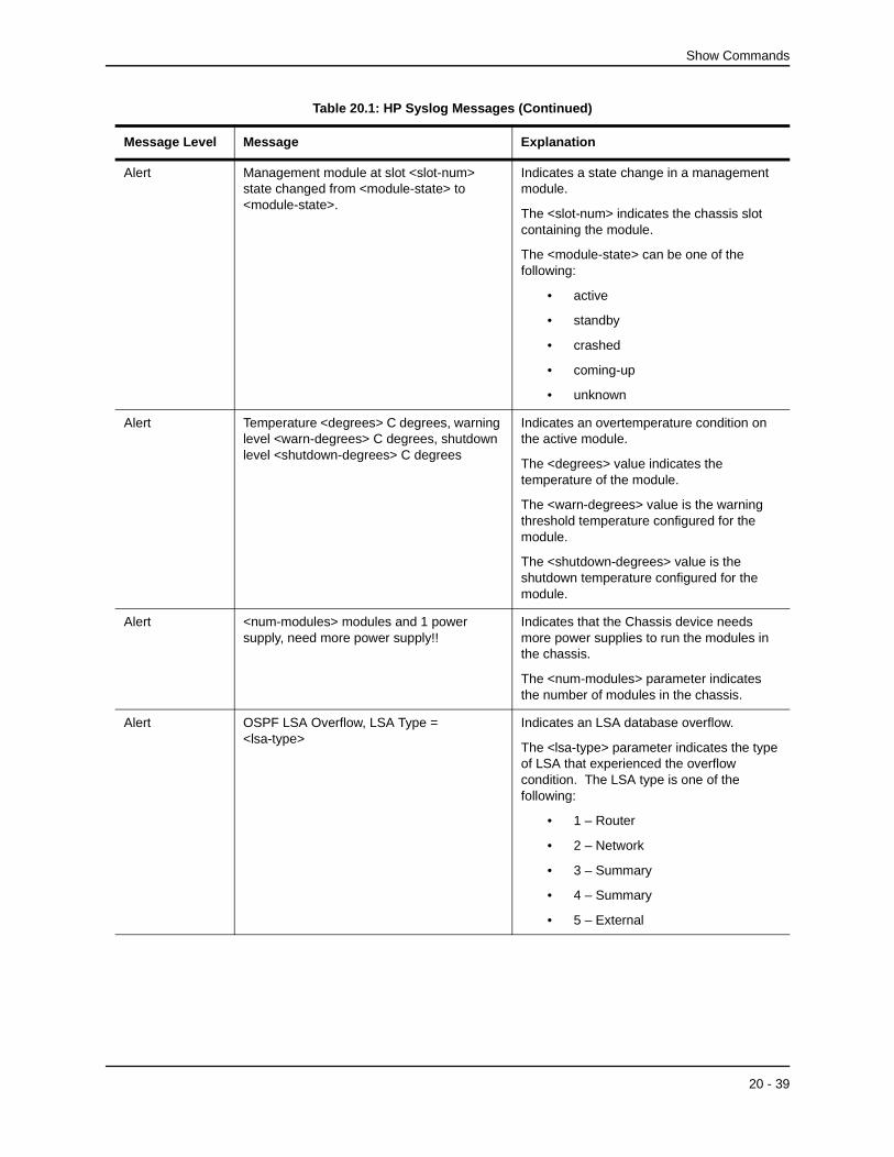
Alert Management module at slot <slot-num> state changed from <module-state> to <module-state>.
Indicates a state change in a management module.
The <slot-num> indicates the chassis slot containing the module.
The <module-state> can be one of the following:
• active
• standby
• crashed
• coming-up
• unknown
Alert Temperature <degrees> C degrees, warning level <warn-degrees> C degrees, shutdown level <shutdown-degrees> C degrees
Indicates an overtemperature condition on the active module.
The <degrees> value indicates the temperature of the module.
The <warn-degrees> value is the warning threshold temperature configured for the module.
The <shutdown-degrees> value is the shutdown temperature configured for the module.
Alert <num-modules> modules and 1 power supply, need more power supply!!
Indicates that the Chassis device needs more power supplies to run the modules in the chassis.
The <num-modules> parameter indicates the number of modules in the chassis.
Alert OSPF LSA Overflow, LSA Type = <lsa-type>
Indicates an LSA database overflow.
The <lsa-type> parameter indicates the type of LSA that experienced the overflow condition. The LSA type is one of the following:
• 1 – Router
• 2 – Network
• 3 – Summary
• 4 – Summary
• 5 – External
Table 20.1: HP Syslog Messages (Continued)
Message Level Message Explanation
20 - 39

Command Line Interface Reference
Warning Locked address violation at interface e<portnum>, address <mac-address>
Indicates that a port on which you have configured a lock-address filter received a packet that was dropped because the packet’s source MAC address did not match an address learned by the port before the lock took effect.
The e<portnum> is the port number.
The <mac-address> is the MAC address that was denied by the address lock.
Assuming that you configured the port to learn only the addresses that have valid access to the port, this message indicates a security violation.
Warning NTP server <ip-addr> failed to respond Indicates that a Simple Network Time Protocol (SNTP) server did not respond to the device’s query for the current time.
The <ip-addr> indicates the IP address of the SNTP server.
Warning Dup IP <ip-addr> detected, sent from MAC <mac-addr> interface <portnum>
Indicates that the HP device received a packet from another device on the network with an IP address that is also configured on the HP device.
The <ip-addr> is the duplicate IP address.
The <mac-addr> is the MAC address of the device with the duplicate IP address.
The <portnum> is the HP port that received the packet with the duplicate IP address. The address is the packet’s source IP address.
Table 20.1: HP Syslog Messages (Continued)
Message Level Message Explanation
20 - 40

Show Commands
Warning list <acl-num> denied <ip-proto> <src-ip-addr> (<src-tcp/udp-port>) (Ethernet <portnum> <mac-addr>) -> <dst-ip-addr>(<dst-tcp/udp-port>), <num> packets
Indicates that an Access Control List (ACL) denied (dropped) packets.
The <acl-num> indicates the ACL number. Numbers 1 – 99 indicate standard ACLs. Numbers 100 – 199 indicate extended ACLs.
The <ip-proto> indicates the IP protocol of the denied packets.
The <src-ip-addr> is the source IP address of the denied packets.
The <src-tcp/udp-port> is the source TCP or UDP port, if applicable, of the denied packets.
The <portnum> indicates the port number on which the packet was denied.
The <mac-addr> indicates the source MAC address of the denied packets.
The <dst-ip-addr> indicates the destination IP address of the denied packets.
The <dst-tcp/udp-port> indicates the destination TCP or UDP port number, if applicable, of the denied packets.
The <num> indicates how many packets matching the values above were dropped during the five-minute interval represented by the log entry.
Warning rip filter list <list-num> <direction> V1 | V2 denied <ip-addr>, <num> packets
Indicates that a RIP route filter denied (dropped) packets.
The <list-num> is the ID of the filter list.
The <direction> indicates whether the filter was applied to incoming packets or outgoing packets. The value can be one of the following:
• in
• out
The V1 or V2 value specifies the RIP version (RIPv1 or RIPv2).
The <ip-addr> indicates the network number in the denied updates.
The <num> indicates how many packets matching the values above were dropped during the five-minute interval represented by the log entry.
Table 20.1: HP Syslog Messages (Continued)
Message Level Message Explanation
20 - 41

Command Line Interface Reference
Warning mac filter group denied packets on port <portnum> src macaddr <mac-addr>, <num> packets
Indicates that a Layer 2 MAC filter group configured on a port has denied packets.
The <portnum> is the port on which the packets were denied.
The <mac-addr> is eth source AMC address of the denied packets.
The <num> indicates how many packets matching the values above were dropped during the five-minute interval represented by the log entry.
Notification Module was inserted to slot <slot-num> Indicates that a module was inserted into a chassis slot.
The <slot-num> is the number of the chassis slot into which the module was inserted.
Notification Module was removed from slot <slot-num> Indicates that a module was removed from a chassis slot.
The <slot-num> is the number of the chassis slot from which the module was removed.
Notification OSPF interface state changed,rid <router-id>, intf addr <ip-addr>, state <ospf-state>
Indicates that the state of an OSPF interface has changed.
The <router-id> is the router ID of the HP device.
The <ip-addr> is the interface’s IP address.
The <ospf-state> indicates the state to which the interface has changed and can be one of the following:
• down
• loopback
• waiting
• point-to-point
• designated router
• backup designated router
• other designated router
• unknown
Table 20.1: HP Syslog Messages (Continued)
Message Level Message Explanation
20 - 42

Show Commands
Notification OSPF virtual intf state changed, rid <router-id>, area <area-id>, nbr <ip-addr>, state <ospf-state>
Indicates that the state of an OSPF virtual interface has changed.
The <router-id> is the router ID of the router the interface is on.
The <area-id> is the area the interface is in.
The <ip-addr> is the IP address of the OSPF neighbor.
The <ospf-state> indicates the state to which the interface has changed and can be one of the following:
• down
• loopback
• waiting
• point-to-point
• designated router
• backup designated router
• other designated router
• unknown
Notification OSPF nbr state changed, rid <router-id>, nbr addr <ip-addr>, nbr rid <nbr-router-id>, state <ospf-state>
Indicates that the state of an OSPF neighbor has changed.
The <router-id> is the router ID of the HP device.
The <ip-addr> is the IP address of the neighbor.
The <nbr-router-id> is the router ID of the neighbor.
The <ospf-state> indicates the state to which the interface has changed and can be one of the following:
• down
• attempt
• initializing
• 2-way
• exchange start
• exchange
• loading
• full
• unknown
Table 20.1: HP Syslog Messages (Continued)
Message Level Message Explanation
20 - 43

Command Line Interface Reference
Notification OSPF virtual nbr state changed, rid <router-id>, nbr addr <ip-addr>, nbr rid <nbr-router-id>, state <ospf-state>
Indicates that the state of an OSPF virtual neighbor has changed.
The <router-id> is the router ID of the HP device.
The <ip-addr> is the IP address of the neighbor.
The <nbr-router-id> is the router ID of the neighbor.
The <ospf-state> indicates the state to which the interface has changed and can be one of the following:
• down
• attempt
• initializing
• 2-way
• exchange start
• exchange
• loading
• full
• unknown
Table 20.1: HP Syslog Messages (Continued)
Message Level Message Explanation
20 - 44

Show Commands
Notification OSPF intf config error, rid <router-id>, intf addr <ip-addr>, pkt src addr <src-ip-addr>, error type <error-type>, pkt type <pkt-type>
Indicates that an OSPF interface configuration error has occurred.
The <router-id> is the router ID of the HP device.
The <ip-addr> is the IP address of the interface on the HP device.
The <src-ip-addr> is the IP address of the interface from which the HP device received the error packet.
The <error-type> can be one of the following:
• bad version
• area mismatch
• unknown NBMA neighbor
• unknown virtual neighbor
• authentication type mismatch
• authentication failure
• network mask mismatch
• hello interval mismatch
• dead interval mismatch
• option mismatch
• unknown
The <packet-type> can be one of the following:
• hello
• database description
• link state request
• link state update
• link state ack
• unknown
Table 20.1: HP Syslog Messages (Continued)
Message Level Message Explanation
20 - 45

Command Line Interface Reference
Notification OSPF virtual intf config error, rid <router-id>, intf addr <ip-addr>, pkt src addr <src-ip-addr>, error type <error-type>, pkt type <pkt-type>
Indicates that an OSPF virtual interface configuration error has occurred.
The <router-id> is the router ID of the HP device.
The <ip-addr> is the IP address of the interface on the HP device.
The <src-ip-addr> is the IP address of the interface from which the HP device received the error packet.
The <error-type> can be one of the following:
• bad version
• area mismatch
• unknown NBMA neighbor
• unknown virtual neighbor
• authentication type mismatch
• authentication failure
• network mask mismatch
• hello interval mismatch
• dead interval mismatch
• option mismatch
• unknown
The <packet-type> can be one of the following:
• hello
• database description
• link state request
• link state update
• link state ack
• unknown
Table 20.1: HP Syslog Messages (Continued)
Message Level Message Explanation
20 - 46
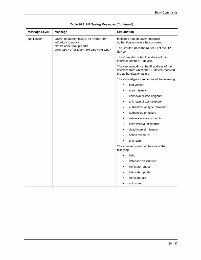
Show Commands
Notification OSPF intf authen failure, rid <router-id>, intf addr <ip-addr>, pkt src addr <src-ip-addr>, error type <error-type>, pkt type <pkt-type>
Indicates that an OSPF interface authentication failure has occurred.
The <router-id> is the router ID of the HP device.
The <ip-addr> is the IP address of the interface on the HP device.
The <src-ip-addr> is the IP address of the interface from which the HP device received the authentication failure.
The <error-type> can be one of the following:
• bad version
• area mismatch
• unknown NBMA neighbor
• unknown virtual neighbor
• authentication type mismatch
• authentication failure
• network mask mismatch
• hello interval mismatch
• dead interval mismatch
• option mismatch
• unknown
The <packet-type> can be one of the following:
• hello
• database description
• link state request
• link state update
• link state ack
• unknown
Table 20.1: HP Syslog Messages (Continued)
Message Level Message Explanation
20 - 47

Command Line Interface Reference
Notification OSPF virtual intf authen failure,rid <router-id>, intf addr <ip-addr>, pkt src addr <src-ip-addr>, error type <error-type>, pkt type <pkt-type>
Indicates that an OSPF virtual interface authentication failure has occurred.
The <router-id> is the router ID of the HP device.
The <ip-addr> is the IP address of the interface on the HP device.
The <src-ip-addr> is the IP address of the interface from which the HP device received the authentication failure.
The <error-type> can be one of the following:
• bad version
• area mismatch
• unknown NBMA neighbor
• unknown virtual neighbor
• authentication type mismatch
• authentication failure
• network mask mismatch
• hello interval mismatch
• dead interval mismatch
• option mismatch
• unknown
The <packet-type> can be one of the following:
• hello
• database description
• link state request
• link state update
• link state ack
• unknown
Table 20.1: HP Syslog Messages (Continued)
Message Level Message Explanation
20 - 48

Show Commands
Notification OSPF intf rcvd bad pkt, rid <router-id>, intf addr <ip-addr>, pkt src addr <src-ip-addr>, pkt type <pkt-type>
Indicates that an OSPF interface received a bad packet.
The <router-id> is the router ID of the HP device.
The <ip-addr> is the IP address of the interface on the HP device.
The <src-ip-addr> is the IP address of the interface from which the HP device received the authentication failure.
The <packet-type> can be one of the following:
• hello
• database description
• link state request
• link state update
• link state ack
• unknown
Notification OSPF virtual intf rcvd bad pkt, rid <router-id>, intf addr <ip-addr>, pkt src addr <src-ip-addr>, pkt type <pkt-type>
Indicates that an OSPF interface received a bad packet.
The <router-id> is the router ID of the HP device.
The <ip-addr> is the IP address of the interface on the HP device.
The <src-ip-addr> is the IP address of the interface from which the HP device received the authentication failure.
The <packet-type> can be one of the following:
• hello
• database description
• link state request
• link state update
• link state ack
• unknown
Table 20.1: HP Syslog Messages (Continued)
Message Level Message Explanation
20 - 49

Command Line Interface Reference
Notification OSPF intf retransmit, rid <router-id>, intf addr <ip-addr>, nbr rid <nbr-router-id>,pkt type is <pkt-type>, LSA type <lsa-type>,LSA id <lsa-id>, LSA rid <lsa-router-id>
An OSPF interface on the HP device has retransmitted a Link State Advertisement (LSA).
The <router-id> is the router ID of the HP device.
The <ip-addr> is the IP address of the interface on the HP device.
The <nbr-router-ID> is the router ID of the neighbor router.
The <packet-type> can be one of the following:
• hello
• database description
• link state request
• link state update
• link state ack
• unknown
The <lsa-type> is the type of LSA.
The <lsa-id> is the LSA ID.
The <lsa-router-id> is the LSA router ID.
Table 20.1: HP Syslog Messages (Continued)
Message Level Message Explanation
20 - 50
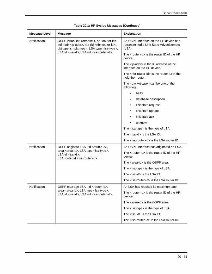
Show Commands
Notification OSPF virtual intf retransmit, rid <router-id>, intf addr <ip-addr>, nbr rid <nbr-router-id>, pkt type is <pkt-type>, LSA type <lsa-type>,LSA id <lsa-id>, LSA rid <lsa-router-id>
An OSPF interface on the HP device has retransmitted a Link State Advertisement (LSA).
The <router-id> is the router ID of the HP device.
The <ip-addr> is the IP address of the interface on the HP device.
The <nbr-router-id> is the router ID of the neighbor router.
The <packet-type> can be one of the following:
• hello
• database description
• link state request
• link state update
• link state ack
• unknown
The <lsa-type> is the type of LSA.
The <lsa-id> is the LSA ID.
The <lsa-router-id> is the LSA router ID.
Notification OSPF originate LSA, rid <router-id>, area <area-id>, LSA type <lsa-type>, LSA id <lsa-id>, LSA router id <lsa-router-id>
An OSPF interface has originated an LSA.
The <router-id> is the router ID of the HP device.
The <area-id> is the OSPF area.
The <lsa-type> is the type of LSA.
The <lsa-id> is the LSA ID.
The <lsa-router-id> is the LSA router ID.
Notification OSPF max age LSA, rid <router-id>, area <area-id>, LSA type <lsa-type>, LSA id <lsa-id>, LSA rid <lsa-router-id>
An LSA has reached its maximum age.
The <router-id> is the router ID of the HP device.
The <area-id> is the OSPF area.
The <lsa-type> is the type of LSA.
The <lsa-id> is the LSA ID.
The <lsa-router-id> is the LSA router ID.
Table 20.1: HP Syslog Messages (Continued)
Message Level Message Explanation
20 - 51

Command Line Interface Reference
Notification OSPF LSDB overflow, rid <router-id>, limit <num>
A Link State Database Overflow (LSDB) condition has occurred.
The <router-id> is the router ID of the HP device.
The <num> is the number of LSAs.
Notification OSPF LSDB approaching overflow, rid <router-id>, limit <num>
The software is close to an LSDB overflow condition.
The <router-id> is the router ID of the HP device.
The <num> is the number of LSAs.
Notification SRP intf state changed, intf <portnum>, addr <ip-addr>, state <srp-state>
A state change has occurred in an HP Standby Router Protocol (SRP) interface.
The <portnum> is the port.
The <ip-addr> is the IP address of the SRP interface.
The <srp-state> can be one of the following:
• init
• negotiating
• standby
• active
• unknown
Notification VRRP intf state changed, intf <portnum>, vrid <virtual-router-id>,state <vrrp-state>
A state change has occurred in a Virtual Router Redundancy Protocol (VRRP) interface.
The <portnum> is the port.
The <virtual-router-id> is the virtual router ID (VRID) configured on the interface.
The <vrrp-state> can be one of the following:
• init
• master
• backup
• unknown
Notification BGP Peer <ip-addr> UP (ESTABLISHED) Indicates that a BGP4 neighbor has come up.
The <ip-addr> is the IP address of the neighbor’s BGP4 interface with the HP device.
Table 20.1: HP Syslog Messages (Continued)
Message Level Message Explanation
20 - 52

Show Commands
Notification BGP Peer <ip-addr> DOWN (IDLE) Indicates that a BGP4 neighbor has gone down.
The <ip-addr> is the IP address of the neighbor’s BGP4 interface with the HP device.
Informational Cold start The device has been powered on.
Informational Warm start The system software (flash code) has been reloaded.
Informational <user-name> login to USER EXEC mode A user has logged into the USER EXEC mode of the CLI.
The <user-name> is the user name.
Informational <user-name> logout from USER EXEC mode
A user has logged out of the USER EXEC mode of the CLI.
The <user-name> is the user name.
Informational <user-name> login to PRIVILEGE mode A user has logged into the Privileged EXEC mode of the CLI.
The <user-name> is the user name.
Informational <user-name> logout from PRIVILEGE mode A user has logged out of Privileged EXEC mode of the CLI.
The <user-name> is the user name.
Informational SNMP Auth. failure, intruder IP: <ip-addr> A user has tried to open a management session with the device using an invalid SNMP community string.
The <ip-addr> is the IP address of the host that sent the invalid community string.
Informational Interface <portnum>, state up A port has come up.
The <portnum> is the port number.
Informational Interface <portnum>, state down A port has gone down.
The <portnum> is the port number.
Informational Bridge root changed, vlan <vlan-id>, new root ID <string>, root interface <portnum>
A Spanning Tree Protocol (STP) topology change has occurred.
The <vlan-id> is the ID of the VLAN in which the STP topology change occurred.
The <root-id> is the STP bridge root ID.
The <portnum> is the number of the port connected to the new root bridge.
Table 20.1: HP Syslog Messages (Continued)
Message Level Message Explanation
20 - 53

Command Line Interface Reference
EXAMPLE:
This example show some common Syslog messages.
HP9300# show loggingSyslog logging: enabled (0 messages dropped, 0 flushes, 0 overruns) Buffer logging: level ACDMEINW, 7 messages logged level code: A=alert C=critical D=debugging M=emergency E=error I=informational N=notification W=warning
Static Log Buffer:
Dynamic Log Buffer (50 entries):00d05h44m28s:info:Interface e3/11, state up00d05h44m28s:info:Bridge topology change, vlan 1, interface 3/11, changed stateto forwarding00d04h45m49s:info:Interface e3/11, state down00d04h45m20s:info:Interface e3/11, state up00d04h45m20s:info:Bridge topology change, vlan 1, interface 3/11, changed stateto forwarding
Informational Bridge is new root, vlan <vlan-id>, root ID <root-id>
A Spanning Tree Protocol (STP) topology change has occurred, resulting in the HP device becoming the root bridge.
The <vlan-id> is the ID of the VLAN in which the STP topology change occurred.
The <root-id> is the STP bridge root ID.
Informational Bridge topology change, vlan <vlan-id>, interface <portnum>, changed state to <stp-state>
A Spanning Tree Protocol (STP) topology change has occurred on a port.
The <vlan-id> is the ID of the VLAN in which the STP topology change occurred.
The <portnum> is the port number.
The <stp-state> is the new STP state and can be one of the following:
• disabled
• blocking
• listening
• learning
• forwarding
• unknown
Informational startup-config was changed
or
startup-config was changed by <user-name>
A configuration change was saved to the startup-config file.
The <user-name> is the user’s ID, if they entered a user ID to log in.
Debug BGP4: Not enough memory available to run BGP4
The device could not start the BGP4 routing protocol because there is not enough memory available.
Table 20.1: HP Syslog Messages (Continued)
Message Level Message Explanation
20 - 54

Show Commands
00d01h45m13s:info:Interface e3/11, state down00d00h01m00s:info:Interface e3/11, state up00d00h00m05s:info:Bridge topology change, vlan 1, interface 3/11, changed stateto forwarding00d00h00m00s:info:Warm start
EXAMPLE:
This example shows log entries for authentication failures. If someone enters an invalid community string when attempting to access the SNMP server on the HP device, the device generates a trap in the device’s syslog buffer. (If you have configured the device to use a third-party SyslogD server, the device also sends a log entry to the server.)
Here is an example of a log that contains SNMP authentication traps. In this example, someone attempted to access the HP device three times using invalid SNMP community strings. The unsuccessful attempts indicate either an authorized user who is also a poor typist, or an unauthorized user who is attempting to access the device.
HP9300(config)# show logSyslog logging: enabled (0 messages dropped, 0 flushes, 1 overruns)Buffer logging: level ACDMEINW, 50 messages loggedlevel code: A=alert C=critical D=debugging M=emergency E=errorI=informational N=notification W=warning
Static Log Buffer:
Dynamic Log Buffer (50 entries):00d01h45m13s:info:SNMP Authentication failure, intruder IP: 207.95.6.5500d00h01m00s:info:SNMP Authentication failure, intruder IP: 207.95.6.5500d00h00m05s:info:SNMP Authentication failure, intruder IP: 207.95.6.55
EXAMPLE:
This example shows a log entry for an IP address conflict between the HP device and another device on the network.
In addition to placing an entry in the log, the software sends a log message to the SyslogD server, if you have configured one, and sends a message to each open CLI session.
HP9300(config)# show logSyslog logging: enabled (0 messages dropped, 0 flushes, 1 overruns)Buffer logging: level ACDMEINW, 50 messages loggedlevel code: A=alert C=critical D=debugging M=emergency E=errorI=informational N=notification W=warning
Static Log Buffer:
Dynamic Log Buffer (50 entries):00d01h45m13s:warning:Duplicate IP address 209.157.23.188 detected,sent from MAC address 00e0.5201.3bc9 coming from port 7/7
EXAMPLE:
Here are some examples of log entries for packets denied by Access Control Lists (ACLs).
NOTE: On devices that also use Layer 2 MAC filters, both types of log entries can appear in the same log. Only ACL log entries are shown in this example.
20 - 55
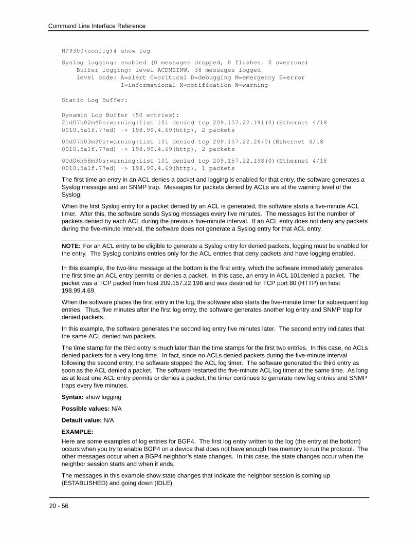
Command Line Interface Reference
HP9300(config)# show log
Syslog logging: enabled (0 messages dropped, 0 flushes, 0 overruns) Buffer logging: level ACDMEINW, 38 messages logged level code: A=alert C=critical D=debugging M=emergency E=error I=informational N=notification W=warning
Static Log Buffer:
Dynamic Log Buffer (50 entries):21d07h02m40s:warning:list 101 denied tcp 209.157.22.191(0)(Ethernet 4/18 0010.5a1f.77ed) -> 198.99.4.69(http), 2 packets
00d07h03m30s:warning:list 101 denied tcp 209.157.22.26(0)(Ethernet 4/18 0010.5a1f.77ed) -> 198.99.4.69(http), 2 packets
00d06h58m30s:warning:list 101 denied tcp 209.157.22.198(0)(Ethernet 4/18 0010.5a1f.77ed) -> 198.99.4.69(http), 1 packets
The first time an entry in an ACL denies a packet and logging is enabled for that entry, the software generates a Syslog message and an SNMP trap. Messages for packets denied by ACLs are at the warning level of the Syslog.
When the first Syslog entry for a packet denied by an ACL is generated, the software starts a five-minute ACL timer. After this, the software sends Syslog messages every five minutes. The messages list the number of packets denied by each ACL during the previous five-minute interval. If an ACL entry does not deny any packets during the five-minute interval, the software does not generate a Syslog entry for that ACL entry.
NOTE: For an ACL entry to be eligible to generate a Syslog entry for denied packets, logging must be enabled for the entry. The Syslog contains entries only for the ACL entries that deny packets and have logging enabled.
In this example, the two-line message at the bottom is the first entry, which the software immediately generates the first time an ACL entry permits or denies a packet. In this case, an entry in ACL 101denied a packet. The packet was a TCP packet from host 209.157.22.198 and was destined for TCP port 80 (HTTP) on host 198.99.4.69.
When the software places the first entry in the log, the software also starts the five-minute timer for subsequent log entries. Thus, five minutes after the first log entry, the software generates another log entry and SNMP trap for denied packets.
In this example, the software generates the second log entry five minutes later. The second entry indicates that the same ACL denied two packets.
The time stamp for the third entry is much later than the time stamps for the first two entries. In this case, no ACLs denied packets for a very long time. In fact, since no ACLs denied packets during the five-minute interval following the second entry, the software stopped the ACL log timer. The software generated the third entry as soon as the ACL denied a packet. The software restarted the five-minute ACL log timer at the same time. As long as at least one ACL entry permits or denies a packet, the timer continues to generate new log entries and SNMP traps every five minutes.
Syntax: show logging
Possible values: N/A
Default value: N/A
EXAMPLE:
Here are some examples of log entries for BGP4. The first log entry written to the log (the entry at the bottom) occurs when you try to enable BGP4 on a device that does not have enough free memory to run the protocol. The other messages occur when a BGP4 neighbor’s state changes. In this case, the state changes occur when the neighbor session starts and when it ends.
The messages in this example show state changes that indicate the neighbor session is coming up (ESTABLISHED) and going down (IDLE).
20 - 56
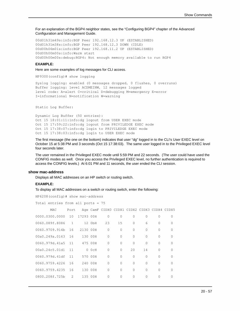
Show Commands
For an explanation of the BGP4 neighbor states, see the “Configuring BGP4” chapter of the Advanced Configuration and Management Guide.
00d01h31m49s:info:BGP Peer 192.168.12.3 UP (ESTABLISHED)00d01h31m38s:info:BGP Peer 192.168.12.3 DOWN (IDLE)00d00h06m01s:info:BGP Peer 192.168.11.2 UP (ESTABLISHED)00d00h00m00s:info:Warm start00d00h00m00s:debug:BGP4: Not enough memory available to run BGP4
EXAMPLE:
Here are some examples of log messages for CLI access.
HP9300(config)# show logging
Syslog logging: enabled (0 messages dropped, 0 flushes, 0 overruns)Buffer logging: level ACDMEINW, 12 messages loggedlevel code: A=alert C=critical D=debugging M=emergency E=error I=informational N=notification W=warning
Static Log Buffer:
Dynamic Log Buffer (50 entries):Oct 15 18:01:11:info:dg logout from USER EXEC modeOct 15 17:59:22:info:dg logout from PRIVILEDGE EXEC modeOct 15 17:38:07:info:dg login to PRIVILEDGE EXEC modeOct 15 17:38:03:info:dg login to USER EXEC mode
The first message (the one on the bottom) indicates that user “dg” logged in to the CLI’s User EXEC level on October 15 at 5:38 PM and 3 seconds (Oct 15 17:38:03). The same user logged in to the Privileged EXEC level four seconds later.
The user remained in the Privileged EXEC mode until 5:59 PM and 22 seconds. (The user could have used the CONFIG modes as well. Once you access the Privileged EXEC level, no further authentication is required to access the CONFIG levels.) At 6:01 PM and 11 seconds, the user ended the CLI session.
show mac-addressDisplays all MAC addresses on an HP switch or routing switch.
EXAMPLE:
To display all MAC addresses on a switch or routing switch, enter the following:
HP6208(config)# show mac-address
Total entries from all ports = 75
MAC Port Age CamF CIDX0 CIDX1 CIDX2 CIDX3 CIDX4 CIDX5
0000.0300.0000 10 17293 00H 0 0 0 0 0 0
0060.089f.8086 1 12 0bH 23 15 0 6 0 0
0060.9709.914b 16 2130 00H 0 0 0 0 0 0
00a0.249a.0163 16 130 00H 0 0 0 0 0 0
0060.979d.41a5 11 475 00H 0 0 0 0 0 0
00a0.24c5.01d1 11 0 0cH 0 0 20 14 0 0
0060.979d.41df 11 570 00H 0 0 0 0 0 0
0060.9759.4226 16 240 00H 0 0 0 0 0 0
0060.9759.4235 16 130 00H 0 0 0 0 0 0
0800.208f.725b 2 135 00H 0 0 0 0 0 0
20 - 57

Command Line Interface Reference
0060.9759.4264 16 0 0aH 0 14 0 21 0 0
00a0.24c5.02a1 16 15 09H 5 0 0 33 0 0
0000.c02c.a2bf 7 11 03H 27 5 0 0 0 0
00a0.24c5.02f8 4 135 00H 0 0 0 0 0 0
00a0.24c5.02fc 6 0 06H 0 8 31 0 0 0
0800.207e.c312 2 2 0dH 25 0 24 13 0 0
0800.208f.5331 2 135 00H 0 0 0 0 0 0
00e0.5200.0385 10 5160 00H 0 0 0 0 0 0
00e0.5200.0388 10 35420 00H 0 0 0 0 0 0
0000.f820.a3ad 3 11239 00H 0 0 0 0 0 0
0000.c06f.d3be 3 135 00H 0 0 0 0 0 0
--More--, next page: Space/Return key, quit: Control-c
NOTE: The information displayed in columns with headings, CamF, and CIDX0 through CIDX5, is not relevant for day-to-day management of the switch or routing switch. The information is used by engineering and technical support staff for debug purposes.
Syntax: show mac-address [ethernet <portnum> | session | statistics | <mac-addr>]
The ethernet <portnum> option displays the MAC address(es) on the specified port.
The session parameter displays the MAC session table.
The statistics option displays statistics. See “show mac-address statistics” on page 20-58.
The <mac-addr> option displays information about the specified MAC address. Specify the MAC address in the following format: abcd.egh.1234. (Separate each four bytes with a period.)
Possible values: see above
Default value: N/A
show mac-address statisticsDisplays the total number of MAC addresses currently active on an HP switch or routing switch. This command serves as a numerical summary of the detailed summary provided by the command show mac-address.
For each port, the number of learned MAC addresses is displayed.
EXAMPLE:
HP9300(config)# show mac-address statistics
Total entries = 41
Port 1 2 3 4 5 6 7 8 9
0 6 11 1 1 1 2 1 1
Port 10 11 12 13 14 15 16
0 3 1 3 1 1 8
Syntax: show mac-address statistics
Possible values: N/A
Default value: N/A
20 - 58

Show Commands
show mediaShows the type of ports active on a Chassis device.
EXAMPLE:
HP9300(config)# show media
1/1:SX 1/2:SX 1/3:SX 1/4:SX
2/1:SX 2/2:SX 2/3:SX 2/4:SX 2/5:SX 2/6:SX 2/7:SX 2/8:SX
3/1:SX 3/2:SX 3/3:SX 3/4:SX 3/5:SX 3/6:SX 3/7:SX 3/8:SX
4/1:SX 4/2:SX 4/3:SX 4/4:SX 4/5:SX 4/6:SX 4/7:SX 4/8:SX
6/1:SX 6/2:SX 6/3:SX 6/4:SX 6/5:SX 6/6:SX 6/7:SX 6/8:SX
7/1:SX 7/2:SX 7/3:SX 7/4:SX 7/5:SX 7/6:SX 7/7:SX 7/8:SX
8/1:SX 8/2:SX 8/3:SX 8/4:SX 8/5:SX 8/6:SX 8/7:SX 8/8:SX
Syntax: show media
Possible values: N/A
Default value: N/A
show moduleShows the types of modules installed on a Chassis device.
EXAMPLE:
Here is an example of the command’s display output on an HP 9308M routing switch.
HP9300# show module
Module Status Ports Starting MAC
S1: B8GM Fiber Management Module OK 8 00e0.52f0.5a00
S2: B24E Copper Switch Module OK 24 00e0.52f0.5a20
S3: B24E Copper Switch Module OK 24 00e0.52f0.5a40
S4: B24E Copper Switch Module OK 24 00e0.52f0.5a60
S5: B8G Fiber Switch Module OK 8 00e0.52f0.5a00
S6: B24E Copper Switch Module OK 24 00e0.52f0.5aa0
S7: B8G Fiber Switch Module OK 8 00e0.52f0.5a00
S8: B8G Fiber Switch Module OK 8 00e0.52f0.5a00
Possible values: N/A
Default value: N/A
show priority-mappingDisplays the queues to which the 802.1p priorities are assigned.
EXAMPLE:
To display the queue assignments for all the priorities, enter the following command at any level of the CLI:
HP9300(config)# show priority-mapping all802.1p priority 0 mapped to qos profile qosp0802.1p priority 1 mapped to qos profile qosp0802.1p priority 2 mapped to qos profile qosp1802.1p priority 3 mapped to qos profile qosp1
20 - 59
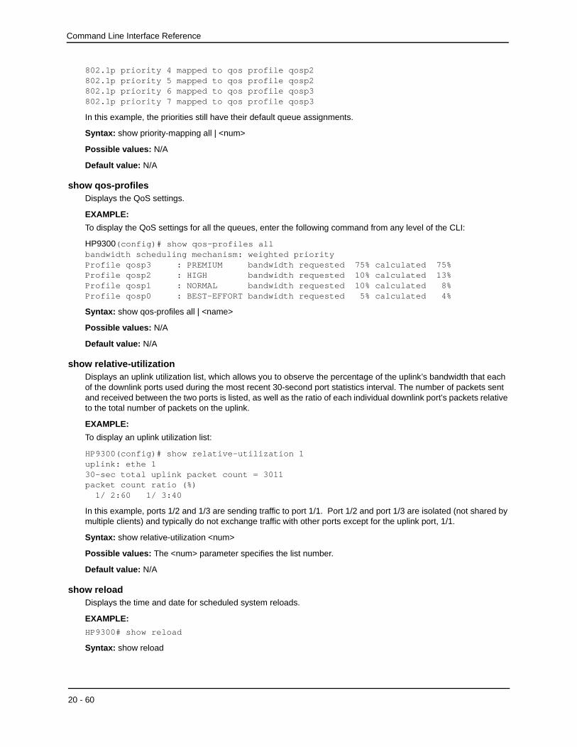
Command Line Interface Reference
802.1p priority 4 mapped to qos profile qosp2802.1p priority 5 mapped to qos profile qosp2802.1p priority 6 mapped to qos profile qosp3802.1p priority 7 mapped to qos profile qosp3
In this example, the priorities still have their default queue assignments.
Syntax: show priority-mapping all | <num>
Possible values: N/A
Default value: N/A
show qos-profilesDisplays the QoS settings.
EXAMPLE:
To display the QoS settings for all the queues, enter the following command from any level of the CLI:
HP9300(config)# show qos-profiles allbandwidth scheduling mechanism: weighted priorityProfile qosp3 : PREMIUM bandwidth requested 75% calculated 75%Profile qosp2 : HIGH bandwidth requested 10% calculated 13%Profile qosp1 : NORMAL bandwidth requested 10% calculated 8%Profile qosp0 : BEST-EFFORT bandwidth requested 5% calculated 4%
Syntax: show qos-profiles all | <name>
Possible values: N/A
Default value: N/A
show relative-utilizationDisplays an uplink utilization list, which allows you to observe the percentage of the uplink’s bandwidth that each of the downlink ports used during the most recent 30-second port statistics interval. The number of packets sent and received between the two ports is listed, as well as the ratio of each individual downlink port’s packets relative to the total number of packets on the uplink.
EXAMPLE:
To display an uplink utilization list:
HP9300(config)# show relative-utilization 1 uplink: ethe 130-sec total uplink packet count = 3011packet count ratio (%) 1/ 2:60 1/ 3:40
In this example, ports 1/2 and 1/3 are sending traffic to port 1/1. Port 1/2 and port 1/3 are isolated (not shared by multiple clients) and typically do not exchange traffic with other ports except for the uplink port, 1/1.
Syntax: show relative-utilization <num>
Possible values: The <num> parameter specifies the list number.
Default value: N/A
show reloadDisplays the time and date for scheduled system reloads.
EXAMPLE:
HP9300# show reload
Syntax: show reload
20 - 60
Show Commands
Possible values: N/A
Default value: N/A
show rmon alarmDisplays any reported RMON alarms for the system.
EXAMPLE:
HP9300# show rmon alarm
Alarm table is empty
Syntax: show rmon alarm [<alarm-table-entry>]
Possible values: N/A
Default value: N/A
show rmon eventDisplays any reported RMON events for the system.
EXAMPLE:
HP9300# show rmon event
Event table is empty
Syntax: show rmon event [<event-table-entry>]
Possible values: N/A
Default value: N/A
show rmon historyDisplays the RMON history for the system.
EXAMPLE:
HP9300# show rmon historyHistory 1 is active, owned by monitor Monitors interface 1/1 (ifIndex 1) every 30 seconds 25 buckets were granted to store statistics History 2 is active, owned by monitor Monitors interface 1/1 (ifIndex 1) every 1800 seconds 25 buckets were granted to store statistics History 3 is active, owned by monitor Monitors interface 5/20 (ifIndex 148) every 30 seconds 25 buckets were granted to store statistics History 4 is active, owned by monitor Monitors interface 5/20 (ifIndex 148) every 1800 seconds 25 buckets were granted to store statistics
Syntax: show rmon history [<control-table-entry>]
Possible values: N/A
Default value: N/A
show rmon statisticsDisplays detailed statistics for each port.
EXAMPLE:
HP9300# sh rmon st
20 - 61

Command Line Interface Reference
Syntax: show rmon statistics [ethernet <portnum>] | [<num>]
The ethernet <portnum> parameter displays the RMON port statistics for the specified port.
The <num> parameter displays the specified entry. Entries are numbered beginning with 1.
Possible values: see above
Default value: N/A
show running-configDisplays the running configuration of the HP switch or routing switch on the terminal screen.
NOTE: This command is equivalent to the write terminal command.
EXAMPLE:
HP9300# sh run
Syntax: show running-config
NOTE: If you have enabled the display of passwords with the enable password-display CONFIG command, SNMP community strings and passwords are displayed when you enter the show running-config command in Privileged EXEC mode, but not in User EXEC mode.
Possible values: N/A
Default value: N/A
show serverDisplays configuration information and statistics for a web server address you added using the server real-name command.
This command applies only to routing switches you have configured to assist third-party Server Load Balancers or directly connected web servers with globally-distributed Server Load Balancing (SLB). See the “Route Health Injection” chapter of the Advanced Configuration and Management Guide.
EXAMPLE:
HP9300# show server real tinman
Real Servers Info
Server State - 1:enabled, 2:failed, 3:test, 4:suspect, 5:grace_dn, 6:activeName:tinman IP: 209.157.23.60:4 State:1
Syntax: show server real <name> | keepalive-port
See the “Route Health Injection” chapter of the Advanced Configuration and Management Guide for an explanation of the fields in this display.
Possible values: N/A
Default value: N/A
show snmp serverLists system administrative information—contact name, system location, community strings, and traps enabled for an HP switch or routing switch.
EXAMPLE:
HP9300# show snmp server
Contact: Marshall
Location: Copy Center
20 - 62

Show Commands
Community(ro): public
Community(rw): private
Traps
Cold start: Enable
Link up: Enable
Link down: Enable
Authentication: Enable
[ ..........]
Total Trap-Receiver Entries: 4
Trap-Receiver IP Address Community
1 207.95.6.211
2 207.95.5.21
Syntax: show snmp server
Possible values: N/A
Default value: N/A
show spanDisplays spanning tree statistics such as root cost, root port, and priority.
EXAMPLE:
HP9300# show span
Global STP Parameters:
VLAN Root Root Root Prio Max He- Ho- Fwd Last Chg Bridge
ID ID Cost Port rity Age llo ld dly Chang cnt Address
Hex sec sec sec sec sec
1 800000e052801400 0 Root 8000 20 2 2 15 0 1 00e052801400
Port STP Parameters:
VLAN Port Prio Path State Fwd Design Design Design
ID Num rity Cost Trans Cost Root Bridge
Hex
1 1/1 80 1 FORWARDING 1 0 800000e052801400 800000e052801400
1 1/2 80 0 DISABLED 0 0 0000000000000000 0000000000000000
1 2/1 80 0 DISABLED 0 0 0000000000000000 0000000000000000
1 2/3 80 0 DISABLED 0 0 0000000000000000 0000000000000000
1 2/5 80 0 DISABLED 0 0 0000000000000000 0000000000000000
Syntax: show span
Possible values: N/A
Default value: N/A
20 - 63

Command Line Interface Reference
show span vlanDisplays global and port STP information for a given VLAN on an HP switch or routing switch.
EXAMPLE:
HP9300# show span vlan 2
Global Bridge Parameters:
VLAN Root Root Root Prio Max He- Ho- Fwd Last Chg Bridge
ID ID Cost Port rity Age llo ld dly Chang cnt Address
Hex sec sec sec
2 800000e0520002f5 0 Root 8000 20 2 2 15 0 0 00e0520002f5
Port STP Parameters:
VLAN Port Prio Path State Fwd Design Design Design
ID Num rity Cost Trans Cost Root Bridge
Hex
2 1 0080 0 DISABLED 0 0000000000000000 0000000000000000
2 2 0080 0 DISABLED 0 0000000000000000 0000000000000000
2 3 0080 0 DISABLED 0 0000000000000000 0000000000000000
2 4 0080 0 DISABLED 0 0000000000000000 0000000000000000
2 5 0080 0 DISABLED 0 0000000000000000 0000000000000000
Syntax: show span vlan <vlan-id>
Possible values: N/A
Default value: N/A
show statisticsDisplays port statistics for an HP switch or routing switch (transmit, receive, collisions, errors).
EXAMPLE:
HP9300# show statistics
Buffer Manager Queue
[Pkt Receive Pkt Transmit]
0 0
Port Counters: Packets Collisions Errors
Port [Receive Transmit] [Receive Transmit] [Align FCS Giant Short]
1/1 15935 5443 0 0 0 0 0 0
1/2 0 0 0 0 0 0 0 0
1/3 0 0 0 0 0 0 0 0
1/4 0 0 0 0 0 0 0 0
2/1 0 0 0 0 0 0 0 0
20 - 64

Show Commands
2/2 0 0 0 0 0 0 0 0
2/3 0 0 0 0 0 0 0 0
2/4 0 0 0 0 0 0 0 0
2/5 0 0 0 0 0 0 0 0
2/6 0 0 0 0 0 0 0 0
2/7 0 0 0 0 0 0 0 0
2/8 0 0 0 0 0 0 0 0
Syntax: show statistics [ethernet <portnum>] | [slot <slot-num>]
The ethernet <portnum> parameter displays statistics for a specific port.
The slot <slot-num> parameter displays statistics for a specific chassis slot.
NOTE: The slot <slot-num> parameter applies only to the HP 9304M or HP 9308M.
Possible values: N/A
Default value: N/A
show techShows technical details to you for assistance in troubleshooting issues when working with technical support. The information shown is a sub-set of all the available information.
EXAMPLE:
HP9300# show tech
show tech
SW: Version 6.1.00T41 Copyright (c) 1996-1998 Hewlett-Packard
Compiled on Oct 13 1999 at 22:54:22 labeled as S0420012
HW: Chassis HP 9308M
==========================================================================
SL 1: 4 Port Gig Management Module
2048 KB BRAM, SMC version 1, ICBM version 20
384 KB PRAM(256K+128K) and 2048*8 CAM entries for DMA 0, version 0209
384 KB PRAM(256K+128K) and shared CAM entries for DMA 1, version 0209
==========================================================================
SL 2: 8 Port Gig Module
2048 KB BRAM, SMC version 1, ICBM version 20
384 KB PRAM(256K+128K) and 2048*8 CAM entries for DMA 4, version 0206
384 KB PRAM(256K+128K) and shared CAM entries for DMA 5, version 0206
384 KB PRAM(256K+128K) and 2048*8 CAM entries for DMA 6, version 0206
384 KB PRAM(256K+128K) and shared CAM entries for DMA 7, version 0206
==========================================================================
240 MHz Power PC processor 603 (revision 7) 66 MHz bus
128 KB boot flash memory
4096 KB code flash memory
20 - 65

Command Line Interface Reference
256 KB SRAM
32756 KB DRAM
The system uptime is 1 hours 18 minutes 20 seconds
HP9300#Port Link State Dupl Speed Trunk Tag Priori MAC
1/1 Up Forward Full 1G None No level0 00e0.5280.1400 1/1
1/2 Down None None None None No level0 00e0.5280.1401 1/2
[. . . . . . . . .]
The system had been up for 422 minutes
General Registers:
04208278 0425f358 0421c200 00009030 00000000 00000000 000000ff 044b94e8
[. . . . . . . . .]
Syntax: show tech
Possible values: N/A
Default value: N/A
show telnetShows the IP address of the station with the active Telnet session. Up to five read-only access Telnet sessions are supported on the HP switch or routing switch at one time. Write access through Telnet is limited to one session.
EXAMPLE:
HP9300# show telnet
Telnet connection: Yes
client IP address: 207.95.6.18
Telnet connection: No
Telnet connection: No
Telnet connection: No
Telnet connection: No
Syntax: show telnet
Possible values: N/A
Default value: N/A
show trunkDisplays trunk groups and their port membership for HP switches and routing switches.
EXAMPLE:
HP9300(config-if)# show trunk
Configured trunks:
Trunk Group Ports
1 1 2 3
Operational trunks:
Trunk Group Ports Duplex Speed Tag Priority
1 1 2 3 Full 100M No High
20 - 66

Show Commands
Syntax: show trunk
Possible values: N/A
Default value: N/A
show usersLists the local access user accounts configured on the device.
EXAMPLE:
HP9300# sh u
Username Password Encrypt Privilege=======================================================================MattBerto $1$$arc/3B93fBJdrtj/DmGWt1 enabled 0DanGreenwell $2$$arc/3B93fBJdrtj/DmGWt2 enabled 0AlexMaynes $3$$arc/3B93fBJdrtj/DmGWt3 enabled 0
Syntax: show users
Possible values: N/A
Default value: N/A
show versionLists software, hardware and firmware details for an HP switch or routing switch. Much of the information displayed by this command can be used by HP technical support to help identify your system if you need help to resolve an issue. The following information might be particularly useful and is highlighted in bold type in the example:
• Software version – The version number of the software. This is the number referred to in release notes and other product documentation.
• Software label – The name of the software image file. This is the name of the file you install into the device’s flash memory. Note that the same software version usually has different software labels depending on the product and in come cases on the contents of the software.
• DRAM – the amount of memory on the device. This memory amount can be important if you want to use memory-intensive features such as Border Gateway Protocol version 4 (BGP4).
EXAMPLE:
This example shows the command output on an HP 9308M running software version 05.0.00.
HP9300# sh ver
SW: Version 05.2.16T43 Hewlett-Packard Company
Compiled on Oct 1 1999 at 19:28:56 labeled as HPR05216
J4138A HP ProCurve Routing Switch 9308M
HW: ProCurve HP9308 Routing Switch, SYSIF version 10
==========================================================================
SL 1: 8 Port Gig Management Module
2048 KB BRAM, SMC version 1, ICBM version 21
256 KB PRAM(256K+0K) and 2048*8 CAM entries for DMA 0, version 0209
256 KB PRAM(256K+0K) and shared CAM entries for DMA 1, version 0209
256 KB PRAM(256K+0K) and 2048*8 CAM entries for DMA 2, version 0209
256 KB PRAM(256K+0K) and shared CAM entries for DMA 3, version 0209
==========================================================================
20 - 67

Command Line Interface Reference
SL 3: 24 Port Copper Module
2048 KB BRAM, SMC version 2, ICBM version 21
256 KB PRAM(256K+0K) and 2048*8 CAM entries for DMA 8, version 0808
256 KB PRAM(256K+0K) and shared CAM entries for DMA 9, version 0808
256 KB PRAM(256K+0K) and shared CAM entries for DMA 10, version 0808
==========================================================================
SL 4: 8 Port Gig Module
2048 KB BRAM, SMC version 1, ICBM version 21
256 KB PRAM(256K+0K) and 2048*8 CAM entries for DMA 12, version 0209
256 KB PRAM(256K+0K) and shared CAM entries for DMA 13, version 0209
256 KB PRAM(256K+0K) and 2048*8 CAM entries for DMA 14, version 0209
256 KB PRAM(256K+0K) and shared CAM entries for DMA 15, version 0209
==========================================================================
SL 7: 24 Port Copper Module
2048 KB BRAM, SMC version 2, ICBM version 21
256 KB PRAM(256K+0K) and 2048*8 CAM entries for DMA 24, version 0808
256 KB PRAM(256K+0K) and shared CAM entries for DMA 25, version 0808
256 KB PRAM(256K+0K) and shared CAM entries for DMA 26, version 0808
==========================================================================
240 MHz Power PC processor 603 (revision 7) 63 MHz bus
128 KB boot flash memory
4096 KB code flash memory
256 KB SRAM
32 MB DRAM
The system uptime is 1 hours 14 minutes 37 seconds
The system started at 05:15:56 Pacific Tue Feb 01 2000
Syntax: show version
Possible values: N/A
Default value: N/A
show vlansDisplays the VLANs configured on the system, their member ports, assigned priority, and STP status.
EXAMPLE:
HP9300(config)# show vlans
Total PORT-VLAN entries: 2Maximum PORT-VLAN entries: 8legend: [S=Slot]
PORT-VLAN 1, Name DEFAULT-VLAN, Priority level0, Spanning tree Off Untagged Ports: (S2) 1 2 3 4 5 6 7 8 9 10 11 12 13 14 15 16 Untagged Ports: (S2) 17 18 19 20 21 22 23 24 Untagged Ports: (S4) 1 2 3 4 5 6 7 8 9 10 11 12 13 14 15 16
20 - 68

Show Commands
Untagged Ports: (S4) 17 18 19 20 21 22 23 24 Tagged Ports: None
PORT-VLAN 10, Name IP_VLAN, Priority level0, Spanning tree Off Untagged Ports: (S1) 1 2 3 4 5 6 Tagged Ports: None
IP-subnet VLAN 1.1.1.0 255.255.255.0, Dynamic port enabled Name: Mktg-LAN Static ports: None Exclude ports: None Dynamic ports: (S1) 1 2 3 4 5 6 PORT-VLAN 20, Name IPX_VLAN, Priority level0, Spanning tree Off Untagged Ports: (S2) 1 2 3 4 5 6 Tagged Ports: None
IPX-network VLAN 0000ABCD, frame type ethernet_ii, Dynamic port enabled Name: Eng-LAN Static ports: None Exclude ports: None Dynamic ports: (S2) 1 2 3 4 5 6
Syntax: show vlans [<vlan-id> | ethernet <portnum>]
The <vlan-id> parameter specifies a VLAN for which you want to display the configuration information.
The ethernet <portnum> parameter specifies a port. If you use this parameter, the command lists all the VLAN memberships for the port.
Possible values: N/A
Default value: N/A
show web-connectionDisplays the access levels and IP addresses of the devices that currently have Web management interface sessions with the device.
To clear all sessions displayed by this command, see “clear web-connection” on page 5-7.
EXAMPLE:
HP9300(config)# show web-connection
User IP address
set 10.10.11.150
Syntax: show web-connection
Possible values: N/A
Default value: N/A
show whoLists the active console and Telnet CLI sessions.
EXAMPLE:
HP9300# show whoConsole connections: establishedTelnet connections: 1 established, client ip address 209.157.22.63 2 closed 3 closed
20 - 69

Command Line Interface Reference
4 closed 5 closed
Syntax: show who
Possible values: N/A
Default value: N/A
20 - 70