chapter 22 materials and construction … · chapter 22 – materials and construction...
TRANSCRIPT

Larimer County Urban Area Street Standards – Revised February 17, 2015
Adopted by Larimer County, City of Loveland, City of Fort Collins
Page 22-i
CHAPTER 22 – MATERIALS AND CONSTRUCTION SPECIFICATIONS
TABLE OF CONTENTS
Section Title Page
22.1 Right-of-Way Grading ................................................................................................ 22-1
22.1.1 Site Remediation ........................................................................................................................ 22-1
A. Disposal of Waste Materials ................................................................................................. 22-1
22.1.2 Site Demolition ........................................................................................................................... 22-1
A. Removal of structures and Obstructions ............................................................................... 22-1
22.1.3 Site Clearing and Grubbing ...................................................................................................... 22-2
A. General ................................................................................................................................. 22-2
B. Construction Requirements .................................................................................................. 22-2
22.1.4 Embankment and Excavation ................................................................................................... 22-3
A. General Construction Requirements ..................................................................................... 22-3
B. Embankment Material .......................................................................................................... 22-3
C. Excavation ............................................................................................................................ 22-3
22.1.5 Embankment Construction ....................................................................................................... 22-4
A. General ................................................................................................................................. 22-4
22.1.6 Borrow Material ........................................................................................................................ 22-5 A. General ................................................................................................................................. 22-5
B. Satisfactory Borrow Materials .............................................................................................. 22-5
C. Unsatisfactory Borrow Materials .......................................................................................... 22-5
22.1.7 Earthwork Grading ................................................................................................................... 22-5 A. General ................................................................................................................................. 22-5
B. Grading During Construction ............................................................................................... 22-6
C. Accessibility During Construction........................................................................................ 22-6
D. Site Grading .......................................................................................................................... 22-6
22.1.8 Erosion Control .......................................................................................................................... 22-6
A. Soil Protection ...................................................................................................................... 22-6
B. Fort Collins (City Limits Only) ............................................................................................ 22-7
C. Larimer County GMA .......................................................................................................... 22-7
D. Loveland (City Limits Only) ................................................................................................ 22-7
22.2 Trenching for Utilities ................................................................................................ 22-7
22.2.1 Excavation for Utility Trenches ................................................................................................ 22-7
A. General ................................................................................................................................. 22-7
B. Tracked Vehicles .................................................................................................................. 22-7
C. Removal of Pavement ........................................................................................................... 22-7
D. Protection of Existing Underground Utilities ....................................................................... 22-7
E. Relocation of Utilities ........................................................................................................... 22-7
F. Subdrains .............................................................................................................................. 22-8
G. Trenching Through Existing Pavement ................................................................................ 22-8
22.2.2 Utility Crossings ......................................................................................................................... 22-8
A. Trenches ............................................................................................................................... 22-8
B. Markings on Concrete Patches ............................................................................................. 22-8
22.2.3 Backfill ........................................................................................................................................ 22-8 A. Ordinary/Native Backfill ...................................................................................................... 22-8
B. Imported Backfill .................................................................................................................. 22-8
C. Structure Backfill .................................................................................................................. 22-8
D. Flowable Fill ......................................................................................................................... 22-8
E. Conventional Backfill ........................................................................................................... 22-9
22.2.4 Trench Cover ............................................................................................................................. 22-9
A. Subgrade ............................................................................................................................... 22-9
22.3 Structures ................................................................................................................. 22-10

Page 22-iv Larimer County Urban Area Street Standards – Revised February 17, 2015
Adopted by Larimer County, City of Loveland, City of Fort Collins
22.3.1 General ..................................................................................................................................... 22-10
22.3.2 Removal of Structures ............................................................................................................. 22-10 22.3.3 Excavation for Structures ....................................................................................................... 22-10
A. Tolerance and Placement ................................................................................................... 22-10
B. Excavations for Footings and Foundations ........................................................................ 22-10
C. Excavation for Underground Structures ............................................................................. 22-10
22.3.4 Structure Backfill Material .................................................................................................... 22-11
22.3.5 Markings .................................................................................................................................. 22-11
22.3.6 Materials .................................................................................................................................. 22-11
A. Concrete ............................................................................................................................. 22-11
B. Structural Steel ................................................................................................................... 22-11
C. Steel Structural Plate .......................................................................................................... 22-12
D. Timber ................................................................................................................................ 22-12
E. Bearing Device ................................................................................................................... 22-12
F. Pipe Railing ........................................................................................................................ 22-12
G. Concrete Reinforcement ..................................................................................................... 22-12
22.3.7 Construction Requirements .................................................................................................... 22-15 A. Structural Concrete ............................................................................................................. 22-15
B. Structural Steel ................................................................................................................... 22-20
C. Structural Plate ................................................................................................................... 22-20
D. Timber ................................................................................................................................ 22-20
E. Bearing Device ................................................................................................................... 22-20
F. Pipe Railing ........................................................................................................................ 22-21
G. Cold Weather Requirements .............................................................................................. 22-21
22.4 Non-Structural Concrete ......................................................................................... 22-21
22.4.1 General ..................................................................................................................................... 22-21
A. Protection ........................................................................................................................... 22-21
B. Damaged Concrete ............................................................................................................. 22-21
C. Sequence of Construction. .................................................................................................. 22-21
22.4.2 Materials and Methods ........................................................................................................... 22-22 A. Concrete ............................................................................................................................. 22-22
B. Job-Mixed Concrete ........................................................................................................... 22-23
C. Ready-Mixed Concrete ...................................................................................................... 22-23
22.4.3 Construction ............................................................................................................................ 22-23 A. Concrete Finishing ............................................................................................................. 22-23
B. Repairs ............................................................................................................................... 22-24
C. Concrete Curing ................................................................................................................. 22-25
D. Cold Weather Requirements .............................................................................................. 22-25
E. Joints .................................................................................................................................. 22-25
F. Backfilling .......................................................................................................................... 22-26
G. Opening to Traffic .............................................................................................................. 22-26
H. Warranty ............................................................................................................................. 22-26
I. Initial and Final Acceptance ............................................................................................... 22-26
22.4.4 Tunneling or Boring Under Curb, Gutter, Walks, and Pavements .................................... 22-26 A. General ............................................................................................................................... 22-26
B. Borings ............................................................................................................................... 22-27
22.5 Pavement .................................................................................................................. 22-27
22.5.1 Fill 22-27
A. Engineered Fill ................................................................................................................... 22-27
22.5.2 Subgrade and Roadbed ........................................................................................................... 22-27
A. General ............................................................................................................................... 22-27
B. Subgrade Approval ............................................................................................................. 22-27
C. Subgrade Preparation ......................................................................................................... 22-27
D. Subgrade Protection ........................................................................................................... 22-28

Larimer County Urban Area Street Standards – Revised February 17, 2015
Adopted by Larimer County, City of Loveland, City of Fort Collins
Page 22-iii
E. Soil Stabilization................................................................................................................. 22-28
F. Subgrade Surface Tolerance ............................................................................................... 22-33
22.5.3 Subbase ..................................................................................................................................... 22-33 A. Materials ............................................................................................................................. 22-33
B. Application ......................................................................................................................... 22-33
C. Surface Tolerance ............................................................................................................... 22-33
22.5.4 Base Course .............................................................................................................................. 22-33 A. General ............................................................................................................................... 22-34
B. Aggregate Base Course Material ........................................................................................ 22-34
C. Cement Treated Aggregate Base Course Material .............................................................. 22-34
D. Application ......................................................................................................................... 22-35
E. Surface Tolerance ............................................................................................................... 22-35
F. Soil Sterilization ................................................................................................................. 22-35
22.5.5 Portland Cement Concrete Pavement .................................................................................... 22-35
A. Materials ............................................................................................................................. 22-35
B. Concrete Forms .................................................................................................................. 22-36
C. Construction ....................................................................................................................... 22-36
D. Warranty ............................................................................................................................. 22-38
E. Initial and Final Acceptance ............................................................................................... 22-38
22.5.6 Asphalt Pavement .................................................................................................................... 22-38
A. Materials ............................................................................................................................. 22-38
B. Job Mix ............................................................................................................................... 22-42
22.5.7 Construction Requirements .................................................................................................... 22-44
22.6 Miscellaneous .......................................................................................................... 22-45
22.6.1 Rebuilt Miscellaneous Structures ........................................................................................... 22-45
A. General ............................................................................................................................... 22-45
B. Construction ....................................................................................................................... 22-46
22.6.2 Traffic Signals, Signing, and Striping .................................................................................... 22-46
A. General ............................................................................................................................... 22-46
B. Traffic Signal ...................................................................................................................... 22-47
C. Traffic Signal Controller ..................................................................................................... 22-47
D. Traffic Signing .................................................................................................................... 22-47
E. Traffic Striping and Marking .............................................................................................. 22-49
22.6.3 Bus Shelters .............................................................................................................................. 22-51
22.6.4 Streetscape Standards - Fort Collins (City Limits Only) ..................................................... 22-51

Page 22-iv Larimer County Urban Area Street Standards – Revised February 17, 2015
Adopted by Larimer County, City of Loveland, City of Fort Collins
LIST OF TABLES
Table 22-1 Required Density for Stabilized Compaction ...................................................................................... 22-31
Table 22-2 Fine Aggregates for Portland Cement Concrete ................................................................................... 22-36
Table 22-3 Coarse Aggregates for Portland Cement Concrete ............................................................................... 22-36
Table 22-4 Design Mix Criteria ............................................................................................................................. 22-39
Table 22-5 Laboratory Mix Design Temperatures ................................................................................................. 22-40
Table 22-6 Minimum Voids in the Mineral Aggregate (VMA) ............................................................................. 22-40
Table 22-7 Binder Grade Requirement .................................................................................................................. 22-41
Table 22-8 Tolerances for Hot Mix Asphalt .......................................................................................................... 22-44
Table 22-9 Placement Temperature Limitations in °F ........................................................................................... 22-45
LIST OF FIGURES
This Chapter Contains No Figures

Chapter 22 – MATERIALS AND CONSTRUCTION SPECIFICATIONS Section 22.1 Right-of-Way Grading
Larimer County Urban Area Street Standards – Revised February 17, 2015
Adopted by Larimer County, City of Loveland, City of Fort Collins
Page 22-1
CHAPTER 22 – MATERIALS AND CONSTRUCTION SPECIFICATIONS
22.1 RIGHT-OF-WAY GRADING
22.1.1 Site Remediation
A. Disposal of Waste Materials
1. Burning on Developer’s Property. Burning is not permitted on Developer’s
property except for training burns authorized and overseen by the local fire
authority.
2. Removal from Developer’s Property. Removal of waste materials and unsuitable
or excess topsoil from the Developer’s property shall be legally disposed of.
22.1.2 Site Demolition
A. Removal of structures and Obstructions
1. General. The work shall consist of removal, salvaging, and backfilling according
to CDOT Specifications Section 202.01. Refer also to Ch. 25, Reconstruction
and Repair.
a. Salvage. Salvageable material shall be handled according to CDOT
Specifications Section 202.03 in locations designated by the Local Entity
Engineer.
b. Disposal.
1) Developer Responsibility. The Developer shall make all necessary
arrangements for securing legal and suitable disposal sites.
2) Unestablished Dump Sites. If disposal is to be at other than established
dump sites, the Local Entity Engineer may require the Developer to
furnish written permission from the property owner on whose property the
materials are placed.
3) Concrete and Asphalt. Broken concrete and asphalt, with no other waste
material, may be taken to Local Entity’s recycling yard. Asphalt and
concrete must be separated. Mingling of materials is prohibited.
c. Backfill. Except in areas to be excavated, all cavities left by structure removal
shall be cut to clean undisturbed material and backfilled with suitable material
and compacted in accordance with Section 22.2.3 of these Standards. Jetting
or ponding will not be allowed.
d. Preservation of Property. Existing improvements, adjacent property, utilities,
trees, and plants that are not to be removed shall be protected from injury or
damage resulting from the Developer’s operations.

Chapter 22 – MATERIALS AND CONSTRUCTION SPECIFICATIONS Section 22.1 Right-of-Way Grading
Page 22-2 Larimer County Urban Area Street Standards – Revised February 17, 2015
Adopted by Larimer County, City of Loveland, City of Fort Collins
2. Construction Requirements.
a. Structures. The Developer shall raze, remove, and dispose of all structures,
according to CDOT Specifications Section 202.02.
b. Demolition Permit. Building demolition requires a demolition permit issued
by the Local Entity.
c. Abandoned pipelines/conduits. Abandoned pipelines and conduits shall be
removed or abandoned in place by plugging and filling with sand or
appropriate alternative in accordance with direction from the Local Entity
Engineer.
d. Other Obstructions.
1) Miscellaneous Obstructions. The Developer shall remove miscellaneous
obstructions and properly dispose of them.
2) Traffic Signals and Signs. Removal of traffic signals and related materials
shall be per CDOT Specifications Section 202.02. All traffic signal
equipment shall remain the property of the Local Entity. Contact the Local
Entity Engineer for disposal instructions.
3) Portions of Structures. Removal of portions of structures shall be per
Section 22.3.2 of these standards.
4) Detour Structures. Materials used in detour structures for the project shall
be removed according to CDOT Specifications Section 202.06.
22.1.3 Site Clearing and Grubbing
A. General
The work shall consist of clearing, grubbing, removing, and disposing according to
CDOT Specifications Section 201.01. This work does not include objects designated
to remain nor which are to be removed in accordance with other sections of these
Standards.
B. Construction Requirements
Construction requirements for site clearing and grubbing shall follow those
requirements outlined in CDOT Specifications Section 201.02 with the addition of
the following:
1. Construction Limits. The Developer will establish construction limits in
accordance with the Local Entity requirements.
2. Buried Perishable Objects. Buried perishable objects shall be removed to a depth
of 3 feet below the existing ground or subgrade, whichever is lower.
3. Burning. Burning of perishable material shall be done in accordance with in
Section 22.1.1 A.
Chapter 22 – MATERIALS AND CONSTRUCTION SPECIFICATIONS Section 22.1 Right-of-Way Grading
Larimer County Urban Area Street Standards – Revised February 17, 2015
Adopted by Larimer County, City of Loveland, City of Fort Collins
Page 22-3
4. Disposal. Disposal of materials or debris shall be done in accordance with Section
22.1.1 A.
22.1.4 Embankment and Excavation
A. General Construction Requirements
Excavation and embankment operations shall be done in accordance with CDOT
Specifications Section 203.04. Prior to beginning grading operations in any area, all
necessary clearing and grubbing in that area shall have been performed in accordance
with Section 22.1.3 .
B. Embankment Material
Embankment material shall consist of approved material acquired from excavations,
and shall be hauled and placed in embankments in reasonably close conformity with
the line, grades, thicknesses, and typical cross-sections shown on the plans.
1. Compaction. The embankment shall be free of organic material, and shall be
moisture treated to within 2% (or as specified on the plans or geotechnical report)
of optimum moisture content and placed in 6-inch lifts compacted to 95%
standard proctor.
2. Source of Material. When the source of embankment materials is not designated
on the plans, approval of the source will be contingent on the material meeting the
requirements of Chapter 5, Soils Investigations, and having a resistance value
that matches or exceeds the R-value of the in-situ material or as shown on the
plans when tested by the Hveem Stabilometer.
3. Unsatisfactory Material. Refer to the unacceptable soil classification groups from
ASTM which apply for locally available material. No top soil shall be used for
fill. In addition, no gap graded material nor material weighing less than 90 pounds
per cubic foot shall be used for fill.
C. Excavation
1. General. This work shall consist of excavation, disposal, shaping, or compaction
of all material encountered within the limits of the work, including excavation for
ditches and channels.
a. Protection of Property and Workmen. Excavation shall be performed in a
careful and orderly manner with due consideration given to protection of
adjoining property, the public, and workmen.
b. Damage Repair Responsibility. Any damage to streets, parking lots, utilities,
irrigation systems, plants, trees, building or structures or private property, or
the bench marks and construction staking shall be repaired and restored to its
original conditions by the Developer at the Developer’s expense. Following
completion of construction, should any of these trees, shrubs, or irrigation
facilities, etc. require replacement, it shall be done at the Developer’s expense.

Chapter 22 – MATERIALS AND CONSTRUCTION SPECIFICATIONS Section 22.1 Right-of-Way Grading
Page 22-4 Larimer County Urban Area Street Standards – Revised February 17, 2015
Adopted by Larimer County, City of Loveland, City of Fort Collins
c. Compliance with Standards. All excavation and the like shall comply with
OSHA’s “Construction Industry Standards” as well as all applicable Federal
and State regulations.
2. Stockpile. Refer to Chapter 25, Reconstruction and Repair.
3. Disposal. Excess excavated material shall be disposed of outside of the Right-of-
Way unless approval is given by the Local Entity Engineer to do otherwise.
4. Explosives. The use of explosives will not be permitted without a blasting permit
issued by the local fire authority. Refer to Chapter 6, Permits, for permit
conditions and procedures.
5. Unsanitary Materials. Unacceptable material defined as any earthen material
containing vegetable or organic silt, topsoil, frozen material, trees, stumps, certain
manmade deposits, or industrial waste, sludge, or landfill, or other undesirable
materials will be removed from the site and disposed of in accordance with
applicable Local Entity, State, and Federal requirements.
6. Unauthorized Excavation. Unauthorized excavation consists of removal of
materials beyond specified elevations without the specific direction of the Local
Entity Engineer. Unauthorized excavation shall be backfilled and compacted as
specified for authorized excavations.
7. Rock. Rock shall be excavated and disposed of according to CDOT
Specifications Section 203.05(a), or Local Entity Requirements. Rock shall be
removed to a level 3 feet below the subgrade surface within the right-of-way.
Drainage facilities may be required by the Local Entity Engineer.
8. Excavation for Appurtenances. See Section 22.4.4 .
22.1.5 Embankment Construction
A. General
Embankment construction shall consist of constructing roadway embankments within
project areas where unsuitable material has been removed as well as in other areas as
noted in CDOT Specifications Section 203.06.
1. Water in Material. Free running water shall be drained from the material before
the material is placed.
2. Maximum Size of Solid Material. Rocks, broken concrete, or other solid materials
more than 3 inches in greatest dimension shall not be placed in embankment,
unless approved by Local Entity Engineer.
3. Archaeological Sites or Artifacts. When the Developer’s excavating operations
encounter remains of prehistoric peoples’ dwelling sites or artifacts of historical
or archaeological significance, the operations shall be temporarily discontinued.
The Developer shall contact archaeological authorities to determine the
disposition thereof. When directed, the Developer shall excavate the site in such

Chapter 22 – MATERIALS AND CONSTRUCTION SPECIFICATIONS Section 22.1 Right-of-Way Grading
Larimer County Urban Area Street Standards – Revised February 17, 2015
Adopted by Larimer County, City of Loveland, City of Fort Collins
Page 22-5
manner as to preserve the artifacts encountered and shall remove them for
delivery to the custody of the proper state or Local Entity authorities.
4. Protection of Existing Installations. The Developer shall at all times take
precautions for the protection of culverts, irrigation crossings, mail boxes,
driveway approaches, valve boxes, manholes, survey monuments, underground or
overhead utility lines, and all other public or private installations that may be
encountered during construction. The Developer shall be responsible for the
repair of any installations damaged due to their work. Manholes and valve boxes
shall be observed by the Local Entity Engineer for displacements and introduction
of foreign matter. It shall be the Developer’s responsibility to correct any
displacement and to remove any foreign matter resulting from the Developer’s
work.
22.1.6 Borrow Material
A. General
Provide approved borrow soil materials from off-site locations when sufficient
approved soil materials are not available from excavations on-site. Borrow material
shall be placed only after the approved excavation material has been replaced in the
fill. Borrow areas shall be finished so that water will not collect or stand therein. The
“R” value of the borrow shall be equal or greater than the design “R” value required
for the existing subgrade soil. In addition, the LL and PI shall be equal to, or better
than, the LL and PI of the subgrade material. Refer to Chapter 10, Pavement Design
and Technical Criteria.
B. Satisfactory Borrow Materials
Borrow material must be free of rock or gravel larger than 3 inches, and free of
debris, waste, frozen materials, vegetation and other deleterious matter. Refer to
ASTM soil classification groups which apply for locally available material.
C. Unsatisfactory Borrow Materials
Refer to the unacceptable soil classification groups from ASTM which apply for
locally available material. No top soil shall be used for fill. In addition, no gap graded
material nor material weighing less than 90 pounds per cubic foot shall be used for
fill.
22.1.7 Earthwork Grading
A. General
Grade all areas to a uniformly smooth surface, free from irregular surface changes.
Comply with compaction requirements and grade to cross-sections, lines, and
elevations indicated. Provide a smooth transition between existing adjacent grades
and new grades.

Chapter 22 – MATERIALS AND CONSTRUCTION SPECIFICATIONS Section 22.1 Right-of-Way Grading
Page 22-6 Larimer County Urban Area Street Standards – Revised February 17, 2015
Adopted by Larimer County, City of Loveland, City of Fort Collins
Remove soft spots, fill low spots, and trim high spots to conform to required surface
tolerances.
B. Grading During Construction
Grading shall be done as necessary to prevent surface water from entering the
excavation. Any other water accumulation therein shall be promptly removed.
C. Accessibility During Construction
Earthwork construction shall be performed in a manner that does not obstruct surface
drainage or prohibit access to operational driveways, fire hydrants, manholes, and
water valves.
D. Site Grading
1. Slope and Elevation of Grades. The ROW shall be sloped to direct storm runoff
flow to the roadway, unless otherwise specified on the plans. Finish subgrades to
required elevations within the following tolerances:
a. Lawn or Unpaved Areas. Plus or minus 0.25feet.
b. Walks. Plus 0 or minus 0.1 feet.
c. Pavements. Plus 0 or minus .04 feet.
2. Construction Stakes. The Developer shall provide all stakes necessary for curb,
gutters, sidewalks and structures and furnish all necessary information relating to
lines and grades. The Developer shall be held responsible for preservation of all
such stakes.
a. Stake Removal. The Developer shall not remove stakes until three working
days after placement of concrete unless approved by the Local Entity
Engineer.
b. Vertical Curves. Curb stakes shall be placed at 25 foot intervals and at the
lowest and highest elevations along the vertical curve. This is intended to
minimize flat grades at the high and low points.
22.1.8 Erosion Control
A. Soil Protection
All disturbed soil, on or off-site and related to work at the project site, is required to
be protected from wind and storm water erosion. To mitigate erosion, the contractor
shall use standard erosion control techniques described in “Volume 3 – Best
Management Practices of the Urban Storm Drainage Criteria Manual,” published by
the Urban Drainage and Flood Control District.
Larimer County Urban Area Street Standards – Revised February 17, 2015
Adopted by Larimer County, City of Loveland, City of Fort Collins
Page 22-7
Chapter 22 – MATERIALS AND CONSTRUCTION SPECIFICATIONS Section 22.2 Trenching for Utilities
B. Fort Collins (City Limits Only)
Erosion control standards for Fort Collins (city limits only) shall follow the City of
Fort Collins Storm Water Utility Specifications.
C. Larimer County GMA
Erosion control standards are found in Larimer County Storm Water Management
Manual, Section 10.
D. Loveland (City Limits Only)
Erosion control standards for Loveland (city limits only) shall follow the City of
Loveland Storm Drainage Standards.
22.2 TRENCHING FOR UTILITIES
22.2.1 Excavation for Utility Trenches
A. General
All trenching activities shall comply with the requirements of OSHA’s “Construction
Industry Standards” as well as all applicable Federal and State regulations for safety.
Trenches shall be excavated, shored or graded, with sides sloped to conform to the
requirements for the soil conditions.
No more than 300 feet of trench length shall be open at any time, unless approved by
the Local Entity Engineer.
Repair of failed trenches, and all associated pavement patching and concrete repairs
will be the responsibility of the party requiring the trench, and shall be repaired in
accordance with Chapter 25. The Local Entity may require mill and inlay or overlay
of the affected areas.
B. Tracked Vehicles
No tracked vehicles shall be permitted on streets unless approved by the Local Entity
Engineer. When tracked vehicles are allowed, existing facilities will be restored to
original condition at the Developer’s expense.
C. Removal of Pavement
Refer to Chapter 25, Reconstruction and Repair.
D. Protection of Existing Underground Utilities
Refer to Chapter 25, Reconstruction and Repair.
E. Relocation of Utilities
Refer to Chapter 25, Reconstruction and Repair.

Page 22-8 Larimer County Urban Area Street Standards – Revised February 17, 2015
Adopted by Larimer County, City of Loveland, City of Fort Collins
Chapter 22 – MATERIALS AND CONSTRUCTION SPECIFICATIONS
Section 22.2 Trenching for Utilities
F. Subdrains
Subdrains shall only be installed where shown on, and in accordance with, the
approved plans.
G. Trenching Through Existing Pavement
Refer to Chapter 25, Reconstruction and Repair.
22.2.2 Utility Crossings
A. Trenches
All utility trenches that must be in existing streets shall be backfilled with flowable
fill after the utility line has been installed, unless otherwise directed by the Local
Entity Engineer. Refer to Section 22.2.3 for flow fill criteria.
B. Markings on Concrete Patches
Refer to the discussion on markings in Section 22.4.3 A about concrete finishing.
22.2.3 Backfill
A. Ordinary/Native Backfill
This shall consist of material excavated from the site except rubbish, frozen material,
broken pavement, stones, or other consolidated material greater than 3 inches in
diameter, organic muck, or other materials considered unacceptable by the Inspector.
B. Imported Backfill
See Section 22.1.6 Borrow Material.
C. Structure Backfill
This material shall be Class I structure backfill, conforming to CDOT Standard
Specifications, Section 703. Class I structure backfill shall be used on all bridges,
box culverts, or where otherwise specified.
D. Flowable Fill
This material shall be required as utility trench backfill unless otherwise directed by
the Local Entity Engineer. This requirement applies to all locations under existing
pavement. Vibration of flowable fill shall be required unless otherwise approved by
the Local Entity Engineer. The approved mix for flowable fill is shown below:
Flowable Fill Ingredients Pounds/Cubic Yard
Cement* 42 (0.45 sack)
Water 325 (39 gallons as needed)
Coarse Aggregate (No.57) 1700
Sand (ASTM C-33) 1845
Larimer County Urban Area Street Standards – Revised February 17, 2015
Adopted by Larimer County, City of Loveland, City of Fort Collins
Page 22-9
Chapter 22 – MATERIALS AND CONSTRUCTION SPECIFICATIONS Section 22.2 Trenching for Utilities
*fly ash may be approved by the Local Entity Engineer. Curing accelerators
(“flash-fill”) shall not be used
The maximum desired 28-day strength is 60 psi. The combination of material listed
above, or an equivalent, may be used to obtain the desired flowable fill. Flowable fill
shall not be used as a temporary or permanent street surface.
Trenches shall be initially backfilled to the level of the original surface. After
flowable fill has cured, the top surface of the flowable fill shall be removed to the
depth necessary to allow repair of the permanent surface.
E. Conventional Backfill
Conventional backfill is “nonflowable fill.”
1. Backfill Lifts. Backfill material shall be placed in uniform loose lifts, not to
exceed 8 inches prior to compaction. Alternate methods may be considered by the
Local Entity Engineer.
2. Compaction. Each layer shall be compacted to a density not less than 95 percent
of maximum density, in accordance with AASHTO T99 and at the moisture
content as specified in the soils or pavement design report. If the moisture content
is not specified, soils shall be compacted at +/- 2 percent.
3. Categories of Conventional Backfill. Backfill lifts under existing or proposed
streets, curbs, gutters, sidewalks, and alleys is divided into 3 categories: initial,
intermediate, and final lifts as defined below.
a. Initial Lift (bedding). This is designated as Class B and generally comprised
of a washed, clean gravel material, consisting of the section from the bottom
of the excavation to a point 12 inches above the top of the underground
structure installation. Placement and compaction of the initial layer shall be as
specified by the utility to protect their installation. Sections deeper than
described above for class B will not be allowed.
b. Intermediate Lift. This is generally comprised of native material, consisting of
the section above the initial layer to a point within 6 inches of the ground level
or the bottom of the pavement section, whichever is greater. Excavated
material may be used in the intermediate layer provided that it is deemed
suitable by the Local Entity Engineer.
c. Final Lift. This includes both roadbase and surfacing material. Roadbase
material shall be CDOT class 5 or 6 aggregate course as specified in the
pavement design report or as specified by the Local Entity Engineer.
22.2.4 Trench Cover
A. Subgrade
1. Compaction. After the backfill has been placed and compacted as specified, it
shall be cut and trimmed to the required depth and cross section (see Section 25.5

Page 22-10 Larimer County Urban Area Street Standards – Revised February 17, 2015
Adopted by Larimer County, City of Loveland, City of Fort Collins
Chapter 22 – MATERIALS AND CONSTRUCTION SPECIFICATIONS Section 22.3 Structures
Pavement). Trench cover subgrade shall be free of all rock over 3 inches in size.
It shall be compacted to not less than the densities required for the given soil
classification as listed in Section 22.5.2 C. This density requirement also applies
to all utility trenches within the public Right-of-Ways. Compaction shall be
evaluated by standard tests, (see Table 23-1), at the time of constructing curb,
gutter, sidewalk, pavement, and/or other permanent trench cover structure.
2. Excess Excavated Material. All excess excavated material shall be removed and
disposed of outside the legal limits of the Right-of-Way as the work progresses,
unless the approval of the Local Entity Engineer is obtained for disposal of the
material within the legal limits of the Right-of-Way.
3. Condition Restored. All parts of the roadway and various structures disturbed
shall be restored in accordance with these Standards.
4. Compaction Equipment. Compaction equipment must be on the job site before
excavation is started. Compaction equipment must be capable of compacting
within the trench width limits to avoid bridging the ditch.
22.3 STRUCTURES
22.3.1 General
This section discusses the removal, excavation, and backfill for structures as well as
specifications for materials and construction criteria.
22.3.2 Removal of Structures
Refer to Chapter 25, Reconstruction and Repair.
22.3.3 Excavation for Structures
A. Tolerance and Placement
Excavations shall be done in accordance with the designed elevations and dimensions
within a tolerance of plus or minus 1.2 inches. Excavations shall be extended a
sufficient distance from structures for placing and removing concrete form work,
installing services, and other construction, and for inspections.
B. Excavations for Footings and Foundations
Do not disturb bottom of excavation. Excavate by hand, if needed, to final grade just
before placing concrete reinforcement. Trim bottoms to required lines and grades to
leave solid base for receiving other work.
C. Excavation for Underground Structures
Excavation for tanks, basins, and mechanical or electrical appurtenances shall be to
elevations and dimensions indicated within a tolerance of plus or minus 1.2 inches.
The bottom of excavations intended for bearing surface shall not be disturbed.

Larimer County Urban Area Street Standards – Revised February 17, 2015
Adopted by Larimer County, City of Loveland, City of Fort Collins
Page 22-11
Chapter 22 – MATERIALS AND CONSTRUCTION SPECIFICATIONS Section 22.3 Structures
22.3.4 Structure Backfill Material
Refer to Section 22.2.3 for backfill to be used for structures.
22.3.5 Markings
All bridges, retaining walls, and box culverts shall have the year of construction
permanently impressed therein. The impression for bridges and box culverts shall be
located on the downstream head wall face in legible numbers as per Section 22.4.3 A.
The Local Entity shall determine the location of the indentured construction year for all
retaining walls and the size of letters shall be per Section 22.4.3 A.
22.3.6 Materials
A. Concrete
1. Aggregate. Refer to Section 22.4.2 A.
2. Waterproofing Membrane. An approved waterproofing membrane shall be
furnished according to these specifications. Refer to CDOT Specifications
Sections 515.01 and 515.02.
3. Waterstops. Appropriate size and type of waterstop shall be furnished in
accordance with these specifications and in conformance with the plans. Refer to
CDOT Specifications Section 518.02.
B. Structural Steel
1. Structural Carbon Steel. Structural Carbon steel shall be furnished in accordance
to these specifications and in conformance with the plans. Refer to CDOT
Specifications Section 509.03.
2. High-Strength Low-Alloy Structural Steel. High-strength low-alloy structural
steel shall be furnished in accordance to these specifications. Refer to CDOT
Specifications Section 509.04.
3. Self Weathering Tubing. Self weathering tubing shall be furnished according to
CDOT Specifications Section 509.05.
4. Structural Tubing. Structural tubing shall be furnished in accordance with CDOT
Specifications Section 509.06.
5. Bolts. Bolts shall be furnished in accordance to CDOT Specifications Section
509.07.
6. High Strength Bolts. High strength bolts shall be furnished in accordance with
CDOT Specifications Section 509.08.
7. Pins and Rollers. Pins and rollers shall be furnished in accordance with CDOT
Specifications Section 509.09.

Page 22-12 Larimer County Urban Area Street Standards – Revised February 17, 2015
Adopted by Larimer County, City of Loveland, City of Fort Collins
Chapter 22 – MATERIALS AND CONSTRUCTION SPECIFICATIONS Section 22.3 Structures
8. Anchor Bolts. Anchor bolts shall be furnished in accordance with CDOT
Specifications Section 509.10.
9. Galvanized and Metallized Steel. Galvanized and metallized steel shall be
furnished in accordance with CDOT Specifications Section 509.11.
10. Welded Stud Shear Connectors. Welded stud shear connectors are to be furnished
in accordance with CDOT Specifications Section 509.12.
C. Steel Structural Plate
Steel plate structures shall consist of materials as specified on the plans and be in
accordance with CDOT Specifications Section 510.02.
D. Timber
1. General Timber. Timber shall be furnished in accordance with CDOT
Specifications Section 508.02.
2. Treated Timber. Treated timber shall be furnished in accordance with CDOT
Specifications Section 508.03.
3. Hardware. Hardware for timber construction shall be furnished in accordance
with CDOT Specifications Section 508.05.
E. Bearing Device
Bearing device materials shall be furnished in accordance with CDOT Specifications
Section 512.02.
F. Pipe Railing
Pipe for railing shall conform to the plans and be furnished in accordance with
CDOT Specifications Section 514.02.
G. Concrete Reinforcement
1. Reinforcing Materials – General.
a. Reinforcing Bars. ASTM A 615 Grade 60, deformed (unless otherwise
specified on plans).
b. Supports for Steel Reinforcement. Bolsters, chairs, spacers, and other devices
for spacing, supporting, and fastening reinforcing bars and welded wire fabric
in place. Use wire bar-type supports complying with CRSI specifications.
1) For slabs-on-grade, use supports with sand plates or horizontal runners
where base material will not support chair legs.
2) For exposed-to-view concrete surfaces where legs of supports are in
contact with forms, provide supports with legs that are protected by plastic
(CRSI, Class 1) or stainless steel (CRSI, Class 2).
2. Shop Drawings.

Larimer County Urban Area Street Standards – Revised February 17, 2015
Adopted by Larimer County, City of Loveland, City of Fort Collins
Page 22-13
Chapter 22 – MATERIALS AND CONSTRUCTION SPECIFICATIONS Section 22.3 Structures
a. Drawings. Before fabrication of the reinforcement, the Developer shall
prepare or have prepared complete bending, fabrication, and setting drawings
and bar lists covering all required reinforcement steel.
b. Review. Drawings and bar lists shall be submitted to the Local Entity
Engineer for review of general conformity to specified requirements. The
review of the Shop Drawings by the Local Entity Engineer in no way relieves
the Developer of sole responsibility for correct placement of reinforcing steel.
3. Placing Reinforcement.
a. General. Comply with Concrete Reinforcing Steel Institute’s recommended
practice for “Placing Reinforcing Bars,” for details and methods of
reinforcement placement and supports, and as specified.
b. Vapor Retarder/Barrier. Avoiding cutting or puncturing vapor retarder/barrier
during reinforcement placement and concreting operations. Repair damages
before placing concrete.
c. Cleaning. Clean reinforcement of loose rust and mill scale, earth, ice, and
other materials that reduce or destroy bond with concrete.
d. Positioning to Prevent Displacement. Accurately position, support, and secure
reinforcement against displacement. Locate and support reinforcing by metal
chairs, runners, bolsters, spacers, and hangers, as approved by the Local Entity
Engineer.
e. Tie Bars, Bar Supports, and Wire Ties. Place reinforcement to maintain
minimum coverages as indicated for concrete protection. Arrange, space, and
securely tie bars and bar supports to hold reinforcement in position during
concrete placement operations. Set wire ties so ends are directed into concrete,
not toward exposed concrete surfaces.
f. Wire Fabric. Install welded wire fabric in lengths as long as practicable. Lap
adjoining pieces at least one full mesh and lace splices with wire. Offset laps
of adjoining widths to prevent continuous laps in either direction.
g. Bending and Placing. Reinforcing steel, before being placed, shall be
thoroughly cleaned of coatings that will destroy or reduce bond. A light
coating of rust may be allowed by the Local Entity Engineer. Reinforcement
shall be carefully formed to the dimensions indicated on the plans. It shall not
be bent or straightened in a manner that will injure the material. THE USE OF
HEAT IN BENDING BARS SHALL NOT BE PERMITTED. Bars with
kinks or bends not shown on the plans shall not be used. Reinforcing steel
shall be accurately placed and secured against displacement by using annealed
iron wire of not less than No. 18 gauge, or suitable clips at intersections.
Where necessary, reinforcing steel shall be supported by metal chairs or
spacers, pre-cast mortar blocks, or metal hangers. Reinforcing bars shall not
be spliced at points of maximum stress. Splices, where permitted, shall be

Page 22-14 Larimer County Urban Area Street Standards – Revised February 17, 2015
Adopted by Larimer County, City of Loveland, City of Fort Collins
Chapter 22 – MATERIALS AND CONSTRUCTION SPECIFICATIONS Section 22.3 Structures
placed in the position and at the spacing shown on the plans with the
tolerances specified in ACI 301, Section 5.4.
h. Preventing Displacement. All reinforcing bars shall be supported and wired
together to prevent displacement by construction loads or the placing of
concrete. On ground, and where necessary, supporting concrete blocks shall
be used. Over formwork, approved bar chairs and spacers shall be furnished.
i. Materials for Accessories. Where the concrete surface will be exposed to the
weather in the finished structure, the portions of all accessories in contact with
the formwork shall be galvanized or shall be made of plastic. Where the
concrete surface will be exposed to plant water, all accessories in contact with
formwork shall be stainless steel or plastic.
j. Mesh. Mesh shall lap at least 1-1/2 meshes, plus end extension of wires, but
not less than 12 inches in slabs and shall extend across supporting beams and
walls. In lieu of adequate support for mesh, one worker shall be designated to
lift the mesh during placing of concrete so that it is completely surrounded by
concrete and not less than 2 inches above the bottom of slabs on ground or 1/2
inch above formwork.
k. Offsetting Bars. Vertical bars in columns shall be offset to permit the bars to
be adjacent and in contact at splices.
l. Splices. All splices not shown on the drawings must have prior approval of the
Local Entity Engineer.
m. No Bending. Reinforcement shall not be bent after being partially embedded
in hardened concrete.
n. Splice Laps. Laps in tension splices shall be 36-bar diameters and 30-bar
diameters in compression splices, or as noted.
o. Cover. The minimum clear cover for reinforcing steel shall be as specified in
ACI 301, Section 5.5, and as shown below, unless otherwise shown on the
plans.
Bottom bars on soil bearing foundations and slabs: 3 inches
Bars adjacent to surfaces exposed to weather on
earth backfill:
Bars more than 3/4 inch in diameter 2 inches
Bars 3/4 inch or less in diameter 1-1/2 inches
Interior Surfaces: Slabs, walls, joints with 1-3/8 inches
diameter or smaller bars 3/4 inches
4. Reinforcement Fabrication and Placing Tolerances.
a. Bars used for concrete reinforcement shall meet the following requirements
for fabricating tolerances:
Sheared length +1 inch
Stirrups, ties +1/2 inch
Larimer County Urban Area Street Standards – Revised February 17, 2015
Adopted by Larimer County, City of Loveland, City of Fort Collins
Page 22-15
Chapter 22 – MATERIALS AND CONSTRUCTION SPECIFICATIONS Section 22.3 Structures
b.
All other bends
Bars shall be placed to the following tolerances:
+1 inch
Concrete cover to formed surfaces +1/4 inch
Minimum spacing between bars +1/4 inch
c. Top bars in slabs and beams:
Members 8 inches deep or less
Members more than 8 inches but
not over 2 feet deep
+1/4 inch
+1/2 inch
Members more than 2 feet deep +1 inch
d. Crosswise of members spaced evenly within 2 inches:
Lengthwise of members +2 inches
e. Bars shall be placed with the following minimum concrete cover, including
tolerance unless noted on the drawings:
Concrete cast against earth 3 inches
Concrete exposed to earth or water 2 inches
Beams, girders, and columns l-l/2inches
Inside face of walls not exposed to earth or water 1 inch
Structural slabs not exposed to earth or water 3/4 inch
5. Placing Welded Wire Fabric. Wire fabric in crosspans and curb cuts shall be
placed as shown in the plans and details. The fabric shall be fully supported on
precast mortar blocks or other approved supports prior to placing the concrete.
22.3.7 Construction Requirements
A. Structural Concrete
1. Design Mix. The design mix and approval shall be in accordance with CDOT
Specifications Section 601.05.
2. Batching. Measuring and batching of materials shall be in accordance with
CDOT Specifications Section 601.06.
3. Mixing. Concrete shall be mixed in various type mixers according to CDOT
Specifications Section 601.07.
4. Structural Cast–in-Place Concrete Forms.
a. General.
1) Support of Loads. Design, erect, support, brace, and maintain form work
to support vertical, lateral, static, and dynamic loads that might be applied
until concrete structure can support such loads.
2) Construction. Construct form work so concrete members and structures
are of correct size, shape, alignment, elevation, and position.

Page 22-16 Larimer County Urban Area Street Standards – Revised February 17, 2015
Adopted by Larimer County, City of Loveland, City of Fort Collins
Chapter 22 – MATERIALS AND CONSTRUCTION SPECIFICATIONS Section 22.3 Structures
3) Quality. Maintain form work construction tolerances and surface
irregularities complying with ACI 347 limits.
b. Conforming to Plans. Construct forms to sizes, shapes, lines, and dimensions
as shown on the plans and to obtain accurate alignment location, grades, level,
and plumb work in finished structures. Provide for openings, offsets, sinkages,
keyways, recesses, moldings, rustications, reglets, chamfers, blocking,
screeds, bulkheads, anchorages and inserts, and other features required in the
Work. Use selected materials to obtain required finishes.
c. Joints. Butt all joints solidly and provide backup at joints to prevent cement
paste from leaking.
d. Constructing for Removal. Fabricate forms for easy removal without
hammering or prying against concrete surfaces. Provide crush plates or
wrecking plates where stripping may damage cast concrete surfaces. Provide
top forms for inclined surfaces where slope is too steep to place concrete with
bottom forms only. Kerf wood inserts for forming keyways, reglets, recesses,
and the like for easy removal.
e. Anchorage Devices. Set and build into form work anchorage devices and
other embedded items required for other work that is attached to or supported
by cast-in-place concrete. Use setting drawings, diagrams, instructions, and
directions provided by suppliers of items to be attached.
f. Temporary Openings. Provide temporary openings for clean-outs and
inspections where interior area of formwork is inaccessible before and during
concrete placement. Securely brace temporary openings and set tightly to
forms to prevent losing concrete mortar. Locate temporary openings in forms
at inconspicuous locations.
g. Chamfering. Chamfer exposed corners and edges as indicated, using wood,
metal, PVC, or rubber chamfer strips fabricated to produce uniform smooth
lines and tight edge joints.
h. Provisions for Other Trades. Provide openings in concrete formwork to
accommodate work of other trades. Determine size and location of openings,
recesses, and chases from trades providing such items. Accurately place and
securely support items built into forms.
i. Cleaning and Tightening. Thoroughly clean forms and adjacent surfaces to
receive concrete. Remove chips, wood, sawdust, dirt, or other debris just
before placing concrete. Retighten forms and bracing before placing concrete,
as required, to prevent mortar leaks and maintain proper alignment. All forms
shall be oiled prior to each use.
j. Checking Alignment. Before concrete placement, check the lines and levels of
erected formwork. Make corrections and adjustments to ensure proper size
and location of concrete members and stability of forming systems. During

Larimer County Urban Area Street Standards – Revised February 17, 2015
Adopted by Larimer County, City of Loveland, City of Fort Collins
Page 22-17
Chapter 22 – MATERIALS AND CONSTRUCTION SPECIFICATIONS Section 22.3 Structures
concrete placement, check formwork and related supports to ensure that forms
are not displaced and that completed Work will be within specified tolerances.
k. Forms Material. Forms shall be of wood, metal, or other material as specified
below or approved by Local Entity Engineer. Approved flexible forms shall
be used for construction where the radius is 100 feet or less. Unexposed
surfaces shall have forms of No. 2 common (or better) lumber.
1) Forms for Exposed Finish Concrete. Plywood, metal, metal-framed
plywood faced, or other acceptable panel-type materials to provide
continuous, straight, smooth, exposed surfaces. Furnish in largest
practicable size to minimize number of joints.
2) Forms for Unexposed Finish Concrete. Plywood, lumber, metal, or
another acceptable material. Provide lumber dressed on at least two edges
and one side for tight fit.
3) Forms for Cylindrical Piers and Supports. Metal, glass-fiber-reinforced
plastic, or paper or fiber tubes that will produce smooth surfaces without
joint indications. Provide units with sufficient wall thickness to resist wet
concrete loads without deformation.
4) Carton Forms. Biodegradable paper surface, treated for moisture-
resistance, structurally sufficient to support weight of plastic concrete and
other superimposed loads.
5) Form Release Agent. Provide commercial formulation form release agent
with a maximum of 350 g/l volatile organic compounds (VOCs) that will
not bond with, stain, or adversely affect concrete surfaces and will not
impair subsequent treatments of concrete surfaces.
6) Form Ties. Factory-fabricated, adjustable length, removable, or snap-off
metal form ties designed to prevent form deflection and to prevent spalling
of concrete upon removal. Provide units that will leave no metal closer
than 1-1/2 inches to the plane of the exposed concrete surface.
Provide ties that, when removed, will leave holes no larger than 1 inch in
diameter in the concrete surface.
7) Maximum Deflection. The maximum deflection of facing materials
reflected in concrete surfaces exposed to view shall be 1/240 of the span
between structural members. Suitable moldings or chamfer strips shall be
placed in the corners of column, beam, and wall forms, except where
specifically directed otherwise by the Local Entity Engineer.
8) Compensating for Deflections. Where necessary to maintain the specified
tolerances, the formwork shall be cambered to compensate for anticipated
deflections in the formwork due to the weight and pressure of the fresh
concrete and construction loads.

Page 22-18 Larimer County Urban Area Street Standards – Revised February 17, 2015
Adopted by Larimer County, City of Loveland, City of Fort Collins
Chapter 22 – MATERIALS AND CONSTRUCTION SPECIFICATIONS Section 22.3 Structures
9) Bracing. Positive means of adjustment (wedges or jacks) of shores and
struts shall be provided, and all settlement shall be taken up during the
concrete placing operation. The shores and struts shall be securely braced
against lateral deflections.
10) Temporary Openings. These shall be provided at the base of column and
wall forms, and at other points where necessary, to facilitate cleaning and
inspection immediately before concrete is deposited.
11) Accessories. Forming accessories to be partially or wholly embedded in
the concrete, such as ties and hangers, shall be a commercially
manufactured type. Wire is not acceptable. The portion remaining within
the concrete shall leave no metal within one inch of the surface when the
concrete is exposed to view. Spreader cones on ties shall not exceed 1 inch
diameter. Embedded ties used in water containment structures shall have
approved water seal washers.
l. Form Removal Timing. Forms shall not be disturbed until the concrete has
adequately cured. The Developer or his superintendent shall be present at the
time forms are removed and shall be responsible for the safety of this
operation at all times. It is suggested that the minimum time between placing
concrete and removal of forms be less than the following:
Item Poured Minimum Time to Removal
Walks, Curb and Gutter 6 hours
Side forms for footings and slabs 12 hours
Side forms for walls, beam, and columns 24 hours
Forms under structural beams and slabs require shoring 7 days or when
concrete has reached 2/3 of 28-day field design strength as indicated by
compressive strength tests on field cured specimens.
m. Removal of Forms and Reshoring.
1) Non-Weight Bearing. Form work for columns, walls, sides of beams, and
other parts not supporting the weight of the concrete may be removed as
soon as the concrete has hardened sufficiently to resist damage from
removal operations. See Section 22.3.7 A.4.l.
2) Weight Bearing. Form work for beam soffits, slabs, and other parts that
support the weight of concrete shall remain in place until the concrete has
reached its specified 28-day strength, unless otherwise specified or
permitted.
3) Ability to Carry Loads. Forms shall not be removed in any case until the
concrete has had time to set sufficiently to carry the deadloads and any
construction loads it has to sustain, and in no case will the forms be
removed until permission is obtained from the Engineer or his
representative.

Larimer County Urban Area Street Standards – Revised February 17, 2015
Adopted by Larimer County, City of Loveland, City of Fort Collins
Page 22-19
Chapter 22 – MATERIALS AND CONSTRUCTION SPECIFICATIONS Section 22.3 Structures
4) Facing Material. When shores and other vertical supports are so arranged
that the form-facing material may be removed without loosening or
disturbing the shores and supports, the facing material may be removed at
an earlier age as specified or permitted. The shores and supports shall
remain in place until the concrete has reached its specified strength, unless
otherwise specified or permitted. See Section 22.3.7 A.4.l.
5) Reshoring. Reshoring for the purpose of early form removal shall be
performed, so that at no time will large areas of new construction be
required to support their own weight. While reshoring is underway, no live
loads shall be permitted on the new construction. Reshores shall be
tightened to carry their required loads, but they shall not be over tightened
so that the new construction is over-stressed. Reshores shall remain in
place until the concrete has reached its specified 28-day strength, unless
otherwise specified or permitted.
6) Removal Strength. This shall be based upon test cylinder strengths, as
specified in Chapter 23, Street Inspection and Testing Procedures, or
pullout tests in accordance with ASTM C900, and upon the approval of
the Local Entity Engineer.
n. Refer to Section 22.3.7 A.4 for construction, fabrication, type, cleaning, and
removal of forms.
5. Permanent Steel Bridge Deck Forms. Permanent steel bridge deck forms shall be
installed according to CDOT Specifications Section 601.10.
6. Falsework. Falsework shall be designed, constructed, and removed according to
CDOT Specifications Section 601.11.
7. Placement. The placement of concrete, conditions, holes, and joints shall be in
accordance with CDOT Specifications Section 601.12.
8. Curing Concrete Other Than Bridge Deck. Refer to Section 22.4.3 C.
9. Finishing.
a. Ordinary Surface Finish. All concrete surfaces shall be given a Class 1 finish
per CDOT’s Class 1 Finish, Section 601.14(b) unless additional finish classes
are specified by the plans for designated surfaces.
b. Class 3, CDOT Class 5, Masonry Coating Finish. Refer to CDOT
c. Specifications Section 601.14(b).
10. Bridge Deck Placing. Concrete shall be placed in accordance with CDOT
Specifications Section 601.12 except where there are conditions and procedures
in accordance with CDOT Specifications Section 601.15.
11. Bridge Deck Curing. Concrete bridge decks, including bridge curbs shall be cured
according to CDOT Specifications Section 601.16.

Page 22-20 Larimer County Urban Area Street Standards – Revised February 17, 2015
Adopted by Larimer County, City of Loveland, City of Fort Collins
Chapter 22 – MATERIALS AND CONSTRUCTION SPECIFICATIONS Section 22.3 Structures
12. Waterproofing. Installation of waterproofing membrane over a prepared concrete
bridge shall be in accordance with CDOT Specifications Sections 515.03
through 515.07.
13. Waterstops. Waterstops of appropriate size and type shall be installed according
to CDOT Specifications Section 518.03.
B. Structural Steel
1. General. Welding, fabrication, and construction of steel structures shall conform
to AASHTO’s LRFD Bridge Construction Specifications, latest edition,
AASHTO’s Standard Specifications for Highway Bridges, latest edition, and
CDOT Specifications Section 509.02.
2. Fabrication. General fabrication, welding, shop assembly, connections, cleaning
and painting, galvanizing, and marking of steel structures shall conform to CDOT
Specifications Sections 509.19 through 509.25.
3. Construction. Erection, connections, field cleaning, and painting of steel
structures shall be in accordance with CDOT Specifications Sections 509.27
through 509.29.
C. Structural Plate
1. Fabrication. Fabrication of structural plate structures shall be in accordance with
CDOT Specifications Section 510.03.
2. Construction. Erection of structural plate structures shall be in accordance with
CDOT Specifications Section 510.05.
D. Timber
1. General. Treated and untreated timber shall be erected according to CDOT
Specifications Section 508.06.
2. Holes and Bolts. Holes bored and drilled and bolt accessories shall be installed
according to CDOT Specifications Section 508.07.
3. Painting. All old and new timber, handrails, posts, and parts shall be painted in
accordance with CDOT Specifications Section 508.08.
E. Bearing Device
1. Fabrication. Fabrication of bearing devices shall apply to three types of devices
and be in accordance with CDOT Specifications Sections 512.03 through
512.05. Bearing devices shall include hardware and provide for movement in
accordance with CDOT Specifications Section 512.06.
2. Construction. Bearing devices are to be installed, protected, certified, and
approved according to CDOT Specifications Sections 512.09 through 512.15.

Larimer County Urban Area Street Standards – Revised February 17, 2015
Adopted by Larimer County, City of Loveland, City of Fort Collins
Page 22-21
Chapter 22 – MATERIALS AND CONSTRUCTION SPECIFICATIONS Section 22.4 Non-Structural Concrete
F. Pipe Railing
Pipe railing shall be installed and painted according to CDOT Specifications Section
514.03.
G. Cold Weather Requirements
Prior to placing concrete, ice, snow and frost shall be removed from the forms and
subgrade. In no case shall concrete be placed against frozen ground or against ground
containing frost. Except by specific written authorization, concrete shall not be placed
unless the air temperature adjacent to the concrete placement is 30°F and rising and
placing shall cease when the air temperature adjacent to the concrete placement falls
below 40°F as determined by the Local Entity Engineer. When concrete placement is
permitted during cold weather, the temperature of the mix shall not be less than 50°F
nor more than 90°F at the time of placement. Aggregates or water shall not be heated
to a temperature exceeding 150°F. Materials containing frost or lumps of frozen
material shall not be used. If heated mixing water and/or an accelerator are used, the
above limits may be waived only with written permission of the Local Entity
Engineer. When concrete is placed in cold weather and the air temperature is
expected to drop below 35°F, a suitable blanketing material shall be at the job site
during placement. At any other time when the air temperature is expected to reach the
freezing point for a period of 72 hours after placement, the work shall be blanketed
for protection of the concrete.
22.4 NON-STRUCTURAL CONCRETE
Non-structural concrete includes curb, gutter, walks, driveways, crosspans, and ramps.
22.4.1 General
A. Protection
It shall be the Developer’s responsibility to protect new concrete from damage with
appropriate methods. For areas exposed to vehicular traffic, the concrete shall be
protected until 80% of required concrete strength is achieved.
B. Damaged Concrete
Damaged concrete shall be repaired, removed and/or replaced according to Chapter
25, Reconstruction and Repair.
C. Sequence of Construction
1. Sanitary and Storm Sewer. All curb, gutter, crosspans, and sidewalk (where
attached) shall be constructed after installation of sanitary sewer, water, and storm
sewer mains, laterals, and service lines have been installed and properly
compacted in accordance with these specifications.
2. Water Mains. Water mains which cross curb, gutters, attached walks, and
driveways shall also be installed and properly compacted prior to installation of
said curb, gutter, attached walks, and driveway approaches.
Page 22-22 Larimer County Urban Area Street Standards – Revised February 17, 2015
Adopted by Larimer County, City of Loveland, City of Fort Collins
Chapter 22 – MATERIALS AND CONSTRUCTION SPECIFICATIONS Section 22.4 Non-Structural Concrete
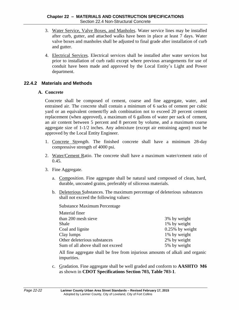
3. Water Service, Valve Boxes, and Manholes. Water service lines may be installed
after curb, gutter, and attached walks have been in place at least 7 days. Water
valve boxes and manholes shall be adjusted to final grade after installation of curb
and gutter.
4. Electrical Services. Electrical services shall be installed after water services but
prior to installation of curb radii except where previous arrangements for use of
conduit have been made and approved by the Local Entity’s Light and Power
department.
22.4.2 Materials and Methods
A. Concrete
Concrete shall be composed of cement, coarse and fine aggregate, water, and
entrained air. The concrete shall contain a minimum of 6 sacks of cement per cubic
yard or an equivalent cement/fly ash combination not to exceed 20 percent cement
replacement (when approved), a maximum of 6 gallons of water per sack of cement,
an air content between 5 percent and 8 percent by volume, and a maximum coarse
aggregate size of 1-1/2 inches. Any admixture (except air entraining agent) must be
approved by the Local Entity Engineer.
1. Concrete Strength. The finished concrete shall have a minimum 28-day
compressive strength of 4000 psi.
2. Water/Cement Ratio. The concrete shall have a maximum water/cement ratio of
0.45.
3. Fine Aggregate.
a. Composition. Fine aggregate shall be natural sand composed of clean, hard,
durable, uncoated grains, preferably of siliceous materials.
b. Deleterious Substances. The maximum percentage of deleterious substances
shall not exceed the following values:
Substance Maximum Percentage
Material finer
than 200 mesh sieve 3% by weight Shale 1% by weight
Coal and lignite 0.25% by weight
Clay lumps 1% by weight
Other deleterious substances 2% by weight
Sum of all above shall not exceed 5% by weight
All fine aggregate shall be free from injurious amounts of alkali and organic
impurities.
c. Gradation. Fine aggregate shall be well graded and conform to AASHTO M6
as shown in CDOT Specifications Section 703, Table 703-1.

Larimer County Urban Area Street Standards – Revised February 17, 2015
Adopted by Larimer County, City of Loveland, City of Fort Collins
Page 22-23
Chapter 22 – MATERIALS AND CONSTRUCTION SPECIFICATIONS Section 22.4 Non-Structural Concrete
4. Coarse Aggregate.
a. Composition. Coarse aggregate shall consist of crushed limestone, trap rock,
granite, washed gravel, or other approved inert materials having clean, hard,
strong, durable pieces, free from adherent coating, and conforming to the
requirements or these specifications.
b. Deleterious Substances. The maximum percentage of deleterious substances
shall not exceed the values listed in Table 22-3.
c. Gradation. Course aggregate shall be well graded and conform to AASHTO
M43 and as shown in CDOT Specifications Section 703, Table 703-1.
5. Fly Ash, Water, Admixtures. Refer to Sections 22.5.5 A.3, 22.5.5 A.5, and 22.5.5
A.6.
B. Job-Mixed Concrete
Job-mixed concrete shall be mixed in a drum-type mixer which shall conform to the
Standards of the Mixer Manufacturers Bureau of the Associated General Contractors
of America.
1. Mixing and Discharging. The mixer shall be capable of combining the aggregates,
cement, and water into a thoroughly mixed and uniform mass within the specified
time and discharge the material without segregation. The entire contents of the
drum shall be discharged before recharging. The volume of the mixed materials
per batch shall not exceed the manufacturer’s rated capacity of the mixer. Mixers
must be kept clean of hardened concrete.
2. Mixing Time and Rate of Revolutions. The mixing of each batch shall continue
for not less than one minute after all materials, except water, are in the drum. All
mixing water shall be introduced before 1/4 of the mixing time has elapsed. The
mixer shall rotate at the rate recommended by the manufacturer, but not less than
14 or more than 20 revolutions per minute. When additional water is added,
another 30 revolutions of the drum will be required.
3. Cement Type. When concrete is mixed at the site, cement must be Type IA or
IIA. The addition of any admixture at the job site is prohibited.
C. Ready-Mixed Concrete
Ready-mixed concrete shall be proportioned, mixed, and transported in accordance
with the current ASTM Specifications for Ready-Mixed Concrete (Designation C-
94). Delivery of central-mixed concrete shall not be made in non-agitating equipment.
22.4.3 Construction
A. Concrete Finishing
1. General.

Page 22-24 Larimer County Urban Area Street Standards – Revised February 17, 2015
Adopted by Larimer County, City of Loveland, City of Fort Collins
Chapter 22 – MATERIALS AND CONSTRUCTION SPECIFICATIONS Section 22.4 Non-Structural Concrete
a. Exposed faces of curbs and sidewalks shall be finished to true line and grade
as shown on the plans. The surface shall be floated to a smooth, but not
slippery finish.
b. After completion of finish and before concrete has taken its initial set, all
edges in contact with the forms shall be edged with an edger.
c. Sprinkling of the surface with water, to facilitate finishing, shall not be
permitted.
2. Finish Types.
a. Broom Finish. All concrete curb-gutter and sidewalk, unless otherwise
specified.
b. Float Finish. All access ramps and transitions shall be hand-finished, with a
wood or magnesium float.
c. Exposed Aggregate for median surface.
3. Markings.
a. Appurtenances. In Ft. Collins (city limits), concrete used in curb-gutter,
sidewalk, curb cuts, driveways, inlets, bicycle paths, retaining walls, and slope
paving shall have the name of the Concrete Contractor and the year of
construction impressed therein, using letters not less than 1 inch high and 3/8
inch deep. Impressions shall be made in concrete at the beginning and end of
each pour.
b. Utility. Impressions (similar to appurtenances) delineating the location of
water and sewer, (S for sanitary sewer, C for clean out, + for water, with the
top of the + pointing to the water stop box), shall be located on the curb face
at all service crossings.
c. Structures. Structures shall have the year constructed impressed therein, using
letters 3 inches high, 1-1/2 inches wide and 3/8 inches deep.
B. Repairs
1. Defective Areas. If, after stripping of forms, any concrete is found to be not
formed as shown on the drawings, or is out of alignment or level, or shows a
defective surface, it shall be considered as not conforming with these Standards.
The defective area shall be removed and replaced by the Developer at his
expense.
2. Sidewalk Areas. For Loveland (GMA and city limits), bolt holes, tie-rod holes,
and minor imperfections, for sidewalks only, as approved by the Local Entity
Engineer, shall be filled with dry-patching mortar.
a. Dry-patching Mortar shall be composed of one part Portland cement to two
parts of regular concrete sand (volume measurement), and water. Use only
enough water that the mortar will stick together upon being molded, after the

Larimer County Urban Area Street Standards – Revised February 17, 2015
Adopted by Larimer County, City of Loveland, City of Fort Collins
Page 22-25
Chapter 22 – MATERIALS AND CONSTRUCTION SPECIFICATIONS Section 22.4 Non-Structural Concrete
ingredients are mixed thoroughly. These mortar mix proportions are
approximate.
b. Placing Mortar. Mortar repairs shall be placed in layers and thoroughly
compacted by suitable tools. Care shall be taken in filling rod and bolt holes
so that the entire depth of the hole is completely filled with compacted mortar.
C. Concrete Curing
1. General. Protect freshly placed concrete from premature drying and excessive
cold or hot temperatures as well as rain, flowing water, and mechanical injury. In
hot, dry, and windy weather, protect concrete from rapid moisture loss before and
during finishing operations with an evaporation-control material.
Start initial curing as soon as free water has disappeared from concrete surface
after placing and finishing.
2. Materials. Refer to the Materials Specification in CDOT 601.13 for concrete
curing methods.
3. Curing Methods. Cure concrete by one of the following methods:
a. Liquid Membrane Curing Compound. Apply pigmented curing compound to
exposed interior slabs and on exterior slabs, walks, and curbs as soon as final
finishing operations are complete. Apply uniformly in continuous operation,
according to manufacturer’s directions, and at a rate of 150 sq ft per gallon for
all concrete. The compound shall be kept agitated to prevent the pigment from
settling.
b. Moisture Retaining Cover Curing. This curing approach is optional in
Loveland (GMA and city limits) only Cover concrete surfaces with moisture-
retaining cover (polyethylene sheets) for curing concrete, placed in widest
practicable width, with sides and ends lapped at least 12 inches and sealed by
waterproof tape or adhesive. Immediately repair any holes or tears during
curing period, using cover material and waterproof tape.
D. Cold Weather Requirements
Refer to 22.3.7 G.
E. Joints
1. Tooled Joints. Transverse joints shall be located at intervals of 10 feet in curbs,
gutters, and crosspans. When combination curb, gutter, and walk are used, the
joint shall be continuous through all three elements with a maximum spacing of
ten feet. The joints shall be initially cut a minimum of one-third the thickness of
the concrete. For detached sidewalks, the tooled joint spacing shall equal the
sidewalk width.
2. Expansion Joints. Expansion joint material shall be installed every 500’ in long
runs and between new structure slabs and existing concrete slabs, where called for
and around fire hydrants, poles, inlets, sidewalk underdrains, midblock ramps,

Page 22-26 Larimer County Urban Area Street Standards – Revised February 17, 2015
Adopted by Larimer County, City of Loveland, City of Fort Collins
Chapter 22 – MATERIALS AND CONSTRUCTION SPECIFICATIONS Section 22.4 Non-Structural Concrete
radius points at intersections, and other fixed objects, i.e. joins with existing
sidewalk slabs and curbs. Expansion joint material must be set vertical and
installed in accordance with the CDOT specification titled M&S Standards for
Concrete Pavement Joints. The joint shall be edged with a suitable edging tool
and sealed in accordance with CDOT Section 412.18.
F. Backfilling
The space adjoining the concrete shall be backfilled with suitable material, properly
compacted, and brought flush with the surface of the concrete and adjoining ground
surface no earlier than 7 days after concrete placement, unless otherwise approved by
the Inspector.
In embankments, the backfill shall be level with the top of the concrete for at least 2
feet and then sloped to meet existing grade. Maximum slope shall be 4:1. For walks
detached from the curb, the space between the curb and walk shall be backfilled on a
straight line from the top of walk to the top of curb.
G. Opening to Traffic
It shall be the Developer’s responsibility to protect new concrete and repairs from
damage with appropriate methods. For areas to be exposed to traffic, the concrete
shall be protected until 80% of required concrete strength is achieved.
H. Warranty
The Developer shall guarantee curb, gutter, walks, driveways, and crosspans after
completion against defective workmanship, materials and vandalism. The
determination of the necessity during such guarantee period for the Developer to
repair said curb, gutters, walks, driveways or crosspans, or any portion thereof, shall
rest entirely with the Local Entity Engineer whose decision upon the matter shall be
final and binding upon the Contractor. Refer to Chapter 24, Acceptance Procedures
and Record Drawings/Warranty, for additional information.
I. Initial and Final Acceptance
Upon substantial completion and upon written request of the Developer, the Local
Entity Engineer shall, with the Developer, physically examine the work and/or phase
of the work. The Local Entity Engineer shall issue written initial acceptance of the
work with a “punch list” of deficiencies to be completed within 30 days and prior to
final acceptance. If no deficiencies are found, the Local Entity Engineer shall issue a
written final acceptance of the work. Refer to Chapter 24, Acceptance Procedures
and Record Drawings/Warranty.
22.4.4 Tunneling or Boring Under Curb, Gutter, Walks, and Pavements
A. General
Excavate surfaces under walks and pavements to indicated cross sections, elevations,
and grades on plans.

Larimer County Urban Area Street Standards – Revised February 17, 2015
Adopted by Larimer County, City of Loveland, City of Fort Collins
Page 22-27
Chapter 22 – MATERIALS AND CONSTRUCTION SPECIFICATIONS Section 22.5 Pavement
B. Borings
Boring for utilities shall be permitted if approved by the Local Entity Engineer.
1. Less Than 6 Inches. For openings less than or equal to 6 inches in diameter, bore
holes shall be filled with patching material (cold mix is not acceptable) to prevent
entry of moisture. Patching material used shall be in all cases compatible with the
existing surface. Subgrade shall be replaced with flowable fill to provide
necessary support to the surface. The sealing of bore holes is the responsibility of
the Contractor or persons making the bore.
2. Greater Than 6 Inches. For openings greater than 6 inches in diameter, the limits
of repair shall be identified in the field.
3. Finished Condition. The completed job shall be flush with the surrounding
pavement and have no indentations, pockets, or recesses that may trap and hold
water.
22.5 PAVEMENT
22.5.1 Fill
Cavities that are a result of excavation and areas deficient in grade shall be brought to
grade with fill material. All imported fill material shall be tested in accordance with
Chapter 23, Street Inspection and Testing Procedures.
A. Engineered Fill
Subbase or base materials. See Sections 22.5.3 and 22.5.4 .
22.5.2 Subgrade and Roadbed
A. General
Subgrade material shall conform to the lines, grades, cross-sections, and thickness
shown on the approved plans and shall be finished and maintained in an acceptable
condition at least one day’s progress in advance of base construction.
B. Subgrade Approval
1. Notification. Notify the Local Entity Engineer when excavations have reached
required subgrade.
2. Inspection. See Chapter 23, Street Inspection and Testing Procedures.
3. Reconstruction. See Chapter 23, Street Inspection and Testing Procedures.
C. Subgrade Preparation
1. Preparation Conditions. Work shall not occur on the subgrade in freezing
conditions, or when the subgrade is frozen.

Page 22-28 Larimer County Urban Area Street Standards – Revised February 17, 2015
Adopted by Larimer County, City of Loveland, City of Fort Collins
Chapter 22 – MATERIALS AND CONSTRUCTION SPECIFICATIONS Section 22.5 Pavement
2. Compaction. The subgrade shall be free of organic material and shall be deep-
plowed to a minimum depth of 12 inches, moisture-treated to within 2 percent (or
as specified on the plans or geotechnical report) of optimum moisture content,
thoroughly mixed, and replaced and compacted to 95% maximum standard
proctor in 6-inch lifts.
3. Testing. See Chapter 23, Table 23-1 Material Testing.
4. Final Proof-Rolling. After the subgrade has been compacted, tested, and found to
meet specifications, the entire subgrade shall be mechanically proof-rolled with a
heavily loaded vehicle to ensure uniformity of the subgrade. The vehicle must
have a loaded GVW of 50,000 pounds with a loaded single axle weight of at least
18,000 pounds and a tire pressure of 90 psi. Subgrade which is pumping or
deforming under loading must be reworked, replaced or otherwise modified, to
form a smooth, stable, non-yielding base for subsequent paving courses. The
Local Entity Engineer shall be notified at least 24 hours before final proof-rolling.
All proof rolls shall be observed and approved by an Inspector.
5. Preparation of Cut Subsurfaces and Undisturbed Areas. Subgrade surfaces below
excavated areas such as cut areas and undisturbed areas require additional
preparation. Unless otherwise approved by the Local Entity Engineer, said
subgrade shall be scarified to a depth of 12-inches, wetted or aerated as needed,
and compacted to 95% maximum standard proctor dry density (AASHTO T-99)
at +/-2% of optimum moisture content for cohesive soils or +/-3% for non-
cohesive soils.
a. Expansive soils, refer to Chapter 10.
6. Acceptance. See Chapter 23, Street Inspection and Testing Procedures.
D. Subgrade Protection
During construction, subgrades and excavations shall be kept shaped and drained.
Ditches and drains along the subgrade shall be maintained to drain effectively at all
times. Where ruts occur in the subgrade, the subgrade shall be brought to grade,
reshaped, and recompacted prior to placing of subbase material. The storage or
stockpiling of materials on the subgrade will not be permitted. No base course shall
be laid until the subgrade has been inspected and approved. Under no circumstances
shall base or pavement material be placed on a muddy or unstable subgrade.
E. Soil Stabilization
1. General. For new construction, soil stabilization shall extend to back of curb for
detached walk and to back of walk for attached walk.
2. Lime Stabilization. This section specifies requirements for design, materials, and
construction of lime-stabilized subgrades. This section is applicable to stabilizing
fine-grained soils (clays and silts) only. It is not applicable to stabilizing sands
and gravels used as bases or subgrades.

Larimer County Urban Area Street Standards – Revised February 17, 2015
Adopted by Larimer County, City of Loveland, City of Fort Collins
Page 22-29
Chapter 22 – MATERIALS AND CONSTRUCTION SPECIFICATIONS Section 22.5 Pavement
a. General. The purpose of lime stabilization is to improve the subgrade quality
of a clay soil by increasing its strength and reducing its swell-shrink potential
during wet-dry cycles.
b. Materials. The material for lime treated subgrade consists of a mixture of
native or imported soils, hydrated or quick lime and water, as outlined by
ASTM Specification C977. Hydrated lime shall conform to the requirements
of ASTM C 207-79, Type N. In addition, the residue retained on a 200 mesh
sieve shall not exceed 10 percent when determined in accordance with ASTM
C 110. Drying of the residue in an atmosphere free from carbon dioxide will
not be required.
The materials to be used in construction shall be tested and a mix design
submitted to the Local Entity Engineer for approval. See Chapter 23, Street
Inspection and Testing Procedures, concerning mix design report.
c. Preparation and Application. The surface of the roadbed shall be graded to the
established lines, grades, and cross sections as shown on the plans. The
prepared roadbed shall be scarified to the depth and width required for the
subgrade stabilization. The material thus obtained shall be pulverized.
Application, mixing, and finishing shall be in accordance with CDOT
Specification Sections 307.05 through 307.09.
d. Design and Testing. A site-specific lime-stabilization design is required prior
to construction and based on a soil report with additional testing required. See
Chapter 5, Soils Investigations and Report. The design shall be prepared by
a Colorado Registered Professional Engineer competent in the field of
geotechnical engineering and shall be included in the Pavement Design Report
as required in Chapter 10, Pavement Design and Technical Criteria.
Testing shall verify that projected “R” values were achieved.
e. Mix Design Approval. To be approved, the mix shall have a minimum 7-day
compressive strength of 160 psi. In addition, the plasticity index of the treated
soil shall not exceed 6. The minimum acceptable hydrated lime content shall
be 4 percent by weight.
Only mix designs approved by the Engineering Division shall be used.
Approvals are required on a project basis prior to issuing construction permits.
Minimum in-place thickness for this material shall be 8 inches.
f. Pavement Design.
1) Flexible Pavement Over Stabilized Subgrade. The AASHTO Guide for
the Design of Pavement Structures is the basis of the Local Entity’s
design procedure. For lime-stabilized subgrades with a minimum
compressive strength of 160 psi, a strength coefficient of 0.14 shall be
used in the layer-thickness equation. Refer to Chapter 10, Pavement
Design and Technical Criteria, for the flexible pavement design
procedure and show calculations in the pavement design report.

Page 22-30 Larimer County Urban Area Street Standards – Revised February 17, 2015
Adopted by Larimer County, City of Loveland, City of Fort Collins
Chapter 22 – MATERIALS AND CONSTRUCTION SPECIFICATIONS Section 22.5 Pavement
2) Rigid Pavement Over Stabilized Subgrade. The appropriate design
nomographs for rigid pavement referenced in Chapter 10, Pavement
Design and Technical Criteria shall be used to determine slab thickness.
Evidence supporting a total modulus of subgrade reaction for the untreated
subgrade and the lime-stabilized layer shall be provided.
3. Fly Ash Stabilization. This item shall consist of treating the subgrade or existing
base, by pulverizing, adding Class C fly ash, and mixing and compacting the
mixed material to the required density. This item applies to natural ground or
embankment and shall be constructed as specified herein and in conformity with
the typical sections, lines and grades as shown on the plans or as established by
the Engineer.
a. Materials.
1) Fly Ash. Fly Ash shall meet ASTM C 618 for Class C Fly Ash.
2) Water. The water used in the stabilization mixture shall be potable.
b. Equipment.
1) The machinery, tools and equipment necessary for proper execution of the
work shall be on the project and approved by the Local Entity Engineer
prior to the beginning of construction operations.
All machinery, tools, and equipment used shall be maintained in a
satisfactory and workmanlike manner.
a) Fly ash shall be furnished in trucks. Each truck shall have the weight
of fly ash recorded on certified scales.
c. Construction Methods.
1) General. It is the purpose of this specification to secure a completed
course of treated material which contains a uniform fly ash/soil mixture
with no loose or segregated areas, has a uniform density and moisture
content, is well bound for its full depth, and has a smooth surface suitable
for placing subsequent courses. It shall be the responsibility of the
Developer to regulate the sequence of work; to process a sufficient
quantity of material to provide full depth as shown on the plans; to use the
proper amounts of fly ash; to maintain the work and to rework the courses
as necessary to meet the above requirements.
2) Preparation of Subgrade. Before other construction operations have begun,
the subgrade shall be graded and shaped to enable the fly ash treatment of
materials in place, in conformance with the lines, grades, and thickness
shown on the plans.
3) Application. The fly ash shall be spread by a method approved by the
Local Entity Engineer at the rates shown on the plans or as directed by the
Local Entity Engineer. Fly ash shall not be applied when wind conditions,

Larimer County Urban Area Street Standards – Revised February 17, 2015
Adopted by Larimer County, City of Loveland, City of Fort Collins
Page 22-31
Chapter 22 – MATERIALS AND CONSTRUCTION SPECIFICATIONS Section 22.5 Pavement
in the opinion of the Local Entity Engineer, are such that blowing fly ash
becomes objectionable to traffic or adjacent property owners.
During final mixing, the materials shall be sprinkled, as directed by the
Local Entity Engineer, until the proper moisture content has been secured.
However, initial mixing after the addition of fly ash will be accomplished
dry, or with a minimum of water, to prevent fly ash balls.
Final moisture content of the mix, prior to compaction, shall not exceed
the optimum moisture content of the mix by more than 2 percent, nor less
than optimum by more than 2 percent. Should the natural moisture content
of the soil be above the specified range, aeration of the soil may be
required prior to addition of the fly ash.
4) Mixing. The soil and fly ash shall be thoroughly mixed by approved road
mixers or other approved equipment. The mixing shall continue until, in
the opinion of the Local Entity Engineer, a homogeneous, friable mixture
of soil and fly ash is obtained, free from all clods or lumps.
Water required to achieve the specified moisture content for the mixture
should be added after initial mixing. There shall be a 6 inch overlap
between passes to assure a consistent mix.
5) Compaction. Compaction of the mixture shall begin immediately after
mixing of the fly ash and shall be completed within two hours following
addition of water to the fly ash. The material shall be sprinkled as
necessary to maintain the optimum moisture.
Compaction of the mixture shall begin at the bottom and shall continue
until the entire depth of mixture is uniformly compacted to the specified
density. All non-uniform (too wet, too dry, or insufficiently treated) areas
that appear shall be corrected immediately by sprinkling and rolling. The
surface of the course shall be maintained in a smooth condition, free from
undulations and ruts, until work is placed thereon of the work is accepted.
The stabilized section shall be compacted to the extent necessary to
provide the density specified in Table 22-1.
Table 22-1 Required Density for Stabilized Compaction
Description Density For fly ash treated subgrade, existing subbase or existing base that will receive subsequent subbase or base courses.
Not less than 95% maximum dry density (ASTM D 698)
For fly ash treated base that will receive surface course.
Not less than 97% maximum dry density (ASTM D 698)

Page 22-32 Larimer County Urban Area Street Standards – Revised February 17, 2015
Adopted by Larimer County, City of Loveland, City of Fort Collins
Chapter 22 – MATERIALS AND CONSTRUCTION SPECIFICATIONS Section 22.5 Pavement
In addition to the requirements specified for density, the full depth of the
material shown on the plans shall be compacted to the extent necessary to
remain firm and stable under construction equipment. After each section is
completed, tests as necessary may be required by the Engineer.
If the material fails to meet the density requirements, the Engineer may
require it to be reworked as necessary to meet those requirements or
require the Developer to change construction methods to obtain required
density on the next section. Throughout this entire operation the shape of
the course shall be maintained by blading, and the surface, upon
completion, shall be smooth and in conformity with the typical section
shown on the plans and to the established lines and grades. Blading should
be terminated within two hours after blending of the fly ash.
Should the material, due to any reason or cause, lose the required stability,
density or finish before the next course is placed, or the work is accepted,
it shall be reprocessed, re-compacted, and refinished at the sole expense of
the Developer. Reprocessing shall follow the same pattern as the initial
stabilization, including the addition of fly ash.
4. Finishing, Curing, and Preparation for Surfacing. After the final layer or course of
the treated subgrade, subbase or base has been compacted, it shall be brought to
the required lines and grades in accordance with the typical sections.
a. The resulting base surface shall be thoroughly rolled with a pneumatic tire
roller and “clipped,” “skinned” or “tight bladed” by a power grader to a depth
of approximately ¼ inch, removing all loosened stabilized material from the
section. Re-compaction of the loose material should not be attempted.
The surface shall then be thoroughly compacted with the pneumatic roller,
adding small increments of moisture as needed during rolling. If plus No. 4
aggregate is present on the surface of the mixture, one complete coverage of
the section with the flat wheel roller shall be made immediately after the
“clipping” operation.
When directed by the Local Entity Engineer, surface finishing methods may
be varied from this procedure provided a dense, uniform surface, free of
surface compaction planes, is produced. The moisture content of the surface
material must be maintained within the specified range during all finishing,
and shall proceed in such a manner as to produce, in not more than two hours,
a smooth, closely knit surface, free of cracks, ridges or loose material
conforming to the crown, grade and line shown on the plans.
1) After the fly ash treated course has been finished as specified herein, the
surface shall be protected against rapid drying in a thorough and
continuously moist condition by sprinkling for a period of not less than
three days, or until the surface or subsequent courses are placed.
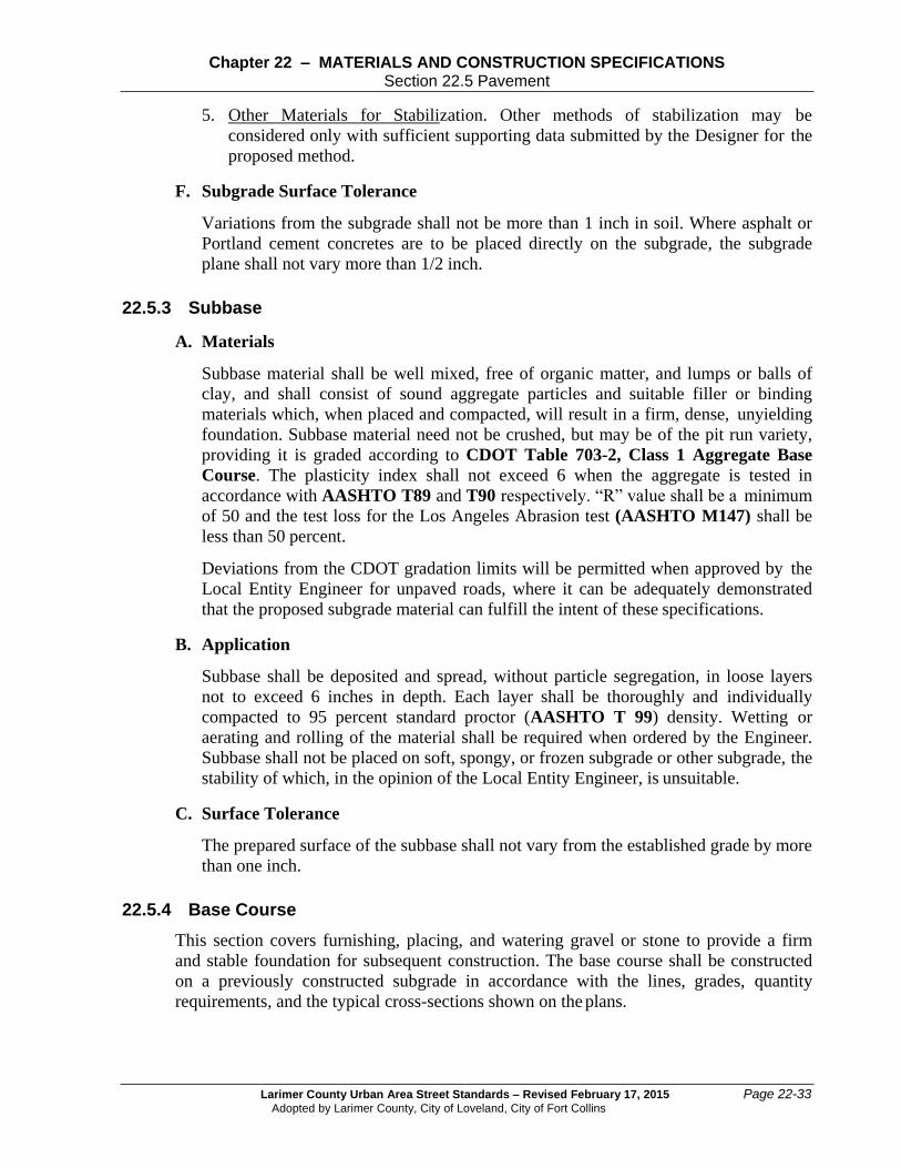
Larimer County Urban Area Street Standards – Revised February 17, 2015
Adopted by Larimer County, City of Loveland, City of Fort Collins
Page 22-33
Chapter 22 – MATERIALS AND CONSTRUCTION SPECIFICATIONS Section 22.5 Pavement
5. Other Materials for Stabilization. Other methods of stabilization may be
considered only with sufficient supporting data submitted by the Designer for the
proposed method.
F. Subgrade Surface Tolerance
Variations from the subgrade shall not be more than 1 inch in soil. Where asphalt or
Portland cement concretes are to be placed directly on the subgrade, the subgrade
plane shall not vary more than 1/2 inch.
22.5.3 Subbase
A. Materials
Subbase material shall be well mixed, free of organic matter, and lumps or balls of
clay, and shall consist of sound aggregate particles and suitable filler or binding
materials which, when placed and compacted, will result in a firm, dense, unyielding
foundation. Subbase material need not be crushed, but may be of the pit run variety,
providing it is graded according to CDOT Table 703-2, Class 1 Aggregate Base
Course. The plasticity index shall not exceed 6 when the aggregate is tested in
accordance with AASHTO T89 and T90 respectively. “R” value shall be a minimum
of 50 and the test loss for the Los Angeles Abrasion test (AASHTO M147) shall be
less than 50 percent.
Deviations from the CDOT gradation limits will be permitted when approved by the
Local Entity Engineer for unpaved roads, where it can be adequately demonstrated
that the proposed subgrade material can fulfill the intent of these specifications.
B. Application
Subbase shall be deposited and spread, without particle segregation, in loose layers
not to exceed 6 inches in depth. Each layer shall be thoroughly and individually
compacted to 95 percent standard proctor (AASHTO T 99) density. Wetting or
aerating and rolling of the material shall be required when ordered by the Engineer.
Subbase shall not be placed on soft, spongy, or frozen subgrade or other subgrade, the
stability of which, in the opinion of the Local Entity Engineer, is unsuitable.
C. Surface Tolerance
The prepared surface of the subbase shall not vary from the established grade by more
than one inch.
22.5.4 Base Course
This section covers furnishing, placing, and watering gravel or stone to provide a firm
and stable foundation for subsequent construction. The base course shall be constructed
on a previously constructed subgrade in accordance with the lines, grades, quantity
requirements, and the typical cross-sections shown on the plans.

Page 22-34 Larimer County Urban Area Street Standards – Revised February 17, 2015
Adopted by Larimer County, City of Loveland, City of Fort Collins
Chapter 22 – MATERIALS AND CONSTRUCTION SPECIFICATIONS Section 22.5 Pavement
A. General
Base material shall conform to the lines, grades, cross-sections, and thicknesses
shown on the approved plans and shall be finished and maintained in an acceptable
condition at least one day’s progress in advance of placing prime coat or paving
material.
B. Aggregate Base Course Material
Base material shall consist of hard, durable particles or fragments of stone or gravel
crushed to the required sizes. Material shall contain an appropriate quantity of sand or
other finely-divided mineral matter which conforms to the requirements of AASHTO
M 147, and to Section 703.03, CDOT Standard Specifications Class 5 or Class 6
Aggregate Base Course. In addition, the material must have an R-value of 72 or
greater, and must be moisture stable. When produced from gravel, not less than 60
percent by weight of the aggregate retained on a No. 4 sieve shall consist of particles
having at least one fractured face. Base material shall be free from vegetable matter
and lumps or balls of clay and when placed and compacted will result in a firm,
dense, unyielding foundation. The Local Entity Engineer may approve recycled
asphalt or concrete pavement.
Coarse aggregate shall show a loss of not more than 50 percent when tested in
accordance with AASHTO Standard Method of Test for Abrasion of Coarse
Aggregate by use of the Los Angeles Machine, Designation: AASHTO T-96
(AASHTO M 147).
1. Approval of Sources. Only aggregate from the Local Entity approved sources
shall be used. Refer to Chapter 23, Street Inspection and Testing Procedures.
(Approval of sources will, at a minimum, consist of supplying documented
gradation, Atterberg limits, and R-value testing on an annual basis).
C. Cement Treated Aggregate Base Course Material
This material shall consist of a mixture of aggregate materials, Portland cement, and
water as outlined in Section 308 of the CDOT Standard Specifications, latest
version. Acceptable aggregates include CDOT Classes 4, 5, and 6. Other aggregates
may be used, if previously approved by the Local Entity Engineer. The materials to
be used in construction shall be tested and a mix design submitted to the Local Entity
Engineer.
1. Mix Design Approval. To be approved, the mix shall have a 7-day compressive
strength of at least 650 psi, and no more than 1000 psi. The minimum acceptable
cement content shall be 5 percent by weight.
Only mix designs approved by the Local Entity Engineer shall be used. Approvals
are required on a project basis, or an annual basis for suppliers, prior to issuing
construction permits.

Larimer County Urban Area Street Standards – Revised February 17, 2015
Adopted by Larimer County, City of Loveland, City of Fort Collins
Page 22-35
Chapter 22 – MATERIALS AND CONSTRUCTION SPECIFICATIONS Section 22.5 Pavement
D. Application
Base material shall be deposited and spread without particle segregation in loose
layers not to exceed 6 inches in depth. Each layer shall be thoroughly and
individually compacted to 95 percent standard Proctor (AASHTO T-99) density.
Wetting or aerating and rolling of the material shall be required as ordered by the
Local Entity Engineer, following review of all field test results. No base course shall
be placed upon a soft, spongy, or frozen subgrade or other subgrade, the stability of
which, in the opinion of the Local Entity Engineer, is unsuitable.
E. Surface Tolerance
The prepared surface of the base shall not vary above or below the established grade
by more than 1/2 inch.
F. Soil Sterilization
Soil sterilization shall be applied under all new paving. The sterilization agent shall
be a pre-emergent herbicide, soluble, dispersible, or mixable in water and nontoxic to
humans when applied per the manufacturer’s recommendations. The agent shall be
active for one year after application. The applicator shall be certified by the U.S.
Environmental Protection Agency and licensed in the State of Colorado as a pesticide
applicator and shall be held responsible for any damage to plant growth outside of the
roadway or to pavement where such damage is attributable to carelessness or
improper application of the agent. Care shall also be taken to prevent contamination
of surface waters.
22.5.5 Portland Cement Concrete Pavement
A. Materials
This material shall consist of a mixture of coarse and fine aggregates, Portland
cement, water, and other materials or admixtures as required. Colorado Department of
Transportation Class “P” or “AX” mix may be used. The only alternatives to “P” or
“AX” shall be according to Section 412.03 of CDOT Standard Specifications.
Other high-early strength concretes may be used only where special conditions
warrant, subject to written approval by the Local Entity Engineer.
1. Portland Cement. Portland cement shall comply with the Colorado Department of
Transportation requirements. The type of cement shall be Type II, unless sulfate
conditions necessitate otherwise. Table 2.2.3 in Chapter 2.2 of ACI 201
indicates recommendations for sulfate resistance.
2. Fine Aggregates. Fine Aggregates shall meet Colorado Department of
Transportation Section 703.01 requirements and gradation as shown in CDOT
Table 703-1 and Table 22-2.
3. Coarse Aggregates. Coarse Aggregates shall meet Colorado Department of
Transportation Section 703.02 requirements and gradation as shown in Table 22-
3.

Page 22-36 Larimer County Urban Area Street Standards – Revised February 17, 2015
Adopted by Larimer County, City of Loveland, City of Fort Collins
Chapter 22 – MATERIALS AND CONSTRUCTION SPECIFICATIONS Section 22.5 Pavement
4. Fly Ash. Fly ash shall comply with Colorado Department of Transportation
Section 701.02.
5. Water. Water shall meet the requirements of Colorado Department of
Transportation Section 712.01.
6. Air Entraining and Chemical Admixtures. Shall meet the requirements of
Colorado Department of Transportation Sections 711.02 and 711.03. No
additive manufactured with the purposeful addition of chloride shall be permitted.
Water-reducing admixtures are used when concrete temperatures are as follows:
Type A is used with ambient temperature range of 50 to 90 degrees inclusive;
Type D is used when ambient temperature is over 90 degrees.
Table 22-2
Fine Aggregates for Portland Cement Concrete
Sieve Size or Test Procedure Percent Passing or Test
Requirement Friable Particles, % 1.0, Maximum Coal & Lignite, % 1.0, Maximum Deleterious Material (AASHTO T-1 1), % 3, Maximum Sand Equivalent (AASHTO T 176), % 80, Minimum Fineness Modulus 2.50–3.50 Sodium Sulfate Soundness, % 20.0, Maximum
Table 22-3 Coarse Aggregates for Portland Cement Concrete
Sieve Size or Test Procedure Percent Passing or Test Requirement
2" 100 1-1/2" 95–100
¾" 35–70 3/8" 10–30 #4 0–5
#200 1.0, Max. (1.5% if crusher fines)
% Wear 45, Maximum Clay Lumps and Friable Particles, % 2.0, Maximum
Coal and Lignite, % 0.5, Maximum Sodium Sulfate Soundness, % 12, Maximum
B. Concrete Forms
Refer to Section 22.3.7 A.4.l. Removal of forms shall occur at no less than 12 hours.
C. Construction
1. Placing. Concrete pavement may be placed using slipform methods or fixed
forms. The concrete shall be deposited on moist subgrade in such a manner as to

Larimer County Urban Area Street Standards – Revised February 17, 2015
Adopted by Larimer County, City of Loveland, City of Fort Collins
Page 22-37
Chapter 22 – MATERIALS AND CONSTRUCTION SPECIFICATIONS Section 22.5 Pavement
require as little rehandling as possible. Reasonable care shall be taken to prevent
any segregation of the concrete materials. Workers shall not be allowed to walk in
freshly mixed concrete with boots or shoes coated with earth or foreign
substances.
2. Vibrating. Concrete shall be thoroughly consolidated against and along the faces
of all forms and along the full length and on both sides of all joint assemblies by
means of vibrators inserted in the concrete. Vibrators shall not be permitted to
come in contact with a joint assembly, the grade, or a side form. Vibrators shall
not be used to move the concrete into place.
3. Consolidation and Floating. The concrete shall be struck off and consolidated
with a mechanical finishing machine, vibrating screed, or hand finishing methods.
A slipform paver may also be used. After the concrete has been struck off and
consolidated and joints formed (if necessary), it shall be leveled with a bull float
having a handle to permit operation from the edge of the pavement. Any excess
water and latencies shall be removed from the surface of the pavement. The
straightedge shall be operated at 90 degrees to the transverse joints and shall be
overlapped 1/2 of its length after each pass. Irregularities shall be corrected by
adding or removing concrete. All disturbed places shall again be straight-edged.
The use of hand tools shall be kept to a minimum. They may be used in areas not
accessible to finishing equipment and for compacting concrete in the vicinity of
formed joints.
4. Joints. Transverse and longitudinal joints shall be constructed to the dimensions
and at the spacing shown on the plans. Transverse joints shall extend the entire
width of the pavement and through the curbs. Joints may be formed in the plastic
concrete or sawed after the concrete has hardened. Tooled joints may be
constructed by depressing an approved tool into the plastic concrete cut a
minimum of 1/3 the thickness of the slab.
Sawing of joints shall begin as soon as the concrete has hardened sufficiently to
permit sawing without excessive raveling and before uncontrolled cracking
occurs. If necessary, the sawing operations shall be carried on both day and night,
regardless of weather conditions. At Contractor’s option, tooled joints may be
installed during initial placement to control cracking.
a. Construction Joints. All longitudinal joints may be construction joints at the
Contractor’s option. Transverse construction joints shall be installed whenever
the placing of concrete is suspended an excessive length of time as determined
by the Local Entity Engineer.
b. Joint Filling. Joints shall be filled in accordance with CDOT 412.18 before the
pavement is opened to traffic. Prior to filling, all foreign material shall be
removed from the joints and the joints shall be thoroughly dry. Where
preformed compression-type sealers are used, they shall be lubricated to allow
the sealer to be inserted the full depth of the joint. Liquid elastic type fillers
shall be poured to within 1/4 inch of the top of the joint. Care should be taken
to keep from over-filling the joint.

Page 22-38 Larimer County Urban Area Street Standards – Revised February 17, 2015
Adopted by Larimer County, City of Loveland, City of Fort Collins
Chapter 22 – MATERIALS AND CONSTRUCTION SPECIFICATIONS Section 22.5 Pavement
5. Curing. Refer to the Materials Specification in CDOT 601.13 for concrete curing
methods.
6. Opening to Traffic. The Local Entity Engineer shall decide when the pavement shall be opened to traffic. It shall not be opened to traffic until the field-cured
concrete has attained a flexural strength of 450 psi, and a compressive strength of 3,000 psi or .80 Fc’, whichever is greater. If such tests are not conducted, the
pavement shall not be opened to traffic until 14 days after the concrete is placed. Before opening to traffic, the pavement shall be cleaned.
D. Warranty
Refer to Section 22.4.3 H and substitute the word “street” for the words “curb,
gutters, walks, driveways and crosspans.”
E. Initial and Final Acceptance
Refer to Section 22.4.3 I.
22.5.6 Asphalt Pavement
This section specifies materials and methods to be used for constructing superior
performing pavements for streets, or other miscellaneous areas within the Right-of-Way.
This work shall consist of constructing one or more courses of plant mix hot asphalt
pavement, overlay, or leveling course on a prepared foundation and to the finished
dimensions shown on the plans, or as directed by the Local Entity Engineer. (Reference
CDOT 403)
A. Materials
1. Aggregates. All Aggregates shall conform to the current Colorado Department of
Transportation “Standard Specifications for Road and Bridge Construction”.

Larimer County Urban Area Street Standards – Revised February 17, 2015
Adopted by Larimer County, City of Loveland, City of Fort Collins
Page 22-39
Chapter 22 – MATERIALS AND CONSTRUCTION SPECIFICATIONS Section 22.5 Pavement
Table 22-4 Design Mix Criteria
Property
Test
Method
Value for All Gradings
(gyrations)
(75) (100)
Reference
Air Voids, percent at: N (design) CPL 5115 3.5 – 4.5 3.5 – 4.5
Lab Compaction (gyrations): N (design)
CPL 5115 75 100
Hveem Stability, minimum CPL 5106 28 30 Aggregate Retained on the 4.75mm (No. 4) sieve with at least 2 mechanically induced fractured faces, % minimum
CP 45
90
90
Accelerated Moisture Susceptibility Tensile Strength Ratio (Lottman), minimum
CPL 5109; Method B
80
80
Minimum Dry Split Tensile Strength, psi
CPL 5109; Method B 30 30
Grade of Asphalt Binder, Top Layer
See Table 22-7
Grade of Asphalt Binder, below Top Layer
See Table 22-7
Voids in Mineral Aggregate (VMA), % minimum CP 48 See Table 22-6
Voids Filled with Asphalt (VFA), % AI SP-2 65 - 80 65 - 75
Aggregate Design Grading CDOT S or SX S or SX Laboratory Design Temperatures See Table 22-5 Note: 1. AI SP-2 = Asphalt Institute Superpave Series No. 2 2. The current version of CP (Colorado Department of Transportation) standards is available from the Region 4
Materials Engineer. 3. Warm mix asphalt is allowed as an alternate to Hot Mix Asphalt, provided all material requirements and
specifications are met and approved by the Local Entity Engineer. The supplier and method of warm mix asphalt must be on CDOT approve list.
4. Gyration design revolution (Ndes) will be 75 unless otherwise specified by the Local Entity Engineer based upon project specific criteria and/or traffic levels.

Page 22-40 Larimer County Urban Area Street Standards – Revised February 17, 2015
Adopted by Larimer County, City of Loveland, City of Fort Collins
Chapter 22 – MATERIALS AND CONSTRUCTION SPECIFICATIONS Section 22.5 Pavement
Table 22-5 Laboratory Mix Design Temperatures
Superpave Binder Grade
Laboratory Mixing
Temperature, oC (
oF)
Laboratory Compaction
Temperature, oC (
oF)
PG 58 - 28 154 (310) 138 (280) PG 64 - 22 163 (325) 149 (300) PG 64 - 28 163 (325) 149 (300)
Warm Mix Asphalt is exempt from this table
*All temperatures in this table have a tolerance of + 2.8oC (+ 5
oF)
Table 22-6 Minimum Voids in the Mineral Aggregate (VMA)
Nominal Maximum Size
1, mm (inches)
Design Air Voids2
3.5% 4.0% 4.5%
37.5 (1-1/2) 11.5 12.0 12.5 25.0 (1) 12.5 13.0 13.5
19.0 (3/4) 13.5 14.0 14.5 12.5 (12.5) 14.5 15.0 15.5
9.5 (3/8) 15.5 16.0 16.5 Notes:
1. The Nominal Maximum Size is defined as one sieve larger than the first sieve to retain more than 10%. 2. Interpolate specified VMA values for design air voids between those listed. 3. Air Void Criteria: A design air void range of 3.5 to 4.5% with a target of 4.0% will be used on all mixes. The air void criteria will be applied to the approval of the design mix.
Selection of Gyratory Design Revolutions. Gyratory Design Revolutions shall be
as follows: for arterial roadways 100 gyrations; for collector and local roadways
75 gyrations.
2. Selection of Performance Graded Binders (Asphalt Cement) for Mix Design
a. Asphalt Binders Permitted
The Asphalt binder properties address pavement performance for the climate and
traffic found in the specific area of the project. The high and low temperature
properties required are then specified according to a percent reliability against
rutting (high temperature properties) and thermal cracking (low temperature
properties) found for a given pavement. The high and low temperatures used to
select asphalt cement grades are pavement temperatures at 20 mm below the
pavement surface and at the pavement surface respectively.
The physical properties that the asphalt cement are required to meet stay the same.
What changes is the temperature at which these asphalt cement properties must be
met.

Larimer County Urban Area Street Standards – Revised February 17, 2015
Adopted by Larimer County, City of Loveland, City of Fort Collins
Page 22-41
Chapter 22 – MATERIALS AND CONSTRUCTION SPECIFICATIONS Section 22.5 Pavement
Because of the many climate conditions, specifying asphalt cements based on
climate conditions results in a very large number of asphalt cements nationwide.
However, only a limited number of PG grades are needed for Colorado.
Therefore, only three PG Graded Binders will generally be permitted in these
specifications. PG 58-28, PG 64-22, PG 64-28
Asphalt Binders shall conform to the requirements listed in the current Colorado
Department of Transportation Standard Specifications for Road and Bridge
Construction.
b. Binder Grades
In an effort to simplify the binder selection process, the following binder grades
have been specified for the various types of construction and road classifications.
Refer to Table 227.
Table 22-7 Binder Grade Requirement
Top Lift Lower Lift
Local/Residential PG 58-28 Local/Residential PG 58-28
Minor Collector PG 58-28 Minor Collector PG 58-28 Major Collector PG 64-28 Major Collector PG 64-22 Industrial/Commercial PG 64-28 Industrial/Commercial PG 64-22 Arterial PG 64-28 Arterial PG 64-22
3. Anti-Stripping Additive. An anti-stripping additive shall be required and the
following shall apply:
a. Hydrated Lime. If additive is not added at refinery, a minimum of one percent
hydrated lime by mass (weight) of the combined aggregate shall be added to
the aggregate for all hot asphalt pavement. Hydrated lime shall meet the
requirements of ASTM C207, Type N. The “F” factor used in calculating P
values for lime gradation shall be 0.3.
b. Liquid Additive
1) The Developer shall use an approved anti-stripping additive. The amount
of additive used shall be a minimum of 0.5 percent by mass (weight) of
the asphalt cement.
2) In-Line Blender. The additive shall be added at the refinery or at the hot
plant. If liquid anti-stripping additive is added at the plant, an approved in-
line blender must be used. The blender shall be in the line from the storage
tank to the drier drum or pugmill. The blender shall apply sufficient
mixing action to thoroughly bmix the asphalt cement and anti-stripping
additive.

Page 22-42 Larimer County Urban Area Street Standards – Revised February 17, 2015
Adopted by Larimer County, City of Loveland, City of Fort Collins
Chapter 22 – MATERIALS AND CONSTRUCTION SPECIFICATIONS Section 22.5 Pavement
4. Filler. Filler shall meet the requirements of AASHTO M17.
B. Job Mix
1. Testing Laboratory. See Chapter 23, Job Mix for Asphalt Asphaltic Concrete
Pavement.
2. Composition of Mixtures. The Asphalt plant mix shall be composed of a mixture
of aggregate, filler or additives if required and approved, asphalt material, and
reclaimed material if permitted and used.
3. Mix Design. The Contractor shall submit the following to the Engineer for each
proposed mix design:
a. A proposed mix design job-mix gradation for each mixture certified by an
AASHTO accredited laboratory complying with CDOT Field Materials
Manual Colorado Procedure 10 shall be wholly within the Master Range
Table, Table 22-8. The mass of lime shall be included in the total mass of the
material passing the No. 200 sieve. The restricted zone boundaries given in
the Asphalt Institute’s Superpave Series No. 2 (SP-2) Manual, Appendix B,
are to be used as guidelines in mix design development. However, the job-mix
gradation is not required to pass above or below the restricted zone
boundaries.
b. The aggregate source, percentage of each element used in producing the final
mix, the gradation of each element, and the proposed job-mix formula (JMF)
gradation. The gradation used shall be based on the Contractor’s JMF.
c. The name of the asphalt cement supplier.
4. Sampling for JMF Testing. The contractor’s proposed job-mix formula for each
hot asphalt pavement grading will be tested utilizing materials actual produced
and stockpiled.
5. JMF Target Values. The job-mix formula for each mixture shall establish a single
percentage of aggregate passing each required sieve size, a single percentage of
asphalt material to be added to the aggregate, and a single temperature for the
mixture at the discharge point of the plant.
6. Aggregate Source Changes. Should a change in the sources of material be made,
a new job-mix formula shall be established and approved in accordance with
section 3 before the new material is used.
7. Recycle Asphalt Pavement. The hot asphalt pavement shall not contain more than
20 percent reclaimed asphalt pavement where allowed. The reclaimed asphalt
pavement shall meet the requirements of CDOT subsection 703.04.
8. Aggregate Quality. Test for cleanliness, abrasion loss, and percent of fractured
faces will be made on representative samples of aggregate taken during
production or from the stockpiles.

Larimer County Urban Area Street Standards – Revised February 17, 2015
Adopted by Larimer County, City of Loveland, City of Fort Collins
Page 22-43
Chapter 22 – MATERIALS AND CONSTRUCTION SPECIFICATIONS Section 22.5 Pavement
9. JMF Compliance. When laboratory tests indicate that a proposed job-mix
formula complies with the specifications the JMF may be submitted for mix
design approval in accordance with section 3.
10. Mix Design Approval. Mix designs will be approved on a Laboratory/Production
approval system. Initial approval will be given based on laboratory design.
Production approval will then be given based on testing conducted on plant mixed
samples to verify the approved laboratory design.
New mix design shall be submitted for approval for a two year period with a one
point verification submitted and approved on an annual basis. Should a change in
sources of materials be made a new mix design will be required & shall remain in
effect for the remainder of the approval period.
a. Laboratory Mix Design Approval. The Developer may receive preliminary
mix design approval of a new asphalt mix design, based on the following
procedure:
1) The mix designs will be performed by an AASHTO accredited laboratory
complying with CDOT Field Materials Manual Colorado Procedure 10
and approved by the Local Entity.
2) Conditions. The following conditions shall apply to this preliminary
approval:
a) Written Request and Submittals. The Developer shall make a written
request for preliminary mix design approval, and submit three copies
of the independent lab mix design containing all the information
required in Laboratory Mix Design checklist in Appendix E-7.
b) Test Results. The results of all required tests shall meet the mix design
specification requirements listed in Table 23.5.
c) Asphalt Content. The Local Entity Engineer, only, shall approve the
asphalt content based on the private lab mix design.
b. Production Mix Design Approval. The Developer may receive and maintain
production mix design approval of an HMA mix design, based on the
following procedure:
1) Following laboratory mix design approval verification of mix properties
will be performed by an independent laboratory on plant-produced mix
and approved by the Local Entity. This verification is to be performed on
or before the first day of production within the GMA.
2) To maintain production mix design approval verification of mix properties
shall be performed by an independent laboratory on plant-produced mix
and approved by the Local Entity every 10,000 ton of mix produced.
3) Conditions. The following conditions shall apply to production mix
design approval:

Page 22-44 Larimer County Urban Area Street Standards – Revised February 17, 2015
Adopted by Larimer County, City of Loveland, City of Fort Collins
Chapter 22 – MATERIALS AND CONSTRUCTION SPECIFICATIONS Section 22.5 Pavement
a) Written Request and Submittals. The Developer shall make a written
request for production mix design approval, and submit the results of
the mix verification report performed by a independent lab.
b) Test Results. The results of all required tests shall meet the mix design
specification within the tolerances listed in Error! Reference source
not found.8.
Table 22-8 Tolerances for Hot Mix Asphalt
Element Tolerance Asphalt cement content +/-0.30% Voids in Mineral Aggregate (VMA) +/-1.2% Air Voids (Va) +/-1.2% Lottman Min. 80 Hot Mix Asphalt Gradation Passing the 3/8” and larger sieves +/-6% Passing the No. 4 and No. 8 sieves +/-5% Passing the No. 30 sieve +/-4% Passing the No. 200 sieve +/-2%
c) Local entity shall have 5 days to review production mix design
verification test results and approve or reject the mix design.
d) Stop Work. If the results of mix design verifications are not within the
tolerances as determined by the local entity the contractor shall
immediately stop paving within the GMA and submit a mitigation plan
to the local agency for approval. If given approval paving may resume
and a new mix design verification test will be performed on the first
day of production. If after implementation of the mitigation plan the
contractor in not capable of meeting the original mix design
specifications he shall complete and submit a new mix design to the
local entity for laboratory mix design approval.
22.5.7 Construction Requirements
1. Weather.
a. Placement Temperatures. Plant mix pavement shall be placed only on
properly prepared unfrozen surfaces which are free of water, snow, and ice.
The plant mix pavement shall be placed only when both the air and surface
temperatures equal or exceed the temperatures specified in Error! Reference
source not found.9 and the Local Entity Engineer determines that the weather
conditions permit the pavement to be properly placed and compacted.

Larimer County Urban Area Street Standards – Revised February 17, 2015
Adopted by Larimer County, City of Loveland, City of Fort Collins
Page 22-45
Chapter 22 – MATERIALS AND CONSTRUCTION SPECIFICATIONS Section 22.6 Miscellaneous
Table 22-9 Placement Temperature Limitations in °F
Compacted Layer Thickness in Mm (Inches)
Minimum Surface and Air Temperature ° F
Top Layer
Layers Below Top Layer
2” – 3” 3 or more
50 45
40 35
Note: Air temperature is taken in the shade. Surface is defined as the existing base on which the new pavement is to be placed. If the temperature falls below the minimum air or surface temperatures, paving shall stop.
b. Temporary Pavement Layer. The Work shall be scheduled so that no planed
or recycled surface is left without resurfacing for more than 10 calendar days
from October 1 to March 1. The Developer shall immediately place a
temporary hot asphalt pavement layer on any surface that has been planed or
recycled and cannot be resurfaced in accordance with the above temperature
requirements within 10 calendar days after being planed or recycled.
1) Thickness. The minimum thickness of the temporary hot asphalt pavement
layer shall be 2 inches. The Developer shall perform the quality control
required to assure adequate quality of the hot asphalt pavement used in the
temporary layer.
2) Markings. All applicable pavement markings shall be applied to the
temporary layer surface.
3) Maintenance. The Developer shall maintain the temporary layer for the
entire period that it is open to traffic. Distress that affects the ride, safety,
or serviceability of the temporary layer shall be immediately corrected to
the satisfaction of the Local Entity Engineer.
4) Removal. The temporary hot asphalt pavement layer shall be removed
when work resumes.
22.6 MISCELLANEOUS
22.6.1 Rebuilt Miscellaneous Structures
A. General
This section addresses removing, relaying, resetting, or adjusting structures, fences,
guard rail, signs, pipe, end sections, traffic signals, and related materials. All
designated items shall be carefully removed and every precaution taken to avoid
damage. Coordinate relocation of permanent traffic devices with the Local Entity
Engineer. The Developer will be required to replace or repair any material damaged

Page 22-46 Larimer County Urban Area Street Standards – Revised February 17, 2015
Adopted by Larimer County, City of Loveland, City of Fort Collins
Chapter 22 – MATERIALS AND CONSTRUCTION SPECIFICATIONS Section 22.6 Miscellaneous
due to their operations at their own expense. The work shall include the back-filling
of any resulting trenches, holes, or pits.
B. Construction
1. Pipe to be re-laid and structures to be re-set shall be thoroughly cleaned. Removal
sites shall be neatly backfilled with suitable material and compacted in
accordance with these Standards.
2. All material that is unserviceable shall be handled according to CDOT
Specifications Section 210.02.
3. Fences and gates should be rebuilt or reset according to CDOT Specifications
Section 210.04.
4. Mailboxes complete with supporting structures are to be removed and reset
according to CDOT Specification Section 210.06. Reset height shall be 42 to 48
inches. The box face shall be no closer than 2 feet from the curb face or edge of
sidewalk, whichever is applicable.
5. Re-setting of all traffic control signs and traffic signaling devices will conform to
Section 22.6.2 and be coordinated with the Local Entity Engineer.
6. Structures shall be adjusted according to CDOT Specifications Section 210.10.
7. At no time shall manholes and valve boxes be covered up or buried. Valve boxes
and manholes are to be maintained fully accessible at all times for emergency and
maintenance operation by the Local Entity personnel.
22.6.2 Traffic Signals, Signing, and Striping
A. General
This section addresses the material specifications for traffic control devices as well as
requirements for their installation.
The specification and installation of all traffic control devices shall conform to the
Manual on Uniform Traffic Control Devices and the Colorado Standard
Specifications for Road and Bridge Construction, latest edition.
Permanent signing, striping, and traffic signals, shall be in place before new roadways
are completely opened to the public.
1. Traffic Control Devices on Public Property. The Developer shall submit a striping
and signage plan approved by the Local Entity Engineer. The Developer shall
install all traffic control devices, except signals. Devices shall be placed to
conform to the drawing details.
2. Traffic Control Devices on Private Property.
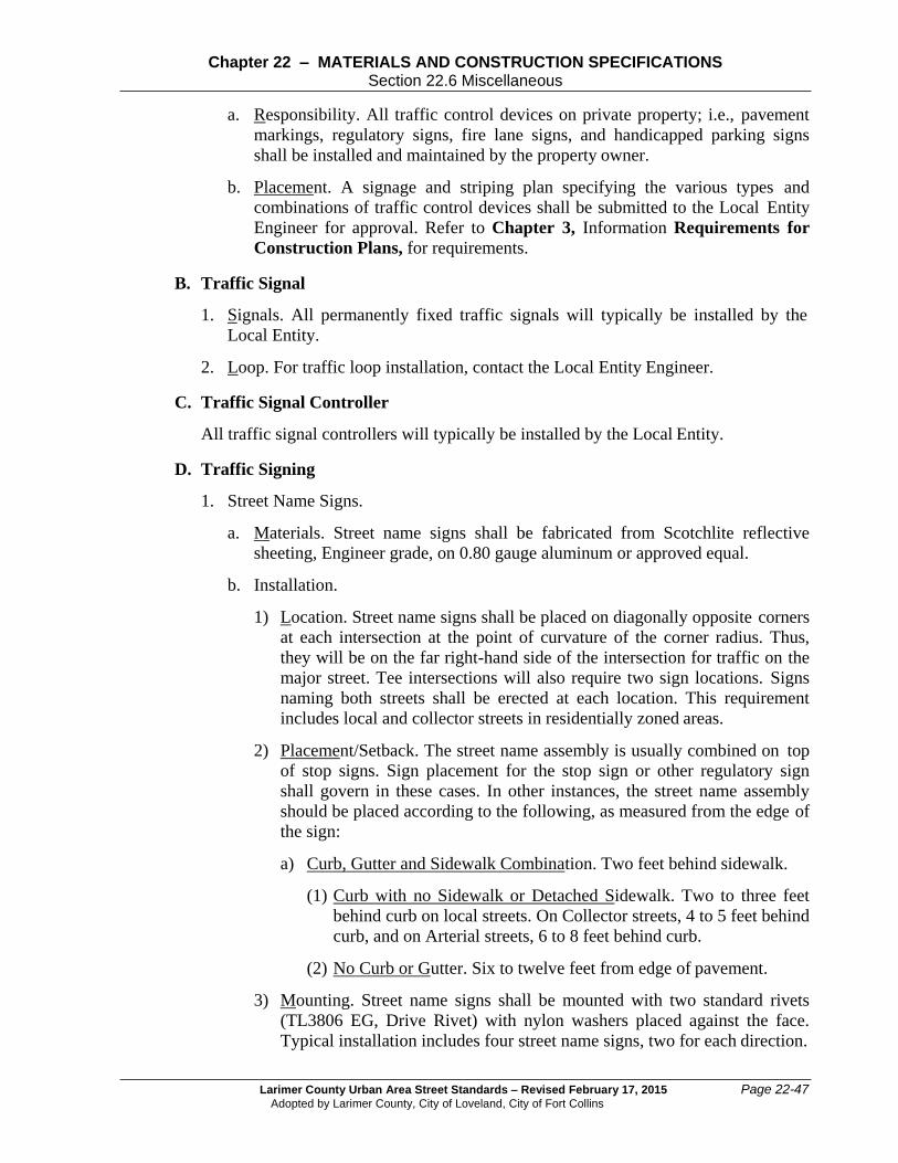
Larimer County Urban Area Street Standards – Revised February 17, 2015
Adopted by Larimer County, City of Loveland, City of Fort Collins
Page 22-47
Chapter 22 – MATERIALS AND CONSTRUCTION SPECIFICATIONS Section 22.6 Miscellaneous
a. Responsibility. All traffic control devices on private property; i.e., pavement
markings, regulatory signs, fire lane signs, and handicapped parking signs
shall be installed and maintained by the property owner.
b. Placement. A signage and striping plan specifying the various types and
combinations of traffic control devices shall be submitted to the Local Entity
Engineer for approval. Refer to Chapter 3, Information Requirements for
Construction Plans, for requirements.
B. Traffic Signal
1. Signals. All permanently fixed traffic signals will typically be installed by the
Local Entity.
2. Loop. For traffic loop installation, contact the Local Entity Engineer.
C. Traffic Signal Controller
All traffic signal controllers will typically be installed by the Local Entity.
D. Traffic Signing
1. Street Name Signs.
a. Materials. Street name signs shall be fabricated from Scotchlite reflective
sheeting, Engineer grade, on 0.80 gauge aluminum or approved equal.
b. Installation.
1) Location. Street name signs shall be placed on diagonally opposite corners
at each intersection at the point of curvature of the corner radius. Thus,
they will be on the far right-hand side of the intersection for traffic on the
major street. Tee intersections will also require two sign locations. Signs
naming both streets shall be erected at each location. This requirement
includes local and collector streets in residentially zoned areas.
2) Placement/Setback. The street name assembly is usually combined on top
of stop signs. Sign placement for the stop sign or other regulatory sign
shall govern in these cases. In other instances, the street name assembly
should be placed according to the following, as measured from the edge of
the sign:
a) Curb, Gutter and Sidewalk Combination. Two feet behind sidewalk.
(1) Curb with no Sidewalk or Detached Sidewalk. Two to three feet
behind curb on local streets. On Collector streets, 4 to 5 feet behind
curb, and on Arterial streets, 6 to 8 feet behind curb.
(2) No Curb or Gutter. Six to twelve feet from edge of pavement.
3) Mounting. Street name signs shall be mounted with two standard rivets
(TL3806 EG, Drive Rivet) with nylon washers placed against the face.
Typical installation includes four street name signs, two for each direction.

Page 22-48 Larimer County Urban Area Street Standards – Revised February 17, 2015
Adopted by Larimer County, City of Loveland, City of Fort Collins
Chapter 22 – MATERIALS AND CONSTRUCTION SPECIFICATIONS Section 22.6 Miscellaneous
4) Post and Mounting Installation. Refer to Sections 22.6.2 D.6.a and 6.b.
2. Traffic Control Signs. Traffic control signs are categorized as regulatory,
warning, and guide signs.
a. Materials. All regulatory signs shall be fabricated using reflective Diamond
grade sheeting, on aluminum blanks.
b. Installation. These signs shall be placed generally as per the MUTCD and the
Colorado Supplement.
c. Mounting. Traffic control signs shall be mounted on existing sign posts, street
lights, and utility poles where possible. Refer to Section 22.6.2 D.6.
3. Crosswalk Signs.
a. Materials, Installation, and Mounting. Materials for and installation and
mounting of signs for crosswalks shall be in accordance with the above
Section 22.6.2 D.2. All pedestrian crossing and W16-7P signs shall use
fluorescent yellow/green (diamond grade) sheeting.
b. Placement. A crosswalk sign with the W16-7P “Arrow” placard shall be
erected at the crosswalk and at a minimum distance before the crosswalk
without placard per M.U.T.C.D. requirements.
4. Roundabout Signs.
a. Materials, Installation and Mounting. Materials for and installation and
mounting of signs for Roundabouts shall be in accordance with the above
Section 22.6.2 D.2.
b. Placement. The in advance warning and regulatory signs (refer to Chapter 14,
Traffic Control Devices) and “Yield” sign shall be placed in accordance with
MUTCD. The “Arrow” signs shall be placed two feet outside the edge of the
circulating roadway per MUTCD between each entrance and exit of the
roundabout. Refer to Figure 8-14 for general locations.
5. Bikeway Signs. “No Parking” signs (R7-9a) as shown in Construction Drawing
1402 shall be installed, generally, at intervals of 250 feet, at an angle of 45
degrees to the roadway.
6. Posts and Mountings.
a. Materials. The sign post system shall be comprised of three sections, an
anchor, post, and sign. The anchor specification shall be Telspar 22F12A-
03PG-2-1/4 inch square x 3 feet, 12 gauge, Anchor Stub with holes. The post
specification shall be Telspar 20F12P-10PG – 2 inch square x 10 feet, 12
gauge, post with holes. Refer to Section 22.6.2 D.2 for sign materials.
b. Installation. The anchor is driven into the ground 30 to 33 inches with 6 to 3
inches above the adjacent ground level. The square post section with holes is
inserted into the anchor six to eight inches and bolted with two 2-1/2 inch

Larimer County Urban Area Street Standards – Revised February 17, 2015
Adopted by Larimer County, City of Loveland, City of Fort Collins
Page 22-49
Chapter 22 – MATERIALS AND CONSTRUCTION SPECIFICATIONS Section 22.6 Miscellaneous
long, 3/8 inch hex head bolts. These bolts are installed at the top two holes at
90 degrees to one another.
c. Mounting. The top of the sign shall be mounted with one TL3806 EG Drive
Rivet with a nylon washer on the sign face. The bottom of the sign shall be
mounted using one 5/16” hex bolt, one metal washer, and one nylon washer
against the sign face. A 5/16” hex nut is used to secure the bolt on the
backside of the post.
7. Sign Height. Signs shall be mounted at a height of 7 feet, measured from the
bottom of the sign to the top of curb. The height to the bottom of a secondary sign
mounted below another sign shall be 6 feet from the top of the curb. Where a
traffic control sign is mounted on the same post with a street name sign, it shall be
placed below the street name sign, with the bottom of the traffic control sign 7
feet from the top of curb.
E. Traffic Striping and Marking
1. General. Existing and temporary pavement striping and marking shall be removed
prior to new installations according CDOT Specifications Section 202.05.
Surfaces shall be thoroughly cleaned and prepared prior to application of striping
and marking.
On chip seals, changes to existing markings shall require removal of existing
markings prior to new installations. Removal shall be according to CDOT
Specifications Section 202.05 which could include water blasting, sandblasting, or
grinding.
A Right-of-Way Work Permit is required prior to striping removals and
installations. Refer to Chapter 6, Permits, for permits.
2. Striping.
a. Striping Materials.
1) Asphalt Pavement. All new striping on asphalt streets shall meet the
minimum standards for latex applications. A minimum of 15 mils thick
(when dry) of latex paint (Flint Trading Co.) specified in CDOT
Specifications Section 708.05 will be used. The paint will be used with
standard moisture resistant beads specified in CDOT Specifications
Section 713.08 and designed for waterborne paint. The beads shall be
applied at a minimum rate of 6.5 pounds per gallon of paint applied.
2) Concrete Pavement. Striping on concrete streets shall meet the minimum
standards for latex waterborne paint per CDOT Specifications Section
708.05.
b. Pre-Striping Materials. Layout (spot taping) of striping shall be done using
standard, reflective 3M Temporary (foil backed) roadway marking tape
specified according to CDOT Specifications Sections 713.14 and 713.15 or
tabs (for chip seals or slurry seals only). Tape shall be 4 x 4 inches. Tabs and
tape shall be the same color as the future striping and symbols.

Page 22-50 Larimer County Urban Area Street Standards – Revised February 17, 2015
Adopted by Larimer County, City of Loveland, City of Fort Collins
Chapter 22 – MATERIALS AND CONSTRUCTION SPECIFICATIONS Section 22.6 Miscellaneous
c. Pre-striping. Prior to permanent installation of traffic striping, the contractor
shall place temporary tabs or tape depicting alignment and placement of the
same. Prior to the use of tape or tabs, a layout shall be done neatly using string
or chalk line, inspected, and adjusted as necessary and must be in the center of
the line.
d. Layout and Tab Installation. Installation of temporary marking tape shall be
according to CDOT Specifications Section 627.08. There shall be a tab or
tape for each line. Therefore, in the case of a double line, there will be two
tabs, one for each line. To improve night visibility, protective tab covers shall
be removed immediately after chip, slurry, or sand sealing.
A typical 25-foot spacing of tabs or temporary tape for each spot will be used.
Breaks in each line shall be marked with a “T” (using tape) to define the end
and beginning of lines.
e. Striping Application. Application rates and specifications for striping shall be
according to CDOT Specifications Section 627.04. Striping on new asphalt
and/or concrete pavement must receive two (2) full applications (two coats) of
paint with beads. Refer to Construction Drawings 1403 and 1404.
1) Centerline. All centerline striping shall be double yellow, each 4 inch
wide, with a 4-inch minimum gap between the two.
2) Parking Stalls and Angle Parking. All striping for parking conditions shall
be white and 4 inches wide. All edge lines of parking areas shall also be
white and a minimum of 4 inches wide.
3) Turn Bays. If a turn bay occurs on a curve, it shall be marked with an 8-
inch wide dotted extension line, in accordance with MUTCD
requirements.
3. Marking.
a. Materials. All pavement markings such as arrows, onlys, crosswalks, stopbars,
and bike symbols shall meet minimum standards for preformed thermoplastic.
Refer to Chapter 14, Traffic Control Devices, for specifications. A
minimum thickness of 125 mil (Flint Trading Co.) or approved equal, shall be
required. Markings on all concrete (and where required by manufacturer on
asphalt) shall use correct 2 part primer. Other requirements from CDOT
Specifications Section 708.07 still apply.
b. Application. Application specifications shall be according to CDOT
Specifications Sections 627.06 and 627.07.
c. Stopbars. Stopbars are to be installed in accordance with the Local Entity
Engineer. Refer to Construction Drawing 1403.
d. Crosswalks. Crosswalks will be marked using the continental/Denver style
starting from the flowline (or extended flowline) then back from the
intersection the standard 9 feet in Loveland (GMA and city limits),, or 12 feet
in Fort Collins (GMA and city limits). Where a concrete pan is present the
concrete surface cure shall be removed, the

Larimer County Urban Area Street Standards – Revised February 17, 2015
Adopted by Larimer County, City of Loveland, City of Fort Collins
Page 22-51
Chapter 22 – MATERIALS AND CONSTRUCTION SPECIFICATIONS Section 22.6 Miscellaneous
specific manufacturer’s 2 part primer must be applied as per manufacturer’s
specifications. Refer to Construction Drawings 1403, 1404 and 1405.
e. Roundabouts.
1) Yield Marking. The yield line shall be placed where the entry roadway
meets the outer edge of the circulatory roadway (where the entering
vehicles wait). Refer to Figures 8-13 and 8-14.
2) Crosswalk. The crosswalk shall be placed approximately one car length in
advance of each entry point. Refer to Figure 8-13.
f. Bike Lanes. All on-street bike lanes shall be designated with bicycle arrow
signs. See Construction Drawings 1406 and 1408L. The arrow designates
the direction of recommended travel. The bike lane symbols shall be placed
approximately 10 feet downstream from all intersections. Refer to
Construction Drawings 1403, 1404 and 1410.
22.6.3 Bus Shelters
Shelters shall be placed on a 6-inch-thick concrete pad. The size and location of the pad
as well as shelter criteria are discussed in Chapter 16, Pedestrian Facilities. The
material and construction specifications are the same as those for concrete sidewalks.
Refer to Section 22.4, concerning non-structural concrete.
22.6.4 Streetscape Standards - Fort Collins (City Limits Only)
See Appendix “C” – City of Fort Collins Streetscape Standards.