chapter 24 construction qa/qc - university of … manual/south carolina/chapter...scdot geotechnical...
TRANSCRIPT
Chapter 24
CONSTRUCTION QA/QC
Final
SCDOT GEOTECHNICAL DESIGN MANUAL
June 2010


SCDOT Geotechnical Design Manual CONSTRUCTION QA/QC
June 2010 24-i
Table of Contents
Section 24.1 Introduction ..................................................................................................... 24-1
Page
24.2 Shallow Foundations ...................................................................................... 24-1 24.3 Deep Foundations .......................................................................................... 24-1
24.3.1 Driven Piles ......................................................................................... 24-1 24.3.2 Drilled Shafts ....................................................................................... 24-3
24.4 Geotechnical Instrumentation ......................................................................... 24-8 24.4.1 Slope Inclinometers ............................................................................. 24-8 24.4.2 Settlement Monitoring ......................................................................... 24-8 24.4.3 Tiltmeters ............................................................................................ 24-9 24.4.4 Vibration Monitoring ............................................................................ 24-9
24.5 Shop Plan Review ........................................................................................ 24-11 24.6 References ................................................................................................... 24-11
SCDOT Geotechnical Design Manual CONSTRUCTION QA/QC
24-ii June 2010
List of Figures
Figure Figure 24-1, Pile Installation Chart ............................................................................. 24-2
Page
Figure 24-2, Bi-Directional Testing Schematic ............................................................ 24-4 Figure 24-3, Multiple O-cell Arrangement ................................................................... 24-5 Figure 24-4, Rapid Load Test Setup ........................................................................... 24-6 Figure 24-5, High-Strain Load Testing Apparatus ....................................................... 24-7 Figure 24-6, Safe Level of Vibrations for Houses ..................................................... 24-10 Figure 24-7, Scaled Energy Factor vs Particle Velocity ............................................ 24-10
June 2010 24-1
CHAPTER 24
CONSTRUCTION QA/QC 24.1 INTRODUCTION The purpose of this Chapter is to provide a basic understanding of the construction quality assurance/quality control (QA/QC) as it is applied to geotechnical construction issues. Typically geotechnical construction issues are the verification of foundation capacity, review and acceptance of installation plans, or the review and acceptance of shop plans. Quality Control (QC) is a system of routine technical activities implemented by the Contractor to measure and control the quality of the construction materials being used on a project. Quality Assurance (QA) is a system of review and auditing procedures and testing of a select number of samples by the Department to provide an independent verification of the Contractor’s QC program and to provide verification that the construction materials meet the project specifications. QC is performed by the Contractor, while QA is performed by the Department. Ultimately the Contractor is responsible for all materials brought on to a project site; however, it is incumbent on the Department to assure that materials meet Departmental criteria. Construction QA/QC is performed on foundations and some ground improvement installations. 24.2 SHALLOW FOUNDATIONS
Shallow foundations are typically not used to support bridge and roadway structures; however, if shallow foundations are used, contact either the RPG GDS or the PCS/GDS for guidance in developing QA/QC procedures for shallow foundation verification. 24.3 DEEP FOUNDATIONS
24.3.1
The Standard Specifications for Highway Construction requires the Contractor to submit a Pile Installation Plan (PIP) for review and acceptance prior to commencing pile installation. The PIP will be submitted to the Department in accordance with the contract documents. On consultant designed projects, the PIP should be forwarded to the design consultant for review. The consultant shall review the PIP for adequacy and for containing the information required by the specifications and plans. The review is to include hammer analysis as described below and should include comments on items such as adjusting hammer fuel settings if needed to protect the pile during driving. Once reviewed, the consultant will return the PIP to the Department with a cover letter containing appropriate comments concerning the PIP. The PIP will be accepted or rejected by the Department. As required, rejected PIPs shall be resubmitted. One of the components of the PIP is the “Pile and Driving Equipment Data Form.” Using the information contained on this form, the geotechnical engineer shall perform a Wave Equation Analysis of Pile Driving (WEAP). The WEAP analysis is used to verify that the pile driving hammer should be capable of installing the piles to the correct tip elevation and capacity without inducing excessive stresses in the pile. Piles are typically installed using one of two criteria, capacity or elevation (depth). In some cases, both criteria may be required. Capacity driven criteria is typically based on a required blow count being achieved. The wave equation analysis uses a range of capacities, bracketing the required (nominal) capacity, and range of different strokes.
Driven Piles
SCDOT Geotechnical Design Manual CONSTRUCTION QA/QC
24-2 June 2010
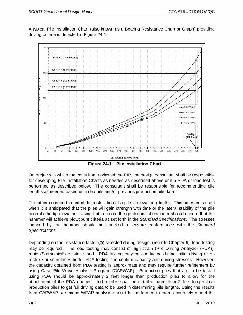
A typical Pile Installation Chart (also known as a Bearing Resistance Chart or Graph) providing driving criteria is depicted in Figure 24-1.
On projects in which the consultant reviewed the PIP, the design consultant shall be responsible for developing Pile Installation Charts as needed as described above or if a PDA or load test is performed as described below. The consultant shall be responsible for recommending pile lengths as needed based on index pile and/or previous production pile data. The other criterion to control the installation of a pile is elevation (depth). This criterion is used when it is anticipated that the piles will gain strength with time or the lateral stability of the pile controls the tip elevation. Using both criteria, the geotechnical engineer should ensure that the hammer will achieve blowcount criteria as set forth in the Standard Specifications. The stresses induced by the hammer should be checked to ensure conformance with the Standard Specifications. Depending on the resistance factor (φ) selected during design, (refer to Chapter 9), load testing may be required. The load testing may consist of high-strain (Pile Driving Analyzer (PDA)), rapid (Statnamic®) or static load. PDA testing may be conducted during initial driving or on restrike or sometimes both. PDA testing can confirm capacity and driving stresses. However, the capacity obtained from PDA testing is approximate and may require further refinement by using Case Pile Wave Analysis Program (CAPWAP). Production piles that are to be tested using PDA should be approximately 2 feet longer than production piles to allow for the attachment of the PDA gauges. Index piles shall be detailed more than 2 feet longer than production piles to get full driving data to be used in determining pile lengths. Using the results from CAPWAP, a second WEAP analysis should be performed to more accurately model the
Figure 24-1, Pile Installation Chart
SCDOT Geotechnical Design Manual CONSTRUCTION QA/QC
June 2010 24-3
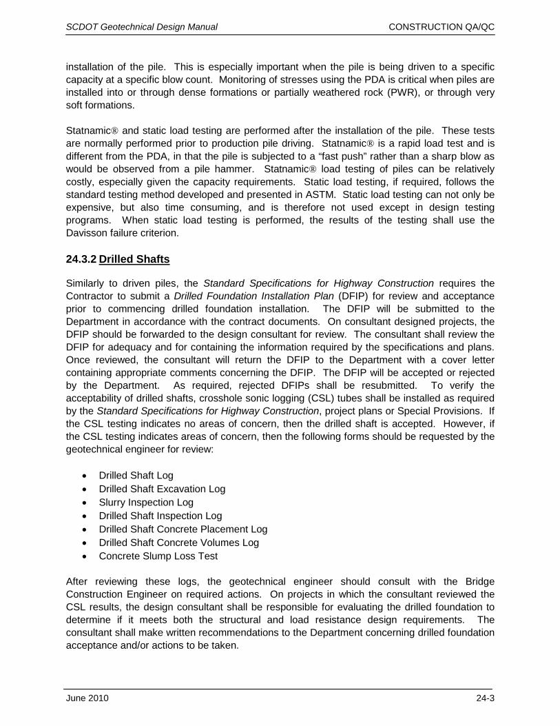
installation of the pile. This is especially important when the pile is being driven to a specific capacity at a specific blow count. Monitoring of stresses using the PDA is critical when piles are installed into or through dense formations or partially weathered rock (PWR), or through very soft formations. Statnamic® and static load testing are performed after the installation of the pile. These tests are normally performed prior to production pile driving. Statnamic® is a rapid load test and is different from the PDA, in that the pile is subjected to a “fast push” rather than a sharp blow as would be observed from a pile hammer. Statnamic® load testing of piles can be relatively costly, especially given the capacity requirements. Static load testing, if required, follows the standard testing method developed and presented in ASTM. Static load testing can not only be expensive, but also time consuming, and is therefore not used except in design testing programs. When static load testing is performed, the results of the testing shall use the Davisson failure criterion. 24.3.2
Similarly to driven piles, the Standard Specifications for Highway Construction requires the Contractor to submit a Drilled Foundation Installation Plan (DFIP) for review and acceptance prior to commencing drilled foundation installation. The DFIP will be submitted to the Department in accordance with the contract documents. On consultant designed projects, the DFIP should be forwarded to the design consultant for review. The consultant shall review the DFIP for adequacy and for containing the information required by the specifications and plans. Once reviewed, the consultant will return the DFIP to the Department with a cover letter containing appropriate comments concerning the DFIP. The DFIP will be accepted or rejected by the Department. As required, rejected DFIPs shall be resubmitted. To verify the acceptability of drilled shafts, crosshole sonic logging (CSL) tubes shall be installed as required by the Standard Specifications for Highway Construction, project plans or Special Provisions. If the CSL testing indicates no areas of concern, then the drilled shaft is accepted. However, if the CSL testing indicates areas of concern, then the following forms should be requested by the geotechnical engineer for review:
Drilled Shafts
• Drilled Shaft Log • Drilled Shaft Excavation Log • Slurry Inspection Log • Drilled Shaft Inspection Log • Drilled Shaft Concrete Placement Log • Drilled Shaft Concrete Volumes Log • Concrete Slump Loss Test
After reviewing these logs, the geotechnical engineer should consult with the Bridge Construction Engineer on required actions. On projects in which the consultant reviewed the CSL results, the design consultant shall be responsible for evaluating the drilled foundation to determine if it meets both the structural and load resistance design requirements. The consultant shall make written recommendations to the Department concerning drilled foundation acceptance and/or actions to be taken.
SCDOT Geotechnical Design Manual CONSTRUCTION QA/QC
24-4 June 2010
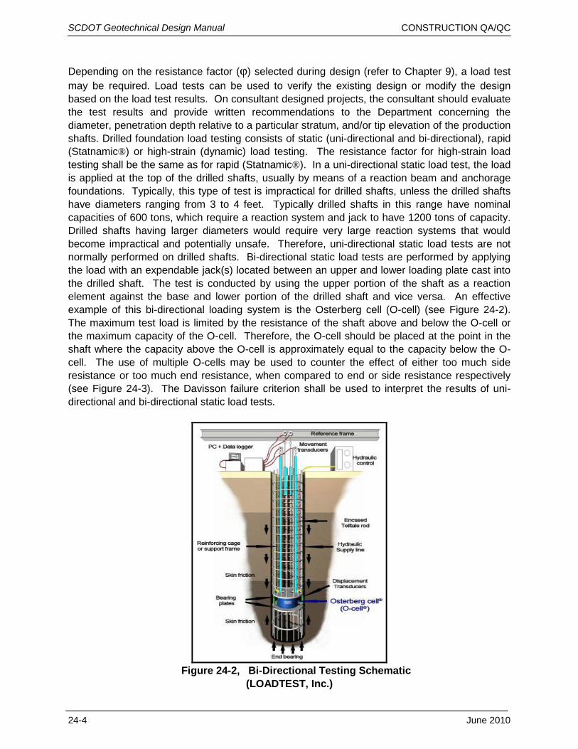
Depending on the resistance factor (φ) selected during design (refer to Chapter 9), a load test may be required. Load tests can be used to verify the existing design or modify the design based on the load test results. On consultant designed projects, the consultant should evaluate the test results and provide written recommendations to the Department concerning the diameter, penetration depth relative to a particular stratum, and/or tip elevation of the production shafts. Drilled foundation load testing consists of static (uni-directional and bi-directional), rapid (Statnamic®) or high-strain (dynamic) load testing. The resistance factor for high-strain load testing shall be the same as for rapid (Statnamic®). In a uni-directional static load test, the load is applied at the top of the drilled shafts, usually by means of a reaction beam and anchorage foundations. Typically, this type of test is impractical for drilled shafts, unless the drilled shafts have diameters ranging from 3 to 4 feet. Typically drilled shafts in this range have nominal capacities of 600 tons, which require a reaction system and jack to have 1200 tons of capacity. Drilled shafts having larger diameters would require very large reaction systems that would become impractical and potentially unsafe. Therefore, uni-directional static load tests are not normally performed on drilled shafts. Bi-directional static load tests are performed by applying the load with an expendable jack(s) located between an upper and lower loading plate cast into the drilled shaft. The test is conducted by using the upper portion of the shaft as a reaction element against the base and lower portion of the drilled shaft and vice versa. An effective example of this bi-directional loading system is the Osterberg cell (O-cell) (see Figure 24-2). The maximum test load is limited by the resistance of the shaft above and below the O-cell or the maximum capacity of the O-cell. Therefore, the O-cell should be placed at the point in the shaft where the capacity above the O-cell is approximately equal to the capacity below the O-cell. The use of multiple O-cells may be used to counter the effect of either too much side resistance or too much end resistance, when compared to end or side resistance respectively (see Figure 24-3). The Davisson failure criterion shall be used to interpret the results of uni-directional and bi-directional static load tests.
Figure 24-2, Bi-Directional Testing Schematic
(LOADTEST, Inc.)
SCDOT Geotechnical Design Manual CONSTRUCTION QA/QC
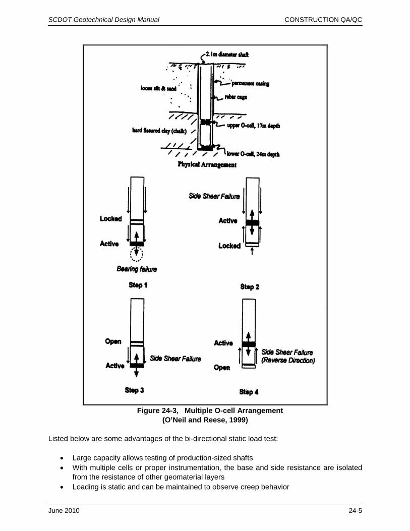
Figure 24-3, Multiple O-cell Arrangement
(O’Neil and Reese, 1999) Listed below are some advantages of the bi-directional static load test:
• Large capacity allows testing of production-sized shafts • With multiple cells or proper instrumentation, the base and side resistance are isolated
from the resistance of other geomaterial layers • Loading is static and can be maintained to observe creep behavior
June 2010 24-5
SCDOT Geotechnical Design Manual CONSTRUCTION QA/QC Following are some of the disadvantages of bi-directional static load testing:
• The test shaft must be preselected so that the O-cells can be included • It is not possible to test an existing shaft • For each installed device, testing is limited to failure of one part of the shaft only, unless
multiple O-cells are used • The performance of a production shaft subject to top down loading must be computed
and may require extrapolation of data in some cases • Limitations exist related to using a test shaft as a production shaft • The effect of upward directed loading compared to top down loading in a rock socket is
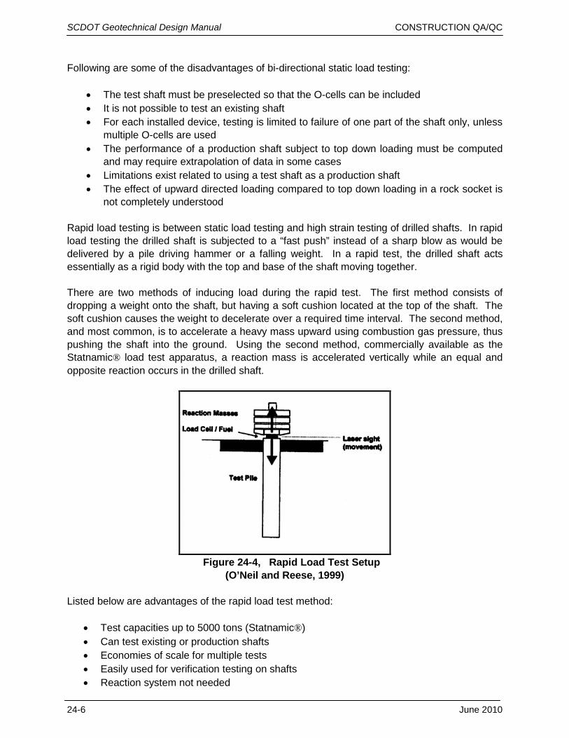
not completely understood Rapid load testing is between static load testing and high strain testing of drilled shafts. In rapid load testing the drilled shaft is subjected to a “fast push” instead of a sharp blow as would be delivered by a pile driving hammer or a falling weight. In a rapid test, the drilled shaft acts essentially as a rigid body with the top and base of the shaft moving together. There are two methods of inducing load during the rapid test. The first method consists of dropping a weight onto the shaft, but having a soft cushion located at the top of the shaft. The soft cushion causes the weight to decelerate over a required time interval. The second method, and most common, is to accelerate a heavy mass upward using combustion gas pressure, thus pushing the shaft into the ground. Using the second method, commercially available as the Statnamic® load test apparatus, a reaction mass is accelerated vertically while an equal and opposite reaction occurs in the drilled shaft.
Figure 24-4, Rapid Load Test Setup
(O’Neil and Reese, 1999) Listed below are advantages of the rapid load test method:
• Test capacities up to 5000 tons (Statnamic®) • Can test existing or production shafts • Economies of scale for multiple tests • Easily used for verification testing on shafts • Reaction system not needed
24-6 June 2010
SCDOT Geotechnical Design Manual CONSTRUCTION QA/QC
June 2010 24-7
Some disadvantages are:
• High capacity, but still limited compared to bi-directional tests • Rapid loading method, rate effects must be considered • Mobilization costs for reaction weights
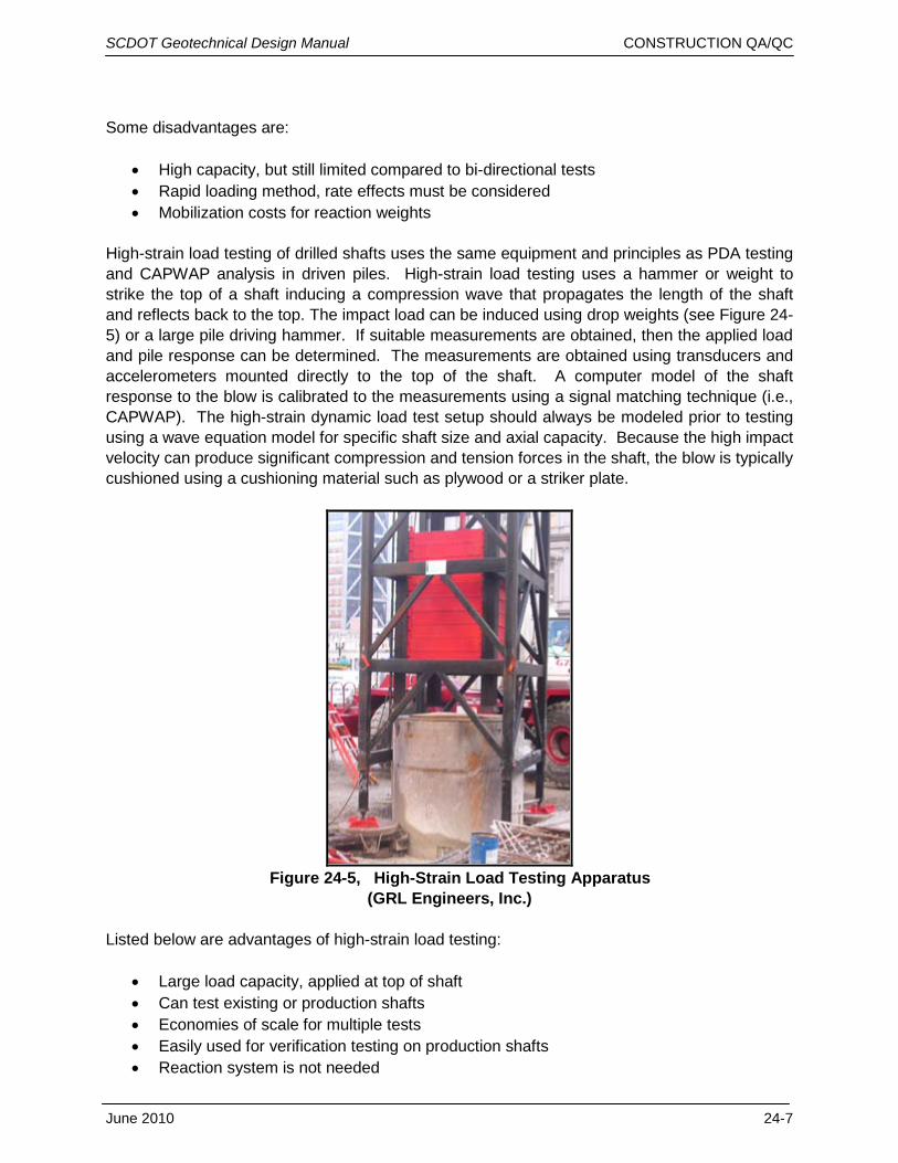
High-strain load testing of drilled shafts uses the same equipment and principles as PDA testing and CAPWAP analysis in driven piles. High-strain load testing uses a hammer or weight to strike the top of a shaft inducing a compression wave that propagates the length of the shaft and reflects back to the top. The impact load can be induced using drop weights (see Figure 24-5) or a large pile driving hammer. If suitable measurements are obtained, then the applied load and pile response can be determined. The measurements are obtained using transducers and accelerometers mounted directly to the top of the shaft. A computer model of the shaft response to the blow is calibrated to the measurements using a signal matching technique (i.e., CAPWAP). The high-strain dynamic load test setup should always be modeled prior to testing using a wave equation model for specific shaft size and axial capacity. Because the high impact velocity can produce significant compression and tension forces in the shaft, the blow is typically cushioned using a cushioning material such as plywood or a striker plate.
Figure 24-5, High-Strain Load Testing Apparatus
(GRL Engineers, Inc.) Listed below are advantages of high-strain load testing:
• Large load capacity, applied at top of shaft • Can test existing or production shafts • Economies of scale for multiple tests • Easily used for verification testing on production shafts • Reaction system is not needed
SCDOT Geotechnical Design Manual CONSTRUCTION QA/QC Some disadvantages are:
• Capacity high, but still limited compared to bi-directional tests • Test includes dynamic effects which must be considered • The applied force is interpreted from measurements on the shaft rather than from direct
measurement of load and therefore is sensitive to the shaft modulus, area, and uniformity in the top 1 to 1-1/2 diameters
• Test must be designed to avoid potential damage to the shaft from driving stresses • Mobilization costs for a large pile driving hammer or drop hammer • Changes in impedance along the length of the shaft can be confused with changes in
axial resistance, and therefore the impedance profile of the shaft must be reliably known. • There may be incomplete mobilization of base resistance at early blows and loss of side
resistance after multiple blows, and this issue complicates the interpretation of results. 24.4 GEOTECHNICAL INSTRUMENTATION
This Section discusses the interpretation of the results of geotechnical instrumentation; Chapter 25 discusses the requirements of the instrumentation, location of the instrumentation and monitoring of the instrumentation. The results obtained from geotechnical instrumentation require QA/QC to in order to determine if the data is meaningful. On projects in which the consultant reviews the results of geotechnical instrumentation, the design consultant shall be responsible for evaluating the geotechnical instrumentation data to determine if it meets the design requirements. The first questions concerning the results of geotechnical instrumentation is: “Was the data collected in a manner consistent with the plans, specifications and special provisions?” If the data was not collected in a consistent manner, every effort should be made to determine why not. If the data collected is consistent, next check to determine the numerical accuracy. Finally, the data should be checked for consistency with previous data. If the data is not consistent, does a hypothesis exist that explains all the data? If not, then consideration should be given to the point that the data is bad and should be discarded. The following Subsections will briefly discuss the interpretation of data collected from the various forms of geotechnical instrumentation. 24.4.1
The review of inclinometer data should indicate first that the bottom of the casing is placed firmly in material that is not moving (i.e., below the potential/actual failure surface). Second, the review should indicate that all subsequent data is indicating movement “down hill.” If the data indicates movement in the opposite direction, review the procedures for obtaining the data with field personnel. In addition, the actual movement data should be compared to the theoretical (design) movements to determine if the predicted is similar to the actual. From this comparison, it may be possible to predict additional movements.
Slope Inclinometers
24.4.2
The monitoring of settlement is probably the most common type of geotechnical instrumentation used by SCDOT. A variety of methods are used to monitor settlement (see Chapter 25). Typically settlement data consists of either survey (elevation) data or pore pressure data. Survey data is obtained from various points that are compared to established benchmarks,
Settlement Monitoring
24-8 June 2010
SCDOT Geotechnical Design Manual CONSTRUCTION QA/QC while pore pressure data is obtained from piezometers. This Section discusses the evaluation and reduction of the data, not the collection. The first check of the data is to determine if the numerical calculations are consistent. The second check and more important check, is the trend of the data, i.e. does the data continue to indicate downward movement. With pore pressure data, the second check is whether or not the pore pressures are approaching a static pore pressure level. It should be noted that the before construction pore pressure level will not be obtained, but some higher level will be. Both the survey data and the pore pressure data should approach a trend line where there is very little difference between readings. Once this happens, settlement is assumed to be over. While settlement monitoring is occurring, the amount of actual settlement should be compared to the predicted amount of settlement. One method for determining if settlement (based only on survey data) is complete is to use Taylor’s square root of time method. 24.4.3
The tiltmeter data should be reviewed to ascertain if any movement has occurred. If movement has occurred, does there appear to be a trend of continuing movement, or has the movement stopped? Tiltmeters should be left in place long enough to determine if the tilt reverses during seasonal changes.
Tiltmeters
24.4.4
According to
Vibration Monitoring
Ground Improvement Methods
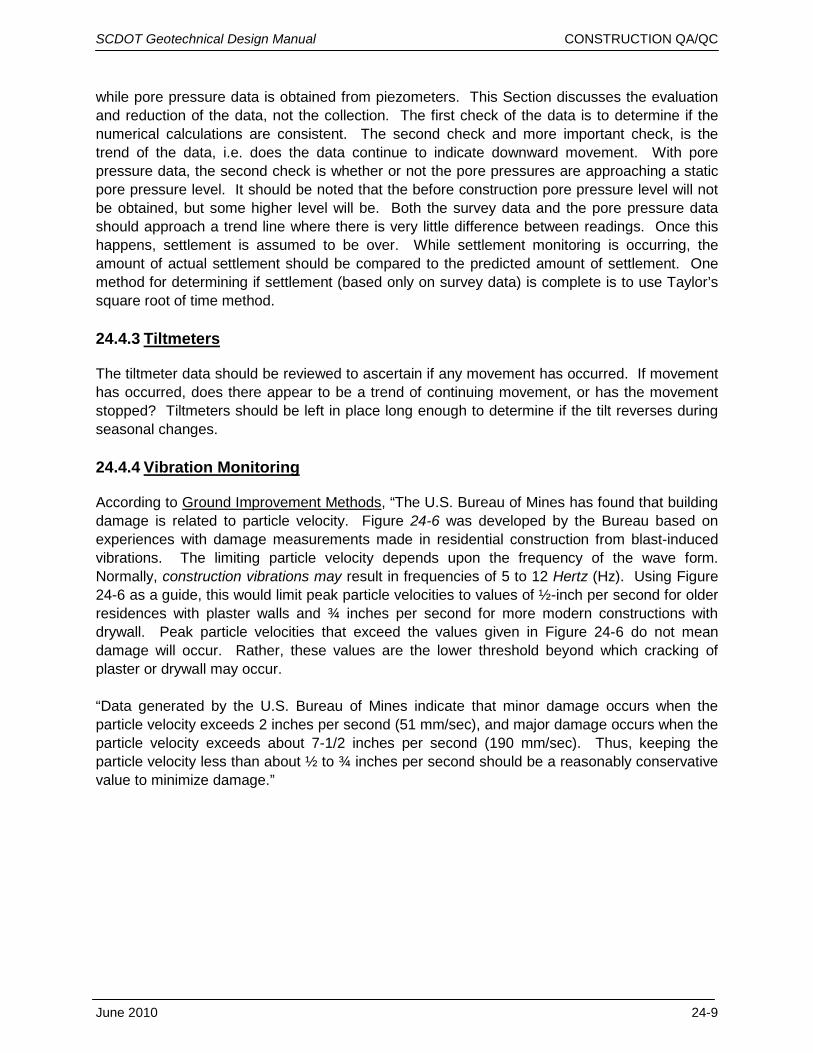
, “The U.S. Bureau of Mines has found that building damage is related to particle velocity. Figure 24-6 was developed by the Bureau based on experiences with damage measurements made in residential construction from blast-induced vibrations. The limiting particle velocity depends upon the frequency of the wave form. Normally, construction vibrations may result in frequencies of 5 to 12 Hertz (Hz). Using Figure 24-6 as a guide, this would limit peak particle velocities to values of ½-inch per second for older residences with plaster walls and ¾ inches per second for more modern constructions with drywall. Peak particle velocities that exceed the values given in Figure 24-6 do not mean damage will occur. Rather, these values are the lower threshold beyond which cracking of plaster or drywall may occur.
“Data generated by the U.S. Bureau of Mines indicate that minor damage occurs when the particle velocity exceeds 2 inches per second (51 mm/sec), and major damage occurs when the particle velocity exceeds about 7-1/2 inches per second (190 mm/sec). Thus, keeping the particle velocity less than about ½ to ¾ inches per second should be a reasonably conservative value to minimize damage.”
June 2010 24-9
SCDOT Geotechnical Design Manual CONSTRUCTION QA/QC
Figure 24-6, Safe Level of Vibrations for Houses
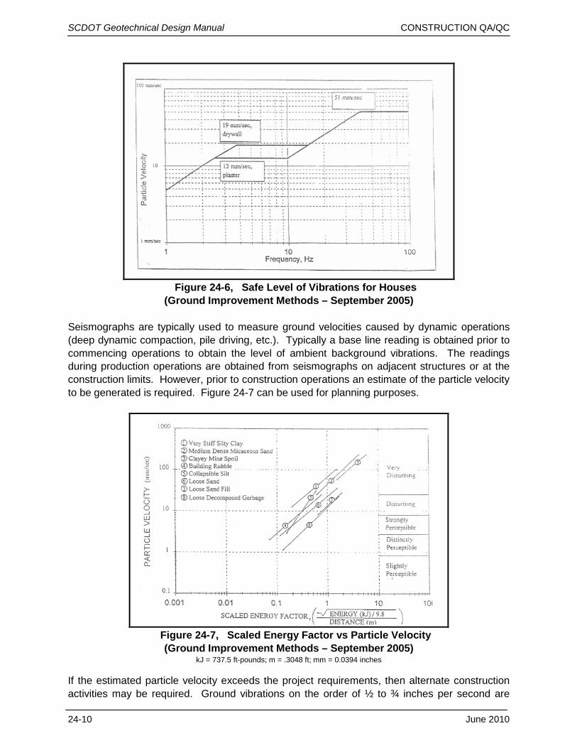
(Ground Improvement Methods – September 2005) Seismographs are typically used to measure ground velocities caused by dynamic operations (deep dynamic compaction, pile driving, etc.). Typically a base line reading is obtained prior to commencing operations to obtain the level of ambient background vibrations. The readings during production operations are obtained from seismographs on adjacent structures or at the construction limits. However, prior to construction operations an estimate of the particle velocity to be generated is required. Figure 24-7 can be used for planning purposes.
Figure 24-7, Scaled Energy Factor vs Particle Velocity (Ground Improvement Methods – September 2005)
kJ = 737.5 ft-pounds; m = .3048 ft; mm = 0.0394 inches
If the estimated particle velocity exceeds the project requirements, then alternate construction activities may be required. Ground vibrations on the order of ½ to ¾ inches per second are
24-10 June 2010
SCDOT Geotechnical Design Manual CONSTRUCTION QA/QC perceptible to humans. Even though these vibrations should not cause damage, vibrations of this magnitude can lead to complaints. The adjacent property owners should be educated concerning the potential impacts of the ground vibrations should be performed. 24.5 SHOP PLAN REVIEW
The Standard Specifications, Special Provisions, Supplemental Specifications and design drawings occasionally require the Contractor to submit Shop Plans and Installation Plans in addition to the PIP and the DFIP. The geotechnical engineer-of-record shall review the geotechnical portions of the submitted Shop Plans and Installation Plans for conformance to the Standard Specifications, Special Provisions, Supplemental Specifications and design drawings. If no review time is specified in the contract, then the geotechnical engineer-of-record shall conduct the review in twenty-one calendar days and shall submit the response to the Department. 24.6 REFERENCES
Elias, V., Welsh, J., Warren, J., Lukas, R., Collin, J.G., and Berg, R.R., (2005), Ground Improvement Methods, FHWA NHI-04-001, US Department of Transportation, Federal Highway Administration, Office of Bridge Technology, Washington, DC.
O’Neil, M. W. and Reese, L. C., (1999), Drilled Shafts: Construction Procedures and Design Methods
, FHWA-IF-99-025, US Department of Transportation, Federal Highway Administration, Office of Bridge Technology, Washington, DC.
South Carolina Department of Transportation, Standard Specifications for Highway Construction, 2007.
GRL Engineers, Inc., http://www.pile.com/grl/services/dlt/ LOADTEST, Inc., http://www.loadtest.co.uk/Loadtest%20Ltd/the%20osterberg%20cell_files/ocell.htm.
June 2010 24-11