chapter 28 book biomedical technology and devices handbook
DESCRIPTION
Capitulo 28 del libro Biomedical Technology and Devices Handbook, referido a Protesis Neuronales para Restablecer Movimientos.TRANSCRIPT

28
Neural Prostheses for
Movement Restoration
CONTENTS
28.1 Introduction
28.2 Skeletal Muscles — Movement Actuators
Structure of Skeletal Muscles • Activation of Skeletal Muscles • Contractile Force • Muscle Function
28.3 Functional Electrical Stimulation Principles
28.4 Instrumentation for FES
Electrodes • Electronic Stimulators • Sensors • Controller
28.5 Neural Prostheses for Restoring Upper and Lower Extremity Functions
Neural Prostheses for Reaching and Grasping • Neural Prostheses for Restoring Standing and Walking
References
28.1 Introduction
A neural prosthesis is an assistive system that replaces or augments a function that was lost or diminishedbecause of the injury or disease of the nervous system. The method most frequently applied in neuralprostheses (NP) is the external electrical activation of the appropriate impaired sensory-motor systems,that is, use of functional electrical stimulation (FES). FES elicits desired neural activation by deliveringthe controlled amount of electrical charge patterned as bursts of electrical charge pulses. In principle, itis possible to apply a time varying magnetic field, thereby inducing electrical currents within the selectedparts of the neural pathways; however, this technique is not yet efficient enough for functional activationof sensory-motor systems. A detailed presentation of most aspects of neural prosthesis can be found in
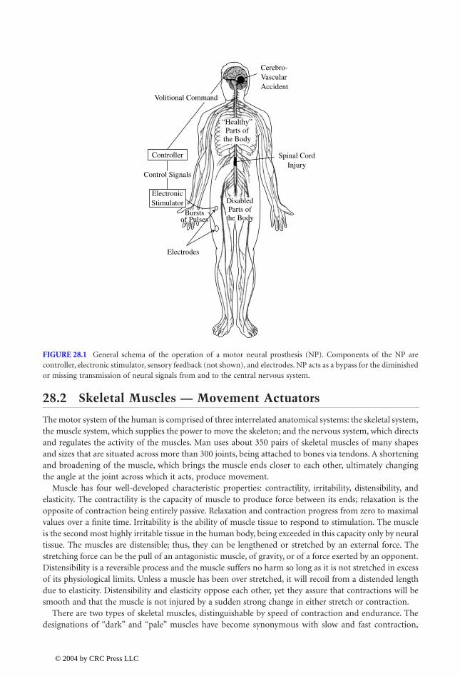
and Sinkjær (2000).Figure 28.1 shows the principle of FES-based neural prosthesis. After an injury or disease (e.g.,
stroke, spinal cord injury, Parkinson’s disease) of the central nervous system (CNS) or peripherallesion some sensory-motor systems will be intact, yet other structures will be paralyzed or paretic.A lesion leads to paralysis with the muscles still being innervated, but sometimes also to denervationof muscles. The innervated muscles are often activated in an unpredicted manner, but they are notcontrollable volitionally. These muscles are the best candidates for the effective neural prosthesisapplication. In parallel, many sensory pathways preserve their connections to the CNS, yet theiractivity does not reach the appropriate centers within the CNS. NP can also restore some elementsof the sensory systems. In other words, NP should be considered as a bypass of the damaged sensory-motor systems.
Popovic
Dejan B.
Aalborg University
Popovic
1140_bookreps.fm Page 1 Tuesday, July 15, 2003 9:47 AM
© 2004 by CRC Press LLC
28
-2
Biomedical Technology and Devices Handbook
28.2 Skeletal Muscles — Movement Actuators
The motor system of the human is comprised of three interrelated anatomical systems: the skeletal system,the muscle system, which supplies the power to move the skeleton; and the nervous system, which directsand regulates the activity of the muscles. Man uses about 350 pairs of skeletal muscles of many shapesand sizes that are situated across more than 300 joints, being attached to bones via tendons. A shorteningand broadening of the muscle, which brings the muscle ends closer to each other, ultimately changingthe angle at the joint across which it acts, produce movement.
Muscle has four well-developed characteristic properties: contractility, irritability, distensibility, andelasticity. The contractility is the capacity of muscle to produce force between its ends; relaxation is theopposite of contraction being entirely passive. Relaxation and contraction progress from zero to maximalvalues over a finite time. Irritability is the ability of muscle tissue to respond to stimulation. The muscleis the second most highly irritable tissue in the human body, being exceeded in this capacity only by neuraltissue. The muscles are distensible; thus, they can be lengthened or stretched by an external force. Thestretching force can be the pull of an antagonistic muscle, of gravity, or of a force exerted by an opponent.Distensibility is a reversible process and the muscle suffers no harm so long as it is not stretched in excessof its physiological limits. Unless a muscle has been over stretched, it will recoil from a distended lengthdue to elasticity. Distensibility and elasticity oppose each other, yet they assure that contractions will besmooth and that the muscle is not injured by a sudden strong change in either stretch or contraction.
There are two types of skeletal muscles, distinguishable by speed of contraction and endurance. Thedesignations of “dark” and “pale” muscles have become synonymous with slow and fast contraction,
FIGURE 28.1
General schema of the operation of a motor neural prosthesis (NP). Components of the NP arecontroller, electronic stimulator, sensory feedback (not shown), and electrodes. NP acts as a bypass for the diminishedor missing transmission of neural signals from and to the central nervous system.
Cerebro-VascularAccident
Volitional Command
Controller
Control Signals
Spinal CordInjury
ElectronicStimulator
Electrodes
DisabledParts of
the Body
“Healthy”Parts of
the Body
Burstsof Pulses
1140_bookreps.fm Page 2 Tuesday, July 15, 2003 9:47 AM
© 2004 by CRC Press LLC

Neural Prostheses for Movement Restoration
28
-3
respectively. In addition to a slower contraction/relaxation cycle, dark muscles have lower thresholds,tetanize at lower frequencies, fatigue less rapidly, and are more sensitive to stretch than the faster palemuscles. Most human striated muscles contain both types of fibers, but in differing proportions. Thepreponderantly slow-fibered muscles are the antigravity muscles, adapted for continuous body support.The predominantly fast-fibered muscles are phasic muscles, which produce quick postural changes andfine skilled movements.
28.2.1 Structure of Skeletal Muscles
A skeletal muscle is composed of two types of structural components: active contractile elements and inertcompliant materials. The contractile elements are contained within the muscle fibers. Each muscle iscomposed of many muscle fibers (a medium-sized muscle containing approximately 1 million fibers). Thefibers vary in length from a few millimeters to more than 40 cm, and their width is between 1 and 150
m
m. About 85% of the mass of a muscle consists of the muscle fibers, while the remaining 15% is composedlargely of connective tissues, which contain variable proportions of collagen, reticular, and elastic fibers.The connective tissues provide an arrangement of simple, spring-like elements (elastic components of themuscle), which exist both in series and in parallel with the contractile elements. A connective tissue sheath,the epimysium, surrounds the muscle and sends septa (the perimysia) into the muscle to envelop bundlesof muscle fibers. Larger bundles may be subdivided into several smaller bundles.
28.2.2 Activation of Skeletal Muscles
The muscle activation is linked to activity of neural cells. The essential function of a nerve cell is totransmit excitation to other cells, and it is achieved by releasing a chemical transmitter substance at itssynaptic terminal. A number of different kinds of stimuli may excite neurons. The normal stimulus forsynaptic neurons is the action upon their membranes of chemical transmitters released by other neurons.Stimulation of receptor neurons is normally provided by chemical, thermal, mechanical, and electro-magnetic energies. In a few instances, rare among the vertebrates, a neuron is stimulated by directelectrical stimulation from another neuron.
As the action potential travels along the fiber surface, it consists of a wave of negativity followed byan area of gradually recovering positivity. While an area is in its reversed (active) state, it is absolutelyrefractory and cannot be restimulated. During recovery, the membrane is relatively refractory, a statethat lasts many times longer than the absolute refractory period. Intense or sustained stimuli mayrestimulate the original site during repolarization. During the relative refractory period both theamplitude and velocity of the neural spike are altered, reflecting changed conditions in the fiber. Insome neurons the latter portion of the downward course of the spike is considerably less rapid thanits rise. During this period of 12 to 80 msec, the membrane is hyperexcitable or supernormal, hencemore easily restimulated.
Neurons normally carry trains of impulses. In general, natural stimuli are of sufficient duration toreactivate the membrane after the absolute refractory period. A single electric shock may produce a singleaction potential, but only because its duration does not outlast the refractory period of the fiber. Thestronger the stimulus, the earlier it will reexcite, and the shorter will be the time span between impulses,hence, the greater the frequency.
Because each action potential is followed by an absolute refractory period, action potentials cannotsummate, but remain separate and discrete. The neurons do not conduct impulses at rates as high as theabsolute refractory periods would suggest. A fiber with spikes lasting about 0.4 msec might be expectedto conduct impulses at a frequency of 2500/sec, but its upper limit will be closer to 1000/sec. Conductionfrequencies rarely approximate their possible maxima. Motoneurons usually conduct at frequencies of20 to 40 (rarely as high as 50) impulses per second although, at the start of a maximum contraction,rates greater than 100 Hz have been recorded. Upper-limit frequencies for sensory neurons normally liebetween 100 and 200 impulses per second, although auditory neurons may conduct between 800 and
1140_bookreps.fm Page 3 Tuesday, July 15, 2003 9:47 AM
© 2004 by CRC Press LLC

28
-4
Biomedical Technology and Devices Handbook
1000 impulses per second. Information is conveyed by the presence or absence of an action potential, aswell as by the frequency of action potentials.
Velocity of conduction depends not only on myelination but also, more importantly, on the diameterof the fiber. It can be fairly accurately said that the conduction velocity is proportional to the diameterof the axon, and is in the range of 50 m/sec. The largest motor and sensory nerve fibers (diameters about20
m
m) have conduction velocities up to 120 m/sec. In small unmyelinated fibers, the velocities are from0.7 to 2 m/sec. Large fibers have lower stimulus thresholds compared with small fibers.
Nerve fibers are classified into three major groups, A, B, and C, on the basis of conduction velocities.Group C contains the unmyelinated postganglionic fibers and group B the small myelinated preganglionicfibers of the autonomic nervous system. Group A includes the large, rapidly conducting myelinatedsomatic fibers. Group A has been further divided into four subgroups:
a
,
b
,
g
, and
d,
based on the velocityand diameter.
Nerves enter the muscle near the main arterial branch and divide to distribute both motor and sensoryfibers to the muscle bundles. Motor fibers fall into two categories: large fibers (alpha subdivision of GroupA) and smaller fibers (gamma subdivision of Group A). Each large alpha motorneuron, with its cell bodylying in the ventral horn of the spinal cord, supplies a number of muscle fibers by successive bifurcationof its axis cylinder. One motorneuron and all of the muscle fibers that are innervated with the axonterminals constitute a motor unit. The number of muscle fibers per motor unit varies considerably withboth the size of the muscle and the type of its function. Small muscles and muscles concerned with finegradations of contraction have necessarily smaller motor units than larger bulky muscles whose job isthe maintenance of strong contraction.
The excitation of a muscle (contraction) is accomplished by the nervous system: nerve impulsesarriving at the neuromuscular junction cause the release of a transmitter substance, which diffuses acrossthe junction and chemically excites the muscle fiber. Action potentials travel along the fiber membraneat a speed of 1 to 3 m/sec and initiate the events that lead to shortening of the contractile elements ofthe myofibrils and the consequent production of force in the muscle.
Muscle fibers are incapable of lengthening themselves actively.
28.2.3 Contractile Force
The force developed by a contracting muscle is influenced by a number of factors such as the character-istics of the stimulus, the length of the muscle both at the time of stimulation and during the contraction,and the speed at which the muscle is contracting.
Most of what has been learned about muscle has been derived from studies using stimulation byelectrical pulses. When a single pulse is applied directly to a motorneuron, the corresponding musclefiber will respond in an all-or-none fashion. Increasing the intensity of the pulse will not increasethe magnitude of the fiber’s response. It is important to mention here that the all-or-none responseof the muscle fiber is determined by the all-or-none character of its excitation and not by any all-or-none limitations inherent in the contractile mechanism itself. When a single adequate pulse is appliedto a whole muscle, the muscle will respond with a quick contraction, followed immediately byrelaxation. Such a response is called a twitch. Its magnitude will vary with the number of musclefibers, which respond to the stimulus, and this will vary directly with the intensity of the pulse upto a finite maximal intensity.
The twitch is an indication of force development by the muscle. After a short latent period, the forcebecomes evident and rises to a peak, then declines over a slightly longer time course to zero. The timecourse of the development of force in the twitch is influenced by the interaction of the contractilecomponents of the muscle fibrils with the elastic components of the muscle.
A single electrical pulse must have a certain minimal intensity to be effective. This minimal level is aninverse measure of the irritability of the tissue; the smaller the minimal intensity, the greater the irritability.The minimal effective intensity is designated the threshold or minimal stimulus. These terms refer to theweakest stimulus, which will evoke a barely perceptible response. Subthreshold and subliminal refer to
1140_bookreps.fm Page 4 Tuesday, July 15, 2003 9:47 AM
© 2004 by CRC Press LLC
Neural Prostheses for Movement Restoration
28
-5
a stimulus of inadequate intensity. As the intensity of the single pulse is increased above the minimum,the contractile force in the muscle increases progressively as a result of the activation of more and moremuscle fibers. Finally, the intensity is reached that evokes the maximal response of which the muscle iscapable. Presumably all fibers are then active. The weakest stimulus intensity that evokes maximalcontraction is called the maximal stimulus.
A weak but adequate pulse with a rapid rate of rise from zero to its preset intensity will evoke a strongercontraction than a pulse of the same intensity with a slower rise. A minimal rate is required even for anintense stimulus. If intensity rises too gradually, there will be no response at all; the stimulus is thenineffectual. For any stimulus of adequate intensity, the more abruptly it is applied the greater will be theresponse it evokes within the limits of the muscle’s capacity. The greater the intensity, the less rapidly itneeds rise to produce a given level of response.
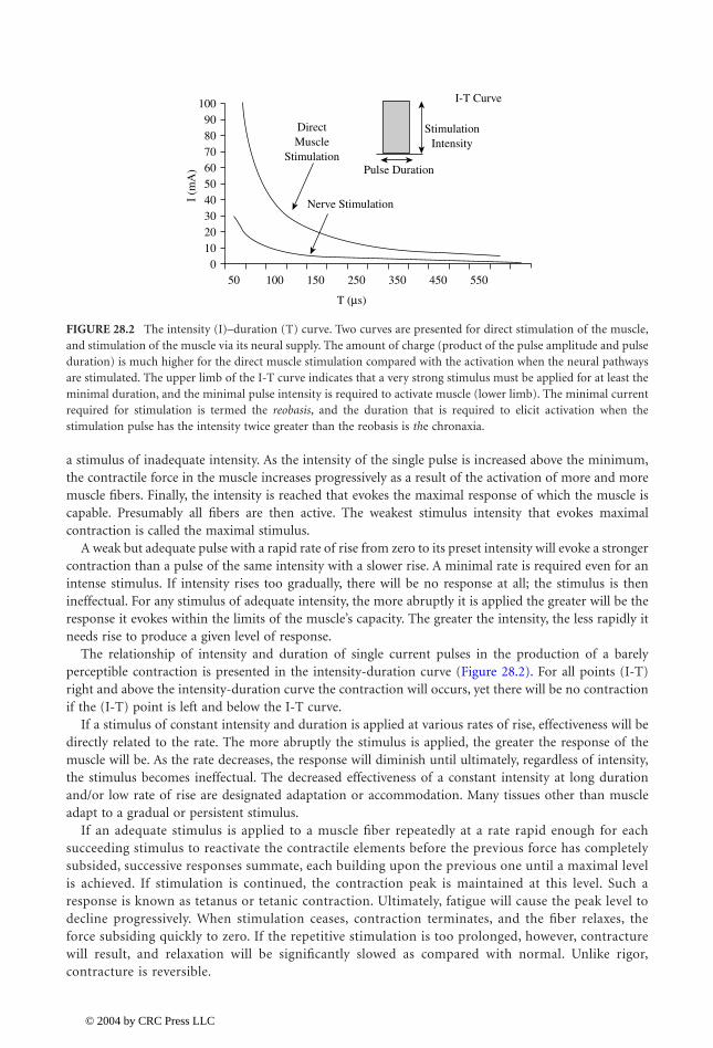
The relationship of intensity and duration of single current pulses in the production of a barelyperceptible contraction is presented in the intensity-duration curve (Figure 28.2). For all points (I-T)right and above the intensity-duration curve the contraction will occurs, yet there will be no contractionif the (I-T) point is left and below the I-T curve.
If a stimulus of constant intensity and duration is applied at various rates of rise, effectiveness will bedirectly related to the rate. The more abruptly the stimulus is applied, the greater the response of themuscle will be. As the rate decreases, the response will diminish until ultimately, regardless of intensity,the stimulus becomes ineffectual. The decreased effectiveness of a constant intensity at long durationand/or low rate of rise are designated adaptation or accommodation. Many tissues other than muscleadapt to a gradual or persistent stimulus.
If an adequate stimulus is applied to a muscle fiber repeatedly at a rate rapid enough for eachsucceeding stimulus to reactivate the contractile elements before the previous force has completelysubsided, successive responses summate, each building upon the previous one until a maximal levelis achieved. If stimulation is continued, the contraction peak is maintained at this level. Such aresponse is known as tetanus or tetanic contraction. Ultimately, fatigue will cause the peak level todecline progressively. When stimulation ceases, contraction terminates, and the fiber relaxes, theforce subsiding quickly to zero. If the repetitive stimulation is too prolonged, however, contracturewill result, and relaxation will be significantly slowed as compared with normal. Unlike rigor,contracture is reversible.
FIGURE 28.2
The intensity (I)–duration (T) curve. Two curves are presented for direct stimulation of the muscle,and stimulation of the muscle via its neural supply. The amount of charge (product of the pulse amplitude and pulseduration) is much higher for the direct muscle stimulation compared with the activation when the neural pathwaysare stimulated. The upper limb of the I-T curve indicates that a very strong stimulus must be applied for at least theminimal duration, and the minimal pulse intensity is required to activate muscle (lower limb). The minimal currentrequired for stimulation is termed the
reobasis
, and the duration that is required to elicit activation when thestimulation pulse has the intensity twice greater than the reobasis is
th
e chronaxia.
050 100 150
T (µs)
250 350 450 550
10203040I
(mA
)50
Nerve Stimulation
DirectMuscle
StimulationPulse Duration
StimulationIntensity
I-T Curve
60708090
100
1140_bookreps.fm Page 5 Tuesday, July 15, 2003 9:47 AM
© 2004 by CRC Press LLC
28
-6
Biomedical Technology and Devices Handbook
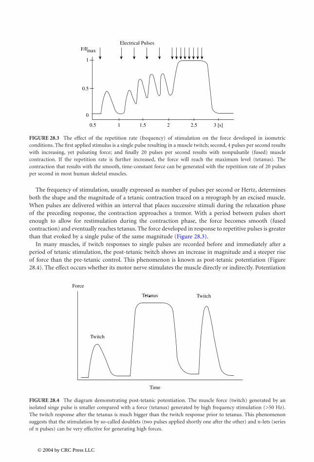
The frequency of stimulation, usually expressed as number of pulses per second or Hertz, determinesboth the shape and the magnitude of a tetanic contraction traced on a myograph by an excised muscle.When pulses are delivered within an interval that places successive stimuli during the relaxation phaseof the preceding response, the contraction approaches a tremor. With a period between pulses shortenough to allow for restimulation during the contraction phase, the force becomes smooth (fusedcontraction) and eventually reaches tetanus. The force developed in response to repetitive pulses is greaterthan that evoked by a single pulse of the same magnitude (Figure 28.3).
In many muscles, if twitch responses to single pulses are recorded before and immediately after aperiod of tetanic stimulation, the post-tetanic twitch shows an increase in magnitude and a steeper riseof force than the pre-tetanic control. This phenomenon is known as post-tetanic potentiation (Figure28.4). The effect occurs whether its motor nerve stimulates the muscle directly or indirectly. Potentiation
FIGURE 28.3
The effect of the repetition rate (frequency) of stimulation on the force developed in isometricconditions. The first applied stimulus is a single pulse resulting in a muscle twitch; second, 4 pulses per second resultswith increasing, yet pulsating force; and finally 20 pulses per second results with nonpulsatile (fused) musclecontraction. If the repetition rate is further increased, the force will reach the maximum level (tetanus). Thecontraction that results with the smooth, time-constant force can be generated with the repetition rate of 20 pulsesper second in most human skeletal muscles.
FIGURE 28.4
The diagram demonstrating post-tetanic potentiation. The muscle force (twitch) generated by anisolated singe pulse is smaller compared with a force (tetanus) generated by high frequency stimulation (>50 Hz).The twitch response after the tetanus is much bigger than the twitch response prior to tetanus. This phenomenonsuggests that the stimulation by so-called doublets (two pulses applied shortly one after the other) and n-lets (seriesof n pulses) can be very effective for generating high forces.
0.5
0
0.5
1
F/FElectrical Pulses
1 1.5 2 2.5 3 [s]
max
Force
Twitch
Time
Twitch
1140_bookreps.fm Page 6 Tuesday, July 15, 2003 9:47 AM
© 2004 by CRC Press LLC

Neural Prostheses for Movement Restoration
28
-7
is maximal shortly after the repetitive stimulation and then decays exponentially at a rate that is dependenton both the frequency of pulses and the number delivered in the train. Short trains produce potentiationwithout any alteration of the twitch duration, but longer trains result in lengthening of the contractiontime and of the half-relaxation time (the time required for force to drop to 50% of its peak value).
The most obvious property of the muscle is its capacity to develop force against resistance. The lengthof the muscle at the time of activation markedly affects its ability to develop force and to perform externalwork. When a muscle contracts, the contractile material itself shortens, but whether the whole muscleshortens or not depends on the relation of the internal force developed by the muscle to the externalforce exerted by the resistance or load.
Three types of muscle contraction are distinguished according to the length change, induced by therelationship of internal and external forces: isometric, isotonic, and isokinetic. Isometric contractionrefers to the case where no change of length occurs, isotonic to the case where the force is kept constant,and isokinetic when the velocity of shortening is kept constant.
The initial length of a muscle, that is, its length at the time of stimulation, influences the magnitudeof its contractile response to a given stimulus. A stretched muscle contracts more forcefully than whenit is unstretched at the time of activation. This is true whether the contraction is isometric, isotonic, orisokinetic. Within physiological limits, the greater the initial length, the greater the force capability ofthe muscle will be. Parallel-fibered muscles exert maximal total force at lengths only slightly greater thanrest length. Muscles with other fiber arrangements have maxima at somewhat greater relative stretch. Ingeneral, optimal length is close to the maximal body length of the muscle, that is, the greatest length thatthe muscle can attain in the normal living body. This is about 1.2 to 1.3 times the rest length of themuscle. Force capability is less at short and long lengths. Therefore, a muscle can exert the greatest forceor sustain the heaviest load when the body position is such as to bring it to its optimal length. In isotoniccontractions the increased force and longer length permit greater shortening; hence, more work can bedone or, alternatively, the same work can be done at lower energy cost.
The relationship of force to muscle length may be presented graphically in the form of a force-lengthcurve, in which force in an isolated muscle are plotted against a series of muscle lengths from less thanto greater than the resting length (Figure 28.5). Both the passive elastic force (Curve 1) exerted by theelastic components in the passively stretched muscle and the total force (Curve 2) exerted by the activelycontracting muscle are plotted.
Most isolated unloaded muscles normally shorten by about 50% or less of their rest length. The absoluteamount by which any muscle can shorten depends upon the length and arrangement of its fibers, thegreatest shortening occurring in the long parallel-fiber muscles such as the
Biceps m
. and
Sartorius m
.
FIGURE 28.5
Force vs
.
length curve for an isolated muscle. (1) Passive elastic tension, (2) total force, and (3) forceobtained by subtracting of passive force from total force. This curves suggests that the muscle force depends on theposition of the joint. Maximum force can be generated at muscle lengths that are shorter than the relaxed length ofthe muscle (this length varies from muscle to muscle).
0
50 100% of the Resting Length
150
1
2 Tt
T = Tt−Tp
20
40
60
80
100
% Force
Tp
3
1140_bookreps.fm Page 7 Tuesday, July 15, 2003 9:47 AM
© 2004 by CRC Press LLC

28
-8
Biomedical Technology and Devices Handbook
In intact muscle, the structure of joints, the resistance of antagonists, and any load that opposes themuscle further limit shortening. When shortening against resistance, speed varies inversely with the load.Therefore, in isotonic contraction the less the resistance, the more nearly maximal the rate of shortening.When a muscle is required to shorten more rapidly against the same load, less force is produced thanwhen it shortens more slowly.
In concentric contraction the relationship is evidenced by the decrease in velocity as the load isincreased. Shortening velocity is maximal with zero load and reflects the intrinsic shortening speed ofthe contractile material. Velocity reaches zero with a load too great for the muscle to lift; contraction isthen isometric and maximal force can be produced. When more muscle fibers are activated than areneeded to overcome the load, the excess force is converted into increasing velocity and therefore greaterdistance of movement.
In eccentric contraction, values for shortening velocity become negative, and the muscle’s ability tosustain force increases with increased speed of lengthening, but not to the extent that might be expectedfrom extrapolation of the shortening curve (Figure 28.6).
28.2.4 Muscle Function
Motor skill and all forms of movement result from the interaction of muscular force, gravity, and anyother external forces, which impinge on skeletal levers. The muscles rarely act singly; rather, groups ofmuscles interact in many ways so that the desired movement is accomplished. This interaction may takemany different forms so that a muscle may serve in a number of different capacities, depending on themovement. Whenever a muscle causes movement by shortening, it is functioning as a mover or agonist.If the observed muscle makes the major contribution to the movement, that muscle is named as theprime mover. Other muscles crossing the same joint on the same aspect, but which are smaller or whichare shown electromyographically to make a lesser contribution to the movement under consideration,are identified as secondary or assistant movers or agonists. The muscles whose action are opposite toand so may oppose that of a prime mover are called antagonists. This does not mean that an antagonist,as the name implies, always exerts force against the prime mover; electromyography has demonstratedconclusively an absence of electrical activity in opposing muscles.
Synergistic action has been defined as cooperative action of two or more muscles in the productionof a desired movement. A synergist, then, may be regarded as a muscle that cooperates with the primemover so as to enhance the movement. Synergic interaction may take many forms and variations asdiscussed below. Two muscles acting together to produce a movement, which neither could producealone, may be classed as conjoint synergists. Dorsiflexion of the foot at the ankle is an example. The
FIGURE 28.6
Relationship among the normalized muscle force and velocity of contraction. Negative velocity relatesto eccentric contraction, while the positive to active contraction. The faster the shortening, the smaller is the force,and vice versa. See text for details.
0.3
−20
−10
0
10
20
30
40
50 Velocity of Shortening (m/s)
0.6 0.9 1.3
Force/Force (max)
1140_bookreps.fm Page 8 Tuesday, July 15, 2003 9:47 AM
© 2004 by CRC Press LLC

Neural Prostheses for Movement Restoration
28
-9
movement is produced by the combined action of the
Tibialis Anterior m.
and the
Extensor DigitorumLongus m
. The
Tibialis anterior m
. alone would produce a combination of dorsiflexion and inversion,while shortening of the
Extensor Digitorum Longus m.
alone would produce toe extension, dorsiflexion,and eversion. Acting together, the muscles produce a movement of pure dorsiflexion. Another exampleoccurs in lateral deviation of the hand at the wrist; e.g., ulnar deviation results from the simultaneousaction of the
Flexor Carpi Ulnaris m.
and the
Extensor
Carpi Ulnaris m.
The
sine qua non
of an effective coordinate movement involves greater stabilization of the moreproximal joints so that the distal segments move effectively. The greater the amount of force to be exertedby the open end of a kinematic chain (whether it is the peripheral end of an upper or of a lower extremity),the greater the amount of stabilizing force that is needed at the proximal links.
When a joint is voluntarily fixed rather than stabilized, there is, in addition to immobilization, a rigidityor stiffness resulting from the strong isometric contraction of all muscles crossing that joint. Thesemuscles will forcefully resist all external efforts to move that joint. As fixation can be very tiring, it isseldom used and rarely useful. From the above discussion one should recognize the difference betweenstabilization and fixation of joints. As stated, fixation denotes a rigidity or stiffness in opposition to allmovement, whereas stabilization implies only firmness. Economy of movement involves the use ofminimal stabilizing synergy and no fixation of joints.
A muscle crossing two or more joints has certain characteristics, capabilities, and limitations whencompared with those muscles that cross only one joint. When a muscle crosses more than one joint, itcreates force moments at each of the joints crossed whenever it generates force. The moments of forceit exerts at any given instant depend on two factors: the instantaneous length of the moment arm at eachjoint and the corresponding amount of force that the muscle is exerting. The joint with the longestmoment arm, and hence with the greatest moment of force, is normally the one at which the multiactuatormuscle will produce or regulate the most action. For example, the
Hamstrings m.
has the moment armat the hip at least 50% longer than the one at the knee; thus, it contributes more to knee flexion then tohip extension.
28.3 Functional Electrical Stimulation Principles
The literature dealing with electrical stimulation frequently uses terms other than FES, such as neu-romuscular stimulation (NMS) and functional neuromuscular stimulation (FNS), aiming to preciselydescribe the structures that are activated by electrical stimulation. The term FES is used throughoutthis chapter.
FES systems aim to achieve sensory-motor integration; thereby a better function of humans withparalysis or paresis. FES activates motoneurons or reflex pathways by stimulating efferent or afferentnerve fibers, respectively.
FES can be delivered using monopolar or bipolar configuration. In the bipolar configuration twoelectrodes are positioned in the vicinity of the muscle that should be stimulated. In the monopolarconfiguration active electrodes (cathodes) are positioned in the vicinity of the structures to be stimulated,while a single common electrode (anode) is positioned distant to the stimulated structure, yet somewherealong the neural pathway to the CNS.
FES delivers trains of the electrical charge pulses, mimicking to an extent the natural flow of excitationsignals generated by the CNS in nonimpaired structures. FES operation can be modeled with a relativelysimple electric circuit: generator, electrodes, and tissue. The tissue is an ionic conductor with an imped-ance of about 10 to 100
W
, and electrodes are capacitive conductors whose electrical properties dependon many variables, but their impedance is from 500
W
to 5 k
W
, and they induce a phase shift of about10 to 30°. The generator can work as a current or voltage regulated device.
The amplitude and duration of stimulus pulses, output impedance of the generator, and impedanceof electrodes determine the electrical charge that will be delivered to neuromuscular structure. Stimulatorsare usually referred to as constant-current or constant-voltage devices. High-output impedance deviceswill deliver the desired current to the tissue, regardless of the changes in electrode properties up to the
1140_bookreps.fm Page 9 Tuesday, July 15, 2003 9:47 AM
© 2004 by CRC Press LLC
28
-10
Biomedical Technology and Devices Handbook
voltage capacity available. These constant-current stimulators should be correctly termed current-regu-lated stimulators.
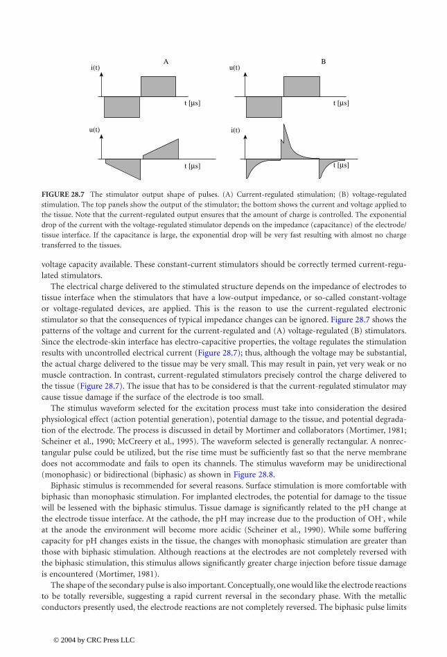
The electrical charge delivered to the stimulated structure depends on the impedance of electrodes totissue interface when the stimulators that have a low-output impedance, or so-called constant-voltageor voltage-regulated devices, are applied. This is the reason to use the current-regulated electronicstimulator so that the consequences of typical impedance changes can be ignored. Figure 28.7 shows thepatterns of the voltage and current for the current-regulated and (A) voltage-regulated (B) stimulators.Since the electrode-skin interface has electro-capacitive properties, the voltage regulates the stimulationresults with uncontrolled electrical current (Figure 28.7); thus, although the voltage may be substantial,the actual charge delivered to the tissue may be very small. This may result in pain, yet very weak or nomuscle contraction. In contrast, current-regulated stimulators precisely control the charge delivered tothe tissue (Figure 28.7). The issue that has to be considered is that the current-regulated stimulator maycause tissue damage if the surface of the electrode is too small.
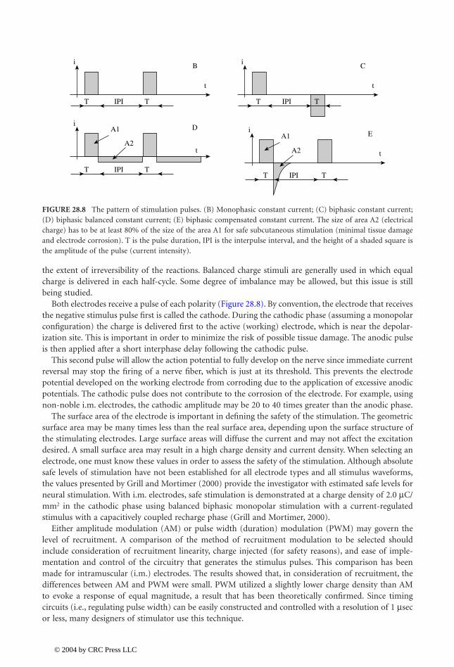
The stimulus waveform selected for the excitation process must take into consideration the desiredphysiological effect (action potential generation), potential damage to the tissue, and potential degrada-tion of the electrode. The process is discussed in detail by Mortimer and collaborators (Mortimer, 1981;Scheiner et al., 1990; McCreery et al., 1995). The waveform selected is generally rectangular. A nonrec-tangular pulse could be utilized, but the rise time must be sufficiently fast so that the nerve membranedoes not accommodate and fails to open its channels. The stimulus waveform may be unidirectional(monophasic) or bidirectional (biphasic) as shown in Figure 28.8.
Biphasic stimulus is recommended for several reasons. Surface stimulation is more comfortable withbiphasic than monophasic stimulation. For implanted electrodes, the potential for damage to the tissuewill be lessened with the biphasic stimulus. Tissue damage is significantly related to the pH change atthe electrode tissue interface. At the cathode, the pH may increase due to the production of OH
-
, whileat the anode the environment will become more acidic (Scheiner et al., 1990). While some bufferingcapacity for pH changes exists in the tissue, the changes with monophasic stimulation are greater thanthose with biphasic stimulation. Although reactions at the electrodes are not completely reversed withthe biphasic stimulation, this stimulus allows significantly greater charge injection before tissue damageis encountered (Mortimer, 1981).
The shape of the secondary pulse is also important. Conceptually, one would like the electrode reactionsto be totally reversible, suggesting a rapid current reversal in the secondary phase. With the metallicconductors presently used, the electrode reactions are not completely reversed. The biphasic pulse limits
FIGURE 28.7
The stimulator output shape of pulses. (A) Current-regulated stimulation; (B) voltage-regulatedstimulation. The top panels show the output of the stimulator; the bottom shows the current and voltage applied tothe tissue. Note that the current-regulated output ensures that the amount of charge is controlled. The exponentialdrop of the current with the voltage-regulated stimulator depends on the impedance (capacitance) of the electrode/tissue interface. If the capacitance is large, the exponential drop will be very fast resulting with almost no chargetransferred to the tissues.
Ai(t)
u(t)
t [µs]
t [µs]
Bu(t)
i(t)
t [µs]
t [µs]
1140_bookreps.fm Page 10 Tuesday, July 15, 2003 9:47 AM
© 2004 by CRC Press LLC
Neural Prostheses for Movement Restoration
28
-11
the extent of irreversibility of the reactions. Balanced charge stimuli are generally used in which equalcharge is delivered in each half-cycle. Some degree of imbalance may be allowed, but this issue is stillbeing studied.
Both electrodes receive a pulse of each polarity (Figure 28.8). By convention, the electrode that receivesthe negative stimulus pulse first is called the cathode. During the cathodic phase (assuming a monopolarconfiguration) the charge is delivered first to the active (working) electrode, which is near the depolar-ization site. This is important in order to minimize the risk of possible tissue damage. The anodic pulseis then applied after a short interphase delay following the cathodic pulse.
This second pulse will allow the action potential to fully develop on the nerve since immediate currentreversal may stop the firing of a nerve fiber, which is just at its threshold. This prevents the electrodepotential developed on the working electrode from corroding due to the application of excessive anodicpotentials. The cathodic pulse does not contribute to the corrosion of the electrode. For example, usingnon-noble i.m. electrodes, the cathodic amplitude may be 20 to 40 times greater than the anodic phase.
The surface area of the electrode is important in defining the safety of the stimulation. The geometricsurface area may be many times less than the real surface area, depending upon the surface structure ofthe stimulating electrodes. Large surface areas will diffuse the current and may not affect the excitationdesired. A small surface area may result in a high charge density and current density. When selecting anelectrode, one must know these values in order to assess the safety of the stimulation. Although absolutesafe levels of stimulation have not been established for all electrode types and all stimulus waveforms,the values presented by Grill and Mortimer (2000) provide the investigator with estimated safe levels forneural stimulation. With i.m. electrodes, safe stimulation is demonstrated at a charge density of 2.0
m
C/mm
2
in the cathodic phase using balanced biphasic monopolar stimulation with a current-regulatedstimulus with a capacitively coupled recharge phase (Grill and Mortimer, 2000).
Either amplitude modulation (AM) or pulse width (duration) modulation (PWM) may govern thelevel of recruitment. A comparison of the method of recruitment modulation to be selected shouldinclude consideration of recruitment linearity, charge injected (for safety reasons), and ease of imple-mentation and control of the circuitry that generates the stimulus pulses. This comparison has beenmade for intramuscular (i.m.) electrodes. The results showed that, in consideration of recruitment, thedifferences between AM and PWM were small. PWM utilized a slightly lower charge density than AMto evoke a response of equal magnitude, a result that has been theoretically confirmed. Since timingcircuits (i.e., regulating pulse width) can be easily constructed and controlled with a resolution of 1
m
secor less, many designers of stimulator use this technique.
FIGURE 28.8
The pattern of stimulation pulses. (B) Monophasic constant current; (C) biphasic constant current;(D) biphasic balanced constant current; (E) biphasic compensated constant current. The size of area A2 (electricalcharge) has to be at least 80% of the size of the area A1 for safe subcutaneous stimulation (minimal tissue damageand electrode corrosion). T is the pulse duration, IPI is the interpulse interval, and the height of a shaded square isthe amplitude of the pulse (current intensity).
iB
t
T TIPI
iDA1
A2t
T TIPI
iC
t
T TIPI
iE
t
T TIPI
A1
A2
1140_bookreps.fm Page 11 Tuesday, July 15, 2003 9:47 AM
© 2004 by CRC Press LLC
28
-12
Biomedical Technology and Devices Handbook
As shown in the amplitude-duration (I-T) curve (Figure 28.2) relatively short stimulus rectangularpulses result in the muscle nerve being excited. Much larger charge is required to stimulate the muscledirectly. Therefore, FES utilizes short pulses, generally less than 200
m
sec, resulting in the activation ofthe nerve.
The threshold for excitation of the fibers of a peripheral nerve is proportional to the diameter of thefiber. Since the nerve is composed of a mixture of afferent and efferent fibers with a spectrum of fiberdiameters, short pulses of constant amplitude will excite large afferent and efferent fibers. Longer pulsesmay also excite smaller fibers, including afferents normally carrying information of noxious stimuli, andtherefore may be painful to the subject. For this reason and in order to minimize the electrical chargeinjection, short pulse duration is preferred.
In a physiological contraction, the recruitment order is fixed; slow, fatigue-resistant motor units areactive at a lower voluntary effort than larger, fast, fatigable units. In an electrically induced recruitment,the recruitment order is not known
a priori
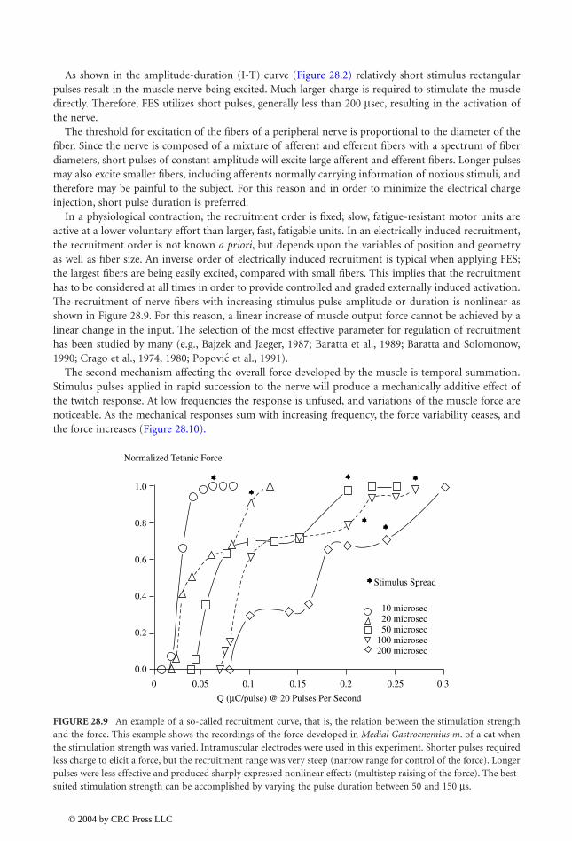
, but depends upon the variables of position and geometryas well as fiber size. An inverse order of electrically induced recruitment is typical when applying FES;the largest fibers are being easily excited, compared with small fibers. This implies that the recruitmenthas to be considered at all times in order to provide controlled and graded externally induced activation.The recruitment of nerve fibers with increasing stimulus pulse amplitude or duration is nonlinear asshown in Figure 28.9. For this reason, a linear increase of muscle output force cannot be achieved by alinear change in the input. The selection of the most effective parameter for regulation of recruitmenthas been studied by many (e.g., Bajzek and Jaeger, 1987; Baratta et al., 1989; Baratta and Solomonow,1990; Crago et al., 1974, 1980; et al., 1991).
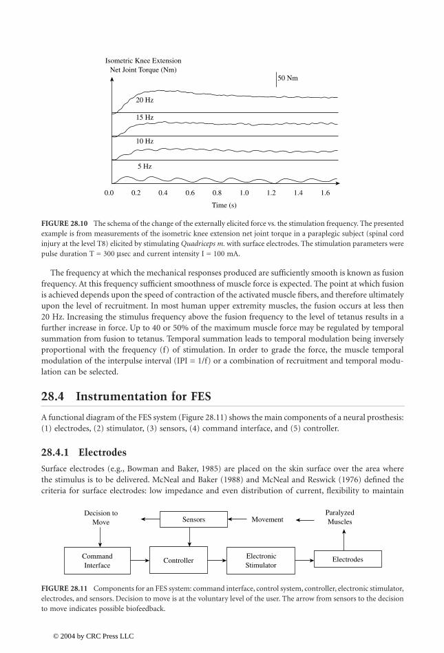
The second mechanism affecting the overall force developed by the muscle is temporal summation.Stimulus pulses applied in rapid succession to the nerve will produce a mechanically additive effect ofthe twitch response. At low frequencies the response is unfused, and variations of the muscle force arenoticeable. As the mechanical responses sum with increasing frequency, the force variability ceases, andthe force increases (Figure 28.10).
FIGURE 28.9
An example of a so-called recruitment curve, that is, the relation between the stimulation strengthand the force. This example shows the recordings of the force developed in
Medial Gastrocnemius m
. of a cat whenthe stimulation strength was varied. Intramuscular electrodes were used in this experiment. Shorter pulses requiredless charge to elicit a force, but the recruitment range was very steep (narrow range for control of the force). Longerpulses were less effective and produced sharply expressed nonlinear effects (multistep raising of the force). The best-suited stimulation strength can be accomplished by varying the pulse duration between 50 and 150
m
s.
Popovic
1.0
0.8
0.6
0.4
0.2
0.0
0 0.05
Q (µC/pulse) @ 20 Pulses Per Second
0.1 0.15 0.2 0.25 0.3
10 microsec20 microsec50 microsec
100 microsec200 microsec
Stimulus Spread
Normalized Tetanic Force
1140_bookreps.fm Page 12 Tuesday, July 15, 2003 9:47 AM
© 2004 by CRC Press LLC
Neural Prostheses for Movement Restoration
28
-13
The frequency at which the mechanical responses produced are sufficiently smooth is known as fusionfrequency. At this frequency sufficient smoothness of muscle force is expected. The point at which fusionis achieved depends upon the speed of contraction of the activated muscle fibers, and therefore ultimatelyupon the level of recruitment. In most human upper extremity muscles, the fusion occurs at less then20 Hz. Increasing the stimulus frequency above the fusion frequency to the level of tetanus results in afurther increase in force. Up to 40 or 50% of the maximum muscle force may be regulated by temporalsummation from fusion to tetanus. Temporal summation leads to temporal modulation being inverselyproportional with the frequency (f) of stimulation. In order to grade the force, the muscle temporalmodulation of the interpulse interval (IPI = 1/f) or a combination of recruitment and temporal modu-lation can be selected.
28.4 Instrumentation for FES
A functional diagram of the FES system (Figure 28.11) shows the main components of a neural prosthesis:(1) electrodes, (2) stimulator, (3) sensors, (4) command interface, and (5) controller.
28.4.1 Electrodes
Surface electrodes (e.g., Bowman and Baker, 1985) are placed on the skin surface over the area wherethe stimulus is to be delivered. McNeal and Baker (1988) and McNeal and Reswick (1976) defined thecriteria for surface electrodes: low impedance and even distribution of current, flexibility to maintain
FIGURE 28.10
The schema of the change of the externally elicited force vs
.
the stimulation frequency. The presentedexample is from measurements of the isometric knee extension net joint torque in a paraplegic subject (spinal cordinjury at the level T8) elicited by stimulating
Quadriceps m.
with surface electrodes. The stimulation parameters werepulse duration T = 300
m
sec and current intensity I = 100 mA.
FIGURE 28.11
Components for an FES system: command interface, control system, controller, electronic stimulator,electrodes, and sensors. Decision to move is at the voluntary level of the user. The arrow from sensors to the decisionto move indicates possible biofeedback.
0.0 0.2
5 Hz
10 Hz
15 Hz
20 Hz
0.4 0.6 0.8
Time (s)
Isometric Knee ExtensionNet Joint Torque (Nm)
50 Nm
1.0 1.2 1.4 1.6
Sensors MovementParalyzedMuscles
ControllerElectronicStimulator
CommandInterface
Decision toMove
Electrodes
1140_bookreps.fm Page 13 Tuesday, July 15, 2003 9:47 AM
© 2004 by CRC Press LLC

28
-14
Biomedical Technology and Devices Handbook
good skin contact, ease of application and removal, and suitable mounting for days without irritation ofthe skin. A surface electrode has three elements: the conductor, the interfacial layer, and the adhesive.The earliest electrodes used metal plates for the conductor, gel- or saline-saturated fabric for the interfaciallayer, and tape or circumferential bands for maintaining position. Substantial improvements of theseelectrodes have been directed toward resolving some of the problems, such as drying of the conductor,difficulties in application, and maintaining position and good electrical contact of the entire electrodesurface, especially on the skin surfaces with a large radius of curvature (back and abdomen). Usage ofconductive polymer and conductive adhesives proved to be effective for clinical and home usage. Surfaceelectrodes for most applications have a rather large surface area of 5 cm
2
or more (Figure 28.12).The stimulus parameters required for activation by using surface electrodes depend on the stimulus
waveform, the surface area, electrode materials, placement, skin impedance, and other factors. Typically,for the rectangular pulsatile waveform frequently used, threshold values are 30 mA or greater for a pulsewidth of 100 to 300
m
sec. Stimulus pulses shorter than the 50
m
sec cause a stronger, unpleasant sensation(pain), and thus are not used. The frequency of stimulation depends on the application but it is typicallybetween 16 and 50 pulses per second.
The primary limitation encountered with surface electrodes is that small muscles generally cannotbe selectively activated, and deep muscle cannot be activated without first exciting muscles that aremore superficial. Furthermore, fine gradation of force can be difficult because relative movementbetween the electrode and muscle will alter the stimulation-force relationship. Physical movement ofthe electrode can cause such movement, from length changes in the muscle induced by the contractionprocess, or from internal change in the nerve-electrode geometry during isometric contraction. Thepain is definitely a limiting factor in applying surface electrodes in subjects with preserved sensoryand diminished motor functions.
Subcutaneous (s.c.) electrodes can be divided into those in which the electrode is secured to themuscle exciting the motorneurons, and those that contact the nerve that contains the motoneurons.The advantages of s.c. electrodes vs. surface electrodes are better selectivity, repeatable excitation, andpermanent positioning. The sensation to the users is much more comfortable because the electrodes
FIGURE 28.12
An example of surface electrodes made as multilayer structure. These electrodes can be used in thesame subject for several times during a period of about 2 weeks. The electrodes can be moisturized for better contactif they start drying up; this will decrease the impedance (capacitance). The bottom (skin side) layer is a polymerwith strong adhesive properties that sticks to the skin, the middle is a conductive layer (metal) connected with thelead, and the top (external) layer is the isolating material. The construction provides an interface with the evenlydistributed current density over the surface of the electrode. The electrodes are flexible and manufactures in differentsizes (e.g., small circular electrodes D = 2.5 cm, small square electrodes a = 4 cm, big rectangular electrodes a
¥
b= 8 cm
¥
12 cm).
1140_bookreps.fm Page 14 Tuesday, July 15, 2003 9:47 AM
© 2004 by CRC Press LLC
Neural Prostheses for Movement Restoration
28
-15
are placed away from the pain receptors, and the current amplitude is much lower. The potentialdisadvantage of implanted electrode is the damage that can result from improper design and implan-tation (e.g., irreversible deleterious effects to the neural tissue, physical failure of an electrode requiringan invasive revision procedure).
The mechanisms of failure of s.c. electrodes may be separated into three categories: physiological,biological, or physical (Mortimer, 1981; Scheiner et al., 1990). The biological failures include thosemechanically induced at surgical installation, excess encapsulation, infection or rejection, and thoseinduced with stimulation (Mortimer, 1981). The physical failures are those of the conductor, such aselectrochemical degradation or mechanical failures (breakage), and of the insulator. Categorization ofelectrode failure requires, if possible, identification of the failure mechanisms to at least this level (Scheineret al., 1990; Smith et al., 1994).
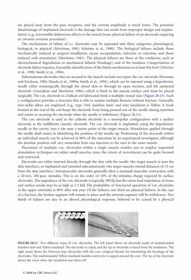
Subcutaneous electrodes that are secured to the muscle include two types: the i.m. electrode (Bowmanand Erickson, 1985; Handa et al., 1989a; Smith et al., 1994), which can be injected using a hypodermicneedle either nonsurgically through the closed skin or through an open incision, and the epimysialelectrode (Grandjean and Mortimer, 1986), which is fixed to the muscle surface and must be placedsurgically. The i.m. electrode is a helical coil fabricated from a multiple-strand wire (Figure 28.13). Sucha configuration provides a structure that is able to sustain multiple flexions without fracture. Generally,non-noble alloys are employed (e.g., type 316L stainless steel) and wire insulation is Teflon. A hookformed at the end of the coil keeps the electrode from being pressed out of the needle during insertionand assists in securing the electrode when the needle is withdrawn (Figure 28.13).
The i.m. electrode is used as the cathode electrode in a monopolar configuration with a surfaceelectrode as the indifferent (anode) electrode. The i.m. electrode is implanted, using the hypodermicneedle as the carrier, into a site near a motor point of the target muscle. Stimulation applied throughthe needle shaft assists in identifying the position of the needle tip. Positioning of the electrode withinan individual muscle can be achieved in 80% of the injections by an experienced investigator, althoughthe absolute position will vary somewhat from one injection to the next in the same muscle.
Placement of multiple i.m. electrodes within a single muscle enables one to employ sequentialstimulation techniques on rather small muscles, since the extent of recruitment can be quite focusedand restricted.
Electrodes are either inserted directly through the skin with the needle (the target muscle is near theskin interface), or implanted and tunneled subcutaneously (the target muscles extend distances of 15 cmfrom the skin interface). Intramuscular electrodes generally elicit a maximal muscular contraction witha 20-mA, 200-
m
sec stimulus. This is on the order of 10% of the stimulus charge required by surfaceelectrodes. The impedance of the i.m. electrode is typically 300
W
, but the entire load impedance of tissueand surface anode may be as high as 1.5 k
W
. The probability of functional operation of i.m. electrodesin the upper extremity is 80% after one year. Of the failures, one third are physical failures. In the caseof a fracture, the broken segment will remain in place and the external segment will be withdrawn. Twothirds of failures are due to an altered physiological response, believed to be caused by a physical
FIGURE 28.13
Two different types of i.m. electrodes. The left panel shows an electrode made of multistrandedstainless steel and Teflon insulated. The electrode is coiled, and the tip of electrode is bared from the insulation. Theright panel shows the Peterson-type electrodes with the core (surgical thread) for minimizing the breakage of theelectrodes. The multistranded Teflon-insulated stainless steel wire is rapped around the core. The tip of the electrodeshows the wires when the insulation was taken off.
1140_bookreps.fm Page 15 Tuesday, July 15, 2003 9:47 AM
© 2004 by CRC Press LLC

28
-16
Biomedical Technology and Devices Handbook
displacement of the electrode, and present modifications on electrode design are under way to correctboth problems.
The primary disadvantage of percutaneous electrodes is the maintenance of the skin interface, yetreports show that only few infections occurred in implantation of over 2000 electrodes, someimplanted for more than 5 years (Peckham, 1988). Granulomas at the skin interface are infrequent,but they are treated with local cauterization. The advantage of percutaneous (i.m.) electrodes oversurface electrodes is that they provide a means of eliciting focused, repeatable responses over timewith a nonsurgical technique.
The epimysial electrode (e.g., Grandjean and Mortimer, 1986) is a disk-shaped metal with a reinforcedpolymer for shielding the surface away from the muscle and for suturing to the muscle (Figure 28.14).The electrode is surgically placed on the muscle near the motor point. The conductive surface of the diskis 3 mm in diameter. In contrast to the i.m. electrode where the placement is surgical and small size isnot so essential, the lead may have a more mechanical redundancy than the i.m. lead.
The impedance and physiologic characteristics of stimulation over this electrode are also similar tothe i.m. electrode. That is, the recruitment is nonlinear with either pulse-amplitude or pulse-widthmodulation and may be approximated by piecewise linear segments. The recruitment may also be lengthdependent, meaning that the force output changes with muscle length due to changes in the electrodeto nerve coupling. This is in addition to the length-tension properties of the muscle.
Another type of surgically placed electrodes are nerve electrodes. Nerve electrodes have the potentialfor producing the most desired physiological response (Sweeney and Mortimer, 1986; Naples et al., 1988;Rutten et al., 1991; Sweeney et al., 1990; Loeb and Peck, 1996). The electrode must be designed with anappreciation for the sensitivity of the nerve to mechanical trauma, manifest by swelling, its longitudinalmobility during muscle movement, and the necessity of maintaining a constant orientation between thenerve fibers and the electrode.
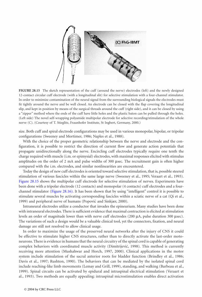
The nerve electrodes are characterized by their placement relative to the nerve: encircling or intraneu-ral. Cuff electrodes encircle the nerve; they have either a tube or a spiral configuration (Figure 28.15).The latter is a loose, open helix, which is wrapped around the nerve in a monopolar configuration. Cuffelectrodes come in a variety of configurations; they all have a longitudinal opening to allow installationon the nerve without damaging it. The cuff is formed of a polymer (usually silicone rubber or recentlypolyamide), sometimes reinforced with Dacron. The electrodes within the cuff are made out of metal,usually being circumferential around the inner surface of the cuff. A self-wrapping cuff (Naples et al.,1988) uses the same materials, yet it is self-sized, thus eliminating the problem of selecting the appropriate
FIGURE 28.14
An example of the epimysial electrode. The electrode is made out of platinum (disk with the diameterof 0.5 cm) that is welded to the stainless steel wire. The stainless steel wire is Teflon insulated and pulled through asilastic tube filled with silastic, thereby eliminating air bubbles in the tube. The electrode is surgically positioned atthe surface of the muscle and sutured to the fascia by using the Dacron-reinforced silastic material surrounding themetal contact.
1140_bookreps.fm Page 16 Tuesday, July 15, 2003 9:47 AM
© 2004 by CRC Press LLC
Neural Prostheses for Movement Restoration
28
-17
size. Both cuff and spiral electrode configurations may be used in various monopolar, bipolar, or tripolarconfigurations (Sweeney and Mortimer, 1986; Naples et al., 1988).
With the choice of the proper geometric relationship between the nerve and electrode and the con-figuration, it is possible to restrict the direction of current flow and generate action potentials thatpropagate unidirectionally along the nerve. Encircling cuff electrodes typically require one tenth thecharge required with muscle (i.m. or epimysial) electrodes, with maximal responses elicited with stimulusamplitudes on the order of 2 mA and pulse widths of 300
m
sec. The recruitment gain is often highercompared with the i.m. electrodes, and similar nonlinearities are encountered.
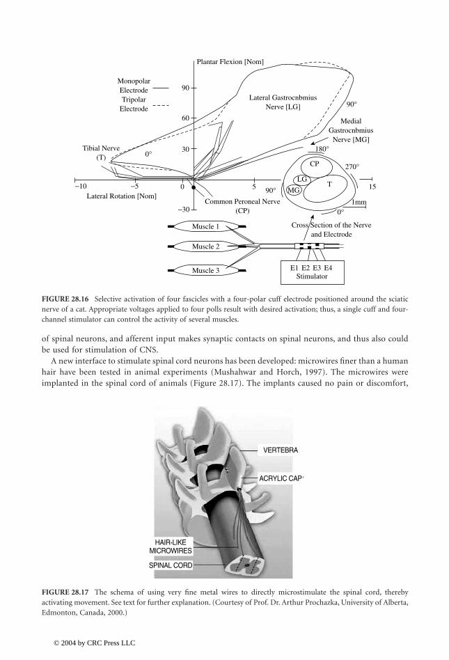
Today the design of new cuff electrodes is oriented toward selective stimulation, that is, possible steeredstimulation of various fascicles within the same large nerve (Sweeney et al., 1995; Veraart et al., 1993).Figure 28.15 shows the multipolar cuff electrode for selective stimulation of nerves. Experiments havebeen done with a tripolar electrode (12 contacts) and monopolar (4 contacts) cuff electrodes and a four-channel stimulator (Figure 28.16). It has been shown that by using “intelligent” control it is possible tostimulate several muscles by activating corresponding fascicles within a sciatic nerve of a cat (Qi et al.,1999) and peripheral nerve of humans ( and Sinkjær, 2000).
Intraneural electrodes utilize a conductor that invades the epineurium. Many studies have been donewith intraneural electrodes. There is sufficient evidence that maximal contraction is elicited at stimulationlevels an order of magnitude lower than with nerve cuff electrodes (200 mA, pulse duration 300 msec).The variations of such a design would be a valuable clinical tool, yet the connectors, fixation, and neuraldamage are still not resolved to allow clinical usage.
In order to maximize the usage of the preserved neural networks after the injury of CNS it couldbe effective to stimulate higher CNS structures, rather than to directly activate the last-order moto-neurons. There is evidence in humans that the neural circuitry of the spinal cord is capable of generatingcomplex behaviors with coordinated muscle activity ( , 1998). This method is currentlyreceiving more attention (Mushahwar and Horch, 1997, 2000). Clinical applications in the motorsystem include stimulation of the sacral anterior roots for bladder function (Brindley et al., 1986;Davis et al., 1997; Rushton, 1990). The behaviors that can be mediated by the isolated spinal cordinclude reaching-like limb movements (Lemay and Grill, 1999), standing, and walking (Barbeau et al.,1999). Spinal circuits can be activated by epidural and intraspinal electrical stimulation (Veraart etal., 1993). Two methods are equally appealing: intraspinal microstimulation enables direct activation
FIGURE 28.15 The sketch representation of the cuff (around the nerve) electrodes (left) and the newly designed12-contact circular cuff electrode (with a longitudinal slit) for selective stimulation with a four-channel stimulator.In order to minimize contamination of the neural signal from the surrounding biological signals the electrodes mustfit tightly around the nerve and be well closed. An electrode can be closed with the flap covering the longitudinalslip, and kept in position by means of the surgical threads around the cuff (right side), and it can be closed by usinga “zipper” method where the ends of the cuff have little holes and the plastic baton can be pulled through the holes.(Left side) The novel self-wrapping polyamide multipolar electrode for selective recording/stimulation of the wholenerve (C). (Courtesy of T. Stieglitz, Fraunhofer Institute, St Ingbert, Germany, 2000.)
Popovic
Dimitrijevic
1140_bookreps.fm Page 17 Tuesday, July 15, 2003 9:47 AM
© 2004 by CRC Press LLC
28-18 Biomedical Technology and Devices Handbook
of spinal neurons, and afferent input makes synaptic contacts on spinal neurons, and thus also couldbe used for stimulation of CNS.
A new interface to stimulate spinal cord neurons has been developed: microwires finer than a humanhair have been tested in animal experiments (Mushahwar and Horch, 1997). The microwires wereimplanted in the spinal cord of animals (Figure 28.17). The implants caused no pain or discomfort,
FIGURE 28.16 Selective activation of four fascicles with a four-polar cuff electrode positioned around the sciaticnerve of a cat. Appropriate voltages applied to four polls result with desired activation; thus, a single cuff and four-channel stimulator can control the activity of several muscles.
FIGURE 28.17 The schema of using very fine metal wires to directly microstimulate the spinal cord, therebyactivating movement. See text for further explanation. (Courtesy of Prof. Dr. Arthur Prochazka, University of Alberta,Edmonton, Canada, 2000.)
Lateral Rotation [Nom]
Tibial Nerve(T)
MonopolarElectrodeTripolar
Electrode
Plantar Flexion [Nom]
Lateral GastrocnbmiusNerve [LG]
MedialGastrocnbmius
Nerve [MG]
Common Peroneal Nerve(CP)
−10 −5 0 5 90°
0°
0°
1mm−30
30
60
90
90°
270°
180°
15
Cross Section of the Nerveand Electrode
T
CP
LG
MG
Muscle 1
Muscle 2
Muscle 3 E1 E2 E3 E4Stimulator
HAIR-LIKEMICROWIRES
SPINAL CORD
ACRYLIC CAP
VERTEBRA
1140_bookreps.fm Page 18 Tuesday, July 15, 2003 9:47 AM
© 2004 by CRC Press LLC
Neural Prostheses for Movement Restoration 28-19
and the motor activity remained normal, indicating that the wires had not damaged the spinal cord.When trains of electrical micropulses were delivered through the microwires, the stimuli were notperceived, yet strong coordinated limb movements were produced, sufficient to support body weight.This indicates that spinal cord microstimulation could generate useful movement in people withparaplegia or tetraplegia.
28.4.2 Electronic Stimulators
An electronic stimulator for FES application has to be a self-contained device with a low power con-sumption, small, light, and must have the simplest possible user interface (Bijak et al., 1999; Brindley etal., 1978; Buckett et al., 1988; Donaldson, 1986; et al., 1994; James et al., 1991; Minzly et al., 1993;Smith et al., 1987; Thrope et al., 1985; Bogataj et al., 1989). The stimulator should be programmable,and the programming should be done wireless, although using wires is acceptable. The stimulator needsa set-up mode; mode of programming when communicating with the host computer. Once the pro-gramming is finished, the stimulator should be turned to the autonomous mode.
An electronic stimulator must have the following elements: power source or communication link toa remote unit that delivers energy for operation, DC/DC converter, output stage that generates current-regulated or voltage-regulated pulses, and the controller that defines the shape, intensity, and frequencyof pulses ( et al., 1994). The DC/DC is a system that generates the needed high voltage for stimulation.In some cases the required voltage must be as high as 300 V, yet in others it is within 10 V. The outputstages are parts that secure that the pulse applied will be effective, yet not harmful.
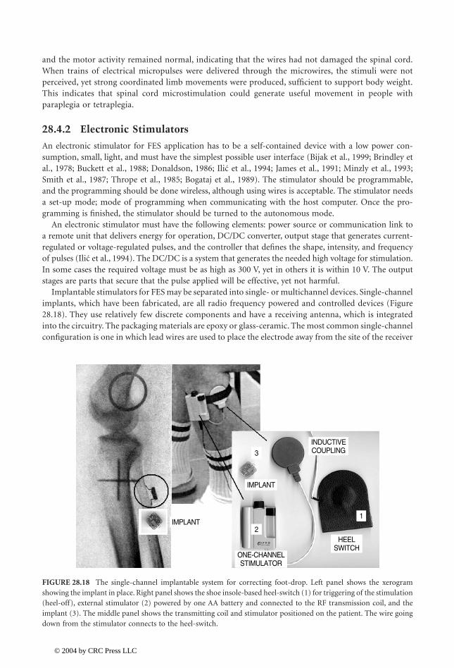
Implantable stimulators for FES may be separated into single- or multichannel devices. Single-channelimplants, which have been fabricated, are all radio frequency powered and controlled devices (Figure28.18). They use relatively few discrete components and have a receiving antenna, which is integratedinto the circuitry. The packaging materials are epoxy or glass-ceramic. The most common single-channelconfiguration is one in which lead wires are used to place the electrode away from the site of the receiver
FIGURE 28.18 The single-channel implantable system for correcting foot-drop. Left panel shows the xerogramshowing the implant in place. Right panel shows the shoe insole-based heel-switch (1) for triggering of the stimulation(heel-off), external stimulator (2) powered by one AA battery and connected to the RF transmission coil, and theimplant (3). The middle panel shows the transmitting coil and stimulator positioned on the patient. The wire goingdown from the stimulator connects to the heel-switch.
Ilic
Ilic
ONE-CHANNELSTIMULATOR
HEELSWITCH
INDUCTIVECOUPLING
IMPLANT
IMPLANT1
3
2
1140_bookreps.fm Page 19 Tuesday, July 15, 2003 9:47 AM
© 2004 by CRC Press LLC
28-20 Biomedical Technology and Devices Handbook
unit. Avery and Medtronics employed this design for neuromuscular applications in commerciallyavailable devices many years ago.
Alternatively, the electrodes may be an integral part of the packaging of the circuitry, allowing theentire device to be placed adjacent to the nerve such as it is in the Ljubljana-designed implantable foot-drop system (Strojnik et al., 1987).
Two alternative schemes have been considered for multimuscle excitation. It is possible, in principle,to use several one-channel units that are controlled from one controller (Cameron et al., 1997; Strojniket al., 1987), or to use a single implantable stimulator that will connect with multiple electrodes (Holleet al., 1984; Thoma et al., 1978; Rushton, 1990; Strojnik et al., 1990; Smith et al., 1996; Davis et al., 1997).
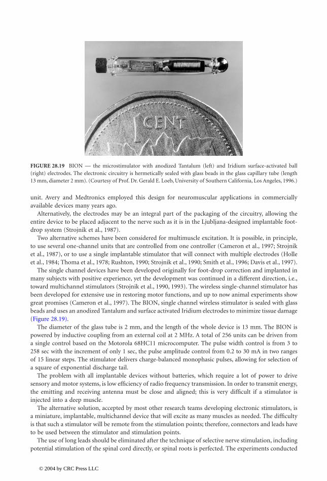
The single channel devices have been developed originally for foot-drop correction and implanted inmany subjects with positive experience, yet the development was continued in a different direction, i.e.,toward multichannel stimulators (Strojnik et al., 1990, 1993). The wireless single-channel stimulator hasbeen developed for extensive use in restoring motor functions, and up to now animal experiments showgreat promises (Cameron et al., 1997). The BION, single channel wireless stimulator is sealed with glassbeads and uses an anodized Tantalum and surface activated Iridium electrodes to minimize tissue damage(Figure 28.19).
The diameter of the glass tube is 2 mm, and the length of the whole device is 13 mm. The BION ispowered by inductive coupling from an external coil at 2 MHz. A total of 256 units can be driven froma single control based on the Motorola 68HC11 microcomputer. The pulse width control is from 3 to258 sec with the increment of only 1 sec, the pulse amplitude control from 0.2 to 30 mA in two rangesof 15 linear steps. The stimulator delivers charge-balanced monophasic pulses, allowing for selection ofa square of exponential discharge tail.
The problem with all implantable devices without batteries, which require a lot of power to drivesensory and motor systems, is low efficiency of radio frequency transmission. In order to transmit energy,the emitting and receiving antenna must be close and aligned; this is very difficult if a stimulator isinjected into a deep muscle.
The alternative solution, accepted by most other research teams developing electronic stimulators, isa miniature, implantable, multichannel device that will excite as many muscles as needed. The difficultyis that such a stimulator will be remote from the stimulation points; therefore, connectors and leads haveto be used between the stimulator and stimulation points.
The use of long leads should be eliminated after the technique of selective nerve stimulation, includingpotential stimulation of the spinal cord directly, or spinal roots is perfected. The experiments conducted
FIGURE 28.19 BION — the microstimulator with anodized Tantalum (left) and Iridium surface-activated ball(right) electrodes. The electronic circuitry is hermetically sealed with glass beads in the glass capillary tube (length13 mm, diameter 2 mm). (Courtesy of Prof. Dr. Gerald E. Loeb, University of Southern California, Los Angeles, 1996.)
1140_bookreps.fm Page 20 Tuesday, July 15, 2003 9:47 AM
© 2004 by CRC Press LLC

Neural Prostheses for Movement Restoration 28-21
at Aalborg University with the two-channel fully implanted RF-driven stimulators (Haugland et al., 1999)integrated in the cuff electrode (Figure 28.20) suggest that this is a viable technique. Selective activationof different muscle groups has been achieved in a sitting and walking subject.
The stimulation-telemetry system described by Smith et al. (1998) is an example of state-of-the-arttechnology (Figure 28.29). The device can be configured with the following functions: (1) up to 32independent channels of stimulation for activation of muscles (or sensory feedback), with independentcontrol of stimulus pulse interval, pulse duration, pulse amplitude, interphase delay (for biphasic stimuluswaveform), and recharge phase duration (for biphasic stimulus waveform); (2) up to eight independenttelemetry channels for sensors, with independent control of sampling rate and pulse powering parametersof the sensor (power amplitude and duration); (3) up to eight independent telemetry channels forprocessed (rectified and integrated) signals measured from muscles or nerves (EMG or ENG), withindependent control of the sampling rate and provisions for stimulus artifact blanking and processingcontrol; (4) up to eight independent telemetry channels for unprocessed MES channels, with independentcontrol of sampling rate; and (5) up to eight independent telemetry channels for system functions,providing control or sampling of internal system parameters, such as internal voltage levels.
Due to overall timing constraints, implant circuit size, implant capsule size, number of lead wires,circuit and sensor power consumption, and external control and processing requirements, it is notpractical to realize a single device having the maximal capabilities outlined above. However, the intentof the stimulator-telemeter system is to provide the means of realizing an optimal implantable devicehaving all the necessary circuitry and packaging to meet the anticipated clinical applications, withoutrequiring design or engineering effort beyond that of fabricating the device itself. For example, a basicupper extremity application would require, minimally, eight channels of stimulation for providingpalmar and lateral grasp and sensory feedback, along with one joint angle transducer as a commandcontrol source.
The stimulation-telemetry implant device comprises an electronic circuit that is hermetically sealedin a titanium capsule with feedthroughs. A single internal radio frequency (RF) coil provides transcuta-neous reception of power and bidirectional communication. The lead wires connected to the feed-throughholes extend to the stimulating electrodes, to the implanted sensors, or to the recording electrodes. Thelater two connections are used as control input. The circuit capsule, coil, and lead wire exits are con-formably coated in epoxy and silicone elastomer to provide physical support for the feedthroughs andRF coil, and stress relief to the leads making it suitable for long-term implantation.
The functional elements required to realize the system include the following: (1) an RF receiver forrecovering power and functional commands transmitted from an external control unit; (2) control logic
FIGURE 28.20 Two types of fully implantable cuff-electrode-based stimulators under development. Stimulatorsinclude the multipolar neural interface and electronic circuitry for energy and control signals communication.(Courtesy of Dr. Morten Haugland, Aalborg University, Denmark, 2002.)
1140_bookreps.fm Page 21 Tuesday, July 15, 2003 9:47 AM
© 2004 by CRC Press LLC
28-22 Biomedical Technology and Devices Handbook
circuitry to interpret the recovered signals, execute the command function, and to supervise functionalcircuit blocks; (3) multichannel stimulation circuitry for generating the stimulus pulses that are sent tothe stimulating electrodes; (4) multichannel signal conditioning circuitry which provides amplification,filtering, and processing for the signals to be acquired (MES and sensor signals); (5) data acquisitioncircuitry for sampling and digitizing these signals; (6) modulation circuitry for telemetring the acquireddata through the RF link; (7) power regulation and switching circuitry for selectively powering theincluded functional blocks of the circuitry, as needed, to minimize power consumption of the device;and (8) system control circuitry to allow interrogation or configuration of the operation of the device.
28.4.3 Sensors
Sensors for NP applications should provide to both the system and the user information regarding theconditions of the neural prosthesis. In some cases, it is not obvious that the user does need instantinformation (e.g., if automatic execution follows the desired trajectory), yet if anything unexpected ishappening, the sensory warning may prevent catastrophic consequences. Sensors are needed in FES systemsfor the command interface (e.g., activating the neural prosthesis, changing the mode of operation).
The sensory system to be used should provide information of various kinds, such as the contact forceor pressure over the area of contact (grasping, standing, and walking), the position of the joints (pre-hension, reaching, standing, and walking), and perhaps the activity of the muscle. The dynamic range,resolution, and frequency response of sensors must be determined upon the application. For example,force sensors for walking and standing must withstand several times body weight under dynamic loadingand joint position sensors must allow unrestrained movement over the entire range of motion of thejoint (Figure 28.21).
The constraints imposed on the sensors for FES systems are significant; they must be cosmeticallyacceptable and easy to mount, they should be self-contained, have low power consumption, and mustprovide adequate information. In most available FES systems sensors are placed externally. The sensorpositioned at the surface of the body is not a suitable solution for many situations (e.g., an external-forcesensor on the digits of the hand requires donning and needs a cable to communicate with the controlbox, and it should work in variable temperature conditions and hazardous environment). The alternativeis to use implanted sensors. They have to meet the same performance specifications while functioningin a more hostile environment. These sensors should communicate with the remote control box, and thedevice must be powered via radio frequency (RF) link. The ultimate solution is to use available sensorin the organism; to record from nerves and muscles and process the information in a real-time usefulsignal. This solution requires the ability to interface without the nerves and interpret the signals they aresupplying to the central nervous system.
28.4.3.1 Artificial Sensors for Neural Prostheses
In order to control the position of the extremity, it is of interest to know the joint angles and joint angularvelocities, and if in contact with the environment, the contact forces. The most commonly used sensorsfor measuring joint angles are potentiometers. However, joint angle can be effectively measured withoptocouplers, optical fibers, strain gages, Hall-effect transducers, and magneto-transistors as well as manyother transducers.
The field-effect transistor (FET) is a micro-miniature electronic device in which the current amplifi-cation depends on the applied voltages. In principle, the FET transistor has three zones, source, gate,and drain; the width of the gate determines the gain of the transistor. The arrays of FET devices mountedon specially designed support rely on the change of the gate width provoked by force. This device is ableto measure microstrains and displacements in parallel with measuring of finite displacements. A singleFET could record small displacements; multiple devices built in a single semiconductor support areconvenient for measuring bigger displacements.
The piezoresistive sensors are very frequently used in recording of displacements, forces, and pressures.The most frequently used sensors are strain gauges, yet they are often unsuitable for neuroprosthetics
1140_bookreps.fm Page 22 Tuesday, July 15, 2003 9:47 AM
© 2004 by CRC Press LLC

Neural Prostheses for Movement Restoration 28-23
because of the size, power consumption, and temperature variability. The use of polymer elastomer iseffective for recordings of the forces and pressures. The elastomers can be stretched or compressedappreciably, but they return to their original shapes after the stress is removed. The elastomers are madeconductive by impregnating them with metal powders or carbon black. The electrical conductivity ofelastomers using metal fillers is good, but elastomers exhibit nonuniformly large hysteresis, and poortensile and compression properties. Moreover, it was found that the hardness of the rubber couldn’t bemade independent of the metallic loading for a given conductivity (Webster, 1988). Maalej and Webster(1988) have investigated the Interlink manufactured Force Sensing Resistors (FSRs) based on elastomermaterial. With the instrumentation capable of dealing with the hysteresis and nonlinearity, the sensorwas suggested as a valuable asset for neuroprosthetics.
It is possible to use piezoelectric sensors in NP. The high level of piezoelectricity was obtained by poly-vinylidene fluoride-based polymers. Polyvinylidene fluoride (PVF2) became a popular sensor (Dario etal., 1983). PVF2 films mechanically appear the same as a thin sheet of plastic. These films are flexibleand durable. Their flexibility allows them to be manufactured in large thin sheets or complex shapes,
FIGURE 28.21 Several types of sensors used in various neural prostheses. (A) Hall-effect-based position transducerfor volitional generation of commands; (B) wrist position sensor for measuring wrist movement; (C) implantableversion of the Hall-effect transducer for measuring wrist movement; (D) EMG electrodes and preamplifier for EMGfeedback; (E) force sensing resistors built into an insole for measuring the ground reaction forces and pressures; (F)flexible goniometers (Penny and Giles, Blackwood, U.K.) for measuring joint angles. The later three are used insampled data feedback and closed loop control schema.
WRISTTRANSDUCER
SHOULDERPOSITIONAL
TRANSDUCER
HALL EFFECTTRANSDUCER
FORCESENSING
RESISTORS
FLEXIBLEGONIOMETERS
EMGAMPLIFIERS
A
D
E
C
F
B
1140_bookreps.fm Page 23 Tuesday, July 15, 2003 9:47 AM
© 2004 by CRC Press LLC
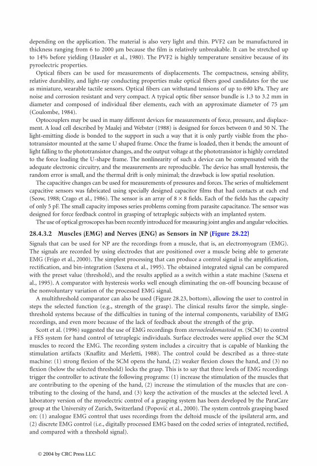
28-24 Biomedical Technology and Devices Handbook
depending on the application. The material is also very light and thin. PVF2 can be manufactured inthickness ranging from 6 to 2000 µm because the film is relatively unbreakable. It can be stretched upto 14% before yielding (Hausler et al., 1980). The PVF2 is highly temperature sensitive because of itspyroelectric properties.
Optical fibers can be used for measurements of displacements. The compactness, sensing ability,relative durability, and light-ray conducting properties make optical fibers good candidates for the useas miniature, wearable tactile sensors. Optical fibers can withstand tensions of up to 690 kPa. They arenoise and corrosion resistant and very compact. A typical optic fiber sensor bundle is 1.3 to 3.2 mm indiameter and composed of individual fiber elements, each with an approximate diameter of 75 µm(Coulombe, 1984).
Optocouplers may be used in many different devices for measurements of force, pressure, and displace-ment. A load cell described by Maalej and Webster (1988) is designed for forces between 0 and 50 N. Thelight-emitting diode is bonded to the support in such a way that it is only partly visible from the pho-totransistor mounted at the same U shaped frame. Once the frame is loaded, then it bends; the amount oflight falling to the phototransistor changes, and the output voltage at the phototransistor is highly correlatedto the force loading the U-shape frame. The nonlinearity of such a device can be compensated with theadequate electronic circuitry, and the measurements are reproducible. The device has small hysteresis, therandom error is small, and the thermal drift is only minimal; the drawback is low spatial resolution.
The capacitive changes can be used for measurements of pressures and forces. The series of multielementcapacitive sensors was fabricated using specially designed capacitor films that had contacts at each end(Seow, 1988; Crago et al., 1986). The sensor is an array of 8 ¥ 8 fields. Each of the fields has the capacityof only 5 pF. The small capacity imposes series problems coming from parasite capacitance. The sensor wasdesigned for force feedback control in grasping of tetraplegic subjects with an implanted system.
The use of optical gyroscopes has been recently introduced for measuring joint angles and angular velocities.
28.4.3.2 Muscles (EMG) and Nerves (ENG) as Sensors in NP (Figure 28.22)
Signals that can be used for NP are the recordings from a muscle, that is, an electromyogram (EMG).The signals are recorded by using electrodes that are positioned over a muscle being able to generateEMG (Frigo et al., 2000). The simplest processing that can produce a control signal is the amplification,rectification, and bin-integration (Saxena et al., 1995). The obtained integrated signal can be comparedwith the preset value (threshold), and the results applied as a switch within a state machine (Saxena etal., 1995). A comparator with hysteresis works well enough eliminating the on-off bouncing because ofthe nonvoluntary variation of the processed EMG signal.
A multithreshold comparator can also be used (Figure 28.23, bottom), allowing the user to control insteps the selected function (e.g., strength of the grasp). The clinical results favor the simple, single-threshold systems because of the difficulties in tuning of the internal components, variability of EMGrecordings, and even more because of the lack of feedback about the strength of the grip.
Scott et al. (1996) suggested the use of EMG recordings from sternocleidomastoid m. (SCM) to controla FES system for hand control of tetraplegic individuals. Surface electrodes were applied over the SCMmuscles to record the EMG. The recording system includes a circuitry that is capable of blanking thestimulation artifacts (Knaflitz and Merletti, 1988). The control could be described as a three-statemachine: (1) strong flexion of the SCM opens the hand, (2) weaker flexion closes the hand, and (3) noflexion (below the selected threshold) locks the grasp. This is to say that three levels of EMG recordingstrigger the controller to activate the following programs: (1) increase the stimulation of the muscles thatare contributing to the opening of the hand, (2) increase the stimulation of the muscles that are con-tributing to the closing of the hand, and (3) keep the activation of the muscles at the selected level. Alaboratory version of the myoelectric control of a grasping system has been developed by the ParaCaregroup at the University of Zurich, Switzerland ( et al., 2000). The system controls grasping basedon: (1) analogue EMG control that uses recordings from the deltoid muscle of the ipsilateral arm, and(2) discrete EMG control (i.e., digitally processed EMG based on the coded series of integrated, rectified,and compared with a threshold signal).
Popovic
1140_bookreps.fm Page 24 Tuesday, July 15, 2003 9:47 AM
© 2004 by CRC Press LLC
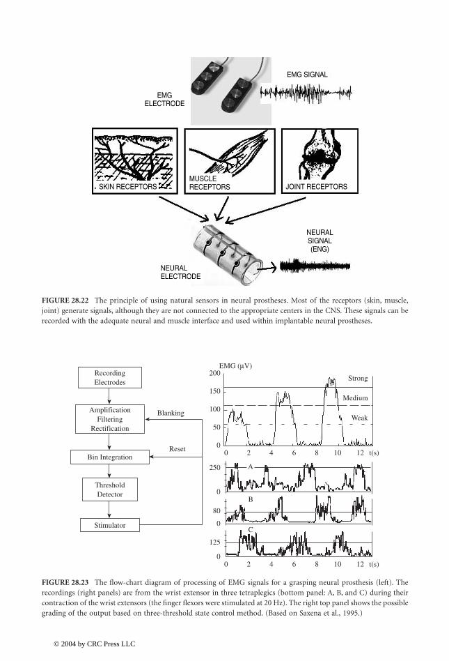
Neural Prostheses for Movement Restoration 28-25
FIGURE 28.22 The principle of using natural sensors in neural prostheses. Most of the receptors (skin, muscle,joint) generate signals, although they are not connected to the appropriate centers in the CNS. These signals can berecorded with the adequate neural and muscle interface and used within implantable neural prostheses.
FIGURE 28.23 The flow-chart diagram of processing of EMG signals for a grasping neural prosthesis (left). Therecordings (right panels) are from the wrist extensor in three tetraplegics (bottom panel: A, B, and C) during theircontraction of the wrist extensors (the finger flexors were stimulated at 20 Hz). The right top panel shows the possiblegrading of the output based on three-threshold state control method. (Based on Saxena et al., 1995.)
EMG SIGNAL
SKIN RECEPTORS JOINT RECEPTORS
EMGELECTRODE
NEURALSIGNAL(ENG)
MUSCLERECEPTORS
NEURALELECTRODE
Strong
Medium
Weak
EMG (µV)
00
250
0
80
0
0
125
50
100
150
200
2
A
B
C
4 6 8 10 12 t(s)
0 2 4 6 8 10 12 t(s)
RecordingElectrodes
ThresholdDetector
Stimulator
AmplificationFiltering
Rectification
Blanking
ResetBin Integration
1140_bookreps.fm Page 25 Tuesday, July 15, 2003 9:47 AM
© 2004 by CRC Press LLC
28-26 Biomedical Technology and Devices Handbook
It is possible to stimulate the same muscle that is used for control (Vossius et al., 1987). The aim ofthis method is to enhance the contraction of weak muscles. Sennels et al. (1997) and Thorsen et al. (1998,1999) have further developed this method, and some therapeutic application of electrical stimulationbenefit greatly (Francisco et al., 1998; Glanz et al., 1996).
Hart et al. (1998) used the EMG signals from three surface electrodes (bipolar recordings) placed overthe wrist extensor muscles to control the grasping NP. The proportional signals were determined basedupon the amplitude of the EMG recordings. It was necessary to use a blanking circuit to minimizestimulation artifacts. The same group developed very efficient processing techniques: adaptive timeconstant filter and adaptive step size (slow rate limiting) filter.
One of the common problems in the recording of the activity from muscles is the stimulation artifact.As described above, the way around this problem is to apply the circuitry that will blank the responsefor a period that is longer than the stimulation artifact. However, the stimulation contaminates the naturalsignals even at the muscle that is remote from the stimulation. The blanking circuitry is sufficient toeliminate the effects that could prevent recording and signal processing, yet additional filtering canimprove the canceling of the noise imposed by stimulation. One possible method is to estimate theartifact waveform from the subthreshold stimulation and subtract it from the sub-threshold stimulationresponse (McGill et al., 1982). Adaptive noise canceling (ANC) can be much more effectively achievedby means of an artificial neural network.
Electroneurogram (ENG) obtained from a cuff electrode (Hoffer and Loeb, 1980; Stein et al.,1975; Hoffer et al., 1995; Hoffer, 1988) is a viable signal for NP (Haugland and Sinkjær, 1995;Upshaw and Sinkjær, 1998; Haugland et al., 1999; Inmann, 2001). In the current implants at AalborgUniversity, Denmark a telemetric amplifier system that amplifies the ENG recorded from a tripolarnerve cuff electrode and transmits it from the implanted amplifier through the skin to an externalcontrol unit was demonstrated to work good enough in both walking and grasping NP. The outputis raw ENG, bandpass filtered from 800 Hz to 8000 Hz. The implant is powered by radiofrequencyinduction and will operate for a coil-to-coil separation up to 30 mm. Input-referred noise is notmore than 1 mV (r.m.s.). The device is small enough to be implanted in the extremities of humanadults. The method used for artifact suppression in nerve cuff electrode recordings is intimatelyrelated to the method for extraction of the envelope of the signal as described above for the EMG(Haugland and Hoffer, 1994a, 1994b) and is essentially based on rectification followed by theintegration of the signal during noise-free periods (bin-integration). Initially, the signal from theamplifier is high-pass filtered to remove the remaining EMG and noise contamination of the nervesignal, which is still present even after passing the filter in the amplifier. The signal is then rectifiedand bin-integrated (Figure 28.24).
An early example of using EMG and ENG for NP in animal demonstrated the feasibility of thisapproach ( et al., 1993). Several cats have been implanted for up to 3.5 years, and therecordings have been stable and reliable. The recordings have been processed with a portable, battery-powered device ( et al., 1994), which provided amplification, filtering, and BIN integration;thus real-time use of natural sensors for control was facilitated. Figure 28.25 (bottom panel) shows10 sec of the processed recordings from nerves and muscles in a walking cat. The top panel (Figure28.25) shows the original recordings from only one stride (indicated with the arrow in the bottompanel). The recordings have been used for a rule-based controller. The information that could bereliably extracted was based on the threshold detection. Since two nerve recordings have been capturedsimultaneously, and a separate threshold level was adopted for each nerve, four pieces of informationwere available.
It might be useful for future NP systems if control signals could be derived from recordings of afferentactivity (Yoshida and Horch, 1996). Riso et al. (2000) used a rabbit ankle as a model for the humanankle. They characterized the responses evoked in a pair of complementary mixed nerves (the tibial andperoneal components of the sciatic nerve) that carry muscle afferents from the main ankle extensor andankle flexor muscles. Simultaneous recordings were obtained using tripolar cuffs installed around thetwo nerves (Figure 28.26).
Popovic
Nikolic
1140_bookreps.fm Page 26 Tuesday, July 15, 2003 9:47 AM
© 2004 by CRC Press LLC
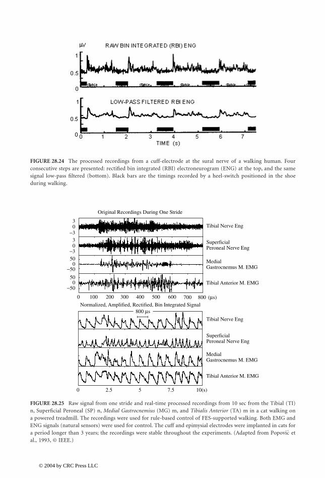
Neural Prostheses for Movement Restoration 28-27
FIGURE 28.24 The processed recordings from a cuff-electrode at the sural nerve of a walking human. Fourconsecutive steps are presented: rectified bin integrated (RBI) electroneurogram (ENG) at the top, and the samesignal low-pass filtered (bottom). Black bars are the timings recorded by a heel-switch positioned in the shoeduring walking.
FIGURE 28.25 Raw signal from one stride and real-time processed recordings from 10 sec from the Tibial (TI)n, Superficial Peroneal (SP) n, Medial Gastrocnemius (MG) m, and Tibialis Anterior (TA) m in a cat walking ona powered treadmill. The recordings were used for rule-based control of FES-supported walking. Both EMG andENG signals (natural sensors) were used for control. The cuff and epimysial electrodes were implanted in cats fora period longer than 3 years; the recordings were stable throughout the experiments. (Adapted from etal., 1993, © IEEE.)
−500
0
0 2.5 5 7.5 10(s)
100
Normalized, Amplified, Rectified, Bin Integrated Signal
200 300 400 500 600 700 800 (µs)
800 µs
50
0
0
50
3
03
−50
−3
−3
Original Recordings During One Stride
Tibial Anterior M. EMG
Tibial Anterior M. EMG
Gastrocnemus M. EMGMedial
Gastrocnemus M. EMGMedial
Peroneal Nerve EngSuperficial
Peroneal Nerve EngSuperficial
Tibial Nerve Eng
Tibial Nerve Eng
Popovic
1140_bookreps.fm Page 27 Tuesday, July 15, 2003 9:47 AM
© 2004 by CRC Press LLC
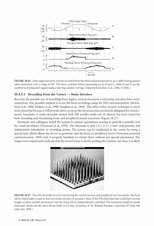
28-28 Biomedical Technology and Devices Handbook
28.4.3.3 Recording from the Cortex — Brain Interface
Recently, the possible use of recordings from higher cortical structures is attracting attention from manyresearchers. One possible method is to use the focal recordings using the EEG instrumentation (McFar-land et al., 1998; Wolpaw et al., 1998; Vaughan et al., 1998). The other rather invasive technique is muchmore attractive because it will provide direct access to the structures that are directly delegated for sensory-motor functions. A multi-electrode system with 100 needles made out of silicone has been tested forboth recording and stimulating brain and peripheral neural structures (Figure 28.27).
Normann and colleagues tested the system in animal experiments aiming to provide a possible toolfor visual prostheses (Normann et al., 1999). The electrode is only 2.5 ¥ 2.5 ¥ 2 mm3 and provides 100independent stimulation or recording points. The system can be implanted in the cortex by using aspecial tool, which allows the device to penetrate into the brain or peripheral nerve (Normann, personalcommunication, 1999) and, if properly installed, to remain there without any special attachment. Thelonger-term experiments indicate that the neural tissue is slowly pushing the implant out; thus, it is likely
FIGURE 28.26 Joint angle and nerve activity recorded from the tibial and peroneal nerves in a rabbit during passiveankle movement over a range of 60°. The nerve activities before processing are in B and C, while D and E are therectified and integrated signals using a moving window average. (Adapted from Riso et al., 2000, © IEEE.)
FIGURE 28.27 The 100-electrode array for interfacing the central nervous and peripheral nervous system. The backsilicon-based plate is used to host electronic circuitry if necessary. Each of the 100 electrodes that could have variouslengths to allow variable penetration into the tissue can be independently controlled. The maximum length of needleelectrodes (made out the same silicon bulk) is 2.5 mm. (Courtesy of Dr. Richard Norman, University of Utah, SaltLake City, 1998.)
0
5
0
−20
20
−20
20
130100 1 2 3 4 5
70
5
Peroneal Nerve Processed Eng (µV)
Peroneal Nerve Raw Eng (µV)
Tibial Nerve Processed Eng (µV)
Tibial Nerve Raw Eng (µV)
Joint Angle (deg)Flexion Extension
1 Second
A
B
C
D
E
1140_bookreps.fm Page 28 Tuesday, July 15, 2003 9:47 AM
© 2004 by CRC Press LLC
Neural Prostheses for Movement Restoration 28-29
that after some time, the electrode will not operate. The same electrode array is currently being testedin peripheral nerves and dorsal ganglion with great promises (Stein, personal communication, 2002).
28.4.4 Controller
A controller for NP is a system that has to be programmable to provide the following functions: (1) usedata from analog and analog sensors in real-time for sensory driven feed-forward or closed-loop control,(2) use switches for finite state control, and (3) generate signals that define the shape, amplitude, duration,and repetition rate of impulses to be delivered. Today many stimulation patterns are needed that requiresophisticated programming. A controller must produce sufficient number of output signals that accom-modate the stimulator number of channels. Today most microcontrollers can do the simple real-timecontrol, yet most are not capable of executing complex model-based control algorithms. Digital signalprocessors can be used, yet their power consumption is at this stage still questionable for portable, self-contained systems, especially implantable systems.
The controller should communicate with the host computer. This communication today can be easilyaccomplished by infrared communication, radio frequency transmission, or using USB and serial wire-based communication link. The host computer needs an interface that allows the user to efficientlyprogram the stimulation protocol with regard to number of channels to be used, number and type ofsensors and switches that will be applied, timing sequences, and special events. The host computerinterface must allow the user to potentially control the pulse amplitude and duration, repetition rate,and rise and fall time of the strength of stimulation.
The control schemes for different applications are explained in the text that follows.
28.5 Neural Prostheses for Restoring Upper and Lower Extremity Functions
During the last 40 years many NPs for restitution of upper and lower extremity functions have beendeveloped, yet only a few have reached the production of even prototype series for clinical studies. Themain reason is that the application of motor NP is extremely demanding and that in many cases thepathology does not allow sufficient improvement in function to make a NP effective enough. Many neuralprostheses are used for therapeutic purposes. The advancements of technology, better understanding ofsensory-motor systems, and greatly improved computer power that facilitates the implementation ofmuch more complex control schema raise great hopes for the future.
28.5.1 Neural Prostheses for Reaching and Grasping
NPs for upper limbs are being developed to establish and augment the independence to the user (Figure28.28). The target population for many years has been tetraplegics with diminished, yet preservedshoulder and elbow functions who lack wrist control and grasping ability (Triolo et al., 1996).
Controlling the movement of the whole arm has lately received more attention (Crago et al., 1998;Grill and Peckham, 1998; Lemay and Crago, 1997; and , 1998a, 1998b, 2000, 2001; Smithet al., 1996). The feasibility of restoring upper extremity function to individuals with high cervical spinalcord injury (C4 or higher) using FES and/or reconstructive surgery has been evaluated. Externallycontrolling movement to these individuals is challenging and not very successful for two primary reasons:(1) the number of retained voluntary functions is so low that there is a minimal opportunity to substitutefor lost functions or even to use these motions to control external devices; and (2) individuals with C3or C4 level spinal cord injuries exhibit extensive denervation of the shoulder and elbow muscles, whichlimits the possibility of using FES to restore movement.
The NP developed by and Vodovnik (1973) was one of the first FES systems for grasping.This NP had three stimulation channels (two stimulation electrodes per channel), used to generate thegrasping functions by stimulating the finger flexors and extensors, and the thumb flexors. Although this
Popovic Popovic
Rebersekˇ
1140_bookreps.fm Page 29 Tuesday, July 15, 2003 9:47 AM
© 2004 by CRC Press LLC
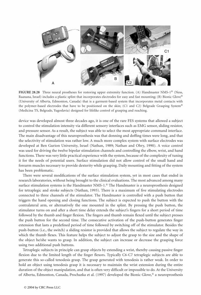
28-30 Biomedical Technology and Devices Handbook
device was developed almost three decades ago, it is one of the rare FES systems that allowed a subjectto control the stimulation intensity via different sensory interfaces such as EMG sensor, sliding resistor,and pressure sensor. As a result, the subject was able to select the most appropriate command interface.The main disadvantage of this neuroprosthesis was that donning and doffing times were long, and thatthe selectivity of stimulation was rather low. A much more complex system with surface electrodes wasdeveloped at Ben Gurion University, Israel (Nathan, 1989; Nathan and Ohry, 1990). A voice controlwas used for driving the twelve bipolar stimulation channels and controlling the elbow, wrist, and handfunctions. There was very little practical experience with the system, because of the complexity of tuningit for the needs of potential users. Surface stimulation did not allow control of the small hand andforearm muscles necessary to provide dexterity while grasping. Daily mounting and fitting of the systemhas been problematic.
There were several modifications of the surface stimulation system, yet in most cases that ended inresearch laboratories, without being brought to the clinical evaluations. The most advanced among manysurface stimulation systems is the Handmaster NMS-1.� The Handmaster is a neuroprosthesis designedfor tetraplegic and stroke subjects (Nathan, 1993). There is a maximum of five stimulating electrodesconnected to three channels of the stimulator. The Handmaster is controlled with a push button thattriggers the hand opening and closing functions. The subject is expected to push the button with thecontralateral arm, or alternatively the one mounted in the splint. By pressing the push button, thestimulator turns on and after a short time delay extends the subject’s fingers for a short period of timefollowed by the thumb and finger flexion. The fingers and thumb remain flexed until the subject pressesthe push button for the second time. The consecutive activation of the push-button generates fingerextension that lasts a predefined period of time followed by switching off of the stimulator. Besides thepush-button (i.e., the switch) a sliding resistor is provided that allows the subject to regulate the way inwhich the thumb flexes. This feature helps the subject to adjust the grasp to the size and the shape ofthe object he/she wants to grasp. In addition, the subject can increase or decrease the grasping forceusing two additional push buttons.
Tetraplegic subjects in principle can grasp objects by extending a wrist, thereby causing passive fingerflexion due to the limited length of the finger flexors. Typically C6-C7 tetraplegic subjects are able togenerate this so-called tenodesis grasp. The grasp generated with tenodesis is rather weak. In order tohold an object using tenodesis grasp it is necessary to maintain the wrist extension during the entireduration of the object manipulation, and that is often very difficult or impossible to do. At the Universityof Alberta, Edmonton, Canada, Prochazka et al. (1997) developed the Bionic Glove,� a neuroprosthesis
FIGURE 28.28 Three neural prostheses for restoring upper extremity function. (A) Handmaster NMS-1� (Ness,Raanana, Israel) includes a plastic splint that incorporates electrodes for easy and fast mounting; (B) Bionic Glove�
(University of Alberta, Edmonton, Canada) that is a garment-based system that incorporates metal contacts withthe polymer-based electrodes that have to be positioned on the skin; (C1 and C2) Belgrade Grasping System�
(Medicina TS, Belgrade, Yugoslavia) designed for lifelike control of grasping and reaching.
AB
C1
C2
1140_bookreps.fm Page 30 Tuesday, July 15, 2003 9:47 AM
© 2004 by CRC Press LLC

Neural Prostheses for Movement Restoration 28-31
that enhances the tenodesis grasp. The Bionic Glove applies a position transducer attached to the wristto detect voluntary wrist flexion and extension. When the patient flexes the wrist, the finger extensorsare stimulated causing hand opening. When the patient voluntarily extends the wrist, the finger flexorsare stimulated to provide hand closure. A dead-zone (hysteresis) allows movement of the wrist once the“open” or “close” stimulation pattern is activated. The electrical stimulation is provided via three self-adhesive surface stimulation electrodes that are placed over the muscles’ motor points, and an anodethat is placed proximal to the wrist crease. Each stimulation electrode has a metal stud on its back thatis connected to one of four stainless steel meshes placed inside the neoprene glove above the expectedelectrode positions. The stimulator and the position sensor used by the glove are located on the forearmpart of the glove. An easy-to-use interface with three push-buttons on the stimulator is used to set thestimulation parameters and the optional audio feedback that facilitates faster learning. To the best of theauthors’ knowledge, the Bionic Glove is not commercially available at the moment. The Bionic Glove iscurrently being modified and its new version named “Tetron” incorporates several grasping strategies.In the clinical evaluation ( et al., 1999) it was indicated that the stimulation is beneficial totetraplegic subjects (therapy effects and orthotic assistance), but that the overall acceptance rate for long-time use is at about 30% of potential users. One of the conclusions was that the control, donning, anddoffing should be improved, as well as its cosmetic appearance.
The Belgrade Grasping/Reaching System (BGS�) is a four-channel system ( and ,1998a; 1998b) allowing two modalities of grasping: side and palm grasps by generating opposition andcontrol of elbow movement. A preprogrammed sequence is triggered using a switch interface, similar tothe Handmaster system. The grasping is separated into three phases: (1) prehension (forming the correctaperture); (2) relaxing (allowing the hand to get good contact with the object); and (3) closing the handby opposing the palm and the thumb or the side of the index finger and the thumb. The releasing functionincludes two stages: opening of the hand and resting. It is possible to select the duration of each of thephases of the grasp/release upon the individual characteristics of the subject, as well as his/her preferences.The BGS comprises also a reaching controller. The system uses synergistic control based on mapping ofthe angular velocities at the shoulder and elbow joints ( and , 2001).
The ETHZ-ParaCare� neuroprosthesis was designed recently with the aim to improve grasping andwalking functions in SCI and stroke patients ( et al., 2001). This four-channel NP is program-mable and can be interfaced with many sensors used as feedback or trigger generators. The ETHZ-ParaCare NP provides both palmar and lateral grasps. The controller includes four modalities: propor-tional EMG, discrete EMG, push button, and sliding resistor strategies. Thus far more than 12 patientshave used the system. Four patients used the neuroprosthesis at home in daily living activities. One ofthe main disadvantages of this system is that it requires between 7 and 10 min to don and doff the system.The system is not yet commercially available. Current efforts are aimed at completing a new generationof the neuroprosthesis that could be used for all FES applications involving surface stimulation electrodes.The ParaCare grasping devices were transferred to Compex Motion Company, Switzerland; the newneuroprosthesis, called Compex Motion� (beta version), became available at the end of 2001.
The likely method to overcome problems of surface electrodes NP for reaching and grasping andreaching, is to use implanted electrode or eventually fully implantable systems. This problem wasaddressed for more than 20 years in a systematic way in Japan (Handa et al., 1989a; 1998b). Subjectshave been implanted with up to 30 percutaneous i.m. electrodes per extremity. These electrodes wereconnected to a 30-channel device that delivers a preprogrammed sequence of stimulation pulses. Thepreprogrammed sequence was prepared based on the activity of muscles recorded in able-bodied subjects.The i.m. EMG determined the pattern of muscle activity in able-bodied subjects. This stimulationprogram in the Sendai Hospital, Japan was most often applied as a therapy, with a plan to design a self-contained orthosis for daily continuous usage.
The most advanced grasping NP follows from more than 20 years of dedicated work by Peckham(Peckham et al., 1980a, 1980b) from the Case Western Reserve University (CWRU), Cleveland, Ohio. Afully implantable stimulation device (Figure 28.29) is approved for human use under the name Freehandsystem,� distributed by the NeuroControl Corp. of Cleveland, Ohio. The system has an external unit
Popovic
Popovic Popovic
Popovic Popovic
Popovic
1140_bookreps.fm Page 31 Tuesday, July 15, 2003 9:47 AM
© 2004 by CRC Press LLC
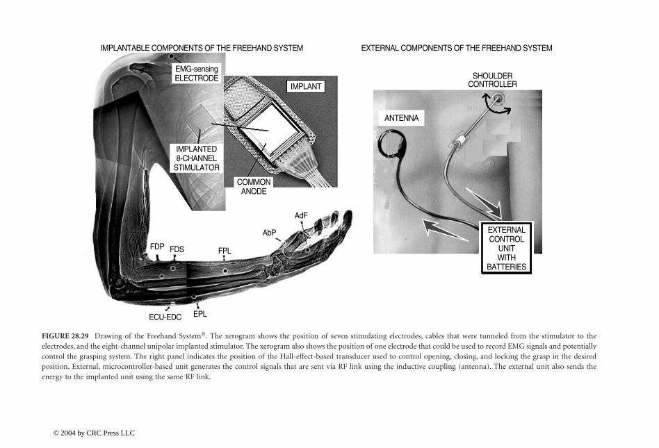
28-32B
iomed
ical Techn
ology and
Devices H
and
book
FIGURE 28.29 Drawing of the Freehand System�. The xerogram shows the position of seven stimulating electrodes, cables that were tunneled from the stimulator to theelectrodes, and the eight-channel unipolar implanted stimulator. The xerogram also shows the position of one electrode that could be used to record EMG signals and potentiallycontrol the grasping system. The right panel indicates the position of the Hall-effect-based transducer used to control opening, closing, and locking the grasp in the desiredposition. External, microcontroller-based unit generates the control signals that are sent via RF link using the inductive coupling (antenna). The external unit also sends theenergy to the implanted unit using the same RF link.
IMPLANTABLE COMPONENTS OF THE FREEHAND SYSTEM EXTERNAL COMPONENTS OF THE FREEHAND SYSTEM
SHOULDERCONTROLLER
ANTENNA
IMPLANT
IMPLANTED8-CHANNEL
STIMULATOR
COMMONANODE
EMG-sensingELECTRODE
AdF
AbP
FPLFDSFDP
EPLECU-EDC
EXTERNALCONTROL
UNITWITH
BATTERIES
1140_bookreps.fm Page 32 T
uesday, July 15, 2003 9:47 AM
© 2004 by CRC Press LLC
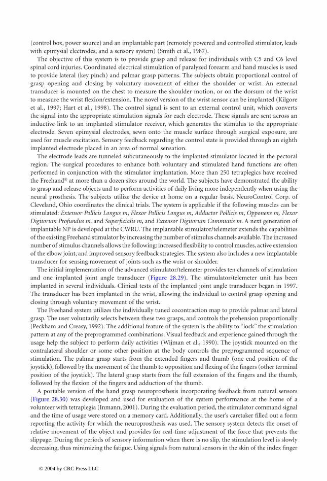
Neural Prostheses for Movement Restoration 28-33
(control box, power source) and an implantable part (remotely powered and controlled stimulator, leadswith epimysial electrodes, and a sensory system) (Smith et al., 1987).
The objective of this system is to provide grasp and release for individuals with C5 and C6 levelspinal cord injuries. Coordinated electrical stimulation of paralyzed forearm and hand muscles is usedto provide lateral (key pinch) and palmar grasp patterns. The subjects obtain proportional control ofgrasp opening and closing by voluntary movement of either the shoulder or wrist. An externaltransducer is mounted on the chest to measure the shoulder motion, or on the dorsum of the wristto measure the wrist flexion/extension. The novel version of the wrist sensor can be implanted (Kilgoreet al., 1997; Hart et al., 1998). The control signal is sent to an external control unit, which convertsthe signal into the appropriate stimulation signals for each electrode. These signals are sent across aninductive link to an implanted stimulator receiver, which generates the stimulus to the appropriateelectrode. Seven epimysial electrodes, sewn onto the muscle surface through surgical exposure, areused for muscle excitation. Sensory feedback regarding the control state is provided through an eighthimplanted electrode placed in an area of normal sensation.
The electrode leads are tunneled subcutaneously to the implanted stimulator located in the pectoralregion. The surgical procedures to enhance both voluntary and stimulated hand functions are oftenperformed in conjunction with the stimulator implantation. More than 250 tetraplegics have receivedthe Freehand� at more than a dozen sites around the world. The subjects have demonstrated the abilityto grasp and release objects and to perform activities of daily living more independently when using theneural prosthesis. The subjects utilize the device at home on a regular basis. NeuroControl Corp. ofCleveland, Ohio coordinates the clinical trials. The system is applicable if the following muscles can bestimulated: Extensor Pollicis Longus m, Flexor Pollicis Longus m, Adductor Pollicis m, Opponens m, FlexorDigitorum Profundus m. and Superficialis m, and Extensor Digitorum Communis m. A next generation ofimplantable NP is developed at the CWRU. The implantable stimulator/telemeter extends the capabilitiesof the existing Freehand stimulator by increasing the number of stimulus channels available. The increasednumber of stimulus channels allows the following: increased flexibility to control muscles, active extensionof the elbow joint, and improved sensory feedback strategies. The system also includes a new implantabletransducer for sensing movement of joints such as the wrist or shoulder.
The initial implementation of the advanced stimulator/telemeter provides ten channels of stimulationand one implanted joint angle transducer (Figure 28.29). The stimulator/telemeter unit has beenimplanted in several individuals. Clinical tests of the implanted joint angle transducer began in 1997.The transducer has been implanted in the wrist, allowing the individual to control grasp opening andclosing through voluntary movement of the wrist.
The Freehand system utilizes the individually tuned cocontraction map to provide palmar and lateralgrasp. The user voluntarily selects between these two grasps, and controls the prehension proportionally(Peckham and Creasy, 1992). The additional feature of the system is the ability to “lock” the stimulationpattern at any of the preprogrammed combinations. Visual feedback and experience gained through theusage help the subject to perform daily activities (Wijman et al., 1990). The joystick mounted on thecontralateral shoulder or some other position at the body controls the preprogrammed sequence ofstimulation. The palmar grasp starts from the extended fingers and thumb (one end position of thejoystick), followed by the movement of the thumb to opposition and flexing of the fingers (other terminalposition of the joystick). The lateral grasp starts from the full extension of the fingers and the thumb,followed by the flexion of the fingers and adduction of the thumb.
A portable version of the hand grasp neuroprosthesis incorporating feedback from natural sensors(Figure 28.30) was developed and used for evaluation of the system performance at the home of avolunteer with tetraplegia (Inmann, 2001). During the evaluation period, the stimulator command signaland the time of usage were stored on a memory card. Additionally, the user’s caretaker filled out a formreporting the activity for which the neuroprosthesis was used. The sensory system detects the onset ofrelative movement of the object and provides for real-time adjustment of the force that prevents theslippage. During the periods of sensory information when there is no slip, the stimulation level is slowlydecreasing, thus minimizing the fatigue. Using signals from natural sensors in the skin of the index finger
1140_bookreps.fm Page 33 Tuesday, July 15, 2003 9:47 AM
© 2004 by CRC Press LLC
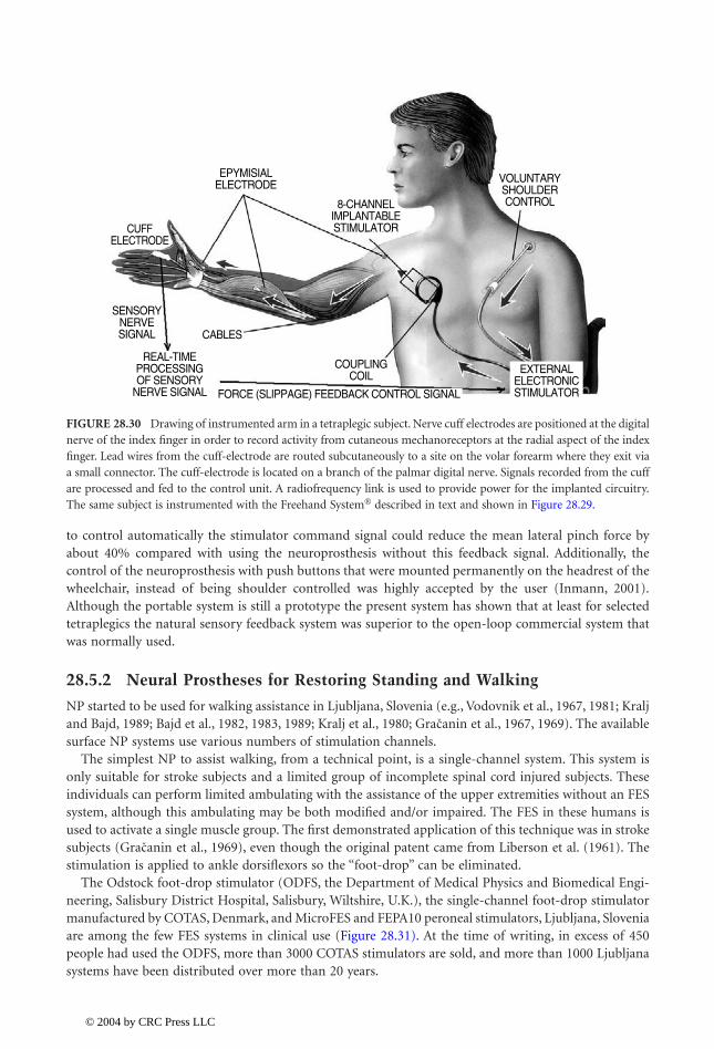
28-34 Biomedical Technology and Devices Handbook
to control automatically the stimulator command signal could reduce the mean lateral pinch force byabout 40% compared with using the neuroprosthesis without this feedback signal. Additionally, thecontrol of the neuroprosthesis with push buttons that were mounted permanently on the headrest of thewheelchair, instead of being shoulder controlled was highly accepted by the user (Inmann, 2001).Although the portable system is still a prototype the present system has shown that at least for selectedtetraplegics the natural sensory feedback system was superior to the open-loop commercial system thatwas normally used.
28.5.2 Neural Prostheses for Restoring Standing and Walking
NP started to be used for walking assistance in Ljubljana, Slovenia (e.g., Vodovnik et al., 1967, 1981; Kraljand Bajd, 1989; Bajd et al., 1982, 1983, 1989; Kralj et al., 1980; et al., 1967, 1969). The availablesurface NP systems use various numbers of stimulation channels.
The simplest NP to assist walking, from a technical point, is a single-channel system. This system isonly suitable for stroke subjects and a limited group of incomplete spinal cord injured subjects. Theseindividuals can perform limited ambulating with the assistance of the upper extremities without an FESsystem, although this ambulating may be both modified and/or impaired. The FES in these humans isused to activate a single muscle group. The first demonstrated application of this technique was in strokesubjects ( et al., 1969), even though the original patent came from Liberson et al. (1961). Thestimulation is applied to ankle dorsiflexors so the “foot-drop” can be eliminated.
The Odstock foot-drop stimulator (ODFS, the Department of Medical Physics and Biomedical Engi-neering, Salisbury District Hospital, Salisbury, Wiltshire, U.K.), the single-channel foot-drop stimulatormanufactured by COTAS, Denmark, and MicroFES and FEPA10 peroneal stimulators, Ljubljana, Sloveniaare among the few FES systems in clinical use (Figure 28.31). At the time of writing, in excess of 450people had used the ODFS, more than 3000 COTAS stimulators are sold, and more than 1000 Ljubljanasystems have been distributed over more than 20 years.
FIGURE 28.30 Drawing of instrumented arm in a tetraplegic subject. Nerve cuff electrodes are positioned at the digitalnerve of the index finger in order to record activity from cutaneous mechanoreceptors at the radial aspect of the indexfinger. Lead wires from the cuff-electrode are routed subcutaneously to a site on the volar forearm where they exit viaa small connector. The cuff-electrode is located on a branch of the palmar digital nerve. Signals recorded from the cuffare processed and fed to the control unit. A radiofrequency link is used to provide power for the implanted circuitry.The same subject is instrumented with the Freehand System� described in text and shown in Figure 28.29.
CUFFELECTRODE
SENSORYNERVESIGNAL
REAL-TIMEPROCESSINGOF SENSORY
NERVE SIGNAL FORCE (SLIPPAGE) FEEDBACK CONTROL SIGNAL
COUPLINGCOIL
CABLES
EXTERNALELECTRONICSTIMULATOR
8-CHANNELIMPLANTABLESTIMULATOR
EPYMISIALELECTRODE VOLUNTARY
SHOULDERCONTROL
Gracaninˇ
Gracaninˇ
1140_bookreps.fm Page 34 Tuesday, July 15, 2003 9:47 AM
© 2004 by CRC Press LLC
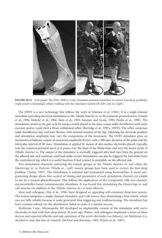
Neural Prostheses for Movement Restoration 28-35
The ODFS is a new technology that follows the work of Liberson et al. (1961). It is a single-channelstimulator providing electrical stimulation to the Tibialis Anterior m. or the common peroneal nerve (Granatet al., 1996; et al., 1984; Stein et al., 1993; Sweeney and Lyons, 1999; Wieler et al., 1999). Thestimulation, timed to the gait cycle by using a switch placed in the shoe, causes ankle dorsiflexion with someeversion and/or could elicit a flexor withdrawal reflex (Burridge et al., 1997a, 1997b). The reflex comprisesankle dorsiflexion, hip, and knee flexion, with external rotation of the hip. Adjusting the electrode positionand stimulation amplitude may vary the components of the movement. The ODFS stimulator gives anasymmetrical biphasic output of maximum amplitude 80 mA, with a 300-µsec duration of the pulse and theinterpulse interval of 40 msec. Stimulation is applied by means of skin-surface electrodes placed, typically,over the common peroneal nerve as it passes over the head of the fibula bone and over the motor point ofTibialis Anterior m. The output of the stimulator is normally triggered after heel rises from the ground onthe affected side and continues until heel strike occurs. Stimulation can also be triggered by heel strike fromthe contralateral leg, which is a useful function if heel contact is unreliable on the affected side.
Two stimulation channels; restricting the muscle groups to the Tibialis Anterior m. and either theHamstrings m. or Posterior Tibialis m., (calf) muscle groups have been used to correct the foot-dropproblem (Taylor, 1997). The stimulation is initiated and terminated using footswitches. A novel pro-gramming design allows fine control of timing and parameters of each stimulation channel, yet simpleto use by a trained physiotherapist. This follows the application of the Compustim-10B, two-channel,microcontroller-based, neuromuscular stimulator. It was found that stimulating the Hamstrings m. andcalf muscles (in addition to the Tibialis Anterior m.) is most effective.
Stein and colleagues (Dai et al., 1996) have designed an appealing self-contained drop-foot system.The system integrates a single-channel stimulator and a tilt sensor, thus eliminating a foot switch, whichwas not fully reliable because it easily generated false triggering and malfunctioning. The stimulator hasbeen commercialized, yet the distribution failed to make it a market success.
Medtronic Corp., Minneapolis, MI developed an implantable version of the stimulator with nerveelectrodes to deal with foot-drop almost 30 years ago. Waters and colleagues implanted a series of thesedevices and reported effective and safe operation of the nerve electrodes (no failures), yet Medtronic Co.decided to stop this line of research (McNeal and Bowman, 1985; Waters et al., 1985).
FIGURE 28.31 (Left panel) The KDC 2000A, Cotas, Denmark peroneal stimulator to correct foot-drop problems;(right panel) a hemiplegic subject walking with the stimulator turned off (left) and on (right).
Malezicˇ ˇ
1140_bookreps.fm Page 35 Tuesday, July 15, 2003 9:47 AM
© 2004 by CRC Press LLC

28-36 Biomedical Technology and Devices Handbook
The fully implantable stimulator IPPO (Figure 28.18) has been tested in more than 20 subjects afterthey had already used the surface stimulation system (Strojnik et al., 1987). The walking pattern did notchange with the implanted stimulator compared with the surface electrode based device; however, theease of application, reproducibility, and cosmetic appearance improved greatly. The implantation isrelatively simple, and it is performed in daily surgery.
The dual channel stimulator can be used to correct eversion/inversion of the foot in addition to thedorsiflexion (Hansen, 2001). This new system comprises a cuff-electrode for recording of sensory infor-mation from cutaneous receptors. The rationale for implanting a cuff electrode on a cutaneous nerveinnervating the foot is to remove the external heel switch used in existing systems for foot-drop correction.Thereby, it is possible to use such systems without footwear and to prepare them to be totally implantablesystems. After processing the nerve signal heel contacts can be detected using the afferent nerve signalinformation alone (Hansen et al., 1998; Kostov et al., 1999) for deciding when the muscle that preventsfoot-drop must be stimulated during gait (Figure 28.32).
A multichannel system with a minimum of four channels of FES is required for ambulating of a subjectwith a complete motor lesion of lower extremities and preserved balance and upper body motor control(Kralj and Bajd, 1989). Appropriate bilateral stimulation of the quadriceps muscles locks the knees duringstanding (Bajd et al., 1982; Jaeger et al., 1989). Stimulating the common peroneal nerve on the ipsilateralside, while switching off the quadriceps stimulation on that side, produces a flexion of the leg. Thisflexion, combined with adequate movement of the upper body and use of the upper extremities forsupport, allows ground clearance and is considered the swing phase of the gait cycle. Hand or footswitches can provide the flexion-extension alternation needed for a slow forward or backward progression(Figure 28.33). Sufficient arm strength must be available to provide balance in parallel bars (clinicalapplication), and with a rolling walker or crutches (daily use of FES).
FIGURE 28.32 The new development of the fully implantable system for correcting foot-drop. The neural signalis used (cuff-electrode) for recording of the necessary information for steering of the stimulation; the second cuffis used for selective stimulation of the nerve to allow the appropriate dorsiflexion, controlled inversion/eversion,and internal/external rotation of the foot. The external battery-powered, self-contained unit is providing energy,processing the neural signal based on off-line determined mappings (adaptive logic networks), and deliveringcontrol signals for stimulation.
IMPLANTEDRECEIVER
IMPLANTEDAMPLIFIER
RECORDINGCUFF
ELECTRODE
RF LINK
RF LINK
TRANSMITTERANTENNA
EXTERNALUNIT
TRANSMITTERANTENNA
MULTI-CHANNELSTIMULATOR
1140_bookreps.fm Page 36 Tuesday, July 15, 2003 9:47 AM
© 2004 by CRC Press LLC
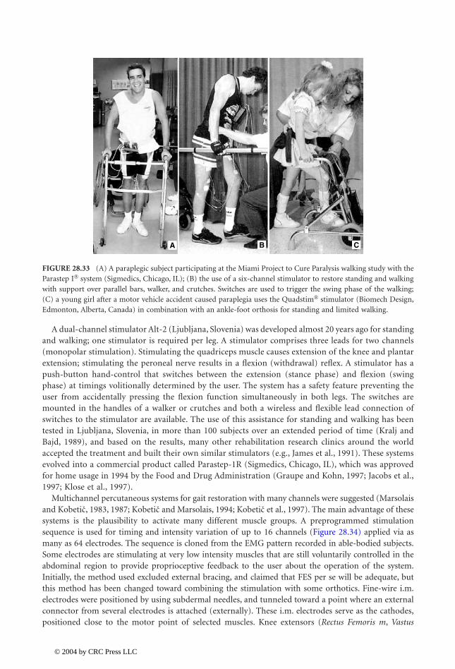
Neural Prostheses for Movement Restoration 28-37
A dual-channel stimulator Alt-2 (Ljubljana, Slovenia) was developed almost 20 years ago for standingand walking; one stimulator is required per leg. A stimulator comprises three leads for two channels(monopolar stimulation). Stimulating the quadriceps muscle causes extension of the knee and plantarextension; stimulating the peroneal nerve results in a flexion (withdrawal) reflex. A stimulator has apush-button hand-control that switches between the extension (stance phase) and flexion (swingphase) at timings volitionally determined by the user. The system has a safety feature preventing theuser from accidentally pressing the flexion function simultaneously in both legs. The switches aremounted in the handles of a walker or crutches and both a wireless and flexible lead connection ofswitches to the stimulator are available. The use of this assistance for standing and walking has beentested in Ljubljana, Slovenia, in more than 100 subjects over an extended period of time (Kralj andBajd, 1989), and based on the results, many other rehabilitation research clinics around the worldaccepted the treatment and built their own similar stimulators (e.g., James et al., 1991). These systemsevolved into a commercial product called Parastep-1R (Sigmedics, Chicago, IL), which was approvedfor home usage in 1994 by the Food and Drug Administration (Graupe and Kohn, 1997; Jacobs et al.,1997; Klose et al., 1997).
Multichannel percutaneous systems for gait restoration with many channels were suggested (Marsolaisand , 1983, 1987; and Marsolais, 1994; et al., 1997). The main advantage of thesesystems is the plausibility to activate many different muscle groups. A preprogrammed stimulationsequence is used for timing and intensity variation of up to 16 channels (Figure 28.34) applied via asmany as 64 electrodes. The sequence is cloned from the EMG pattern recorded in able-bodied subjects.Some electrodes are stimulating at very low intensity muscles that are still voluntarily controlled in theabdominal region to provide proprioceptive feedback to the user about the operation of the system.Initially, the method used excluded external bracing, and claimed that FES per se will be adequate, butthis method has been changed toward combining the stimulation with some orthotics. Fine-wire i.m.electrodes were positioned by using subdermal needles, and tunneled toward a point where an externalconnector from several electrodes is attached (externally). These i.m. electrodes serve as the cathodes,positioned close to the motor point of selected muscles. Knee extensors (Rectus Femoris m, Vastus
FIGURE 28.33 (A) A paraplegic subject participating at the Miami Project to Cure Paralysis walking study with theParastep I� system (Sigmedics, Chicago, IL); (B) the use of a six-channel stimulator to restore standing and walkingwith support over parallel bars, walker, and crutches. Switches are used to trigger the swing phase of the walking;(C) a young girl after a motor vehicle accident caused paraplegia uses the Quadstim� stimulator (Biomech Design,Edmonton, Alberta, Canada) in combination with an ankle-foot orthosis for standing and limited walking.
A B C
Kobetic Kobetic Kobetic
1140_bookreps.fm Page 37 Tuesday, July 15, 2003 9:47 AM
© 2004 by CRC Press LLC

28-38 Biomedical Technology and Devices Handbook
Medialis m, Vastus Lateralis m, Vastus Intermedius m), hip flexors (Sartorius m, Tensor Fasciae Latae m,Gracilis m, Iliopsoas m.), hip extensors (Semimembranosus m, Gluteus Maximus m.), hip abductors(Gluteus Medius m), ankle dorsiflexors (Tibialis Anterior m, Peroneus Longus m), ankle plantar flexors(Gastrocnemius Lateralis m, Gastrocnemius Medialis m, Plantaris m, Soleus m), and paraspinal musclesare selected for activation. A surface electrode has been used as a common anode. Interleaved pulsesare delivered with a multichannel, battery-operated, portable stimulator. The hand controller allowsthe selection of the walking modality. The CWRU system allowed selected humans to walk up to 1.1m/sec, and walk distances of almost 1000 m. The preprogrammed stimulation sequence included thefollowing walking modes: standing up, sitting down, standing, walking, walking stairs or curb, walkingbackwards.
Recent projects somewhat changed the initial emphasis of research with implanted systems at theCWRU/Veteran Administration (VA) Center, Cleveland, OH ( et al., 1999; Sharma et al., 1998).Providing a device to exercise, stand, and maneuver in the vicinity of the wheelchair to individualswith spinal cord injuries (SCIs) through the application of FES is now the primary goal; a systemnamed Freestand, which follows the design of the Freehand, is approved for clinical studies. A single8-channel CWRU/VA implanted receiver-stimulator (IRS-8) could be used for exercise and standingin individuals with complete motor deficits, and to facilitate walking in selected individuals with partialparalysis. The plan is also to combine both 8- to 16-channel muscle stimulators with a trunk-hip-knee-ankle-foot orthosis with programmable joint locks. The purpose is to provide more immediatemobility to paraplegic individuals and to study functional mobility requirements using the implantabledevices currently available.
A different approach to using a multichannel totally implanted FES system (Thoma et al., 1978,1987) was proposed and tested in a few subjects. This system used a 16-channel implantable stimulator.The electrodes were attached to the epineurium of the selected nerves. Femoral and gluteal nerveswere stimulated for hip and knee extension. The so-called “round-about” stimulation was applied inwhich four electrodes were located around the nerve and stimulated intermittently. This stimulationmethod was selected to provide physiological-like firing rate to reduce muscle fatigue. The method isfinding its extension with the new electrode design that allows selective stimulation of specific fascicleswithin a nerve.
In 1991 the first 22-channel FES system based on the Nucleus FES22, Cochlear Ltd., Australia, wasimplanted in a T10-paraplegic male. After a considerable time of training and fitting the program it waspossible to achieve sensory feedback-driven standing for about 1 h (Davis et al., 1997). The sensory
FIGURE 28.34 Paraplegic subject walking with a 16-channel stimulator applied via percutaneous i.m. electrodes.The further development of systems for walking and standing continues with epimysial and i.m. electrodes, yet witha fully implantable system based on the technology developed for the Freehand System�.
Kobetic
1140_bookreps.fm Page 38 Tuesday, July 15, 2003 9:47 AM
© 2004 by CRC Press LLC
Neural Prostheses for Movement Restoration 28-39
signals were acquired from the electro-goniometers at the knee joints. Stance stability was assistedwith the Andrews’ Anterior Floor Reaction Orthosis. The closed-loop control minimizes the time ofstimulation; only about 10% of the total standing time are the muscles are externally activated. In1998, a second T10-paraplegic male was implanted with an updated 22-channel stimulator withtelemetry (FES24-A, Neopraxis Pty Ltd, Lane Cove, N.S.W., Australia). Eighteen channels are connectedto epineural electrodes on nerves for muscle activation and limb movements thereby allowing exerciseand open-loop standing for 30 min. The Praxis FES24-A is a multifunctional stimulator. Ten electrodesare thin, flexible platinum cuffs (Flexi-Cuff), at least twice the diameter of encircled nerve. Eight otherelectrodes are button-shaped, made of platinum, and placed on the epineurium. Each button has anattached Dacron mesh that is used to suture the electrode to the adjacent connective tissue. Thestimulation originates from an external, battery-operated, belt-worn controller (Navigator) microcon-troller. The stimulation is delivered via an external RF linked antenna that is magnetically held to theskin by an underlying magnet in the implant. The stimulation parameters are 6.0 to 8.0 mA, with 25-to 500-msec pulse width and a frequency of up to 60 pulses per second per electrode. The user canselect different strategies via a menu-driven protocol based on a simple LCD and keypad interface. Aremote RF-linked button is being developed for finger control to complement the keypad. The sensorysystem comprises two accelerometers and a rate gyroscope.
28.5.2.1 Hybrid Assistive Systems
In order to minimize problems due to the muscle fatigue and to increase the safety, a combination of amechanical orthosis and FES was suggested. The resulting orthosis is called Hybrid assistive system orHybrid orthosis ( et al., 1989; et al., 1995). The support, stability of the joints, andconstraint to unwanted motion of the joints are provided by the mechanical component of the orthosis,while FES provides propulsion. Schwirtlich and (1984) suggested a hybrid orthosis that consistedof the self-fitting modular orthosis (SFMO) and surface electrodes FES to provide the knee extensionand swing of the leg during walking. A four-channel stimulator was used. The user initiates steps bytriggering flexion, and this is followed by sensory-driven knee extensor activity. The SFMO used brakesactivated by a micromotor (Schwirtlich and , 1984).
Andrews and Bajd (1984) suggested two variants of hybrid orthoses. One consisted of a combinationof a pair of simple plastic splints used to maintain the knee extension and a two-channel stimulator perleg. One channel stimulated gastro-soleus muscles, and the other provided flexor withdrawal response.Since the knee was held in extension, only dorsiflexion of the foot and flexion of the hip were obtained.The other hybrid system comprised the KAFO and two-channel stimulation per leg, The quadriceps andcommon peroneal nerve were stimulated on each side. The quadriceps stimulation caused knee extension,and the peroneal nerve stimulation produced synergistic flexor response. The mechanical brace incor-porated knee joint locks, which were remotely controlled by a solenoid actuator or a Bowden cable.
Andrews and associates (1988) suggested a different way of using the floor reaction orthosis (FOR) inconjunction with FES. This consisted of a rigid ankle foot orthosis, a multichannel stimulator with surfaceelectrodes, body-mounted sensors, a “rule-based” controller, and an electrocutaneous display for sup-plementary feedback. The finite state controller reacted automatically to destabilize shifts of the groundreaction vector by stimulating appropriate antigravity musculature to brace the leg, The system alsofeatured a control mode to initiate and terminate flexion of the leg during forward progression. A simplemode of supplementary sensory feedback was used during the laboratory standing tests to assist thesubject in maintaining the posture.
Solomonow and associates (1989) suggested a hybrid-assistive system that combines FES and recip-rocating gait orthosis. The reciprocating gait orthosis was jointly developed by the Louisiana StateUniversity Medical Center and Durr-Fillauer Medical Inc. (Douglas et al., 1983). The orthosis includestrunk support, a pelvic assembly, and bilateral knee-ankle-foot-orthosis (KAFO). A rigid pelvic assemblyconsisting of a pelvic band covering the gluteal and sacral areas bears hip joints. KAFO have posterioroffset of the knee joints with drop locks on the lateral sides. The most important feature of the systemis the cable coupling of the left and right leg movement. The coupling provides hip joint stability during
Popovic Tomovic
Popovic
Popovic
1140_bookreps.fm Page 39 Tuesday, July 15, 2003 9:47 AM
© 2004 by CRC Press LLC

28-40 Biomedical Technology and Devices Handbook
standing by preventing simultaneous flexion of both hips, yet it allows flexion of one hip and simultaneousextension of the other when a step is taken. The cables can be disengaged to sit down. The FES part ofthe hybrid system is used for standing up as well as for the swing of the legs. Surface stimulation of RectusFemoris m. and Hamstrings m was applied, and the stimulation electrodes were incorporated in a plasticpolymer cuff. The electrode cuffs were secured on the thighs with Velcro straps. A four-channel stimulatorwas worn on a belt. Finger switches were mounted on the handles of the walker. The subject controlledthe stimulation himself. Phillips (1989) described a similar system; in addition to the stimulation ofHamstrings m, the stimulation of ipsilateral Gluteus m was also suggested to improve hip extension ofthe stance leg, Four two-channel stimulators were used to achieve these functions. The entire bulk ofQuadriceps m. was stimulated using three-electrode configuration with two channels of one stimulatorfor each leg, The other two stimulators were used to stimulate Hamstrings m and Gluteus m on each side.
References
Andrews, B.J. and Bajd, T., Hybrid orthosis for paraplegics, in Advances in External Control of HumanExtremities, , D.B., Ed., Yugoslav Committee for ETAN (Suppl.), Belgrade, 1984, pp. 55–57.
Andrews, B.J., Baxendale, R.H., Barnett, R., Philips, G.F., Yamazaki, T., Paul, J.P., and Freeman, P.A.,Hybrid FES orthosis incorporating closed loop control and sensory feedback, J. Biomed. Eng.,10(2), 189–195, 1988.
Bajd, T. and Bowman, B., Testing and modelling of spasticity, Biomed. Eng., 4, 90–96, 1982.Bajd, T., , M., Vodovnik, L., and Benko, H., Electrical stimulation in treating spasticity resulting
from spinal cord injury, Arch. Phys. Med. Rehabil., 66, 515–517, 1985.Bajd, T., Kralj, A., and Turk, R., Standing-up of a healthy subject and a paraplegic patients, J. Biomech.,
15, 1–10, 1982.Bajd, T., Kralj, A., Turk, R., Benko, H., and , J., The use of a four channel electrical stimulator as an
ambulatory aid for paraplegic patients, Phys. Ther., 63, 1116–1120, 1983.Bajd, T., Kralj, A., Turk, R., Benko, H., and , J., Use of functional electrical stimulation in the
rehabilitation of patients with incomplete spinal cord injuries, J. Biomed. Eng., 11, 96–102, 1989.Bajzek, T.J. and Jaeger, R.J., Characterization and control of muscle response to electrical stimulation,
Ann. Biomed. Eng., 15, 485–501, 1987.Baratta, R. and Solomonow, M., The dynamic response model of nine different skeletal muscles, IEEE
Trans. Biomed. Eng., BME-37, 243–251, 1990.Baratta, R., Zhou, B.H., and Solomonow, M., Frequency response model of skeletal muscle: effect of
perturbation level, and control strategy, Med. Biol. Eng. Comput., 27(4), 337–345, 1989.Barbeau, H., McCrea, D.A., O’Donovan, D.J., Rossignol, S., Grill, W.M., and Lemay, M.A., Tapping into
spinal circuits to restore motor function, Brain Res. Rev., 30, 27–51, 1999.Bijak, M., Sauerman, S., Schmutterer, C., Lanmueller, H., Unger, E., and Mayr, W., A modular PC-based
system for easy setup of complex stimulation patterns, Proc 4th Intern. Conf. IFESS, Sendai, 1999,pp. 28–32.
Bogataj, U., Gros, N., , M., Kelih, B., , M., and , R., Restoration of gait duringtwo to three weeks of therapy with multichannel electrical stimulation, Phys. Ther., 69(5), 319–327,1989.
Bowman, B. and Baker, L., Effects of waveform parameters on comfort during transcutaneous neuro-muscular electrical stimulation. Ann. Biomed. Eng., 13, 59–74, 1985.
Bowman, R.B. and Erickson, R.C., Acute and chronic implantation of coiled wire intraneural electrodesduring cyclical electrical stimulation, Ann. Biomed. Eng., 13, 75–93, 1985.
Brindley, G.S., Polkey, C.E., and Rushton, D.N., Electrical splinting of the knee in paraplegia, Paraplegia,16, 428–435, 1978.
Brodmann, K., Vergleichende Lokalisationslehre der Grosshirnrinde in ibren Prinziplen dargestelit aufGrund des Zellenbaues. Barth, Leipzig, 1909.
Popovic
Gregoric
Segaˇ
Segaˇ
Malezicˇ ˇ Kljajic Acimovic´ ´
1140_bookreps.fm Page 40 Tuesday, July 15, 2003 9:47 AM
© 2004 by CRC Press LLC
Neural Prostheses for Movement Restoration 28-41
Buckett, J.R., Peckham, P.H., Thrope, G.B., Braswell, S.D., and Keith, M.W., A flexible, portable systemfor neuromuscular stimulation in the paralyzed upper extremity, IEEE Trans. Biomed. Eng., BME-35, 897–904, 1988.
Burridge, J.H., Taylor, P.N., Hagan, S., and Swain, I.D., Experience of clinical use of the Odstock droppedfoot stimulator, Artif. Organs, 21(3), 254–260, 1997a.
Burridge, J.H., Taylor, P.N., Hagan, S., Wood, D.E., and Swain, I.D., The effects of common peronealstimulation on the effort and speed of walking: a randomized controlled trial with chronic hemi-plegic patients, Clin. Rehabil., 11(3), 201–210, 1997b.
Cameron, T., Loeb, G.E., Peck, R.A., Schulman, J.H., Strojnik, P., and Troyk, P.R., Micromodular implantsto provide electrical stimulation of paralyzed muscles and limbs, IEEE Trans. Biomed. Eng., BME-44(9), 781–790, 1997.
Coulombe, R.F., Fiber optic sensors — catching up with the 1980s, Sensors, 1(12), 5–11, 1984.Crago, P.E., Peckham, P.H., Mortimer, J.T., and Van der Meulen, J., The choice of pulse duration for
chronic electrical stimulation via surface, nerve and intramuscular electrodes, Ann. Biomed. Eng.,2, 252–264, 1974.
Crago, P.E., Peckham, P.H., and Thrope, G.B., Modulation of muscle force by recruitment during intra-muscular stimulation, IEEE Trans. Biomed. Eng., BME-27(12), 679–684, 1980.
Crago, P.E., Chizeck, H.J., Neuman, M.R., and Hambrecht, F.T., Sensors for use with functional neuro-muscular stimulation, IEEE Trans. Biomed. Eng., BME-33(2), 256–268, 1986.
Crago, P.E., Memberg, W.D., Usey, M.K., Keith, M.W., Kirsch, R.F., Chapman, G.J., et al., An elbowextension neuroprosthesis for individuals with tetraplegia, IEEE Trans. Rehabil. Eng., TRE-6(1),1–6, 1998.
Dai, R., Stein, R.B., Andrews, B.J., James, K.B., and Wieler, M., Application of tilt sensors in functionalelectrical stimulation, IEEE Trans. Rehabil. Eng., TRE-4(2), 63–72, 1996.
Dario, P., Domenici, C., Bardelli, R., DeRossi, D., and Pinotti, P.C., Piezoelectric polymers: new sensormaterials for robotic applications, in Proc. 13th Int. Symp. Indust. Robots, IEEE Press, Piscataway,NJ, 1983, p. 1434.
Davis, R., Houdayer, T., Andrews, B.J., Emmons, S., and Patrick, J., Paraplegia: prolonged closed-loopstanding with implanted nucleus FES-22 stimulator and Andrews’ foot-ankle orthosis, Stereotact.Funct. Neurosurg., 69, 281–287, 1997.
, M.R., Head injuries and restorative neurology, Scand. J. Rehab. Med. (Suppl.), 17, 9–13, 1988.Donaldson, N., A 24-output implantable stimulator for FES, Proc. 2nd Vienna Int. Workshop Functional
Electrostimulation, Vienna, 1986, pp. 197–200.Douglas, R., Larson, P.F., D’Ambrosia, R., and McCall, R.E., The LSU reciprocating gait orthosis, Ortho-
pedics, 6, 34–39, 1983.Francisco, G., Chae, J., Chawla, H., Kirshblum, S., Zorowitz, R., Lewis, G., and Pang, S., Electromyogram-
triggered neuromuscular stimulation for improving the arm function of acute stroke survivors: arandomized pilot study, Arch. Phys. Med. Rehabil., 79(5), 570–575, 1998.
Frigo, C., Ferrarin, M., Frasson, W., Pavan, E., and Thorsen, R., EMG signals detection and processingfor on-line control of functional electrical stimulation, J. Electromyogr. Kinesiol., 10(5), 351–360,2000.
Glanz, M., Klawansky, S., Stason, W., et al., Functional electrostimulation in post stroke rehabilitation:a meta-analysis of the randomized controlled trials, Arch. Phys. Med. Rehabil., 77(6), 549–553, 1996.
, F., Kralj, A., and , S., Advanced version of the Ljubljana functional electronic peronealbrace with walking rate controlled tetanization, in Advances in External Control of Human Extrem-ities, ETAN, 1969, pp. 487–500.
, F., Prevec, T., and Trontelj, J., Evaluation of use of functional electronic peroneal brace inhemiparetic patients, in Advances in External Control of Human Extremities III, ETAN, 1967, pp.198–210.
Dimitrijevic
Gracaninˇ Rebersekˇ
Gracaninˇ
1140_bookreps.fm Page 41 Tuesday, July 15, 2003 9:47 AM
© 2004 by CRC Press LLC

28-42 Biomedical Technology and Devices Handbook
Granat, M.H., Maxwell, D.J., Ferguson, A.C.B., Lees, K.R., and Barbenel, J.C., Peroneal stimulator:evaluation for the correction of spastic drop foot in hemiplegia, Arch. Phys. Med. Rehabil., 77,19–24, 1996.
Grandjean, P.A. and Mortimer, J.T., Recruitment properties of monopolar and bipolar epimysial elec-trodes, Ann. Biomed. Eng., 14, 53–66, 1986.
Graupe, D. and Kohn, K.H., Transcutaneous functional neuromuscular stimulation of certain traumaticcomplete thoracic paraplegics for independent short-distance ambulation, Neurol. Res., 19,323–333, 1997.
Grill, H.J. and Peckham, P.H., Functional neuromuscular stimulation for combined control of elbowextension and hand grasp in C5 and C6 quadriplegics, IEEE Trans. Rehab. Eng., TRE-6, 190–199,1998.
Grill, W.M. and Mortimer, J.T., Neural and connective tissue response to long-term implantation ofmultiple contact nerve cuff electrodes, J. Biomed. Mater. Res., 50(2), 215–226, 2000.
Handa, Y., Hoshimiya, H., Iguchi, Y., and Oda, T., Development of percutaneous intramuscular electrodefor multichannel FES system, IEEE Trans. Biomed. Eng., BME-36(7), 705–710, 1989a.
Handa, Y., Ohkubo, K., and Hoshimiya, N., A portable multi-channel functional electrical stimulation(FES) system for restoration of motor function of the paralyzed extremities, Automedica, 11(1–3),221–232, 1989b.
Hansen, M., Machine Learning Techniques for Control of Functional Electrical Stimulation Using NaturalSensors, Ph.D. thesis, Center for Sensory-Motor Interaction, Aalborg University, Aalborg, Den-mark, 2001.
Hansen, M., Kostov, A., Haugland, M., and Sinkjær, T., Feature extraction in control of FES using afferentnerve signals in humans, Can. J. Physiol. Pharmacol., 76(2), 1998.
Hart, R.L., Kilgore, K.L., and Peckham, P.H., A comparison between control methods for implanted FEShand-grasp systems, IEEE Trans. Rehab. Eng., TRE-6, 208–218, 1998.
Haugland, M. and Hoffer, J.A., Slip information provided by nerve cuff signals: application in closed-loop control of functional electrical stimulation, IEEE Trans. Rehab. Eng., TRE-2(1), 29–36, 1994a.
Haugland, M. and Hoffer, J.A., Artifact-free sensory nerve signals obtained from cuff electrodes duringfunctional electrical stimulation of nearby muscles, IEEE Trans. Rehab. Eng., TRE-2, 37–39, 1994b.
Haugland, M. and Sinkjær, T., Cutaneous whole nerve recordings used for correction of footdrop inhemiplegic man, IEEE Trans. Rehab. Eng., TRE-3, 307–317, 1995.
Haugland, M., Lickel, A., Haase, J., and Sinkjær, T., Control of FES thumb force using slip informationobtained from the cutaneous electroneurogram in quadriplegic man, IEEE Trans. Rehab. Eng.,TRE-7(2), 215–227, 1999.
Hausler, E., Lang, H., and Schreiner, F.J., Piezoelectric high polymer foils as physiological mechanic-electric energy converters, in Proc. IEEE Frontiers Eng. Health Care Conf., IEEE Press, Piscataway,NJ, 1980, pp. 333–334.
Hoffer, J.A., Closed Loop, Implant Sensor, Functional Electrical Stimulation System for Partial Restorationof Motor Functions, U.S. Patent No. 4,750,499, 1988.
Hoffer, J.A. and Loeb, G.A., Implantable electrical and mechanical interfaces with nerve and muscle, Ann.Biomed. Eng., 8, 351–360, 1980.
Hoffer, J.A., Stein, R.B., Haugland, K.K., Sinkjær, T., Durfee, W.K., Schwartz, A.B., Loeb, G.E., and Kantor,C., Neural signals for command control and feedback in functional electrical stimulation, J. Reha-bil., 33(2), 145–157, 1995.
Holle, J., Frey, M., Gruber, H., Kern, H., Stohr, H., and Thoma, H., Functional electrostimulation ofparaplegics: experimental investigations and first clinical experience with an implantable stimula-tion device, Orthopaedics, 7, 1145–1160, 1984.
, M., , D., and , D.B., A programmable electronic stimulator for FES systems, IEEETrans. Rehabil. Eng., TRE-2, 234–239, 1994.
Inmann, A., Natural Sensory Feedback for FES Controlled Hand Grasp, Ph.D. thesis, Center for Sensory-Motor Interaction, Aalborg University, Aalborg, Denmark, 2001.
Ilic Vasiljevic Popovic
1140_bookreps.fm Page 42 Tuesday, July 15, 2003 9:47 AM
© 2004 by CRC Press LLC
Neural Prostheses for Movement Restoration 28-43
Jacobs, P.L., Nash, M.S., Klose, K.J., Guest, R.S., Needham-Shropshire, B.M., and Green, B.A., Evaluationof a training program for persons with SCI paraplegia using the Parastep 1 ambulation system. II.Effects on physiological responses to peak arm ergometry, Arch. Phys. Med. Rehab., 78(8), 794–798,1997.
Jaeger, R.J., Yarkony, G.Y., and Smith, R., Standing the spinal cord injured patient by electrical stimulation:refinement of a protocol for clinical use, IEEE Trans. Biomed. Eng., BME-36, 720–728, 1989.
James, K., Waldon, V., , D., and Stein, R., High power four channel stimulator for use in FESsystems, Eng. Found. Conf.: Motor Control III — Neuroprostheses, Banff, 1991, p. 25.
Kilgore, K.L., Peckham, P.H., Keith, M.W., Thrope, G.B., Wuolle, K.S., Bryden, A.M., and Hart, R.T., Animplanted upper-extremity neuroprosthesis. Follow-up of five patients, J. Bone Joint Surg. Am., 79,533–541, 1997.
Klose, K.J., Jacobs, P.L., Broton, J.G., Guest, R.S., Needham-Shropshire, B.M., Lebwohl, N., et al., Eval-uation of a training program for persons with SCI paraplegia using the Parastep 1 ambulationsystem. I. Ambulation performance and anthropometric measures, Arch. Phys. Med. Rehab., 78(8),789–793, 1997.
Knaflitz, M. and Merletti, R., Suppression of stimulation artifacts from myoelectric-evoked potentialrecordings, IEEE Trans. Biomed. Eng., 35(9), 758–763, 1988.
, R. and Marsolais, E.B., Synthesis of paraplegic gait with multichannel functional electricalstimulation, IEEE Trans. Rehab. Eng., TRE-2, 66–79, 1994.
, R., Triolo, R.J., and Marsolais, E.B., Muscle selection and walking performance of multichannelFES systems for ambulation in paraplegia, IEEE Trans. Rehab. Eng., TRE-5, 23–29, 1997.
, R., Triolo, R.J., Uhlir, J.P., Bieri, C., Wibowo, M., Polando, G., et al., Implanted functionalelectrical stimulation system for mobility in paraplegia: a follow-up case report, IEEE Trans. Rehab.Eng., TRE-7, 390–398, 1999.
Kostov, A., Hansen, M., Haugland, M., and Sinkjær, T., Adaptive restriction rules provide functional andsafe stimulation pattern for foot-drop correction, Artif. Organs, 23(5), 443–446, 1999.
Kralj, A. and Bajd, T., Functional Electrical Stimulation: Standing and Walking after Spinal Cord Injury,CRC Press, Boca Raton, FL, 1989.
Kralj, A., Bajd, T., and Turk, R., Electrical stimulation providing functional use of paraplegic patientmuscles, Med. Prog. Technol., 7, 3–9, 1980.
Lemay, M.A. and Crago, P.E., Closed-loop wrist stabilization in C4 and C5 tetraplegia, IEEE Trans. Rehab.Eng., 5(3), 244–252, 1997.
Lemay, M.A. and Grill, W.M., Spinal force fields in the cat spinal cord (abstract), Soc. Neurosci., 25, 1396,1999.
Liberson, W.F., Holmquest, H.J., Scott, D., and Dow, A., Functional electrotherapy: stimulation of theperoneal nerve synchronized with the swing phase of the gait in hemiplegic patients, Arch. Phys.Med. Rehab., 42, 101–105, 1961.
Loeb, G.E. and Peck, R.A., Cuff electrodes for chronic stimulation and recording of peripheral nerveactivity, J. Neurosci. Meth., 64, 95–103, 1996.
Maalej, N. and Webster, J.G., A miniature electrooptical force transducer, IEEE Trans. Biomed. Eng., BME-35(1), 93–98, 1988.
, M., , U., , M., , R., Krajnik, J., Gros, N., and Stopar, M., Multichannelelectrical stimulation of gait in motor disabled patients, Orthopedics, 7(7), 1187–1195, 1984.
Marsolais, E.B. and , R., Functional walking in paralyzed patients by means of electrical stimu-lation, Clin. Orthop., 175, 30–36, 1983.
Marsolais, E.B. and , R., Functional electrical stimulation for walking in paraplegics, J. Bone Jt.Surg., 69, 728–733, 1987.
McCreery, D.B., Agnew, W.F., Yuen, T.G., and Bullara, L.A., Relationship between stimulus amplitude,stimulus frequency and neural damage during electrical stimulation of sciatic nerve of cat, Med.Biol. Eng. Comput., 33(3), 426–429, 1995.
Popovic
Kobetic
Kobetic
Kobetic
Malezicˇ ˇ Stanic Kljajic Acimovic´ ´
Kobetic
Kobetic
1140_bookreps.fm Page 43 Tuesday, July 15, 2003 9:47 AM
© 2004 by CRC Press LLC
28-44 Biomedical Technology and Devices Handbook
McFarland, D.J., McCane, L.M., and Wolpaw, J.R., EEG-based communication and control: short-termrole of feedback, IEEE Trans. Rehab. Eng., TRE-6(1), 7–11, 1998.
McGill, K.C., Cummins, K.L., Dorfman, L.J., Berlizot, B.B., Leutkemeyer, K., Nishimura, D.G., andWidrow, B., On the nature and elimination of stimulas artifact in nerve signals evoked and recordedusing surface electrodes, IEEE Trans. Biomed. Eng., 29(2), 129–137, 1982.
McNeal, D.R. and Baker, L., Effects of joint angle, electrodes and waveform on electrical stimulation ofthe quadriceps and hamstrings, Ann. Biomed. Eng., 16, 299–310, 1988.
McNeal, D.R. and Bowman, B., Selective activation of muscle using peripheral nerve electrodes, Med.Biol. Eng. Comp., 23(3), 249–253, 1985.
McNeal, D.R. and Reswick, J.B., Control of skeletal muscle by electrical stimulation, Adv. Biomed. Eng.,6, 209–256, 1976.
Minzly, J., Mizrahi, J., Isakov, E., Susak, Z., and Verbeke, M., A computer controlled portable stimulatorfor paraplegic patients, J. Biomed. Eng., 15, 333–338, 1993.
Mortimer, T., Motor prosthesis, in Handbook of Physiology (Sect. 1, Vol. 11, Part 1(5)), Brooks, V.B., Ed.,American Physiological Society, Bethesda, MD, 1981, pp. 155–187.
Mushahwar, V.K. and Horch, K.W., Proposed specifications for a lumbar spinal cord electrode array forcontrol of lower extremities in paraplegia, IEEE Trans. Rehab. Eng., TRE-5(3), 237–243, 1997.
Mushahwar, V.K. and Horch, K.W., Muscle recruitment through electrical stimulation of the lumbo-sacral spinal cord, IEEE Trans. Rehab. Eng., TRE-8(1), 22–28, 2000.
Naples, G.G., Mortimer, J.T., Scheiner, A., and Sweeney, J.D., A spiral nerve cuff electrode for peripheralnerve stimulation, IEEE Trans. Biomed. Eng., BME-35(11), 905–916, 1988.
Nathan, R.H., An FNS-based system for generating upper limb function in the C4 quadriplegic, Med.Biol. Eng. Comp., 27, 549–556, 1989.
Nathan, R.H., Control strategies in FNS systems for the upper extremities, CRC Press Crit. Rev. Biomed.Eng., 21(6), 485–568, 1993.
Nathan, R.H. and Ohry, A., Upper limb functions regained in quadriplegia: a hybrid computerizedneuromuscular stimulation system, Arch. Phys. Med. Rehab., 71, 415–421, 1990., Z.M., , D.B., Stein, R.B., and Kenwell, Z., Instrumentation for ENG and EMG recordings
in FES systems, IEEE Trans. Biomed. Eng., BME-41, 703–706, 1994.Normann, R.A., Maynard, E.M., Rousche, P.J., and Warren, D.J., A neural interface for a cortical vision
prosthesis, Vision Res., 39(15), 2577–2587, 1999.Peckham, P.H., Functional electrical stimulation, in Encyclopedia of Medical Devices and Instrumentation,
Webster, J.G., Ed., John Wiley, New York, 1988, pp. 1341–1358.Peckham, P.H. and Creasey, G.H., Neural protheses: clinical applications of functional electrical stimu-
lation in spinal cord injury, Paraplegia, 30(2), 96–101, 1992.Peckham, P.H., Marsolais, E.B., and Mortimer, J.T., Restoration of the key grip and release in the C6
quadriplegic through functional electrical stimulation, J. Hand Surg., 5, 464–469, 1980b.Peckham, P.H., Mortimer, J.T., and Marsolais, E.B., Controlled prehension and release in the C5 quad-
riplegic elicited by functional electrical stimulation of the paralyzed forearm muscles, Ann. Biomed.Eng., 8, 369–388, 1980a.
Phillips, C.A., Electrical muscle stimulation in combination with a reciprocating gait orthosis for ambu-lation by paraplegics, J. Biomed. Eng., 11, 338–344, 1989.
, D.B. and , M.B., Tuning of a nonanalytical hierarchical control system for reaching withFES, IEEE Trans. Biomed. Eng., BME-45(2), 203–212, 1998a.
, D.B. and , M.B., Belgrade grasping system, J. Electronics (Banja Luka, Bosnia), 2, 21–28,1998b.
, D.B. and , M.B., Control for an elbow neuroprosthesis: cloning biological synergies,IEEE Med. Biol. Eng. Mag., 20(1), 74–81, 2001.
, D.B. and Sinkjær, T., Control of Movement for the Physically Disabled: Control for RehabilitationTechnology, Springer, London, 2000.
Nikolic Popovic
Popovic Popovic
Popovic Popovic
Popovic Popovic
Popovic
1140_bookreps.fm Page 44 Tuesday, July 15, 2003 9:47 AM
© 2004 by CRC Press LLC

Neural Prostheses for Movement Restoration 28-45
, D.B., , R., and Schwirtlich, L., Hybrid assistive system: neuroprosthesis for motion,IEEE Trans. Biomed. Eng., BME-36(7), 729–738, 1989.
, D.B., Gordon, T., Rafuse, V., and Prochazka, A., Properties of implanted electrodes for functionalelectrical stimulation, Ann. Biomed. Eng., 19, 303–316, 1991.
, D.B., Stein, R.B., , K.L., Rongching, D., Kostov, A., and Armstrong, W.W., Sensorynerve recording for closed-loop control to restore motor functions, IEEE Trans. Biomed. Eng., BME-40, 1024–1031, 1993.
, D.B., , A., , A., , S., , M.B., , S., and , D.,Clinical evaluation of the bionic glove, Arch. Phys. Med. Rehab., 80(3), 299–304, 1999.
, D.B. and , M.B., Nonanalytical control for assisting reaching in humans with disability,in Control of Posture and Movement: Neuro-Musculo-Skeletal Interaction and Organization Princi-ples, Winters, J.M. and Crago, P.E., Eds., Springer-Verlag, New York, 2000, Chap. 39, pp. 535–548.
, M.R., Keller, T., Pappas, I., Dietz, V., and Morari, M., ETHZ-ParaCare grasping and walkingneuroprostheses, IEEE Med. Biol. Eng. Mag., 20(1), 82–93, 2001.
Prochazka, A., Gauthier, M., Wieler, M., and Kenwell, Z., The Bionic glove: an electrical stimulatorgarment that provides controlled grasp and hand opening in quadriplegia, Arch. Phys. Med. Rehab.,78, 608–614, 1997.
Qi, H., Tyler, D.J., and Durand, D.M., Neurofuzzy adaptive controlling of selective stimulation for FES:a case study, IEEE Trans. Rehab. Eng., TRE-7, 183–192, 1999.
, S. and Vodovnik, L., Proportionally controlled functional electrical stimulation of hand, Arch.Phys. Med. Rehab., 54, 378–382, 1973.
Riso, R.R., Mosallaie, F.K., Jensen, W., and Sinkjaer, T., Nerve cuff recordings of muscle afferent activityfrom tibial and peroneal nerves in rabbit during passive ankle motion, IEEE Trans. Rehab. Eng.,TRE-8, 244–258, 2000.
Rousche, P.J. and Normann, R.A., Chronic intracortical microstimulation (ICMS) of cat sensory cortexusing the Utah Intracortical Electrode Array, IEEE Trans. Rehab. Eng., TRE-7(1), 56–68, 1999.
Rushton, D.N., Choice of nerves roots for multichannel leg controller implant, in Advances in ExternalControl X, , D.B., Ed., Nauka, 1990, pp. 99–108.
Rutten, W.L., van Wier, H.J., and Put, J.H., Sensitivity and selectivity of intraneural stimulation using asilicon electrode array, IEEE Trans. Biomed. Eng., 38(2), 192–198, 1991.
Saxena, S., , S., and , D.B., An EMG controlled FES system for grasping in tetraplegics, J.Rehab. Res. Dev., 32, 17–23, 1995.
Scheiner, A., Mortimer, J.T., and Roessmann, U., Imbalanced biphasic electrical stimulation: muscle tissuedamage, Ann. Biomed. Eng., 18(4), 407–425, 1990.
Schwirtlich, L. and , D.B., Hybrid orthoses for deficient locomotion, in Advances in ExternalControl of Human Extremities VIII, , D.B., Ed., ETAN, 1984, pp. 23–32.
Scott, T.R.D., Peckham, P.H., and Kilgore, K.L., Tri-state myoelectric control of bilateral upper extremityneuroprosthesis for tetraplegic individuals, IEEE Trans. Rehab. Eng., TRE-4, 251–263, 1996.
Sennels, S., Biering-Soerensen, F., Anderson, O.T., and Hansen, S.D., Functional neuromuscular stimu-lation control by surface electromyographic signals produced by volitional activation of the samemuscle: adaptive removal of the muscle response from the recorded EMG-signal, IEEE Trans. Rehab.Eng., TRE-5, 195–206, 1997.
Seow, K.C., Capacitive sensors, in Tactile Sensors for Robotics and Medicine, Webster, J.G., Ed., John Wiley& Sons, New York, 1988.
Sharma, M., Marsolais, E.B., Polando, G., Triolo, R.J., Davis, J.A., Jr., Bhadra, N., and Uhlir, J.P., Implan-tation of a 16-channel functional electrical stimulation walking system, Clin. Orthop., 347, 236–242,1998.
Smith, B.T., Betz, R.R., Mulcahey, M.J., and Triolo, R.J., Reliability of percutaneous intramuscular elec-trodes for upper extremity functional neuromuscular stimulation in adolescents with C5 tetraple-gia, Arch. Phys. Med. Rehab., 75(9), 939–945, 1994.
Popovic Tomovic
Popovic
Popovic Jovanovic
Popovic Stojanovic Pjanovic Radosavljevic Popovic Jovic Vulovic
Popovic Popovic
Popovic
Rebersekˇ
Popovic
Nikolic Popovic
PopovicPopovic
1140_bookreps.fm Page 45 Tuesday, July 15, 2003 9:47 AM
© 2004 by CRC Press LLC

28-46 Biomedical Technology and Devices Handbook
Smith, B.T., Mulcahey, B.J., and Betz, R.P., Development of an upper extremity FES system for individualswith C4 tetraplegia, IEEE Trans. Rehab. Eng., TRE-4, 264–270, 1996.
Smith, B.T., Peckham, P.H., Keith, M.W., and Roscoe, D.D., An externally powered, multichannel,implantable stimulator for versatile control of paralyzed muscle, IEEE Trans. Biomed. Eng., BME-34(7), 499–508, 1987.
Smith, B.T., Tang, Z., Johnson, M.W., Pourmehdi, S., Gazdik, M.M., Buckett, J.R., and Peckham, P.H.,An externally powered multichannel, implantable stimulator-telemeter for control of paralyzedmuscles, IEEE Trans. Biomed. Eng., BME-45, 463–475, 1998.
Solomonow, M., Baratta, R., Hirokawa, S., Rightor, N., Walker, W., Beaudette, P., Shoji, H., and D’Ambro-sia, R., The RGO generation. II. Muscle stimulation powered orthosis as a practical walking systemfor thoracic paraplegics, Orthopedics, 12(10), 1309–1315, 1989.
Stein, R.B., Bélanger, M., Wheeler, G., Wieler, M., , D.B., Prochazka, A., and Davis, L., Electricalsystems for improving locomotion after incomplete spinal cord injury: an assessment, Arch. Phys.Med. Rehab., 74, 954–959, 1993.
Stein, R.B., Charles, D., Davis, L., Jhamandas, J., Mannard, A., and Nichols, T.R., Principles underlyingnew methods for chronic neural recording, Can. J. Neurol. Sci., 2, 235–244, 1975.
Strojnik, P., - , R., Vavken, E., , V., and , U., Treatment of drop foot using animplantable peroneal underknee stimulator, Scand. J. Rehab. Med., 19, 37–43, 1987.
Strojnik, P., Schulman, J., Loeb, G., and Troyk, P., Multichannel FES system with distributed microstim-ulators, in Proc. Annu. Int. Conf. IEEE EMBS, IEEE Press, Piscataway, NJ, 1993, pp. 1352–1353.
Strojnik, P., Whitmoyer, D., and Schulman, J., An implantable stimulator for all season, in Advances inExternal Control of Human Extremities X, , D.B., Ed., Nauka, 1990, pp. 335–344.
Sweeney, P.C. and Lyons, G.M., Fuzzy gait event detection in a finite state controlled FES drop footcorrection system, J. Bone Jt. Surg., (BR) 81-B, 93–93, 1999.
Sweeney, J.D. and Mortimer, J.T., An asymmetric two electrode cuff for generation of unidirectionallypropagated action potentials, IEEE Trans. Biomed. Eng., BME-33, 541–549, 1986.
Sweeney, J.D., Ksienski, D.A., and Mortimer, J.T., A nerve cuff technique for selective excitation ofperipheral nerve trunk regions, IEEE Trans. Biomed. Eng., BME-37(7), 706–715, 1990.
Sweeney, J.D., Crawford, N.R., and Brandon, T.A., Neuromuscular stimulation selectivity of multiple-contact nerve cuff electrode arrays, Med. Biol. Eng. Comp., 33, 418–425, 1995.
Taylor, P.N., Ed., The University of Limerick Drop Foot Stimulator, The Inst. Phys. Eng. Med., York, England,1997.
Thoma, H., Holle, J., Moritz, E., and Stöhr, H., Walking after paraplegia — a principle concept, inAdvances in External Control of Human Extremities VI, ETAN, 1978, pp. 71–84.
Thoma, H., Frey, M., Hole, J., Kern, H., Mayr, W., Schwanda, G., and Stoehr, H., Functional neurostim-ulation to substitute locomotion in paraplegia patients, in Artificial Organs, Andrade, J.D., Ed.,VCH Publishers, Weinheim, Germany, 1987, pp. 515–529.
Thorsen, R., Ferrarin, M., Spadone, R., and Frigo, C., An approach using wrist extension as control ofFES for restoration of hand function in tetraplegics, in Proc. 6th Vienna Workshop on FunctionalElectrostimulation, 1998.
Thorsen, R., Ferrarin, M., Spadone, R., and Frigo, C., Functional control of the hand in tetraplegics basedon residual synergistic EMG activity, Artif. Organs, 23(5), 470–473, 1999.
Thrope, G.B., Peckham, P.H., and Crago, P.E., A computer-controlled multichannel stimulation systemfor laboratory use in functional neuromuscular stimulation, IEEE Trans. Biomed. Eng., 32(6),363–370, 1985.
, R., , D.B., and Stein, R., Nonanalytical Methods for Motor Control, World ScientificPublishing, Singapore, 1995.
Triolo, R., Nathan, R., Handa, Y., Keith, M., Betz, R.R., Carroll, S., and Kantor, C., Challenges to clinicaldeployment of upper limb neuroprostheses, J. Rehab. Res. Dev., 33(2), 111–122, 1996.
Upshaw, B. and Sinkjær, T., Digital signal processing algorithms for the detection of afferent nerve activityrecorded from cuff electrodes, IEEE Trans. Rehab. Eng., TRE-6, 172–181, 1998.
Popovic
Acimovic´ ´ Janezicˇ ˇ Simic Stanic
Popovic
Tomovic Popovic
1140_bookreps.fm Page 46 Tuesday, July 15, 2003 9:47 AM
© 2004 by CRC Press LLC

Neural Prostheses for Movement Restoration 28-47
Vaughan, T.M., Miner, L.A., McFarland, D.J., and Wolpaw, J.R., EEG-based communication: analysis ofconcurrent EMG activity, Electroencephalogr. Clin. Neurophysiol., 107(6), 428–433, 1998.
Veraart, C., Grill, W.M., and Mortimer, J.T,. Selective control of muscle activation with a multipolar nervecuff electrode, IEEE Trans. Biomed. Eng., BME-40(7), 640–653, 1993.
Vodovnik, L., Bajd, T., Kralj, A., , F., and Strojnik, P., Functional electrical stimulation for controlof locomotor systems, CRC Crit. Rev. Bioeng., 6, 63–131, 1981.
Vodovnik, L., Crochetiere, W.J., and Reswick, J.B., Control of a skeletal joint by electrical stimulation ofantagonists, Med. Biol. Eng., 5, 97–109, 1967.
Vossius, G., Mueschen, U., and Hollander, H.J., Multichannel stimulation of the lower extremities withsurface electrodes, in Advances in External Control of Human Extremities IX, , D.B., Ed.,ETAN, 1987, pp. 193–203.
Waters, R.J., McNeal, D.R., Faloon, W., and Clifford, B., Functional electrical stimulation of the peronealnerve for hemiplegia, J. Bone Jt. Surg., 67, 792–793, 1985.
Webster, J.G., Ed., Tactile Sensors for Robotics and Medicine, John Wiley & Sons, New York, 1988.Wieler, M., Stein, R.B., Ladouceur, M., Whittaker, M., Smith, A.W., Naaman, S., et al., Multicenter
evaluation of electrical stimulation systems for walking, Arch. Phys. Med. Rehab., 80(5), 495–500,1999.
Wijman, A.C., Stroh, K.C., Van Doren, C.L., Thrope, G.B., Peckham, P.H., and Keith, M.W., Functionalevaluation of quadriplegic patients using a hand neuroprosthesis, Arch. Phys. Med. Rehab., 32,1053–1057, 1990.
Wolpaw, J.R., Ramoser, H., McFarland, D.J., and Pfurtscheller, G., EEG-based communication: improvedaccuracy by response verification, IEEE Trans. Rehab. Eng., TRE-6(3), 326–333, 1998.
Yoshida, K. and Horch, K., Closed-loop control of ankle position using muscle afferent feedback withfunctional neuromuscular stimulation, IEEE Trans. Biomed. Eng., 43(2), 167–176, 1996.
Gracaninˇ
Popovic
1140_bookreps.fm Page 47 Tuesday, July 15, 2003 9:47 AM
© 2004 by CRC Press LLC