chapter 3 baseband pulse and digital signaling...chapter 3 baseband pulse and digital signaling 2...
TRANSCRIPT
Chapter 3
Baseband pulse and digital signaling
22 Your site here
3.2 Pulse amplitude modulation
33 Your site here
3.2 Pulse amplitude modulation
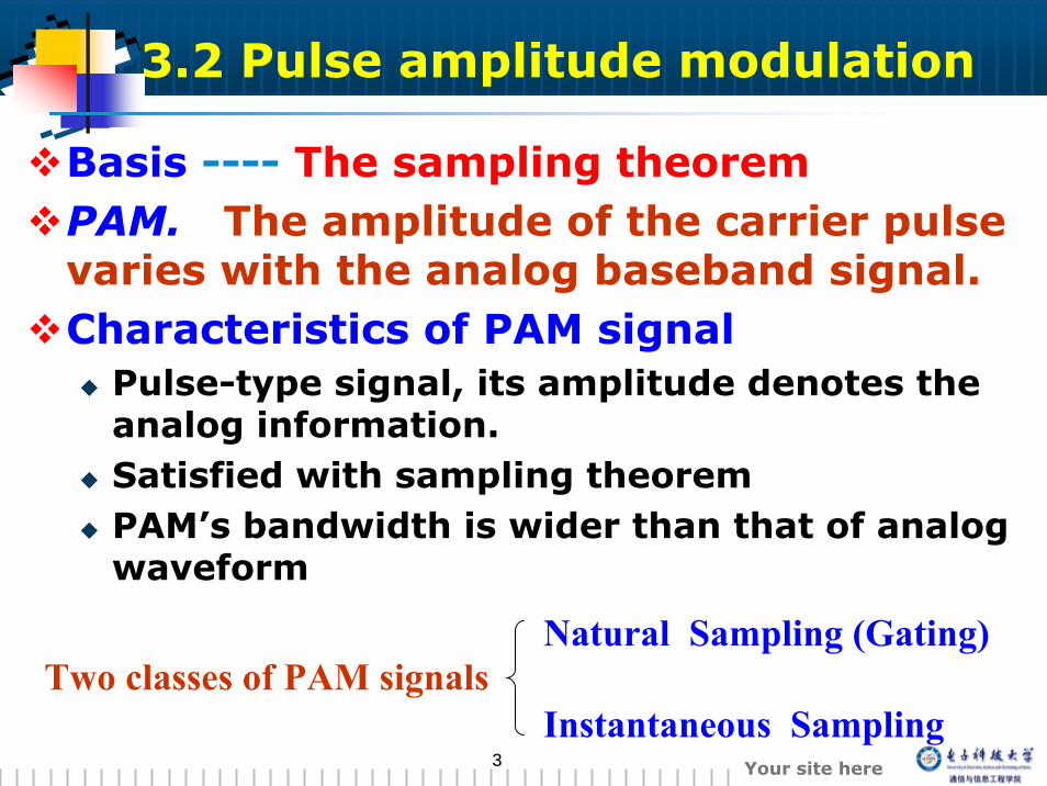
Basis ---- The sampling theoremPAM. The amplitude of the carrier pulse varies with the analog baseband signal.Characteristics of PAM signal
Pulse-type signal, its amplitude denotes the analog information.Satisfied with sampling theoremPAM’s bandwidth is wider than that of analog waveform
Two classes of PAM signalsNatural Sampling (Gating)
Instantaneous Sampling
44 Your site here
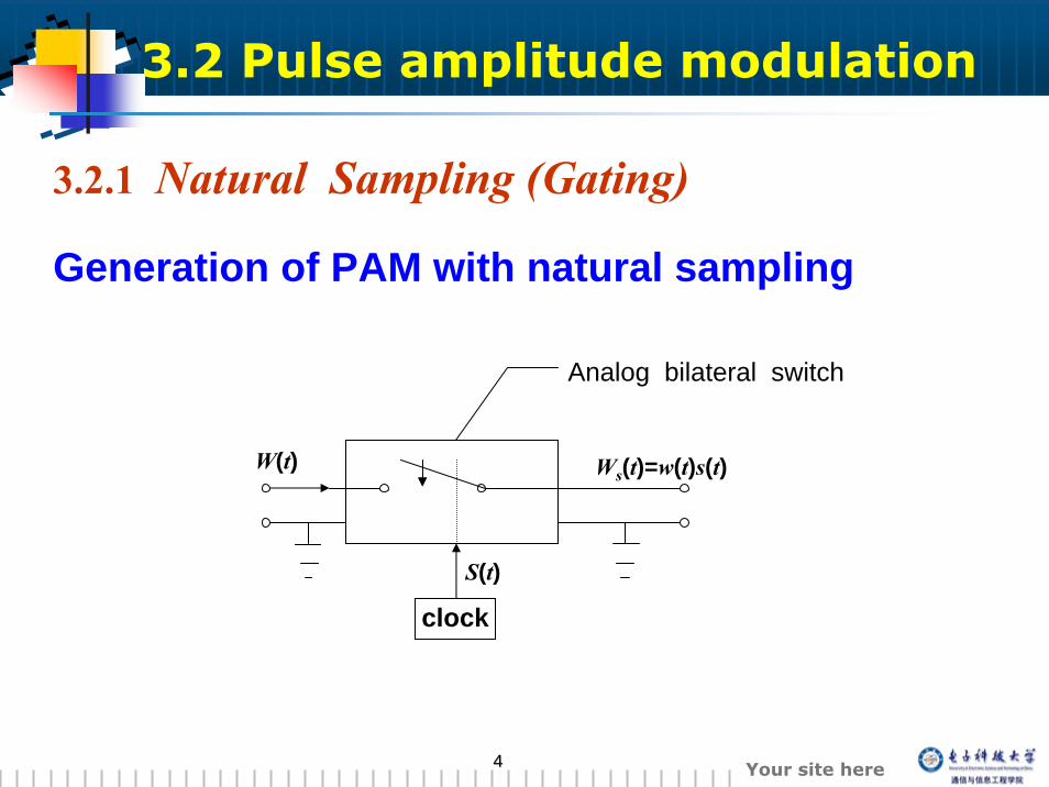
3.2.1 Natural Sampling (Gating)
clock
S(t)
Analog bilateral switch
Ws(t)=w(t)s(t)W(t)
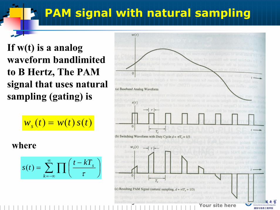
Generation of PAM with natural sampling
3.2 Pulse amplitude modulation
55 Your site here
PAM signal with natural sampling
)()()( tstwtws =
If w(t) is a analog waveform bandlimitedto B Hertz, The PAM signal that uses natural sampling (gating) is
where
∑ ∏∞
−∞=⎟⎠⎞
⎜⎝⎛ −
=k
skTttsτ
)(
66 Your site here
Spectrum of PAM waveform
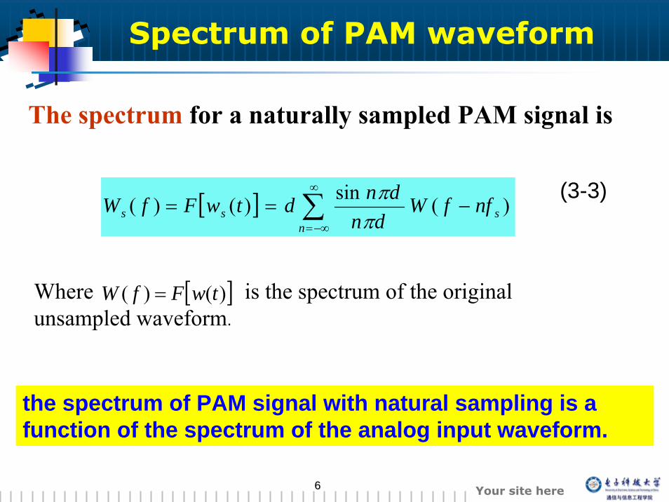
[ ] )(sin)()( sn
ss nffWdn
dndtwFfW −== ∑∞
−∞= ππ
The spectrum for a naturally sampled PAM signal is
Where is the spectrum of the original unsampled waveform.
[ ])()( twFfW =
the spectrum of PAM signal with natural sampling is a function of the spectrum of the analog input waveform.
(3-3)
77 Your site here
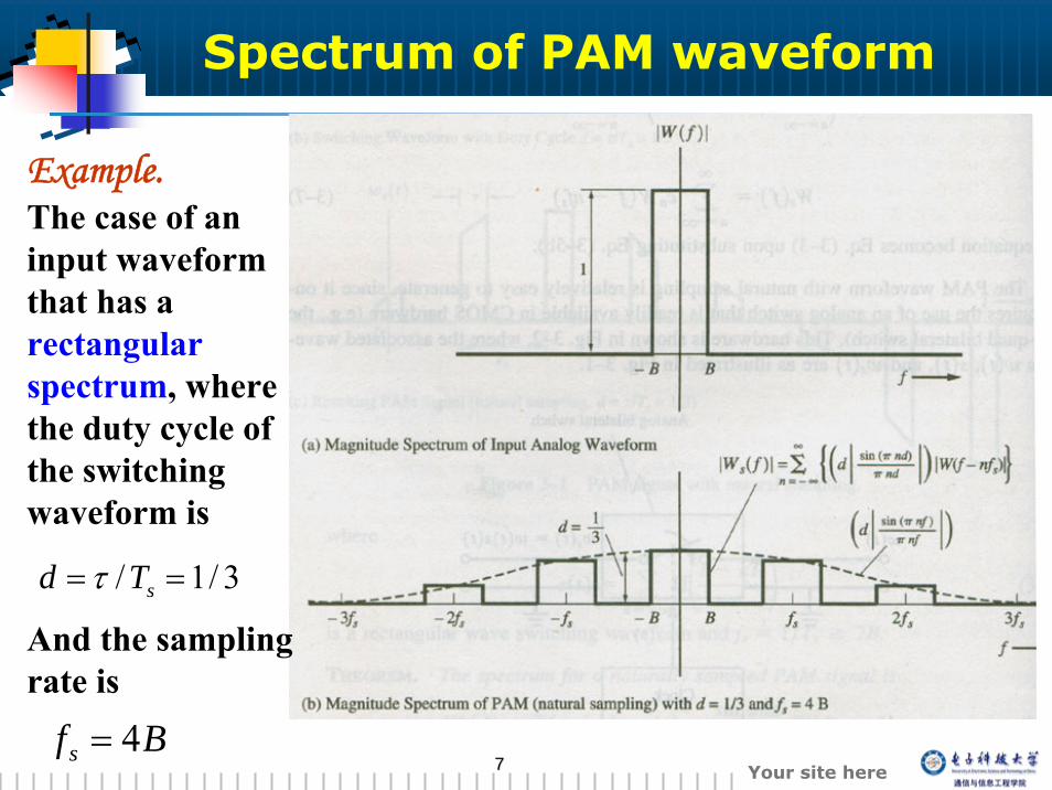
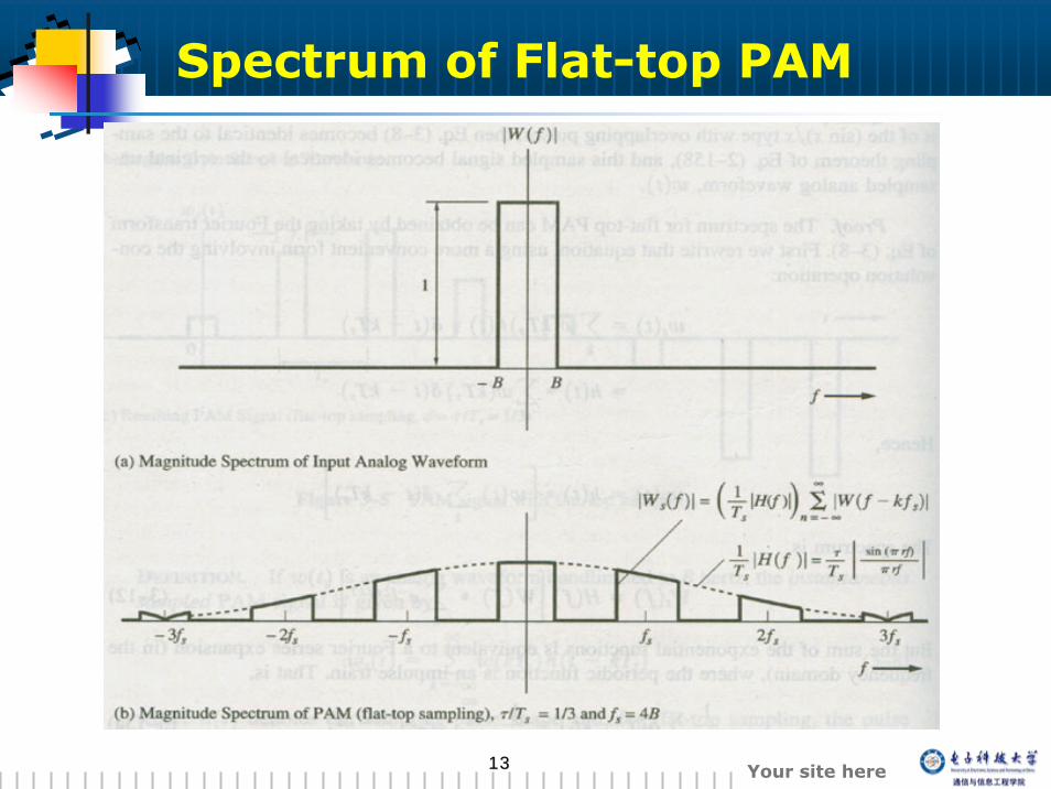
3/1/ == sTd τ
Example.The case of an input waveform that has a rectangular spectrum, where the duty cycle of the switching waveform is
And the sampling rate is
Bfs 4=
Spectrum of PAM waveform
88 Your site here
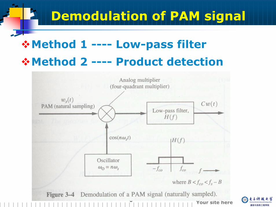
Demodulation of PAM signal
Method 1 ---- Low-pass filter
Method 2 ---- Product detection
99 Your site here
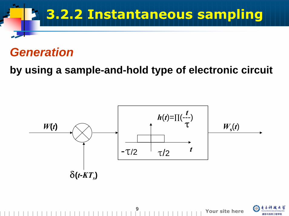
3.2.2 Instantaneous sampling
W(t)
-τ/2 τ/2 t
τh(t)=∏(---)t
Ws(t)
Generation by using a sample-and-hold type of electronic circuit
δ(t-KTs)

1010 Your site here
Instantaneous sampled PAM
Characteristic
At t=kTs, the sampling values w(kTs) determine the amplitude of the flat-top rectangular pulses.
1111 Your site here
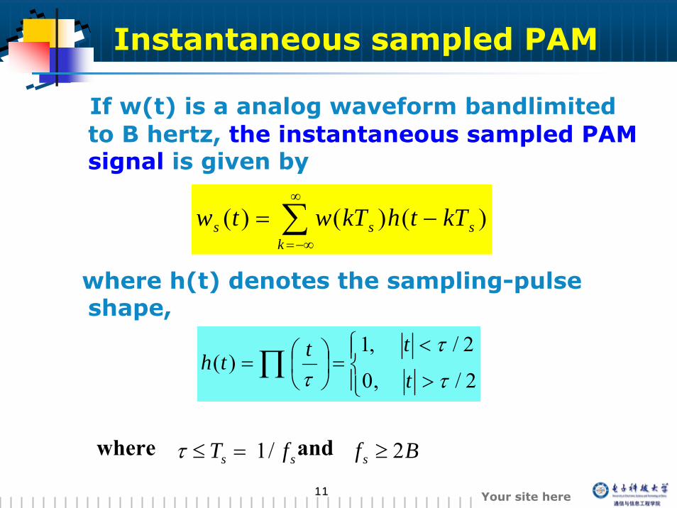
If w(t) is a analog waveform bandlimitedto B hertz, the instantaneous sampled PAM signal is given by
where h(t) denotes the sampling-pulse shape,
∑∞
−∞=
−=k
sss kTthkTwtw )()()(
⎪⎩
⎪⎨⎧
>
<=⎟
⎠⎞
⎜⎝⎛= ∏ 2/,0
2/,1)(
τ
τ
τ t
ttth
BffT sss 2/1 ≥=≤τwhere and
Instantaneous sampled PAM
1212 Your site here
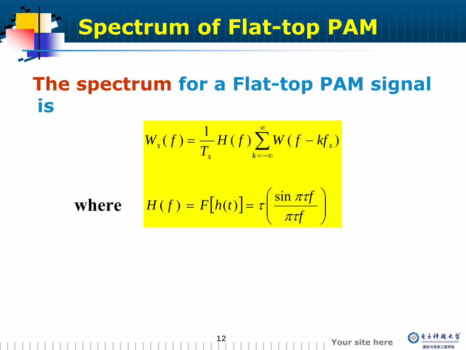
Spectrum of Flat-top PAM
The spectrum for a Flat-top PAM signal is
[ ] ⎟⎟⎠
⎞⎜⎜⎝
⎛==
−= ∑∞
−∞=
ffthFfH
kffWfHT
fWk
ss
s
πτπττ sin)()(
)()(1)(
where
1313 Your site here
Spectrum of Flat-top PAM
1414 Your site here
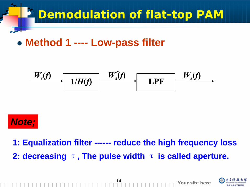
Ws(f) Ws(f)´1/H(f) LPFWs(f)
Note;
1: Equalization filter ------ reduce the high frequency loss2: decreasing τ, The pulse width τ is called aperture.
Demodulation of flat-top PAM
Method 1 ---- Low-pass filter
1515 Your site here
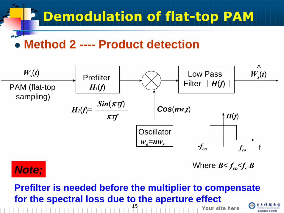
Prefilter is needed before the multiplier to compensate for the spectral loss due to the aperture effect
Note;
Method 2 ---- Product detection
Ws(t)
PAM (flat-topsampling)
PrefilterH1(f)
Cos(nwst)
Oscillatorwo=nws
Low PassFilter |H(f)|
Ws(t)^
H1(f)= Sin(πτf)πτf
fco-fco f
H(f)
Where B< fco<fs-B
Demodulation of flat-top PAM
1616 Your site here
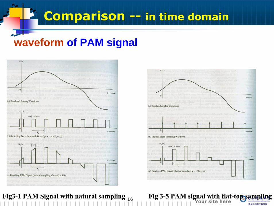
Comparison -- in time domain
Fig3-1 PAM Signal with natural sampling Fig 3-5 PAM signal with flat-top sampling
waveform of PAM signal
1717 Your site here
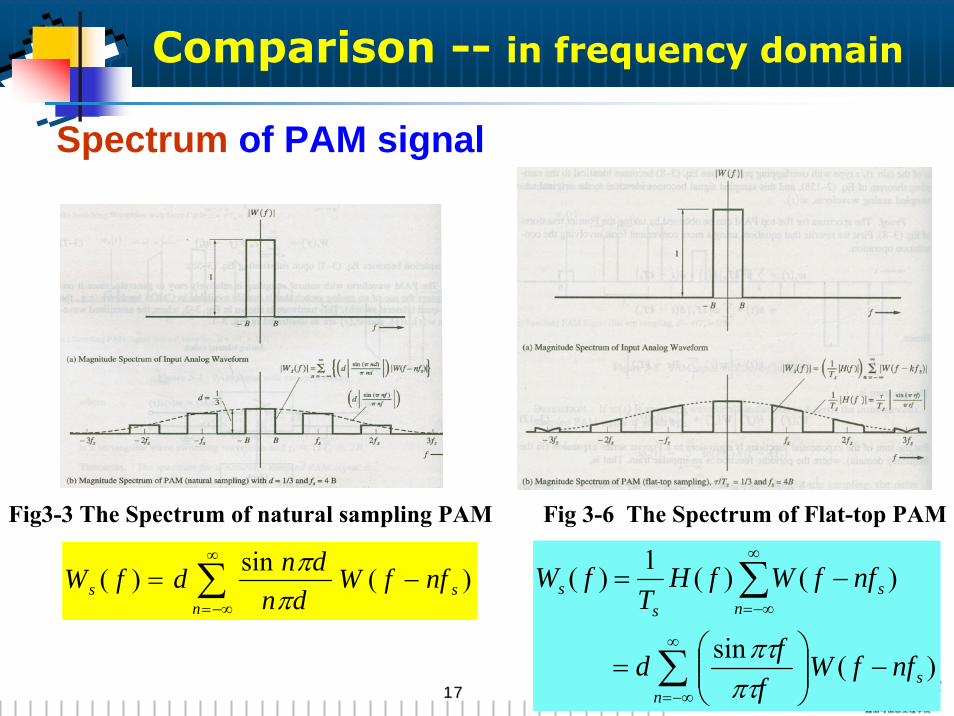
Comparison -- in frequency domain
)(sin)( sn
s nffWdn
dndfW −= ∑∞
−∞= ππ
Spectrum of PAM signal
Fig3-3 The Spectrum of natural sampling PAM Fig 3-6 The Spectrum of Flat-top PAM
∑
∑∞
−∞=
∞
−∞=
−⎟⎟⎠
⎞⎜⎜⎝
⎛=
−=
ns
ns
ss
nffWf
fd
nffWfHT
fW
)(sin
)()(1)(
πτπτ
1818 Your site here
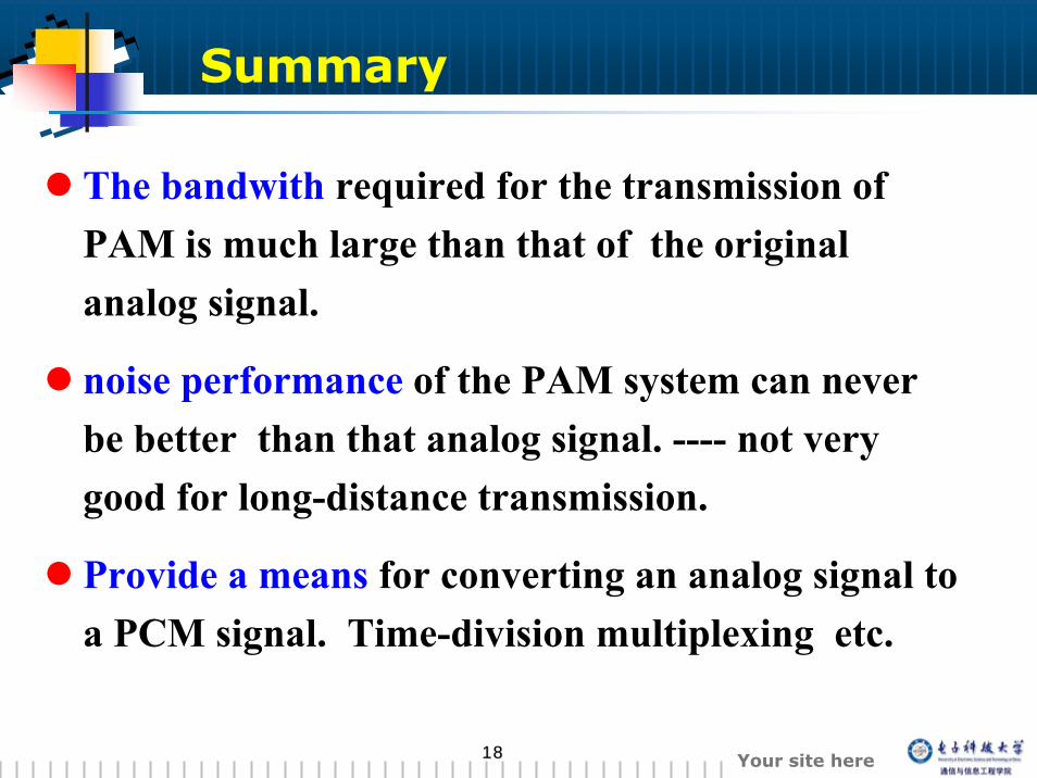
The bandwith required for the transmission of PAM is much large than that of the original analog signal.
noise performance of the PAM system can never be better than that analog signal. ---- not very good for long-distance transmission.
Provide a means for converting an analog signal to a PCM signal. Time-division multiplexing etc.
Summary

1919 Your site here
3.3 Pulse code modulation
2020 Your site here
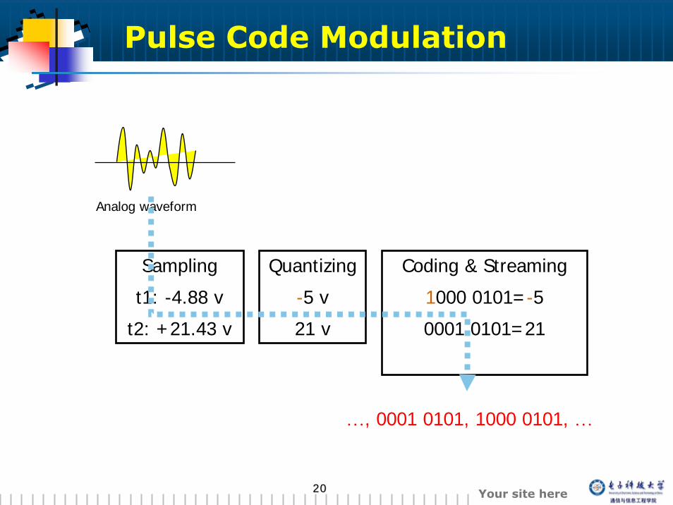
Coding & Streaming
1000 0101=-5
0001 0101=21
Pulse Code Modulation
Sampling
t1: -4.88 v
t2: +21.43 v
Analog waveform
Quantizing
-5 v
21 v
…, 0001 0101, 1000 0101, …
2121 Your site here
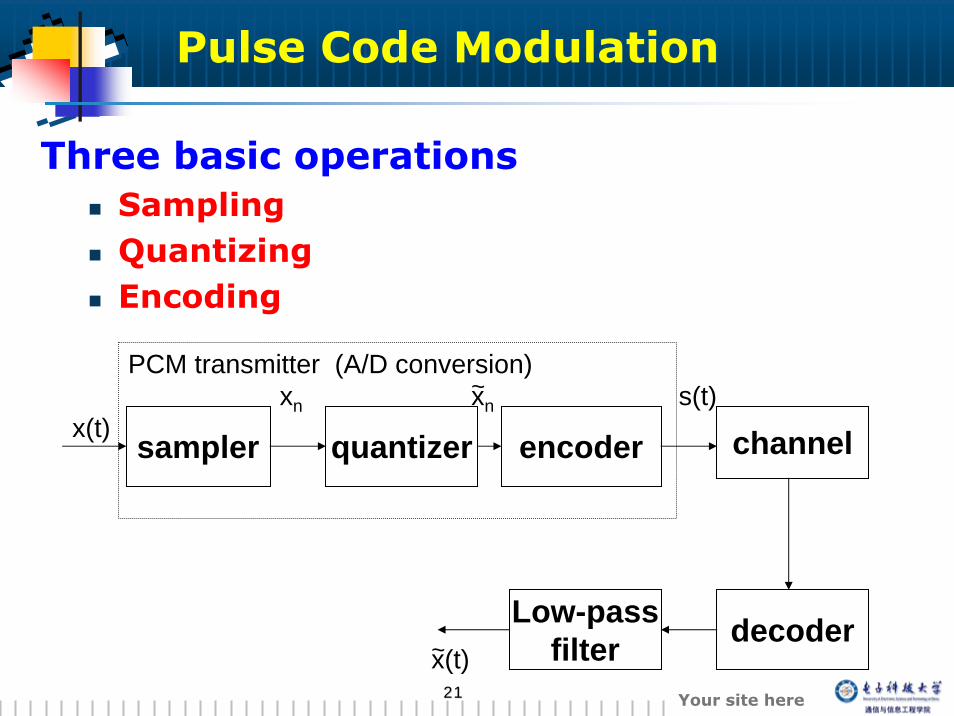
sampler quantizer encoder channel
Low-passfilter decoder
x(t)xn
x(t)
PCM transmitter (A/D conversion)
~
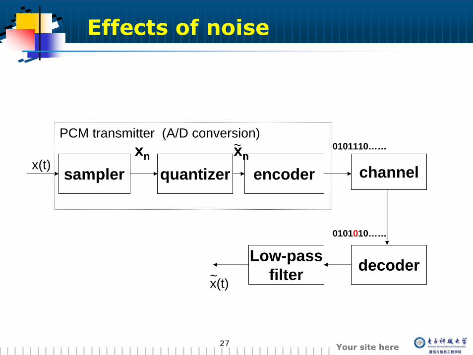
Three basic operationsSamplingQuantizingEncoding
xn~ s(t)
Pulse Code Modulation
2222 Your site here
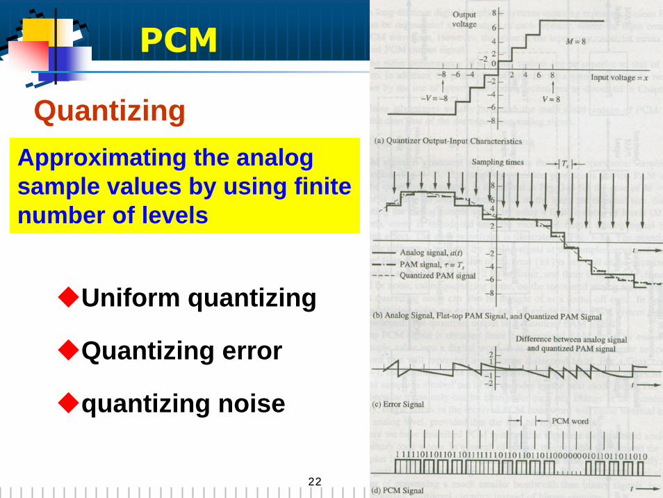
QuantizingApproximating the analog sample values by using finite number of levels
Uniform quantizing
Quantizing error
quantizing noise
PCM
2323 Your site here
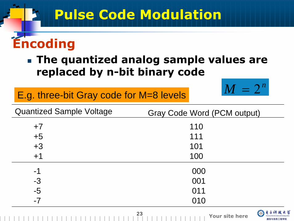
EncodingThe quantized analog sample values are replaced by n-bit binary code
Quantized Sample Voltage Gray Code Word (PCM output)+7 110+5 111+3 101+1 100
-1 000-3 001-5 011-7 010
E.g. three-bit Gray code for M=8 levelsnM 2=
Pulse Code Modulation
2424 Your site here
Bandwidth of PCM signals
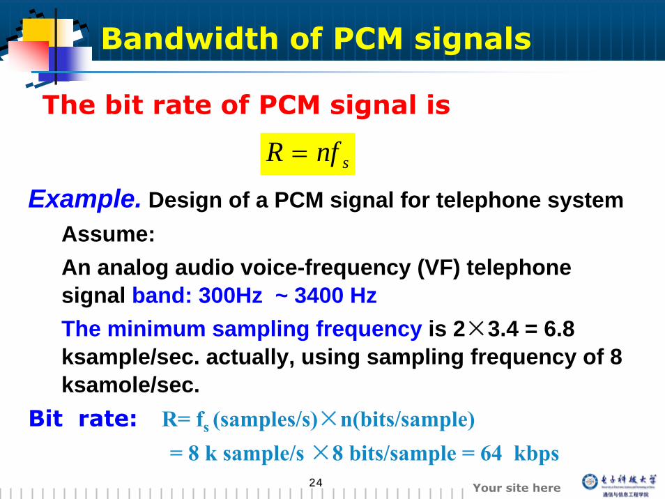
The bit rate of PCM signal is
snfR =
Bit rate: R= fs (samples/s)×n(bits/sample)= 8 k sample/s ×8 bits/sample = 64 kbps
Example. Design of a PCM signal for telephone systemAssume: An analog audio voice-frequency (VF) telephone signal band: 300Hz ~ 3400 Hz The minimum sampling frequency is 2×3.4 = 6.8 ksample/sec. actually, using sampling frequency of 8 ksamole/sec.
2525 Your site here
For rectangular pulse, the first null bandwidth is
Example. the result for the case of the minimum sampling:
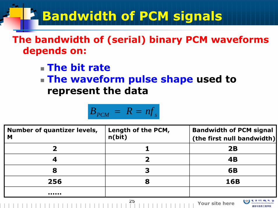
The bandwidth of (serial) binary PCM waveforms depends on:
The bit rateThe waveform pulse shape used to represent the data
sPCM nfRB ==
Number of quantizer levels, M
Length of the PCM, n(bit)
Bandwidth of PCM signal(the first null bandwidth)
2 1 2B
4 2 4B
8 3 6B
256 8 16B
……
Bandwidth of PCM signals
2626 Your site here
Effects of noise
Two main effects produce noise or distortion:
Bit errors in the recovered PCM signal . (channel noise, improper channel filtering, ISI etc. )
Quantizing noise that is caused by the M-step quantized at PCM transmitter
2727 Your site here
sampler quantizer encoder channel
Low-passfilter decoder
x(t)xn
x(t)
PCM transmitter (A/D conversion)
~
0101110……
0101010……
xn~
Effects of noise
2828 Your site here
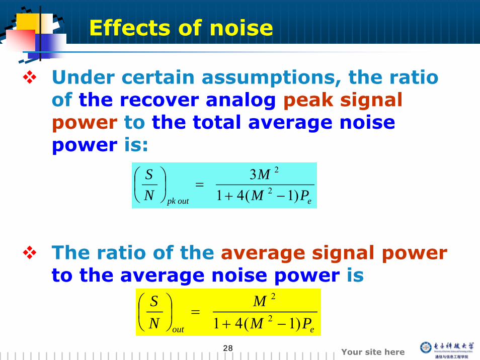
Under certain assumptions, the ratio of the recover analog peak signal power to the total average noise power is:
The ratio of the average signal powerto the average noise power is
eoutpk PMM
NS
)1(413
2
2
−+=⎟
⎠⎞
⎜⎝⎛
eout PMM
NS
)1(41 2
2
−+=⎟
⎠⎞
⎜⎝⎛
Effects of noise
2929 Your site here
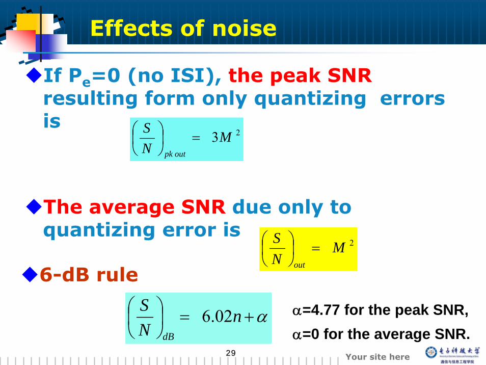
If Pe=0 (no ISI), the peak SNRresulting form only quantizing errors is
The average SNR due only to quantizing error is
23MNS
outpk
=⎟⎠⎞
⎜⎝⎛
2MNS
out
=⎟⎠⎞
⎜⎝⎛
α+=⎟⎠⎞
⎜⎝⎛ n
NS
dB
02.6
6-dB rule
α=4.77 for the peak SNR,α=0 for the average SNR.
Effects of noise
3030 Your site here
This equation points out the significant performance characteristic for PCM:
An additional 6-dB improvement in SNR is obtained for each bit added to the PCM word.
Assumptions:
① No bit errors② the input signal level is large enough to range over a significant number of quantizing levels
Effects of noise
3131 Your site here
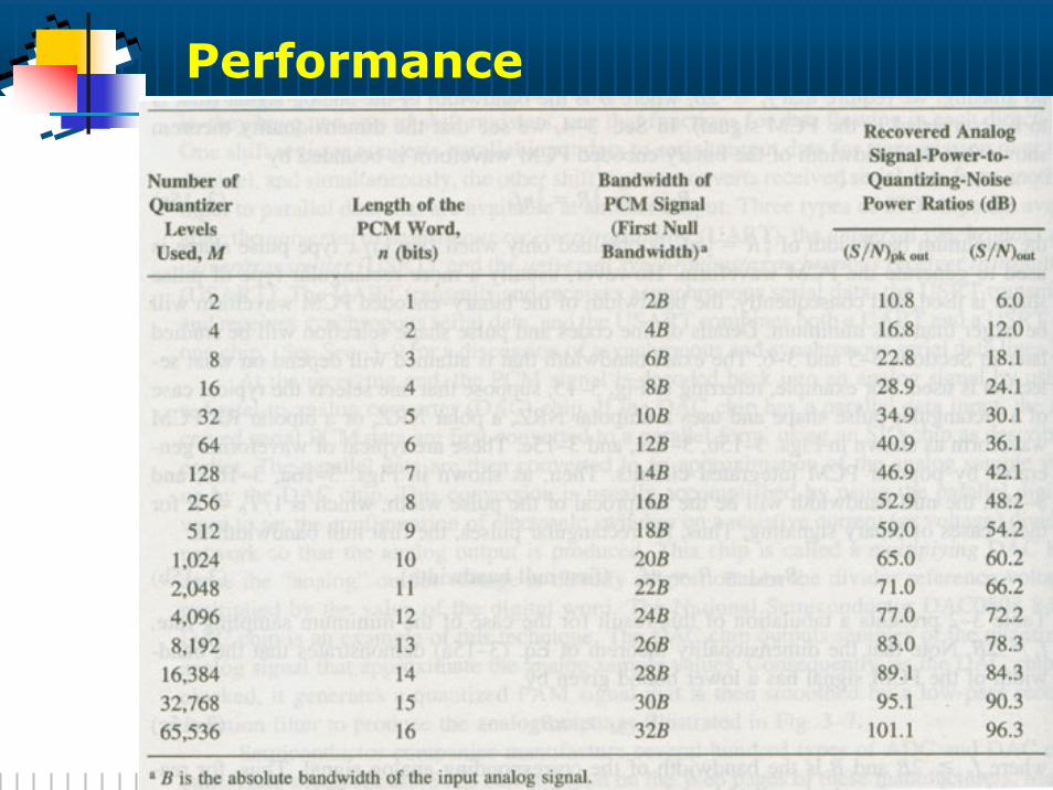
Performance
3232 Your site here
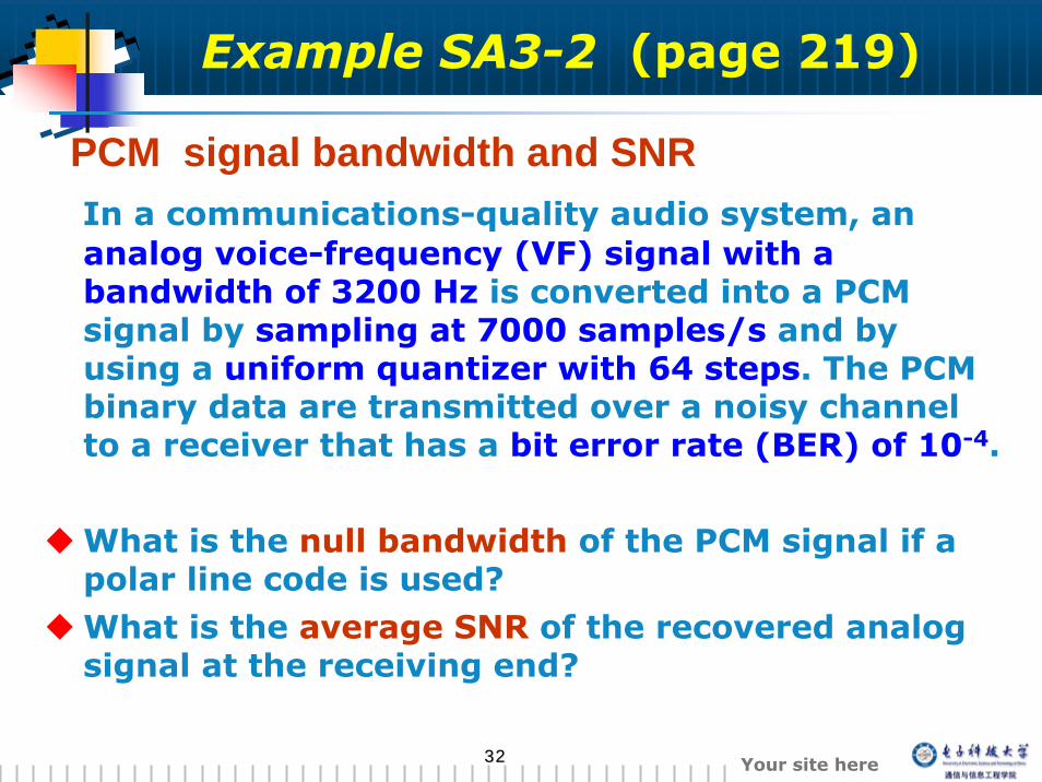
Example SA3-2 (page 219)
In a communications-quality audio system, an analog voice-frequency (VF) signal with a bandwidth of 3200 Hz is converted into a PCM signal by sampling at 7000 samples/s and by using a uniform quantizer with 64 steps. The PCM binary data are transmitted over a noisy channel to a receiver that has a bit error rate (BER) of 10-4.
What is the null bandwidth of the PCM signal if a polar line code is used?What is the average SNR of the recovered analog signal at the receiving end?
PCM signal bandwidth and SNR
3333 Your site here
Nonuniform Quantizing
Characteristic voice analog signal
Nonuniform amplitude distributionThe granular quantizing noise will be a serious problem if uniform quantizing is used.
Solution: nonuiform quantizing
Nouniform Quantizing: a variable step size is used
3434 Your site here
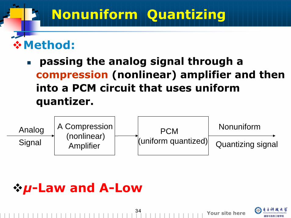
Method:passing the analog signal through a compression (nonlinear) amplifier and then into a PCM circuit that uses uniform quantizer.
μ-Law and A-Low
AnalogSignal
A Compression(nonlinear)Amplifier
PCM(uniform quantized)
Nonuniform
Quantizing signal
Nonuniform Quantizing
3535 Your site here
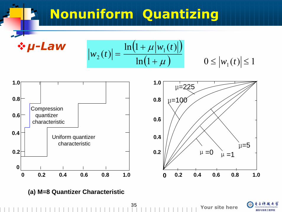
μ-Law ( )( )μμ+
+=
1ln)(1ln
)( 12
twtw
Compressionquantizer
characteristic
Uniform quantizercharacteristic
(a) M=8 Quantizer Characteristic
00
0.2 0.4 0.6 0.8 1.0
0.2
0.4
0.6
0.8
1.0
0 0.2 0.4 0.6 0.8 1.0
0.2
0.4
0.6
0.8
1.0
μ=0 μ=1μ=5
μ=100
μ=225
1)(0 1 ≤≤ tw
Nonuniform Quantizing
3636 Your site here
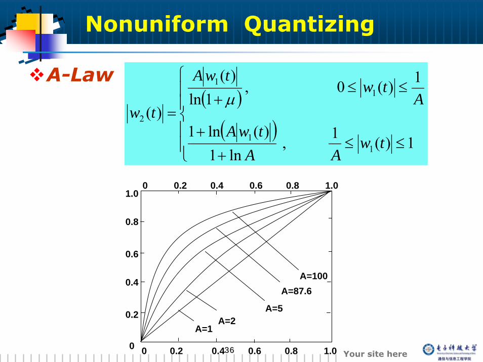
A-Law( )
( )⎪⎪
⎩
⎪⎪
⎨
⎧
≤≤+
+
≤≤+
=
1)(1,ln1
)(ln1
1)(0,1ln
)(
)(
11
11
2
twAA
twA
Atw
twA
twμ
0 0.2 0.4 0.6 0.8 1.0
0 0.2 0.4 0.6 0.8 1.0
0
0.2
0.4
0.6
0.8
1.0
A=1A=2
A=5
A=87.6A=100
Nonuniform Quantizing
3737 Your site here
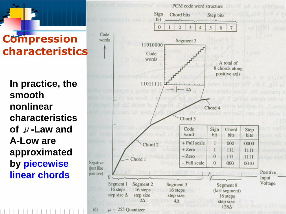
In practice, the smooth nonlinear characteristics of μ-Law and A-Low are approximated by piecewise linear chords
Compression characteristics
3838 Your site here
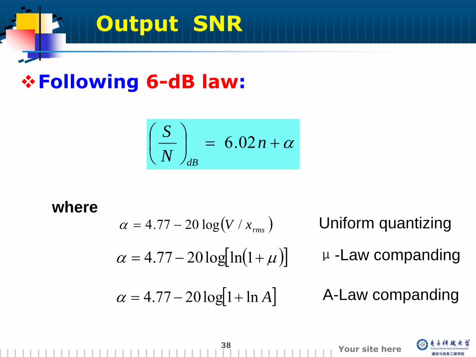
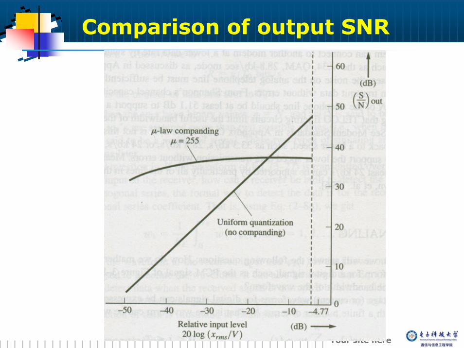
Output SNR
Following 6-dB law:
α+=⎟⎠⎞
⎜⎝⎛ n
NS
dB
02.6
( )rmsxV /log2077.4 −=α
( )[ ]μα +−= 1lnlog2077.4
[ ]Aln1log2077.4 +−=α
whereUniform quantizing
μ-Law companding
A-Law companding
3939 Your site here
Comparison of output SNR
4040 Your site here
3.4 Digital signaling
4141 Your site here
Introduction
Baseband signalsthe signals involved in the analog-to-digital conversion
Bandpass signalsThe signals produced by using basebanddigital signals to modulate a carrier.
4242 Your site here
How do we mathematically represent the waveformfor a digital signal?
How do we estimate the bandwidth of the waveform?
In this section, we will answer the following questions:
Introduction
4343 Your site here
Vector representation
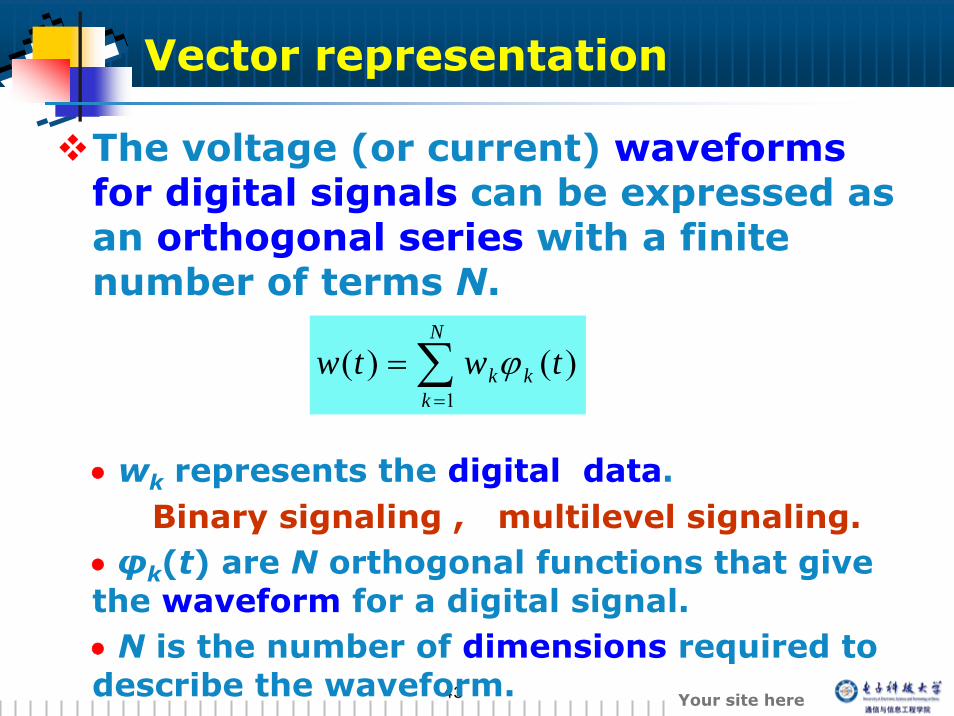
The voltage (or current) waveforms for digital signals can be expressed as an orthogonal series with a finite number of terms N.
• wk represents the digital data.Binary signaling , multilevel signaling.
• φk(t) are N orthogonal functions that give the waveform for a digital signal. • N is the number of dimensions required to describe the waveform.
∑=
=N
kkk twtw
1)()( ϕ
4444 Your site here
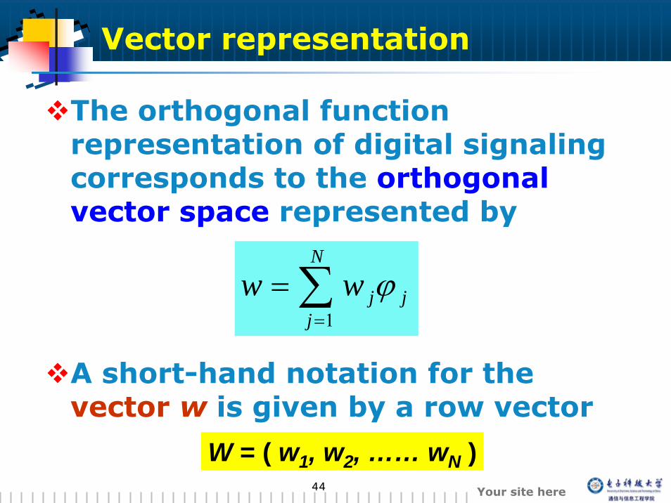
The orthogonal function representation of digital signaling corresponds to the orthogonal vector space represented by
A short-hand notation for the vector w is given by a row vector
∑=
=N
jjjww
1ϕ
W = ( w1, w2, …… wN )
Vector representation
4545 Your site here
baud rate and bit rate
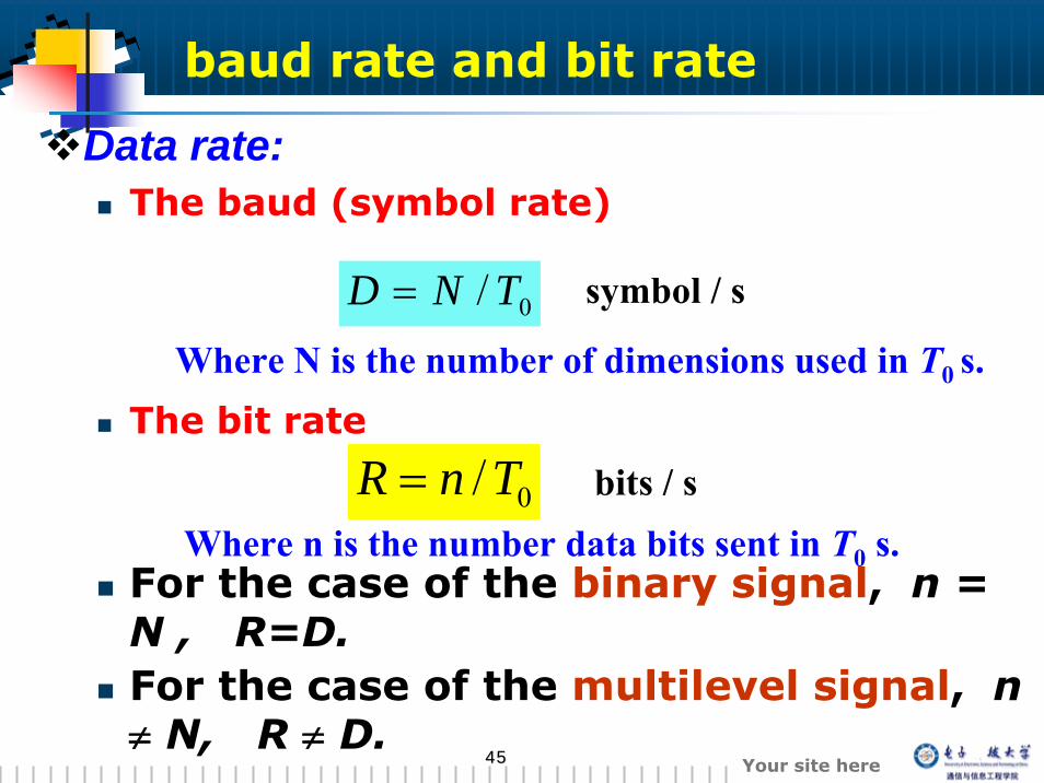
Data rate:The baud (symbol rate)
The bit rate
For the case of the binary signal, n = N , R=D.For the case of the multilevel signal, n ≠ N, R ≠ D.
0/ TND =
0/TnR =
symbol / s
bits / s
Where N is the number of dimensions used in T0 s.
Where n is the number data bits sent in T0 s.
4646 Your site here
Bandwidth estimation
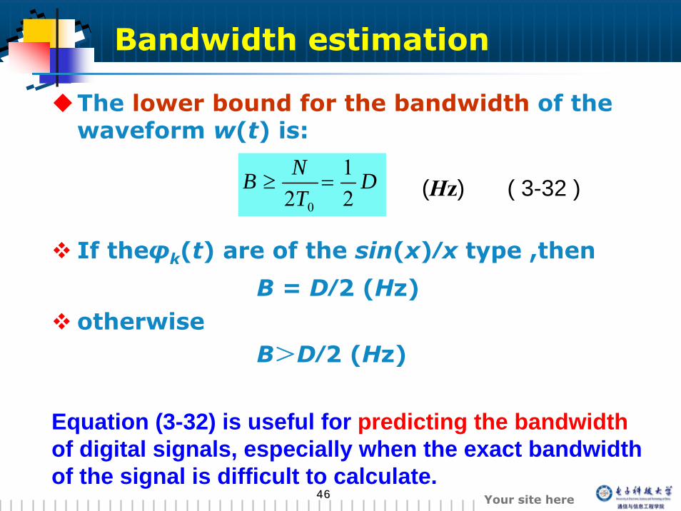
The lower bound for the bandwidth of the waveform w(t) is:
If theφk(t) are of the sin(x)⁄x type ,then
B = D⁄2 (Hz)otherwise
B>D⁄2 (Hz)
DTNB
21
2 0
=≥
Equation (3-32) is useful for predicting the bandwidthof digital signals, especially when the exact bandwidth of the signal is difficult to calculate.
( 3-32 )(Hz)
4747 Your site here
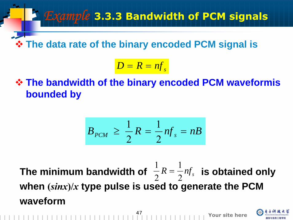
Example 3.3.3 Bandwidth of PCM signals
The data rate of the binary encoded PCM signal is
The bandwidth of the binary encoded PCM waveformisbounded by
nBnfRB sPCM ==≥21
21
snfRD ==
The minimum bandwidth of is obtained only when (sinx)/x type pulse is used to generate the PCM waveform
snfR21
21
=
4848 Your site here
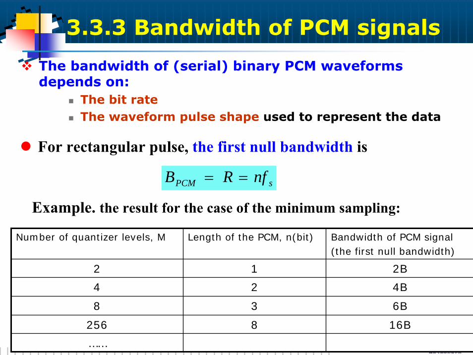
For rectangular pulse, the first null bandwidth is
Example. the result for the case of the minimum sampling:
3.3.3 Bandwidth of PCM signals
The bandwidth of (serial) binary PCM waveforms depends on:
The bit rateThe waveform pulse shape used to represent the data
sPCM nfRB ==
Number of quantizer levels, M Length of the PCM, n(bit) Bandwidth of PCM signal(the first null bandwidth)
2 1 2B
4 2 4B
8 3 6B
256 8 16B
……
4949 Your site here
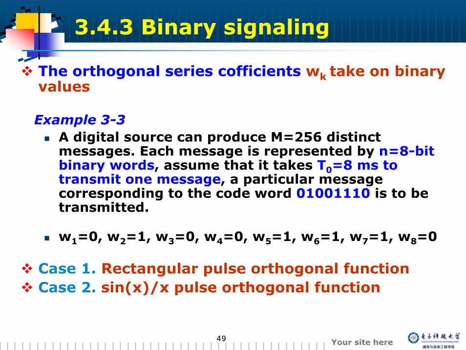
3.4.3 Binary signaling
The orthogonal series cofficients wk take on binary values
Example 3-3A digital source can produce M=256 distinct messages. Each message is represented by n=8-bit binary words, assume that it takes T0=8 ms to transmit one message, a particular message corresponding to the code word 01001110 is to be transmitted.
w1=0, w2=1, w3=0, w4=0, w5=1, w6=1, w7=1, w8=0
Case 1. Rectangular pulse orthogonal functionCase 2. sin(x)/x pulse orthogonal function
5050 Your site here
1.5
1
0.5
0
-0.5 0 1 2 3 4 5 6 7 8t(ms)
1.5
1
0.5
0
-0.5 0 1 2 3 4 5 6 7 8
t(ms)
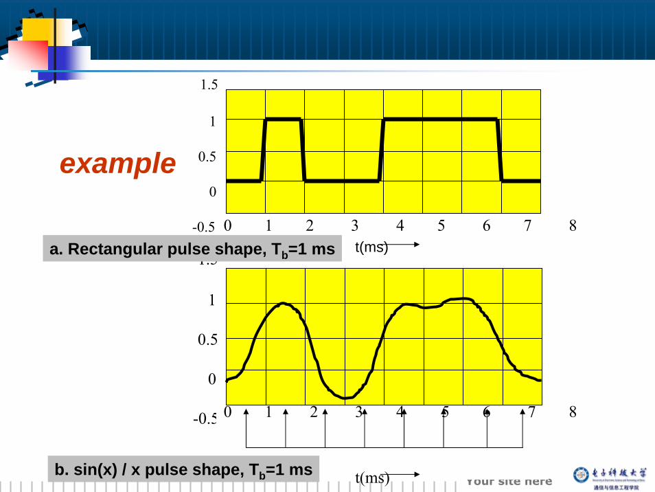
example
a. Rectangular pulse shape, Tb=1 ms
b. sin(x) / x pulse shape, Tb=1 ms
5151 Your site here
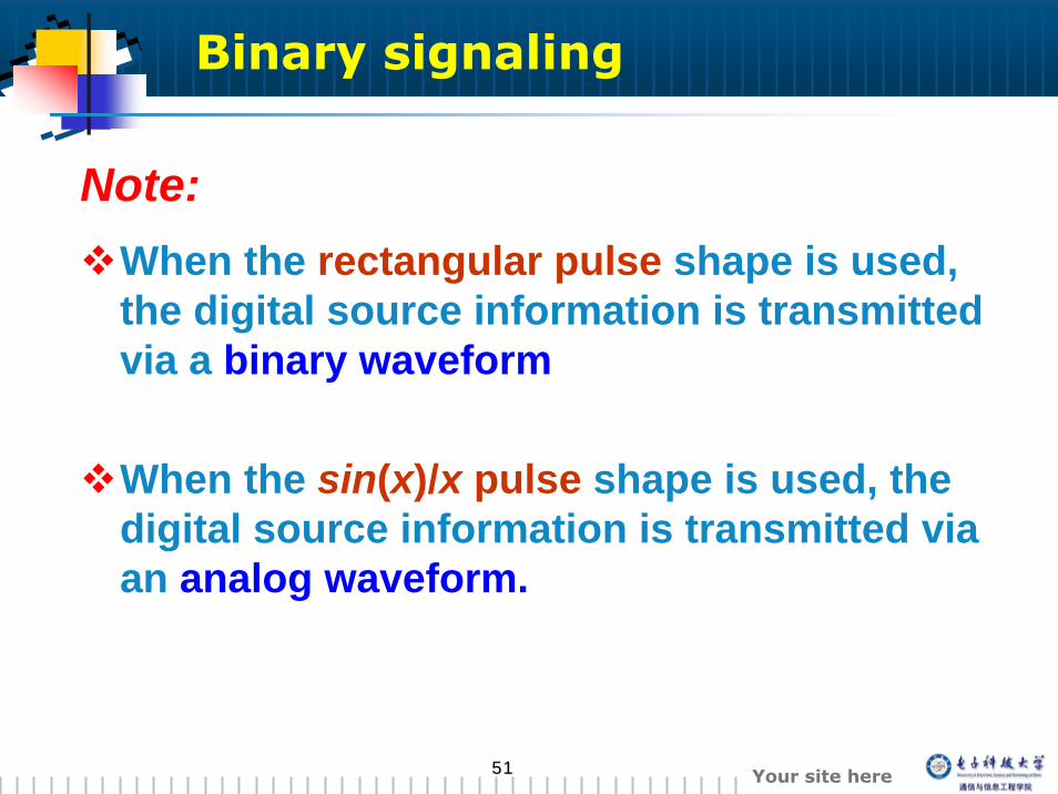
Binary signaling
When the rectangular pulse shape is used, the digital source information is transmitted via a binary waveform
When the sin(x)/x pulse shape is used, the digital source information is transmitted via an analog waveform.
Note:
5252 Your site here
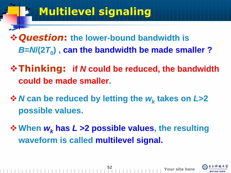
Multilevel signaling
Question: the lower-bound bandwidth is B=N/(2T0) , can the bandwidth be made smaller ?
Thinking: if N could be reduced, the bandwidth could be made smaller.
N can be reduced by letting the wk takes on L>2 possible values.
When wk has L >2 possible values, the resulting waveform is called multilevel signal.
5353 Your site here
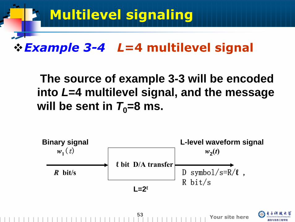
Example 3-4 L=4 multilevel signal
The source of example 3-3 will be encoded into L=4 multilevel signal, and the message will be sent in T0=8 ms.
ℓ bit D/A transferR bit/s D symbol/s=R/ℓ ,
R bit/s
Binary signal w1(t)
L-level waveform signalw2(t)
L=2ℓ
Multilevel signaling
5454 Your site here
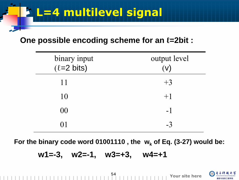
One possible encoding scheme for an ℓ=2bit :
binary input(ℓ=2 bits)
11 +3
10 +1
00 -1
01 -3
output level(v)
For the binary code word 01001110 , the wk of Eq. (3-27) would be:
w1=-3, w2=-1, w3=+3, w4=+1
L=4 multilevel signal
5555 Your site here
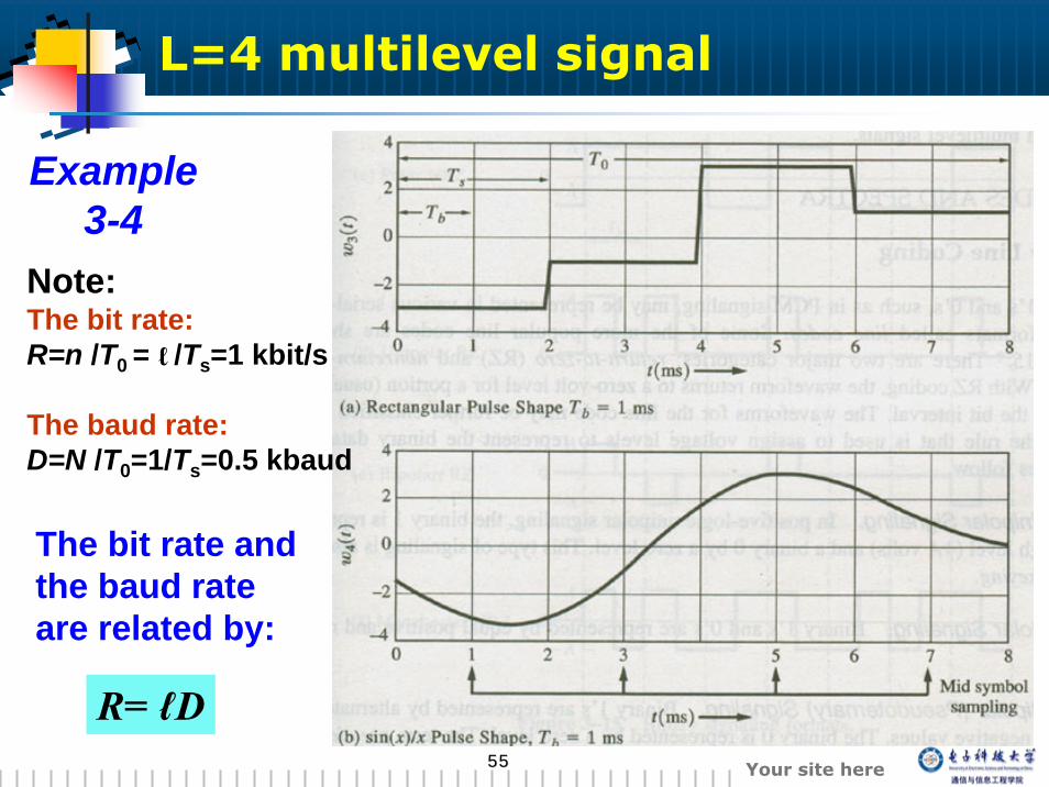
Example 3-4
Note:The bit rate:R=n /T0 = /Ts=1 kbit/s
The baud rate:D=N /T0=1/Ts=0.5 kbaud
The bit rate and the baud rate are related by:
L=4 multilevel signal
ℓ
R= ℓD
5656 Your site here
The null bandwidth of the rectangular-pulse multilevel waveform, fig. 3-14a:
B= 1/Ts = D = 500Hz
The absolute bandwidth of the sin(x)/x-pulse multilevel waveform, fig. 3-14b:
B= N/(2T0) = D/2 = 250Hz
In general, an L-level multilevel signal would have 1/ℓ the bandwidth of the corresponding binary signal, where ℓ =log2(L).
L=4 multilevel signal

5757 Your site here
3.5 Line codes and spectra
5858 Your site here
Line codes and spectra
Self-synchronizationA spectrum that is suitable for the channelLow probability of bit errorTransmission bandwidth should be as small as possibleError detection capability……
Why line codes must be used?
Properties of a line codes
5959 Your site here
classification of the Line codes
Two major categories:
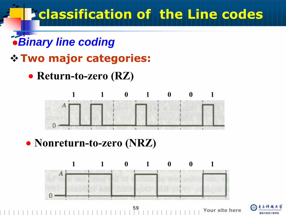
Binary line coding
• Return-to-zero (RZ)
• Nonreturn-to-zero (NRZ)
1 00101 1
1 00101 1
6060 Your site here
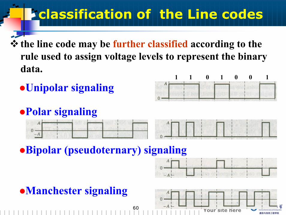
the line code may be further classified according to the rule used to assign voltage levels to represent the binary data.
Polar signaling
Bipolar (pseudoternary) signaling
Manchester signaling
Unipolar signaling1 100101
classification of the Line codes
6161 Your site here
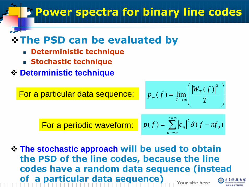
Power spectra for binary line codes
The PSD can be evaluated byDeterministic techniqueStochastic technique
Deterministic technique
The stochastic approach will be used to obtain the PSD of the line codes, because the line codes have a random data sequence (instead of a particular data sequence)
⎟⎟
⎠
⎞
⎜⎜
⎝
⎛=
∞→ TfW
fp T
Tw
2)(lim)(
∑∞=
−∞=
−=n
nn nffcfp )()( 0
2δFor a periodic waveform:
For a particular data sequence:
6262 Your site here
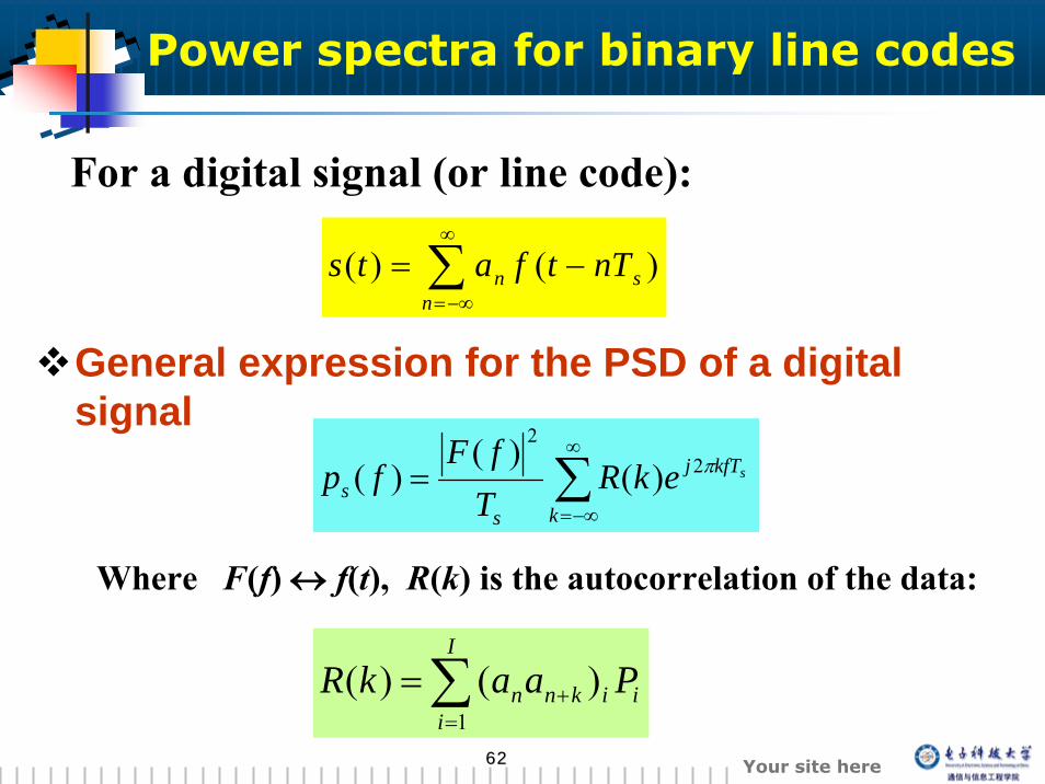
General expression for the PSD of a digital signal
∑∞
−∞=
=k
kfTj
ss
sekRTfF
fp π22
)()(
)(
∑=
+=I
iiiknn PaakR
1)()(
Where F(f) ↔ f(t), R(k) is the autocorrelation of the data:
∑∞
−∞=
−=n
sn nTtfats )()(
For a digital signal (or line code):
Power spectra for binary line codes
6363 Your site here
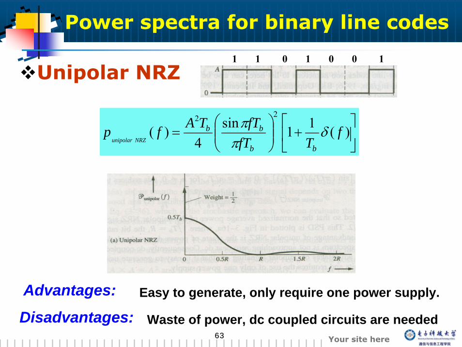
Unipolar NRZ
⎥⎦
⎤⎢⎣
⎡+⎟⎟
⎠
⎞⎜⎜⎝
⎛= )(11sin
4)(
22
fTfT
fTTAfpbb
bbNRZunipolar
δππ
Advantages:Disadvantages:
Easy to generate, only require one power supply.
Waste of power, dc coupled circuits are needed
1 100101
Power spectra for binary line codes
6464 Your site here
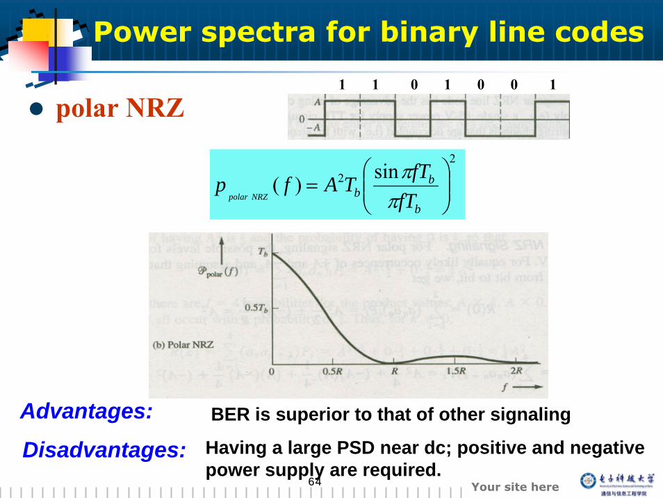
polar NRZ
22 sin)( ⎟⎟
⎠
⎞⎜⎜⎝
⎛=
b
bb fT
fTTAfpNRZpolar π
π
Advantages:Disadvantages:
BER is superior to that of other signaling
Having a large PSD near dc; positive and negative power supply are required.
1 100101
Power spectra for binary line codes
6565 Your site here
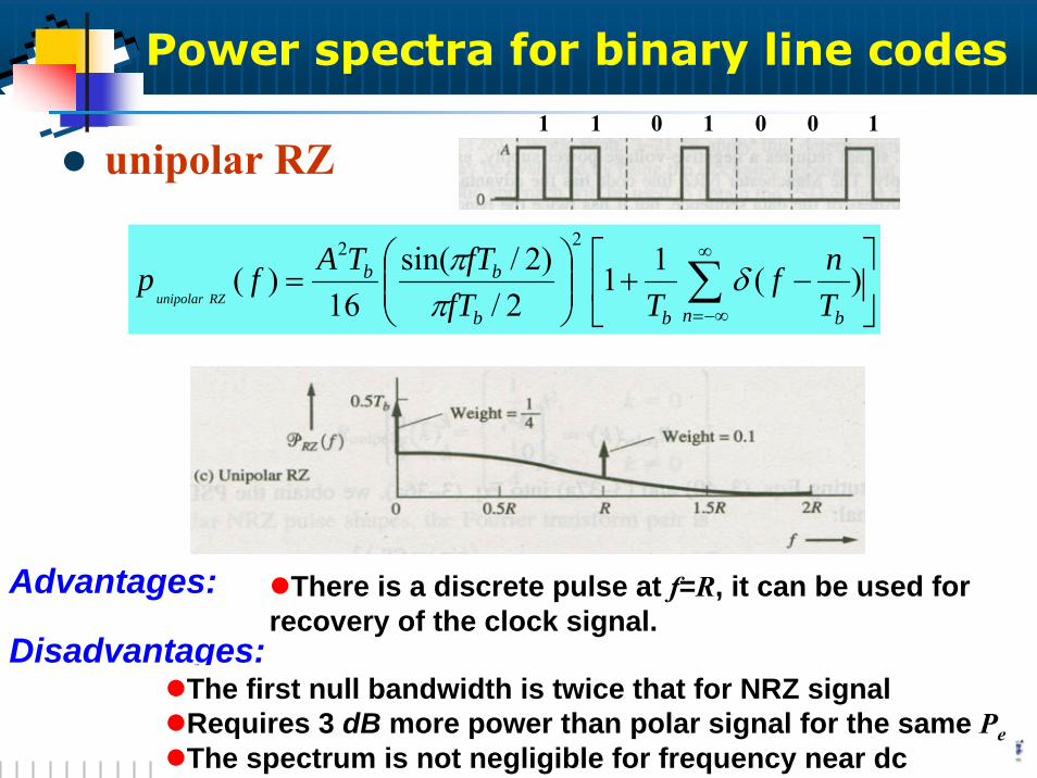
unipolar RZ
⎥⎦
⎤⎢⎣
⎡−+⎟⎟
⎠
⎞⎜⎜⎝
⎛= ∑
∞
−∞=n bbb
bb
Tnf
TfTfTTAfp
RZunipolar)(11
2/)2/sin(
16)(
22
δππ
Advantages:
Disadvantages:
There is a discrete pulse at f=R, it can be used for recovery of the clock signal.
The first null bandwidth is twice that for NRZ signalRequires 3 dB more power than polar signal for the same PeThe spectrum is not negligible for frequency near dc
1 100101
Power spectra for binary line codes
6666 Your site here
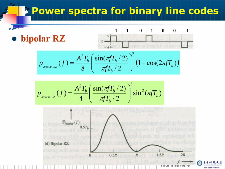
bipolar RZ
( ))2cos(12/
)2/sin(8
)(22
bb
bb fTfT
fTTAfpRZbipolar
πππ
−⎟⎟⎠
⎞⎜⎜⎝
⎛=
)(sin2/
)2/sin(4
)( 222
bb
bb fTfT
fTTAfpRZbipolar
πππ
⎟⎟⎠
⎞⎜⎜⎝
⎛=
1 100101
Power spectra for binary line codes
6767 Your site here
bipolar RZ
Advantages:
Disadvantages:
Has a spectral null at dc, so ac coupled circuit may be used.The clock signal can be easily be extracted for the bipolar
waveformHas single-error detection capabilities
The receiver has to distinguish between tree levels (+A, -A and 0)
Requires approximately 3 dB more power than polar signal for the same Pe. It has 3/2 the error of unipolar signal
Power spectra for binary line codes
6868 Your site here
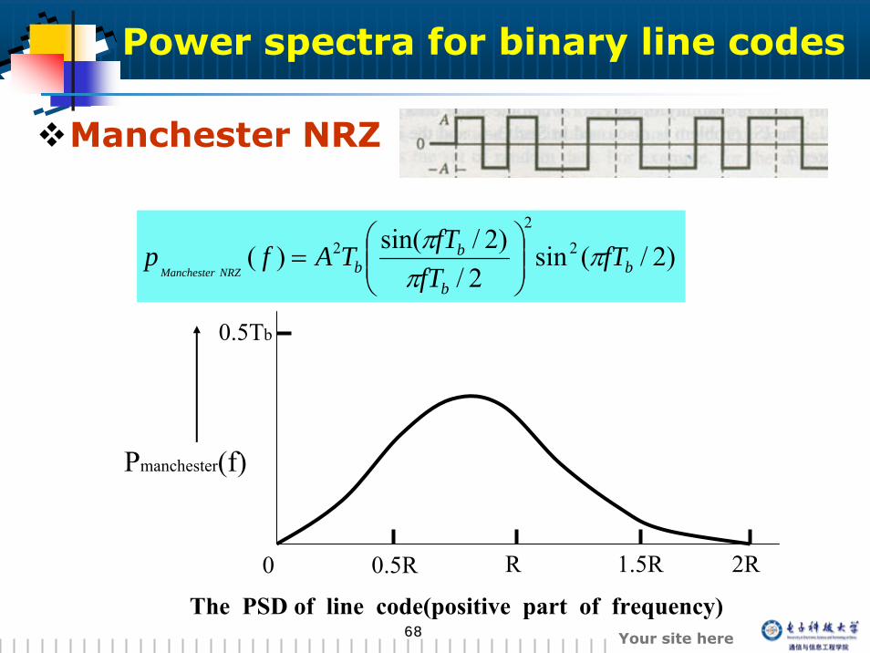
Manchester NRZ
)2/(sin2/
)2/sin()( 22
2b
b
bb fT
fTfTTAfp
NRZManchesterπ
ππ
⎟⎟⎠
⎞⎜⎜⎝
⎛=
0 0.5R R 1.5R 2R
0.5Tb
Pmanchester(f)
The PSD of line code(positive part of frequency)
Power spectra for binary line codes
6969 Your site here
Manchester NRZ
Advantages:
Disadvantages:
Has a zero dc levelA string of zeros will not cause a loss of the
clocking signal
The null bandwidth is twice that of the bipolar bandwidth
Power spectra for binary line codes
7070 Your site here
summery
The spectrum is a function of the bit pattern(via the bit autocorrelation) as well as the pulse shape.
The general result for the PSD, Eq. (3-36), is valid for multilevel as well as binary signaling.
7171 Your site here
3.5.3 Differential coding
7272 Your site here
3.5.3 Differential coding
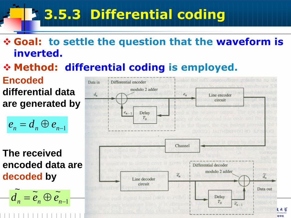
Goal: to settle the question that the waveform is inverted.Method: differential coding is employed.
1−⊕= nnn ede
1−⊕= nnn eed ~~ ~
Encodeddifferential data are generated by
The received encoded data are decoded by
7373 Your site here
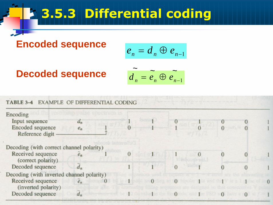
1−⊕= nnn edeEncoded sequence
Decoded sequence1−⊕= nnn eed
~~ ~
3.5.3 Differential coding
7474 Your site here
3.5.4 Eye patterns
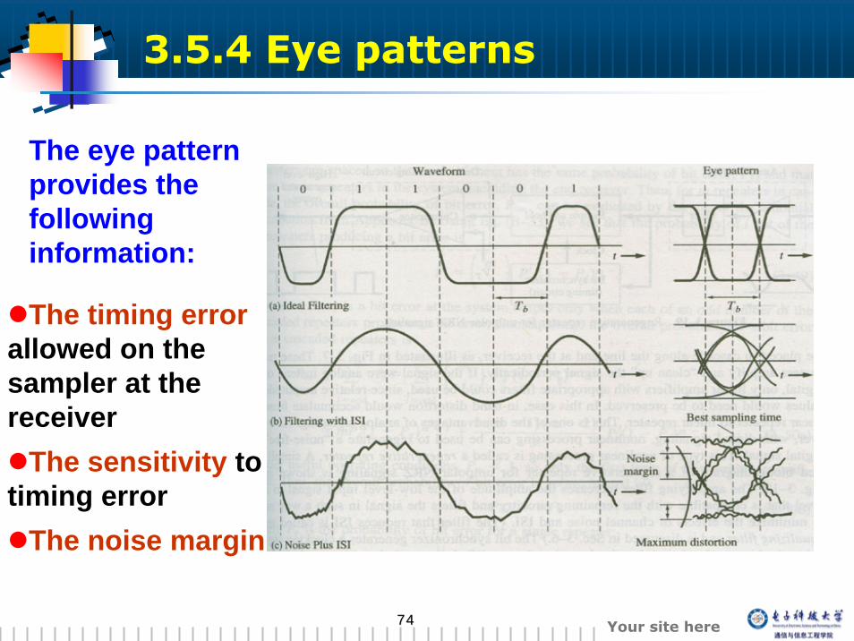
The eye pattern provides the following information:
The timing errorallowed on the sampler at the receiver
The sensitivity to timing error
The noise margin
7575 Your site here
3.5.5 Regenerative repeaters
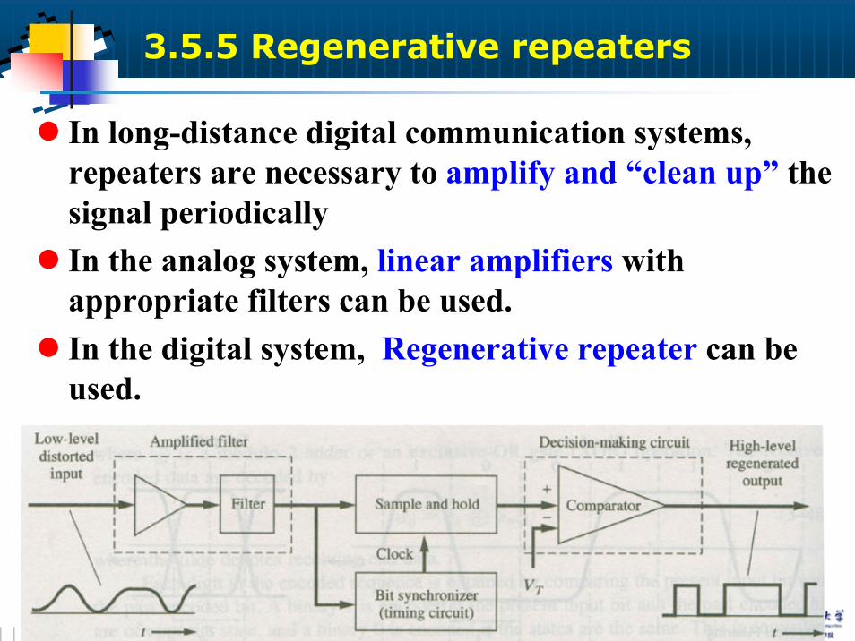
In long-distance digital communication systems, repeaters are necessary to amplify and “clean up” the signal periodicallyIn the analog system, linear amplifiers with appropriate filters can be used.In the digital system, Regenerative repeater can be used.
7676 Your site here
3.5.6 Bit synchronization
Digital communication usually need at least three types of synchronization signals:
Bit sync, to distinguish one bit interval from anotherFrame sync, to distinguish groups of dataCarrier sync. For bandpass signaling with coherent detection
Two kinds of ways to obtain synchronization signals:directly from the corrupted signalfrom a separate channel that is used only to transmit the sync. information
7777 Your site here
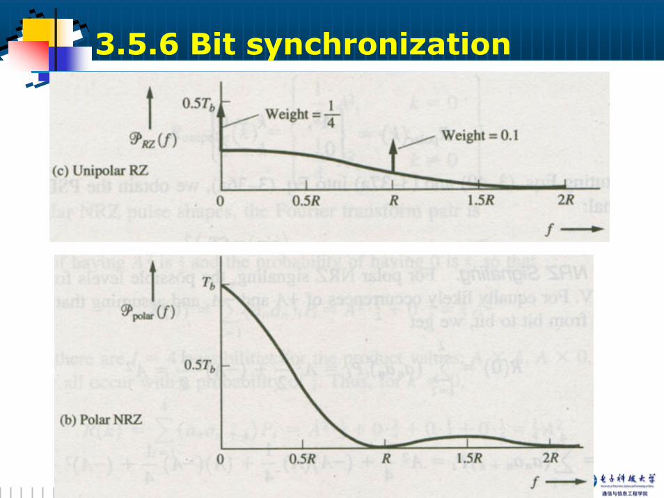
The complexity of the bit synchronizer circuit depends on the sync properties of the line code.
Example:The methods to obtain the bit sync clock signal for a unipolar RZ code:
To use narrowband bandpass filterTo use the phase-locked loop (PLL)
Example: the bit synchronizer for a polar NRZ line code.
3.5.6 Bit synchronization
7878 Your site here
3.5.6 Bit synchronization
7979 Your site here
Note: Unipolar, polar, and bipolar bit synchronizers will work only when there are a sufficient number of alternating 1’s and 0’s in the data.
Long strings of all 1’s or 0’s must be prevented.
To use bit interleaving ;To use a completely different type of line code that does not require alternating data for bit synchronization.
3.5.6 Bit synchronization
8080 Your site here
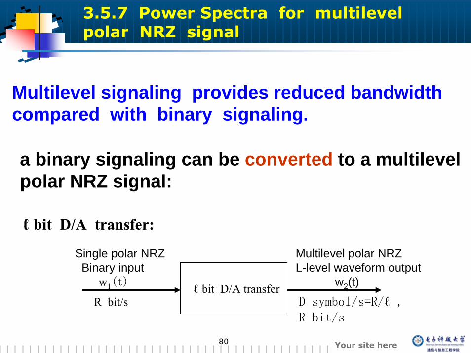
Multilevel signaling provides reduced bandwidth compared with binary signaling.
ℓ bit D/A transfer:
ℓ bit D/A transferR bit/s D symbol/s=R/ℓ ,
R bit/s
Single polar NRZBinary input
w1(t)
Multilevel polar NRZL-level waveform output
w2(t)
3.5.7 Power Spectra for multilevel polar NRZ signal
a binary signaling can be converted to a multilevel polar NRZ signal:
8181 Your site here
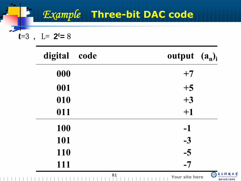
ℓ=3 , L= 2ℓ= 8
digital code output (an)i
000 +7001 +5010 +3011 +1
100 -1101 -3110 -5111 -7
Example Three-bit DAC code
8282 Your site here
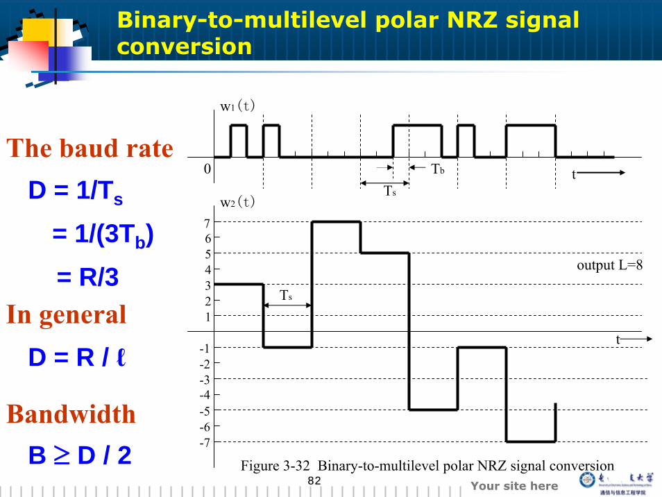
Binary-to-multilevel polar NRZ signal conversion
The baud rateD = 1/Ts
= 1/(3Tb)= R/3
In generalD = R / ℓ
Tb
Ts
t0
w1(t)
w2(t)
Ts
t
76543
-2
21
-1
-3-4-5-6-7
output L=8
Figure 3-32 Binary-to-multilevel polar NRZ signal conversion
Bandwidth B ≥ D / 2
8383 Your site here
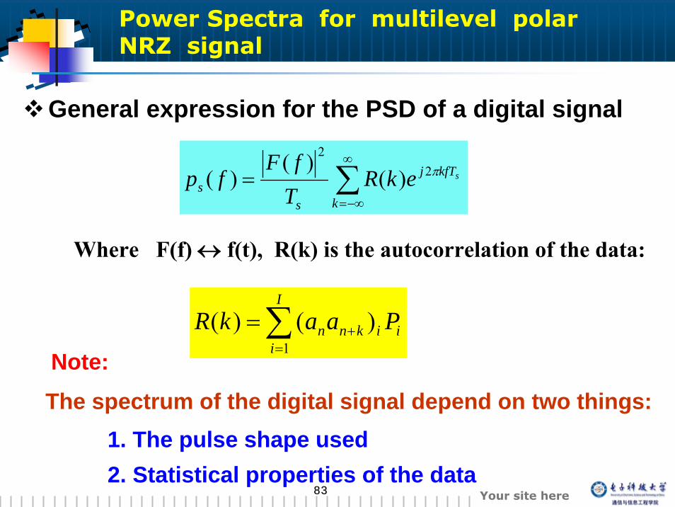
General expression for the PSD of a digital signal
∑∞
−∞=
=k
kfTj
ss
sekRTfF
fp π22
)()(
)(
∑=
+=I
iiiknn PaakR
1)()(
Where F(f) ↔ f(t), R(k) is the autocorrelation of the data:
Note:
The spectrum of the digital signal depend on two things:1. The pulse shape used2. Statistical properties of the data
Power Spectra for multilevel polar NRZ signal

8484 Your site here
For the where case ℓ=3 , Ts=3Tb, the rectangular pulse shape of width 3Tb:
2
33sin63)(
2 ⎟⎟⎠
⎞⎜⎜⎝
⎛=
b
bb fT
fTTfpw π
π
the first null bandwidth for this multilevel polar NRZ signal is:
331 RT
Bb
null ==
----- one-third the bandwidth of the input binary signal
Power Spectra for multilevel polar NRZ signal
8585 Your site here
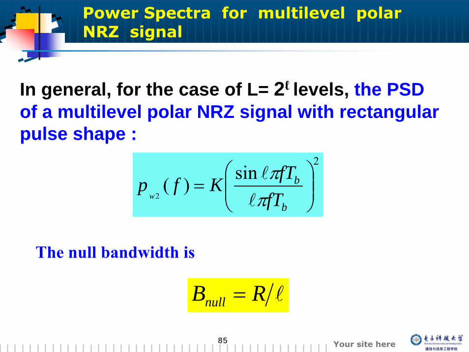
The null bandwidth is
2sin)(
2 ⎟⎟⎠
⎞⎜⎜⎝
⎛=
b
b
fTfTKfp
w ππ
l
l
In general, for the case of L= 2ℓ levels, the PSD of a multilevel polar NRZ signal with rectangular pulse shape :
lRBnull =
Power Spectra for multilevel polar NRZ signal
8686 Your site here
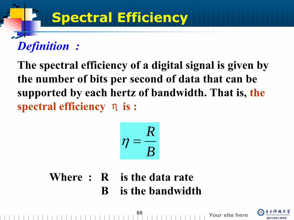
Definition :
Where : R is the data rate B is the bandwidth
Spectral Efficiency
BR
=η
The spectral efficiency of a digital signal is given by the number of bits per second of data that can be supported by each hertz of bandwidth. That is, the spectral efficiency η is :
8787 Your site here
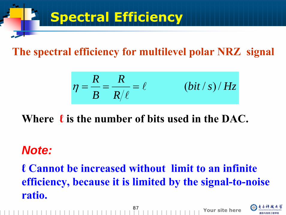
The spectral efficiency for multilevel polar NRZ signal
Where ℓ is the number of bits used in the DAC.
HzsbitRR
BR /)/(l
l===η
Note:ℓ Cannot be increased without limit to an infinite efficiency, because it is limited by the signal-to-noise ratio.
Spectral Efficiency
8888 Your site here
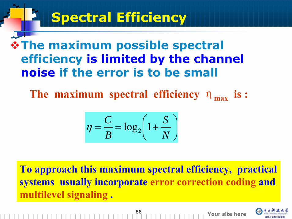
The maximum possible spectral efficiency is limited by the channel noise if the error is to be small
The maximum spectral efficiency ηmax is :
⎟⎠⎞
⎜⎝⎛ +==
NS
BC 1log2η
To approach this maximum spectral efficiency, practical systems usually incorporate error correction coding and multilevel signaling .
Spectral Efficiency
8989 Your site here
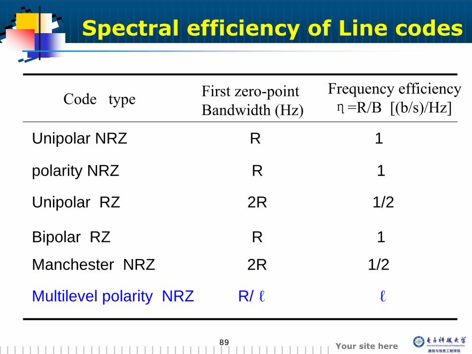
Code type First zero-pointBandwidth (Hz)
Frequency efficiencyη=R/B [(b/s)/Hz]
Unipolar NRZ R 1
polarity NRZ R 1
Unipolar RZ 2R 1/2
Bipolar RZ R 1
Manchester NRZ 2R 1/2
Multilevel polarity NRZ R/ ℓ ℓ
Spectral efficiency of Line codes