chapter 3: crystal structuresamoukasi/cbe30361/lecture_x... · • experiment in 1912, nobel prize...
TRANSCRIPT

ISSUES TO ADDRESS...
• Historical retrospective
• Henry Bragg Equation
• XRD-analysis
• How to read XRD patterns?
• Exclusions
• What questions can be answered by XRD method?
CHAPTER 3: CRYSTAL STRUCTURES X-Ray Diffraction (XRD)
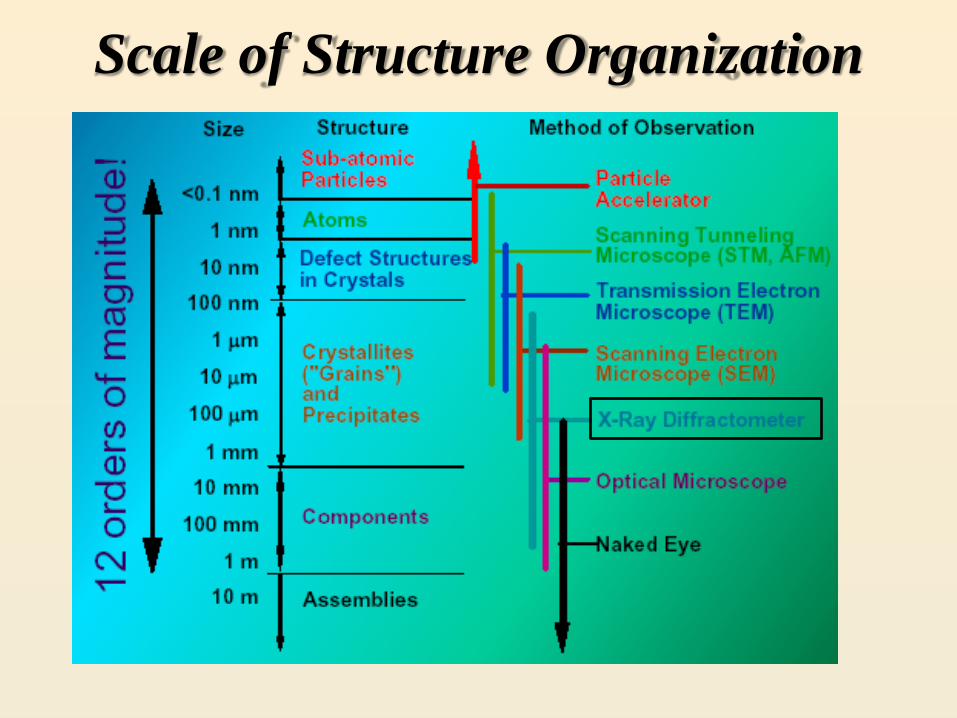
Scale of Structure Organization

Crystal Structure
Practical questions to address:
How to define what crystal structure do we have?
Or in another words: what phases do we have?
Do we have defects or strain in our structure?
Materials science became a real science
due to the development of modern
analysis and imaging techniques.
Modern analysis and imaging techniques
become possible due to developments in
the materials science ……
From art
to science

Nature of light
• Newton: particles (corpuscles)
• Huygens: waves
• Thomas Young double
slit experiment (1801)
• Path difference phase difference
• Light consists of waves !
• Wave-particle duality
See additional file Interference of Light Waves on my website
Schematic diagram of Young’s double slit experiment.
Slits S1 and S2 behave as coherent source of light waves
that produce interference pattern on the viewing screen
S1
S2
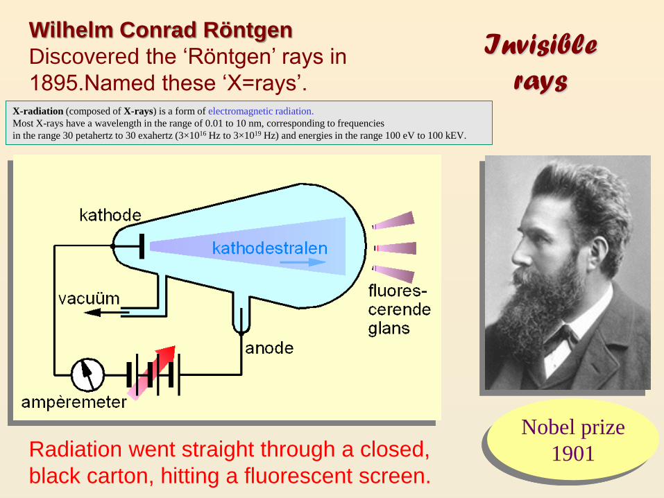
Radiation went straight through a closed,
black carton, hitting a fluorescent screen.
Nobel prize
1901
Invisible
rays
Wilhelm Conrad Röntgen
Discovered the ‘Röntgen’ rays in
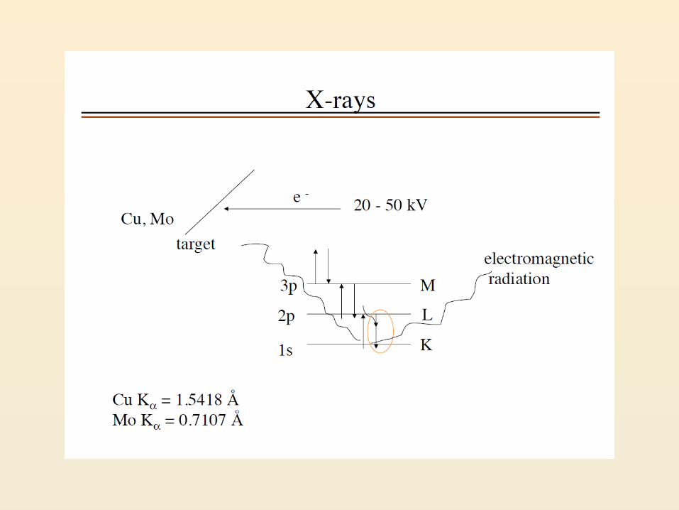
1895.Named these ‘X=rays’. X-radiation (composed of X-rays) is a form of electromagnetic radiation.
Most X-rays have a wavelength in the range of 0.01 to 10 nm, corresponding to frequencies
in the range 30 petahertz to 30 exahertz (3×10¹⁶ Hz to 3×10¹⁹ Hz) and energies in the range 100 eV to 100 kEV.
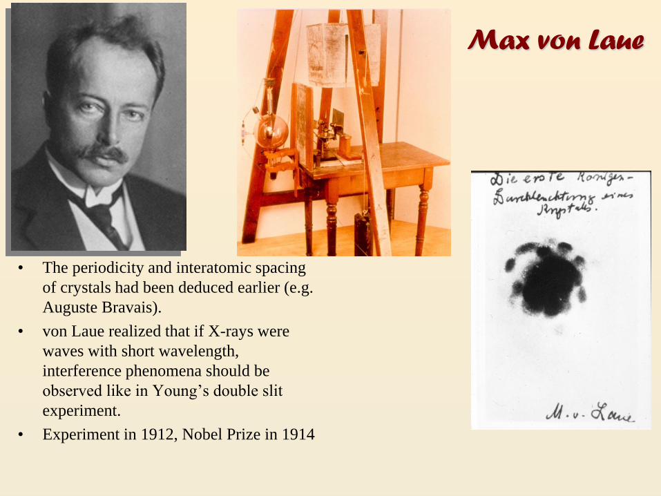
• The periodicity and interatomic spacing
of crystals had been deduced earlier (e.g.
Auguste Bravais).
• von Laue realized that if X-rays were
waves with short wavelength,
interference phenomena should be
observed like in Young’s double slit
experiment.
• Experiment in 1912, Nobel Prize in 1914
Max von Laue

Sir William Henry Bragg: •William Henry and William Lawrence Bragg
(father and son) found a simple interpretation
of von Laue’s experiment.
• They assume that each crystal plane reflects
radiation as a mirror and analyze this situation for
cases of constructive and destructive interference.
The most important thing in science is not so much to obtain
new facts as to discover new ways of thinking about them.
2d nsin Conditions for reflection:
Noble prize 1915!
Bragg’s law
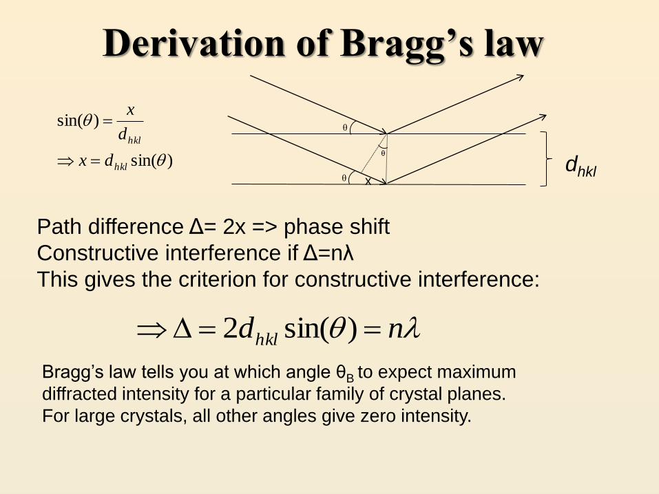
Derivation of Bragg’s law
)sin(
)sin(
hkl
hkl
dx
d
x
Path difference Δ= 2x => phase shift
Constructive interference if Δ=nλ
This gives the criterion for constructive interference:
ndhkl )sin(2
θ
θ
θ
x dhkl
Bragg’s law tells you at which angle θB to expect maximum
diffracted intensity for a particular family of crystal planes.
For large crystals, all other angles give zero intensity.

Conclusions: DIFFRACTION AND THE BRAGG EQUATION
Max von Laue was the first to
suggest that crystals might
diffract X-rays and he also
provided the first explanation
for the diffraction observed.
However, it is the explanation
provided by Bragg that is simpler
and more popular.
incidentbeam
reflectedbeam
x
y
m n
d
o o
o o
o oA B
C D
a
incidentbeam
reflectedbeam
x
y
m n
d
o o
o o
o oA B
C D
d
aUNITCELL
Z
O P
(a)
(b)
Fig. 11
(2,0,0)
(1,0,0)
E F
UNIT
CELL
In the Bragg view crystal
planes act a mirrors.
Constructive interference
is observed when the path
difference between the two
reflected beams in (a) = n.
The path difference in (a) is
2my. Since my/d = sin
2my = 2dsin n where d is
the interplanar spacing.
sin2 )0,0,1(d This is a first order reflection
2sin2 )0,0,1( d This is a second order reflection
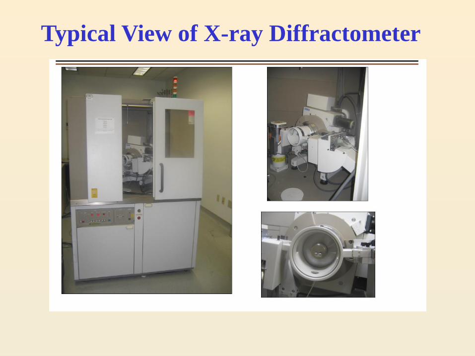
Typical View of X-ray Diffractometer
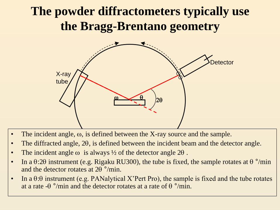
The powder diffractometers typically use
the Bragg-Brentano geometry
w 2
• The incident angle, w, is defined between the X-ray source and the sample.
• The diffracted angle, 2, is defined between the incident beam and the detector angle.
• The incident angle w is always ½ of the detector angle 2 .
• In a :2 instrument (e.g. Rigaku RU300), the tube is fixed, the sample rotates at °/min and the detector rotates at 2 °/min.
• In a : instrument (e.g. PANalytical X’Pert Pro), the sample is fixed and the tube rotates at a rate - °/min and the detector rotates at a rate of °/min.
X-ray
tube
Detector


A single crystal specimen in a Bragg-Brentano diffractometer
would produce only one family of peaks in the diffraction
pattern.
2
At 20.6 °2, Bragg’s law
fulfilled for the (100) planes,
producing a diffraction peak.
The (110) planes would diffract at 29.3
°2; however, they are not properly
aligned to produce a diffraction peak
(the perpendicular to those planes does
not bisect the incident and diffracted
beams). Only background is observed.
The (200) planes are parallel to the (100)
planes. Therefore, they also diffract for this
crystal. Since d200 is ½ d100, they appear at
42 °2.
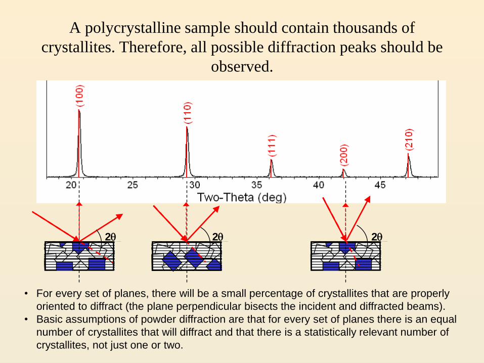
A polycrystalline sample should contain thousands of
crystallites. Therefore, all possible diffraction peaks should be
observed.
2 2 2
• For every set of planes, there will be a small percentage of crystallites that are properly
oriented to diffract (the plane perpendicular bisects the incident and diffracted beams).
• Basic assumptions of powder diffraction are that for every set of planes there is an equal
number of crystallites that will diffract and that there is a statistically relevant number of
crystallites, not just one or two.

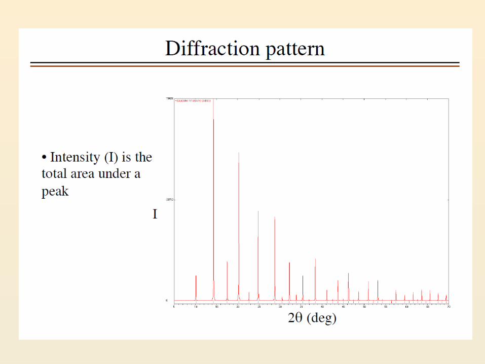
Example: Diffraction Patterns • Each peak represents the solution to Bragg’s law for known radiation
wavelength ( = 0.154nm)
• The unique relationship between such patterns and crystal structures
provide a powerful tool for identification of the phase composition of
powders and polycrystalline materials.


Structure Factor The general expression for :
Now we apply this to various crystals. First, consider examples of crystals with a basis group of just one
atom per lattice point, with atomic scattering factor f. The results are valid for any crystal system.
Primitive Cells This is really simple! N = 1, so
Define the position of the cell so that our atom is at uvw = 000; then (hu+kv+lw) = 0,
and we get just
so
F fne2i(hun kvn lwn )
n1
N
F fne2i(hun kvn lwn )
n1
N
fe2i(hukvlw)
F fe2i(0) f
F f

Basis and Bravais Structure Factor Terms
F e2 igrn fme2 igrm
m1
Nb
FBRFBAn1
Np
The following simple table giving the integer values of FBR for the different types of centering
translations. Keep in mind that these are valid for any crystal system.
hkl unmixedhkl mixed
(h + k) even(h + k) odd
(h + l) even(h + l) odd
(k + l) even(k + l) odd
4
2
2
2
2
1All
(h + k + l) even(h + k + l) odd
None
F (face-centered)
C (base-centered on C face)
B (base-centered on B face)
A (base-centered on A face)
I (body-centered)
P (primitive)
Bravais Term FBR for
possible reflections
Possible Reflections(FBR ° 0)
Missing Reflections (FBR = 0)
Centering type


Summary