chapter 3 simplicity & extensibility of architectureyuba.stanford.edu/~sd2/ch_3.pdf · 82...
TRANSCRIPT
82
Chapter 3
Simplicity & Extensibility of
Architecture
We proposed a unified control architecture for packet and circuit networks based on two
abstractions: the common-flow and the common-map abstraction. We discussed an
implementation of the architectural approach using OpenFlow and NOX, and presented
several prototypes that helped us understand and refine our implementation. In this
chapter we wish to validate the simplicity and extensibility claims of our architectural
approach. Unified control over packets and circuits enables us to develop new
networking capabilities that benefit from the strengths of the two switching technologies.
Thus, the first step of our validation methodology involves developing a new network
capability; in this work, we choose to develop the ability for the network to treat different
kinds of traffic differently, using both packets and circuits at the same time. Specifically
the network treats voice, video and web traffic differently in terms of the bandwidth,
latency and jitter experienced by the traffic, as well as the priority with which traffic is
re-routed around a failure. We implement this capability on an emulated WAN using the
full pac.c prototype discussed in Sec. 2.3.3. The second step of the validation process
involves comparing our implementation, to an implementation which would use the
current state-of-the-art industry-standard control-plane solution.
83
In support of our simplicity claim, we find that our implementation requires two
orders of magnitude less code than the industry-standard solution. Lines-of-code
differing by orders of magnitude are good indicators of the complexity in developing and
maintaining one code-base compared to another. And so we conclude that our control-
architecture enables simpler implementations of control-applications.
In support of our extensibility claim, we first discuss the two reasons that make our
solution extensible: a) full visibility across packets and circuits; and b) the ability to write
control applications in a centralized way, where the state-distribution mechanisms have
been abstracted away. We find that the current industry standard supports neither of the
two; which is why it is not surprising that even with two orders of magnitude more code,
the industry solution cannot replicate the network capability we demonstrate. Next, as
further proof of extensibility, we discuss three other examples of applications enabled at
the intersection of packet and circuit switching: dynamic packet-links; variable-
bandwidth packet links; and unified-routing.
Finally we discuss three deployment challenges faced by any unified control solution
for packet and circuit networks. The challenges include: a) the reluctance of network
operators of packet and circuit networks to share information with each other; b) the
conservative nature of transport network operators towards automated control planes; and
c) the conservative nature of IP network operators towards increasing load on distributed
routing protocols. As final validation of the simplicity and extensibility of our work, we
propose solutions based on our control architecture to all the deployment challenges
mentioned above.
3.1 Demonstration of New Network Capability
The goal of the network function (or capability) we have chosen to implement is ‘to treat
different kinds of traffic differently’. We first describe what kinds of traffic we deal with,
and briefly why we wish to give them different treatment. We identify how we achieve

84
CHAPTER 3. SIMPLICITY & EXTENSIBILITY OF ARCHITECTURE
our goals by leveraging the benefits of both packets and circuits, as well as our common-
global view of both networks and common control over both switching technologies (Fig.
3.1). We then briefly describe the software architecture of our system and network
application, and give details of our demonstration [52, 53].
Figure 3.1: Example Network Function
3.1.1 Example Network Function
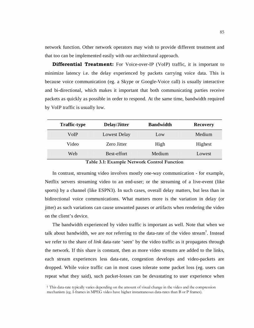
The network function is designed to provide differential treatment to three types of traffic
– voice, video and web. Table 3.1 shows the differential treatment we designate for these
types of traffic with respect to delay, jitter and bandwidth experienced by the traffic, and
priorities given to re-routing said traffic around failures.
It is important to note that this is just an example of a function that we (as a network
operator) wish for our network to perform. It is by no means the only application that can
be performed, nor is it the only kind of treatment that can be delivered to these types of
traffic. We have simply chosen this treatment to demonstrate a reasonably involved
85
network function. Other network operators may wish to provide different treatment and
that too can be implemented easily with our architectural approach.
Differential Treatment: For Voice-over-IP (VoIP) traffic, it is important to
minimize latency i.e. the delay experienced by packets carrying voice data. This is
because voice communication (eg. a Skype or Google-Voice call) is usually interactive
and bi-directional, which makes it important that both communicating parties receive
packets as quickly as possible in order to respond. At the same time, bandwidth required
by VoIP traffic is usually low.
Table 3.1: Example Network Control Function
In contrast, streaming video involves mostly one-way communication - for example,
Netflix servers streaming video to an end-user; or the streaming of a live-event (like
sports) by a channel (like ESPN3). In such cases, overall delay matters, but less than in
bidirectional voice communications. What matters more is the variation in delay (or
jitter) as such variations can cause unwanted pauses or artifacts when rendering the video
on the client’s device.
The bandwidth experienced by video traffic is important as well. Note that when we
talk about bandwidth, we are not referring to the data-rate of the video stream†. Instead
we refer to the share of link data-rate ‘seen’ by the video traffic as it propagates through
the network. If this share is constant, then as more video streams are added to the links,
each stream experiences less data-rate, congestion develops and video-packets are
dropped. While voice traffic can in most cases tolerate some packet loss (eg. users can
repeat what they said), such packet-losses can be devastating to user experience when
Traffic-type Delay/Jitter Bandwidth Recovery
VoIP Lowest Delay Low Medium
Video Zero Jitter High Highest
Web Best-effort Medium Lowest
† This data-rate typically varies depending on the amount of visual change in the video and the compression mechanism (eg. I-frames in MPEG video have higher instantaneous data-rates than B or P frames).
86
CHAPTER 3. SIMPLICITY & EXTENSIBILITY OF ARCHITECTURE
watching video (pauses, artifacts such as black-spots or discoloration). And so, not only
do we give a larger share of bandwidth to video traffic, we ensure that as more video is
added to the network, the bandwidth experienced by the traffic remains high in order to
avoid or minimize video-packet losses.
Finally we deem web-traffic† to be best effort, in that we do not make any special
requirements for delay or jitter. We choose to allocate medium levels of data-rate for this
traffic class (more or similar to voice but less than video). Importantly, we do not ensure
that data-rate ‘seen’ by web or voice traffic remains at the same levels at all times. And
when failure of some kind happens in the network (link or node), we prioritize the
recovery of all video traffic, over voice or web traffic.
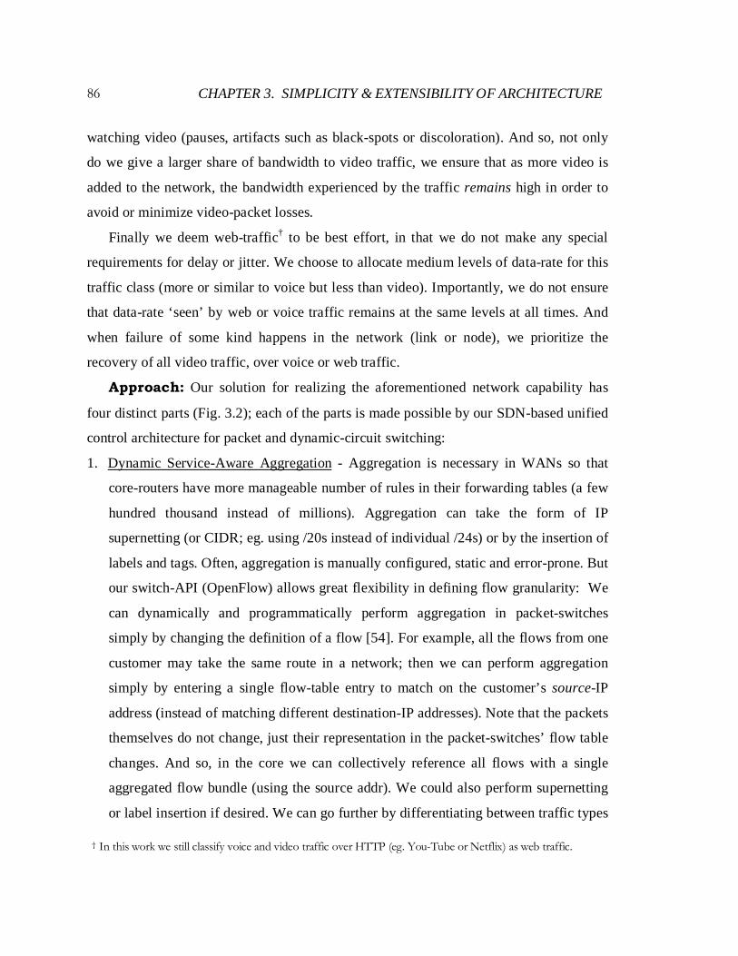
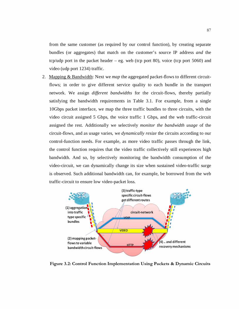
Approach: Our solution for realizing the aforementioned network capability has
four distinct parts (Fig. 3.2); each of the parts is made possible by our SDN-based unified
control architecture for packet and dynamic-circuit switching:
1. Dynamic Service-Aware Aggregation - Aggregation is necessary in WANs so that
core-routers have more manageable number of rules in their forwarding tables (a few
hundred thousand instead of millions). Aggregation can take the form of IP
supernetting (or CIDR; eg. using /20s instead of individual /24s) or by the insertion of
labels and tags. Often, aggregation is manually configured, static and error-prone. But
our switch-API (OpenFlow) allows great flexibility in defining flow granularity: We
can dynamically and programmatically perform aggregation in packet-switches
simply by changing the definition of a flow [54]. For example, all the flows from one
customer may take the same route in a network; then we can perform aggregation
simply by entering a single flow-table entry to match on the customer’s source-IP
address (instead of matching different destination-IP addresses). Note that the packets
themselves do not change, just their representation in the packet-switches’ flow table
changes. And so, in the core we can collectively reference all flows with a single
aggregated flow bundle (using the source addr). We could also perform supernetting
or label insertion if desired. We can go further by differentiating between traffic types
† In this work we still classify voice and video traffic over HTTP (eg. You-Tube or Netflix) as web traffic.
87
from the same customer (as required by our control function), by creating separate
bundles (or aggregates) that match on the customer’s source IP address and the
tcp/udp port in the packet header – eg. web (tcp port 80), voice (tcp port 5060) and
video (udp port 1234) traffic.
2. Mapping & Bandwidth: Next we map the aggregated packet-flows to different circuit-
flows; in order to give different service quality to each bundle in the transport
network. We assign different bandwidths for the circuit-flows, thereby partially
satisfying the bandwidth requirements in Table 3.1. For example, from a single
10Gbps packet interface, we map the three traffic bundles to three circuits, with the
video circuit assigned 5 Gbps, the voice traffic 1 Gbps, and the web traffic-circuit
assigned the rest. Additionally we selectively monitor the bandwidth usage of the
circuit-flows, and as usage varies, we dynamically resize the circuits according to our
control-function needs. For example, as more video traffic passes through the link,
the control function requires that the video traffic collectively still experiences high
bandwidth. And so, by selectively monitoring the bandwidth consumption of the
video-circuit, we can dynamically change its size when sustained video-traffic surge
is observed. Such additional bandwidth can, for example, be borrowed from the web
traffic-circuit to ensure low video-packet loss.
Figure 3.2: Control Function Implementation Using Packets & Dynamic Circuits

88
CHAPTER 3. SIMPLICITY & EXTENSIBILITY OF ARCHITECTURE
3. Routing for Delay & Jitter: We can tailor a circuit to have routing characteristics
beneficial for an application or service. For instance, the VoIP traffic-circuit can be
routed over the shortest path in the physical fiber topology. In contrast, the video-
bundle can be routed over a path with zero-jitter by bypassing intermediate packet-
switches (that would introduce jitter) between source and destination routers.
4. Prioritized Recovery: Finally, once we have global knowledge and centralized
decision making, we can recover from network failures so as to meet application
needs. For example, video traffic could be circuit-protected with pre-provisioned
bandwidth (ensuring fastest recovery), while all voice could be dynamically re-routed
by the controller before any web-traffic is re-routed.
Software Architecture & Implementation: Next we present the software
architecture of our implementation on top of the common-map abstraction. We highlight
a few features of the software architecture with respect to discussions from previous
chapters:
• First, note that Fig. 3.3 is an extension of Fig. 2.19, where we have added network-
applications on top of the changes we previously made to NOX. To recap, such
changes were required to create the common-map abstraction; and they included
changes to the OpenFlow protocol; modules for Circuit-Link-Verification and circuit
Topology; a Circuit-Switch-API for manipulating switches in the common-map
directly; as well as a network-API for network-wide control functions.
• Second, we had previously stated that the common-map abstraction does not preclude
any layering choice for packets and circuits. In this particular example we choose to
treat the circuit and packet topologies in different layers (corresponding to the left-
side of Fig. 2.12). As an example of a different layering choice, later in this chapter
(Sec. 3.4) we discuss an example application that treats the topologies as one (in a de-
layered way).

89
• Third, while flow databases (for both packet and circuit flows- see Fig. 1.11) can be a
part of the common-map as they reflect network state, often the decision to retain
such state in the controller is left up to the application-writer. Applications may
decide not to keep any flow-state in the controller as such state can be voluminous
and ephemeral (and therefore quickly get out of hand). In such cases, when there is
change in network-state which requires changes to flow-state, the latter can be re-
computed. But more slowly varying flow-state such as aggregated packet-flows and
more manageable flow-state such as circuit flows (fewer cflows than pflows) may
well be retained in the controller. Accordingly we choose to retain state of such flows
in the AggregationDB and cFlowDB.
Figure 3.3: Software Architecture
Since we chose to retain packet and circuit layering in this example, we have separate
routing modules for packets and circuits. The Packet-Routing module is responsible for
finding shortest paths over the packet topology for aggregated bundles of packet-flows.
90
CHAPTER 3. SIMPLICITY & EXTENSIBILITY OF ARCHITECTURE
Such aggregated bundles are created by the Service-Aware Aggregation module, which
classifies incoming packets into traffic-type specific bundles and informs the Mapping &
Bandwidth module of desired circuit-flow characteristics. The latter application maps
aggregated packet-flows to circuit-flows, and determines their bandwidth allocations. It is
also responsible for constraining the Circuit-Routing module to determine routes for the
circuits according to traffic-specific requirements (delay, jitter, bandwidth etc.).
Additionally it monitors certain circuit flows for their bandwidth usage and resizes the
circuits according to application needs. Finally the Prioritized Recovery module re-routes
circuit-flows upon link-failure according to the network-function guidelines.
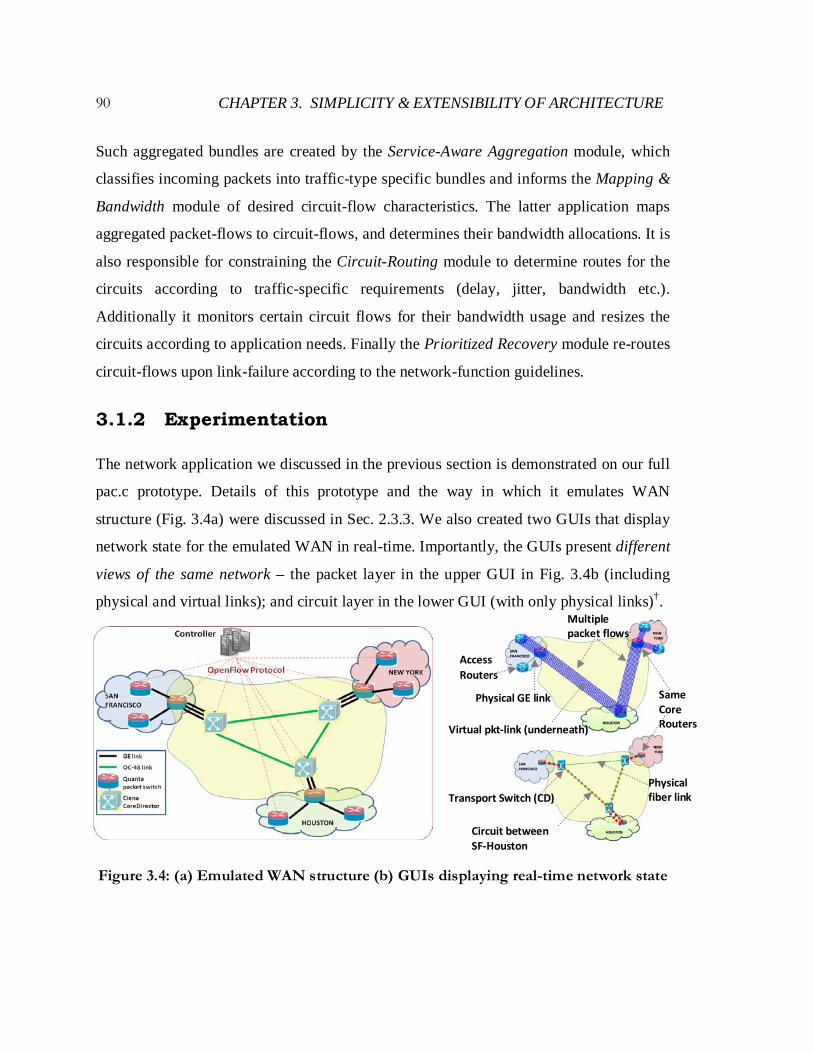
3.1.2 Experimentation
The network application we discussed in the previous section is demonstrated on our full
pac.c prototype. Details of this prototype and the way in which it emulates WAN
structure (Fig. 3.4a) were discussed in Sec. 2.3.3. We also created two GUIs that display
network state for the emulated WAN in real-time. Importantly, the GUIs present different
views of the same network – the packet layer in the upper GUI in Fig. 3.4b (including
physical and virtual links); and circuit layer in the lower GUI (with only physical links)†.
Figure 3.4: (a) Emulated WAN structure (b) GUIs displaying real-time network state
Access Routers
Same Core Routers
Physical GE link
Virtual pkt-link (underneath)
Multiple packet flows
Transport Switch (CD)
Circuit between SF-Houston
Physical fiber link

91
GUI-views: The upper GUI in Fig. 3.4b shows packet-switches in three city-PoPs.
Physical GE links connect Access-Routers to Core-Routers within each PoP. Between
cities, the links shown in the upper GUI correspond to virtual packet-links. These virtual
links are supported by circuits-flows in the underlying circuit-layer (shown in the lower
GUI). The packet-layer view in the upper GUI also shows packet flows currently routed
in the network – for example, multiple packet-flows are shown in Fig. 4.3b routed from
an SFO Access Router to a NY Access Router via the Core Routers in SFO, Houston and
NY(obscuring the view of the links underneath). Note that the upper GUI does not show
any circuit-switching equipment.
The lower GUI in Fig. 3.4b displays the transport-switches – i.e. the CoreDirectors
(CDs); the physical fiber topology; and only those packet switches that are physically
connected to the CDs. As a result, note that the Core-Routers in all three cities appear in
both GUIs – in the upper one they are at the ends of the virtual-packet links over the wide
area; and in the lower one, they are physically connected to the CDs. The lower GUI also
displays circuit-flows – for example two circuits are shown, one each between SF-
Houston and Houston-NY, which support the virtual-packet-links and packet-flows
shown in the upper GUI. To further clarify, note that a virtual-packet link between core-
routers (in the upper GUI) can be supported by single or multi-hop circuits in the
transport network (lower GUI view), as shown in Fig. 3.5.
Figure 3.5: GUI views

92
CHAPTER 3. SIMPLICITY & EXTENSIBILITY OF ARCHITECTURE
Application-Aware Aggregation: Initially, traffic consists of 10 flows from
customer 1. The flows are routed from SF to NY via the Houston Core-Router. Without
aggregation, each flow is treated individually by the network, based on the shortest path
between source and destination. In other words, there are 10 flow-table entries, for each
flow’s destination IP address, in each packet-switch along the path. The Service-Aware
Aggregation module dynamically performs aggregation by creating three bundles
(aggregated packet-flows), one for each traffic type from the same customer, by matching
on the customer’s source IP address and the tcp/udp ports in the packet header (packet
GUI in Fig. 3.6a).
Note from the circuit GUI in Fig. 3.6a, these 3 application-specific bundles still take
the same route in the core, i.e they go from the SF Core Router to the SF CD, then over
the circuit to the Houston CD; then to the Houston Core Router; where it gets switched
back to the Houston CD to go over the circuit to the NY CD and finally to the NY Core
Router. In other words, all 3 bundles are still treated the same way in the network.
Figure 3.6: (a) Service-aware Aggregation (b) VoIP treatment
Video bundle
VoIP bundle
HTTP bundle
SF- HOU circuit
NY-HOU circuit
(3) VoIP bundle re-routed over newly
created (virtual) packet-link
(1) VoIP circuit created over shortest
propagation path (a) (b)
(2) brings up a new virtual packet-link
between SFO-NY
93
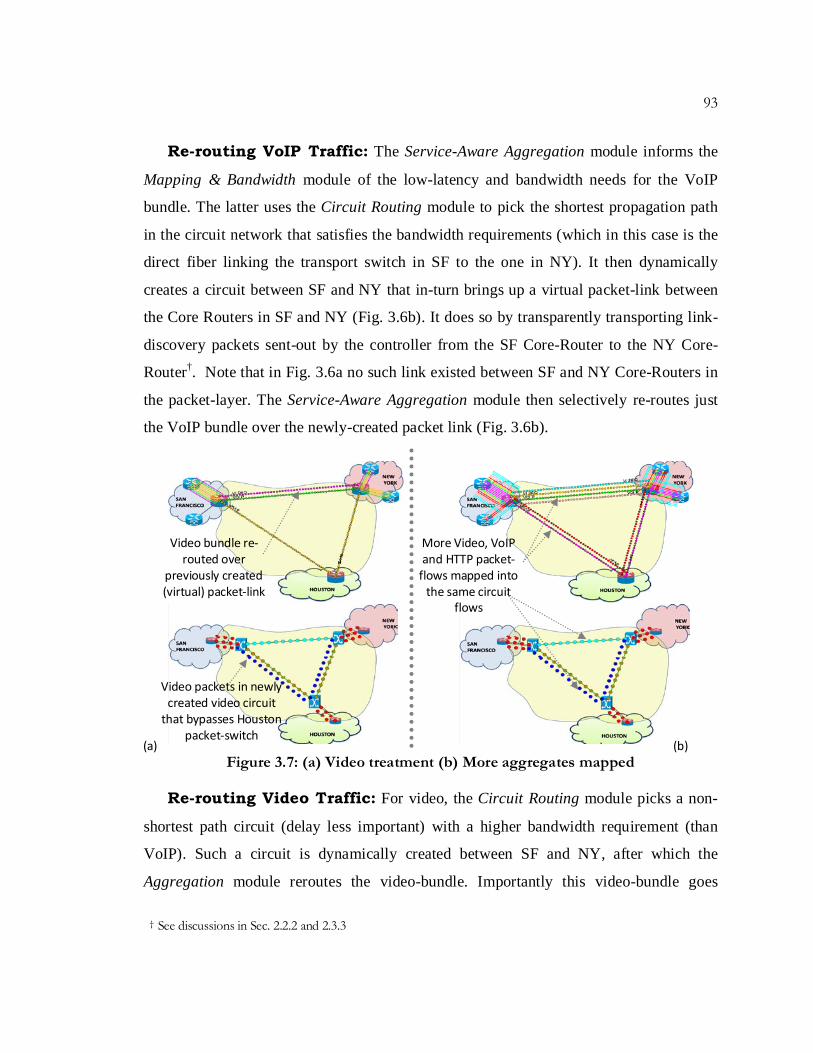
Re-routing VoIP Traffic: The Service-Aware Aggregation module informs the
Mapping & Bandwidth module of the low-latency and bandwidth needs for the VoIP
bundle. The latter uses the Circuit Routing module to pick the shortest propagation path
in the circuit network that satisfies the bandwidth requirements (which in this case is the
direct fiber linking the transport switch in SF to the one in NY). It then dynamically
creates a circuit between SF and NY that in-turn brings up a virtual packet-link between
the Core Routers in SF and NY (Fig. 3.6b). It does so by transparently transporting link-
discovery packets sent-out by the controller from the SF Core-Router to the NY Core-
Router†. Note that in Fig. 3.6a no such link existed between SF and NY Core-Routers in
the packet-layer. The Service-Aware Aggregation module then selectively re-routes just
the VoIP bundle over the newly-created packet link (Fig. 3.6b).
Figure 3.7: (a) Video treatment (b) More aggregates mapped
Re-routing Video Traffic: For video, the Circuit Routing module picks a non-
shortest path circuit (delay less important) with a higher bandwidth requirement (than
VoIP). Such a circuit is dynamically created between SF and NY, after which the
Aggregation module reroutes the video-bundle. Importantly this video-bundle goes
† See discussions in Sec. 2.2.2 and 2.3.3
Video bundle re-routed over
previously created (virtual) packet-link
Video packets in newly created video circuit
that bypasses Houston packet-switch
More Video, VoIP and HTTP packet-
flows mapped into the same circuit
flows
(a) (b)

94
CHAPTER 3. SIMPLICITY & EXTENSIBILITY OF ARCHITECTURE
through the Houston PoP but stays in the circuit layer, bypassing the Houston Core
Router, and therefore avoids potential jitter in that router.
Note that in the packet-GUI in Fig. 3.7a, the video-bundle appears to go over the
same virtual-packet-link between SF and NY that was created for the VoIP bundle. In
reality the VoIP and Video bundles use the same physical-port on the SF Core Router but
end up taking different physical paths in the circuit network (as discussed in Sec. 2.3.3);
ones that are suited for the traffic-type.
Also note that the web-traffic still uses the original SF-Houston-NY path in the
packet-layer and is therefore treated as best-effort; i.e. no special circuits are created for
web traffic. As more traffic arrives for all three kinds of traffic, from the same or
different customers, they are similarly aggregated and mapped into the circuit-flows
created for them (see upper GUI in Fig. 3.7b).
Figure 3.8: (a) Bandwidth increased for Video (b) Prioritized Recovery
Monitoring & Recovery: Also as traffic increases, the Mapping & Bandwidth
module monitors the bandwidth usage of the circuits to accommodate for traffic growth.
In Fig. 3.8a, the video-circuit is dynamically re-sized when sustained traffic surge is
Video-circuit bandwidth increased
Fiber-cut
Video-circuit rerouted with
higher priority than web -circuit
(b) (a)

95
observed, as per the requirement of having video-traffic experience high-bandwidth.
Finally, the Prioritized Recovery module dynamically re-routes circuits upon failure. In
Fig. 3.8b, when the fiber-link between SF and Houston breaks, all video-traffic based
circuits are re-routed before re-routing the circuits meant for best-effort web traffic.
Conclusions: In this section, we achieved the first step of the validation
methodology outlined in the introduction. We discussed a new network capability and
showed how it could be implemented using packets and dynamic-circuits commonly
controlled within our unified control architecture. We showed how voice, video and web
traffic can be classified, aggregated and mapped into specially routed, dynamically
created, monitored circuits to achieve differential treatment. In the next two sections, we
move to the next step of our validation methodology, by comparing our work with ways
in which such capabilities could be replicated using current industry solutions.
3.2 Comparison to Existing Solutions: Simplicity
In the previous chapters we claimed the benefits of simplicity and extensibility of our
architecture compared to existing industry solutions. In this section we validate our
simplicity claim. But first we explain what we are comparing our solution to, by detailing
the current industry solution. We investigate the requirements for providing a service or
network capability such as one described in Sec. 3.1, across packets and circuits with
such industry-based control architecture.
To compare between our implementation and one based on industry solution, we
contrast the Lines of Code required to implement the function. Why do we use Lines of
Code? Because orders of magnitude difference between the lines-of-code for different
software projects can estimate the complexity of the project, in terms of the amount of
effort required to develop the code-base as well the effort required to maintain or change
the code-base after release [59]. We count the physical lines-of-code (without blank and
comment lines) using CLOC [60]. Tables from the analysis are shown in Appendix D.

96
CHAPTER 3. SIMPLICITY & EXTENSIBILITY OF ARCHITECTURE
3.2.1 Implementation with Industry Solution
Today’s packet and circuit networks are not converged networks. Core packet networks
(IP/MPLS) are planned, designed and operated separately from core circuit networks
(Transport networks), even if both networks are owned by the same service provider.
IP Networks: Today’s IP core-networks are no longer plain-vanilla IP networks –
MPLS is widely used. In fact there isn’t a single Tier-1 ISP today that does not run an
IP/MPLS network [56]. We make the observation that MPLS† introduces the concept of
‘flows’ in IP networks [57]. In principle, packets can be classified into Forwarding
Equivalence Classes (FECs); all packets in the same FEC are forwarded the same way via
Label Switched Paths (LSP); and accounting/resource management can be performed on
an LSP level; making FEC+LSPs similar to our ‘flow’ definition (Sec. 1.4.1).
Transport Networks: Today’s transport networks are divided into vendor-
islands (Fig. 3.9). The switches within a vendor-island support proprietary control and
management interfaces that only work with the vendor’s EMS/NMS. In other words, they
do not interoperate on the control plane with switches in other vendor islands. Note that
the multiple vendor islands shown in Fig. 3.9 still represent a single carrier’s transport
network, and the operation of such a network is highly manual (human-driven NMS).
Figure 3.9: Industry Solution for IP and Transport Network Control
† We will have much more to say about MPLS, the flow-abstraction and the map-abstraction in Ch. 5

97
The industry has developed an interoperable automated, control plane solution
(GMPLS) based on the MPLS control plane protocols. Such protocols were adopted and
extended for circuit switching features by the standards bodies (IETF and ITU). GMPLS
protocols were used to stitch together the vendor-islands as a layer above the proprietary
interfaces, which remained the same as before. Collectively the proprietary interfaces are
known as I-NNI and the stitching interface is the E-NNI. Finally, an additional interface
known as the UNI was defined, for client-networks (such as the IP network) to interface
with and request services from the transport network†.
So collectively the MPLS/GMPLS/UNI/NNI solution would look like Fig. 3.9. As
noted in Sec. 1.5, this industry solution (GMPLS and UNI) has never been commercially
adopted [26, 27]. But it is the only solution proposed by the industry for packet-circuit
network control, and so we use it to investigate and compare to our solution.
Software Stack: The IP/MPLS network is a fully-distributed network where
each router makes decisions on packet forwarding based on a variety of network control-
functions (Fig. 3.10). There are two consequences of such design:
Figure 3.10: Software Stack in Fully-Distributed Control Planes
1. Complexity: Since each router in the network largely makes its own decision,
network-functions/ applications/services are then in most cases, necessarily
implemented in fully distributed-ways, in each and every router in the network. Such
distributed network functions need to implement their own distribution mechanisms,
† For more details on the origins and choices made for GMPLS, see the Related Works Section in Ch. 6.
98
CHAPTER 3. SIMPLICITY & EXTENSIBILITY OF ARCHITECTURE
and depend on them for proper working, leading to exposure to distributed state and
subtle interactions with the mechanisms. This in turn makes it harder to implement
the function (more code to touch), get it right (testing and verification) and maintain it
over time (as function requirements change and/or new functions are introduced). As
an example, from Fig. 3.10, the network functions of distributing IPv4 address,
MPLS labels and link-state are handled by a variety of protocols each with their own
characteristics and nuances. And these are just for unicast IPv4. There are many more
protocols for handling state-distribution for other purposes like IPv6, multicast, etc.
2. Extensibility: In most cases, changes to a network function requires changes to the
distribution mechanism† or the creation of an entirely new distribution mechanism^.
This hurts extensibility of such control-architectures, which we will discuss in the
next section. Here we merely wish to point out again why distributed features are tied
to the distribution mechanisms that support them.
Lines-of-Code: Our control function (in Sec. 3.1) requires the network to a)
differentiate between different types of traffic (voice, video, web) to create traffic-type
specific aggregates and b) forward the aggregates (bundles) differently i.e. not
necessarily along the shortest path in the network. Given the industry standard solution
and structure shown in Fig. 3.9, we need the following protocols and feature
implementations:
• IP-network: An IP/MPLS network would require Policy-Based-Routing [61] for
differentiating between traffic types and forwarding them to different traffic-type
specific tunnels, created using Diffserv-aware MPLS Traffic Engineering (DS-TE)
mechanisms [62]. The DS-TE tunnels can then be routed along paths in the network
that are not necessarily the shortest ones. PBR and DS-TE are typically implemented
by router vendors. We were unable to find an open-source implementation of either.
While PBR is a local-hack in a router at the source-end of an MPLS-TE tunnel, DS-
TE is a distributed application dependant on the distribution mechanisms of OSPF-TE
† The original RSVP protocol (hosts signaling for services - not used anymore), has undergone no less than three such ‘extensions’ – first it was given TE extensions for MPLS, then extensions for transport switches in GMPLS, and then it was extended again for supporting the UNI/E-NNI interfaces.
^ When the MPLS control plane was extended for GMPLS, a new protocol, LMP (RFC 4204) was created in addition to extensions for OSPF and RSVP.

99
and RSVP-TE. Thus we present lower-end estimates for the number of lines of code
that need to be touched for implementing the packet-part of our control-function. We
have counted the lines-of-code (in Appendix D) for two open-source projects that
have implemented OSPF-TE and RSVP-TE. The Quagga project [63] implements the
former in 34,244 lines-of-code, where we have only accounted for the ‘ospfd’
implementation and not any of the other routing protocols that are part of Quagga.
Also since the Quagga suite does not include RSVP-TE, we use the IST-Tequila
project implementation for RSVP-TE [64, 65] (49,983 lines of code).
• UNI Interface: To implement our control function using packets and circuits (Fig.
3.9), one or more routers would have to request services from the transport network
using the UNI interface. The UNI is typically instantiated using a signaling protocol
like RSVP-TE with suitable extensions [22]. We count 9,866 lines-of-code from an
implementation of the OIF UNI protocol from the IST-MUPBED project [66, 67].
• Transport-Network: Finally the GMPLS protocols for the transport network control
plane include further extensions of the MPLS control plane protocols – OSPF-TE and
RSVP-TE. Such extensions have been standardized [20]. We use the DRAGON
project [68, 69] for representative open-source implementations of the GMPLS
protocols – 38,036 lines-of-code for OSPF-TE and 43,676 for RSVP-TE. Note that
we are ignoring the code required for the proprietary interfaces in the transport
network vendor islands (the I-NNI protocols).
If we put together all the lines of code across packet and circuit control-planes, we get
a total of 175,805 lines of code for just the state-distribution mechanisms. In addition,
more lines-of-code would be required to implement the distributed-control logic that
performs the task required by the control function. These logic components would
include PBR, DS-TE, a CSPF algorithm for routing of primary/backup circuit-paths, and
glue-code for translating GMPLS messages to the proprietary interfaces. Based on our
experience with implementing distributed protocols any one of the mentioned logic
components would at a minimum require 5-10k lines-of-code, pushing the total lines-of-

100
CHAPTER 3. SIMPLICITY & EXTENSIBILITY OF ARCHITECTURE
code to well over 200,000. Approximate totals for the lines-of-code are depicted in Fig.
3.11 below.
Figure 3.11: Lines-of-Code in Industry Standard Solution
It is worth mentioning that the 175,000 + ‘x’ lines of code only relate to the network
applications, which include the function-logic as well as the distribution mechanisms.
These applications are implemented on top of some base code – for example, the Quagga
software suite is based on the zebra-daemon and related libraries. This gives us about
52,000 lines of code for the Quagga-base code, built on top of the Linux kernel. Finally,
Fig. 3.12 also shows a closed-source implementation of router software from vendors
such as Cisco (IOS) and Juniper (JUNOS). Such implementations of functions and
services together with distributed protocols and the base operating system for the router
have been known to total approximately 20 million lines-of code (in each router) [70].
Figure 3.12: Source Lines-of-Codes in Distributed Approaches

101
3.2.2 Implementation with Unified Control Architecture
Simplicity comes from not having to implement each control functions as a distributed
system, and not having to worry about interactions with state-distribution mechanisms.
There are two kinds of state-distribution mechanisms in SDNs (Fig. 3.13a):
1. One is between the controller and the switches. In SDNs, the OpenFlow protocol
could be used for this purpose where the controller communicates directly with the
switches one-on-one. Since decision making is no longer the switch’s responsibility,
the need for distributed routing and signaling protocols is removed within a
controllers’ domain. And so such protocols are eliminated.
2. The second distribution mechanism is between the multiple physical servers that
make up a controller. In our work we use NOX as the network OS. NOX is meant to
run on a single server. Commercial network OSes running on multiple servers have
additional functionality for distributing state between these servers thereby increasing
the lines of code for the Net-OS. Importantly, these additions only need to be done
once and are then abstracted away from multiple (centralized) applications that can be
written on top of the common-map abstraction. With proper implementation, these
state-distribution mechanisms would not count as part of feature development cost as
they do not need to be changed or touched in order to implement a new feature.
Figure 3.13: (a) Software Stack and (b) Source Lines-of-Code in SDN
(b) (a)

102
CHAPTER 3. SIMPLICITY & EXTENSIBILITY OF ARCHITECTURE
The advantage of our approach can be easily seen in Fig. 3.13b. Our control
applications [71] are implemented on top of NOX. NOX itself is based on the Linux
kernel (millions of lines of code [59]). The base code of NOX is roughly 67,700 lines of
code (Table 3.6 and [51]) to which we have added 1100 lines to support circuit-
switching. While the base line-of-code for NOX is on the same order of magnitude as the
Quagga-base code (Fig. 3.12), it is completely different in functionality and purpose from
Quagga. Importantly, the SDN based approach of our control architecture (Fig.3.13a),
helps us implement the control function in only 4726 lines-of-code – two orders of
magnitude less than the industry solution (details in Appendix D). This significant
difference validates the simplicity claim of our control architecture. Our implementation
is not production-ready. But being two orders of magnitude less than distributed
implementations leaves plenty of room to grow.
To summarize, the objective of this exercise was to show the simplicity of writing
applications in a non-distributed way afforded by the common-map abstraction. The
objective was not to count all the lines-of-code in a system; but to emphasize the code-
lines that potentially need to be dealt with when a new function is introduced in the
network.
3.3 Comparison to Existing Solutions: Extensibility
In the previous section we found that implementing control-applications with our solution
can be two orders of magnitude simpler, when measured in terms of lines-of-code,
compared to implementing with current industry solutions. In this section we show how
our solution affords greater extensibility compared to the same industry-solutions.
We show extensibility by first discussing why the common-map abstraction is the
right abstraction for writing applications across packets and circuits, as opposed to the
UNI interface. And then we discuss other applications enabled at the packet-circuit
interface and show why they are hard or impossible to implement with the UNI interface.
103
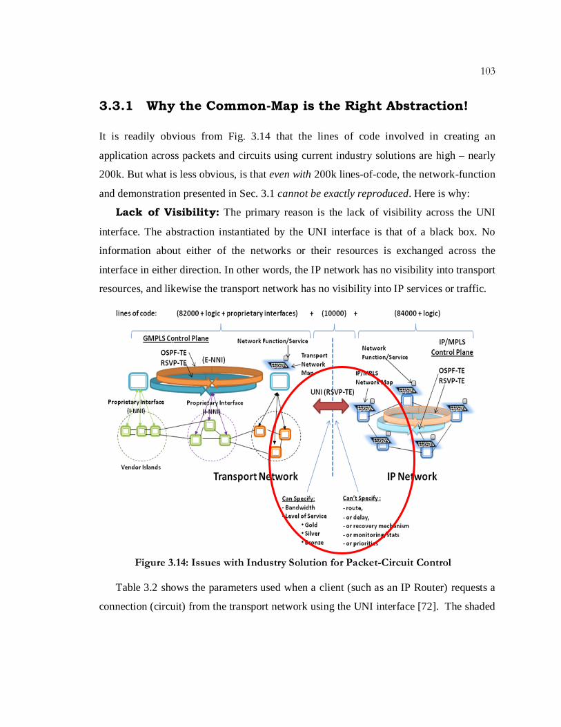
3.3.1 Why the Common-Map is the Right Abstraction!
It is readily obvious from Fig. 3.14 that the lines of code involved in creating an
application across packets and circuits using current industry solutions are high – nearly
200k. But what is less obvious, is that even with 200k lines-of-code, the network-function
and demonstration presented in Sec. 3.1 cannot be exactly reproduced. Here is why:
Lack of Visibility: The primary reason is the lack of visibility across the UNI
interface. The abstraction instantiated by the UNI interface is that of a black box. No
information about either of the networks or their resources is exchanged across the
interface in either direction. In other words, the IP network has no visibility into transport
resources, and likewise the transport network has no visibility into IP services or traffic.
Figure 3.14: Issues with Industry Solution for Packet-Circuit Control
Table 3.2 shows the parameters used when a client (such as an IP Router) requests a
connection (circuit) from the transport network using the UNI interface [72]. The shaded

104
CHAPTER 3. SIMPLICITY & EXTENSIBILITY OF ARCHITECTURE
parts of Table 3.2 offer some insight into the kind of requests that can be made. An
application in the packet-world can specify: traffic-parameters (which gets resolved into
required-bandwidth for a circuit provisioned in the transport network); a level-of-service;
and desired diversity of new circuit paths from existing paths originating from the same
UNI. The rest of the parameters in Table 3.2 identify the end-points of the
communication and other names, ids, labels and contracts associated with the connection.
What this basically means is that an application in the IP network cannot specify any
of the following: circuit-route, delay, recovery mechanism, recovery priority, pre-
emption, which circuits to monitor, or receive statistics from. But given full visibility, all
of these were possible and demonstrated with our control-architecture in Sec. 3.1.
Attributes Applicability Call/Conn Reference Source TNA Name (M) Cases 1 and 2 Call Section 10.13.1.1 Source Logical Port Identifier (M) Case 1 Connection Section 10.13.1.2 Source Generalized Label (O) Case 1 Connection Section 10.13.1.3 Destination TNA Name (M)
Cases 1 and 2 Call Section 10.13.1.1 Destination Logical Port Identifier (O-1, M-2) Cases 1 and 2 Connection Section 10.13.1.2
Destination Generalized Label (O-1, M-2) Cases 1 and 2 Connection Section 10.13.1.2 Local connection ID (M) Cases 1 and 2 Connection Section 10.13.1.4 Contract ID (O) Case 1 Call Section 10.13.4.1 Encoding Type (M) Cases 1 and 2 Call/Connection Section 10.13.2.1 Switching Type (M) Cases 1 and 2 Call/Connection Section 10.13.2.2 SONET/SDH, OTN or Ethernet traffic parameters (M)
Cases 1 and 2 Call/Connection Section 10.13.2.3
Directionality (O) Cases 1 and 2 Connection Section 10.13.2.4 Generalized Payload Identifier (O) Cases 1 and 2 Call Section 10.13.2.5
Section 10.13.2.5 Service Level (O-2)
Cases 1 and 2 Call Section 10.13.2.6 Diversity (M)
Cases 1 and 2 Call/Connection Section 10.13.3.1 Call Name (O-1,M-2) 1 Cases 1 and 2 Call Section 10.13.1.5 Bandwidth Modification Support(M) Cases 1 and 2 Connection Section 10.13.2.7
Table 3.2: UNI 2.0 Connection Setup Request Parameters (Table 5-11 from [72])
It is possible to define ‘some’ of the parameters mentioned above in an indirect way
through the Service Level. Such classes of service are designated Gold, Silver, or Bronze
and are pre-determined offline by the transport service provider. In other words, the
packet–network (or any other client) is limited to the exact service-level definitions the

105
transport network deems fit. This lack of visibility across the UNI interface coupled with
the pre-supposition of services absolutely kills programmability.
Further, the translation of these levels of service into actual circuit-characteristics
(route, delay, recovery etc.) is baked into the infrastructure via configuration of the UNI
interface on the transport-side; and their distribution to other elements in the transport
network by the dissemination mechanisms (GMPLS protocols and proprietary interfaces).
And so if the service requirements change from the packet-network, such change cannot
be handled by the transport network unless the new requirements exactly match with one
of the other pre-existing service specifications. If it does not, then manual-coordination is
required between IP and transport teams to draw up a new service definition and possibly
a new contract; and then to translate this new service to actual circuit characteristics,
potentially all the lines-of-code shown in Fig. 3.14 may need to be touched. Clearly this
hampers extensibility of services or network features.
Distributed Applications: Even if we assume that the philosophy behind the
UNI interface were to change and full visibility were allowed across the interface; it still
does not change the fact that introducing new network functionality is hard, due to the
distributed nature of their implementation coupled with the lack of a network-API.
Consider the challenges outlined below in implementing the network capability from
Sec. 3.1, despite the use of a hypothetical full-visibility UNI:
• The head-end of an MPLS tunnel would need to create traffic-type specific tunnels
(aggregates/bundles) and route them differently using DS-TE. But DS-TE only allows
reserving bandwidth for a single traffic type.
o One option could be that generic tunnels (with AutoRoute tuned off) may be used
with policy-routing via manual (or scripted) use of the CLI to create the policy.
o Or DS-TE can be changed to allow creating traffic-type tunnels for more than one
type. But this would involve changing the link-reservation mechanism in OSPF-
TE. And it would still need PBR to actually get specific-traffic into the tunnels.

106
CHAPTER 3. SIMPLICITY & EXTENSIBILITY OF ARCHITECTURE
• Once the traffic reaches a router at the edge of the transport network, it needs to be
mapped into circuits designed for the traffic. This router acts as the UNI client and
needs to know the requirements of each traffic-type:
o Either by configuration, which would be static;
o Or the tunnel-head-end has to have some way to communicate with this router,
which would mean a new protocol;
• Assuming that the UNI client router is aware of the service requirements, it needs full
visibility into the transport network. This requires the following:
o One choice is to eliminate the UNI and make the (former) UNI client router part
of the OSPF-TE instance running in the transport network. This is possible but
now the router runs two instances of OSPF-TE (one in the packet later and the
other in the circuit layer), which increases load on the router CPU.
o The other choice is to change the UNI and convey summary information of the
transport network to the router.
In either case the UNI client would need to deal with conflicts in its decisions for
services from the transport network with decisions made by other UNI-clients. It also
needs to deal with possibly conflicting requests from multiple MPLS tunnel head-
ends at the same time.
• Also monitoring of these circuits can by the management systems (NMS/EMS) today
and theoretically it is possible to tie this monitoring capability to the CSPF algorithm
running in the UNI client router, to re-route bandwidth based on usage. This would
require change to the UNI or the use of a new protocol.
• Likewise such tie-ins can also be created with glue-code to develop a programmatic
way for alarm generation (when network-failure events happen) to trigger a CSPF
calculation and subsequent prioritized protection/re-routing. Again separate protocols
and APIs would have to be used.

107
From the above discussion we see that full visibility across packets and circuits is
essential to replicate our control-function, but even with full-visibility, a host of other
glue-code and patchwork is needed to existing protocols, together with possibly some
new protocols. And so it is easy to see that the current industry solution lacks ease of
extensibility.
Common-Map Abstraction: Our SDN based solution is more easily extensible
to the creation of new services or network functions (Fig. 3.15) because it gives full
visibility of both networks to the network application in a programmatic way. It does not
involve configured, presupposed/pre-baked service choices, mappings and CLI based
policy rule-insertions. All of these can be dynamic and programmatic. And the common-
map abstraction abstracts away the distribution mechanism from the applications,
allowing them to be implemented in a centralized way with a well-defined and rich
network-API.
For these reasons we believe the common-map abstraction, instead of the UNI, is the
right abstraction for implementing simple and extensible services over packets and
circuits. In the next section we give further validation of the extensibility of our
architectural solution.
Figure 3.15: Simplicity & Extensibility of Unified Control Architecture

108
CHAPTER 3. SIMPLICITY & EXTENSIBILITY OF ARCHITECTURE
3.3.2 Other Applications with Packets and Circuits
In Section 3.1, we showed an example of our control architecture enabling network-
capabilities that are end-user application or service aware. Such end-user services can be
related to the traffic-type (voice, video, http, ftp) or some higher order application (like
data-backup, live-TV, mobility). The network-capabilities for such end-user services
include application-aware-routing, recovery and service-guarantees; all which can be
easily performed with dynamic circuit-flows working closely with packet-flows. In this
section, we briefly detail three other capabilities across packets and circuits made
possible by our control architecture.
Dynamic Packet Links: IP topologies today are static. IP links over the wide-
are pre-planned and put in-place using static-circuits in the underlying transport network.
Information about link-state is carried by distributed link-state routing protocols to every
router in the network. Routers make forwarding decisions based on SPF calculations
performed on the map they create from the link-state information. Any change to the
network-topology (say from link-failures) results in routing-protocol re-convergence,
where every router re-converges to a consistent view of the network. Convergence is
considered disruptive. Disappearing or re-appearing links require SPF calculations in
every router, potentially re-routing packet flows everywhere in the network. Thus it is not
surprising that IP links are always static.
But an OpenFlow based network eliminates the need for distributed routing protocols
within the Controller’s domain, as the switches do not make routing decisions. There are
two advantages here:
1. With centralized-decision making, dynamic packet-link creation is convergence-free.
We can create packet-links where none existed (using underlying dynamic circuits).
And such newly created links no longer require distributed-routing protocol
convergence, as routers no longer make routing decisions. And so circuits can change

109
as dynamically as needed to bring up/down packet-links in an IP-topology without
fearing routing-protocol meltdown.
2. We can choose which flows to effect and which flow routes to leave unchanged. In
sharp contrast to today’s IP networks, none of these dynamic link-changes are
disruptive to existing packet flows elsewhere in the network. The controller makes
the decision of creating/changing/ deleting a link, and it only affects the flows chosen
for the link and nowhere else.
Figure 3.16: Dynamic Packet-Links
Fig. 3.16 shows how packet-links can be dynamically created and removed by
redirecting underlying circuits (not shown) between three packet-switches, using the
same set of packet-interfaces on each switch. The capability to create new packet-links
can have several use-cases. One could involve relieving congestion between two routers.
Other cases could involve time-of-day or application needs; where say between two data-
centers depending on the time-of-day, or some bandwidth hungry application like data-
backup, there is a need for more bandwidth. But at other times those same circuits could
be re-routed away to buttress bandwidth needs elsewhere. This way expensive WAN
bandwidth is shared between router-ports; bandwidth can be flexibly available where and
when needed; and all of this can be done programmatically.
Variable Bandwidth Packet Links: There are two ways to consider packet-
links that have variable bandwidth. One of these, shown in Fig. 3.17, is a variation of the
dynamic links scheme proposed earlier. Here instead of using circuits to create new
packet-links, existing packet links have their underlying circuit-bandwidth re-directed
over the WAN.

110
CHAPTER 3. SIMPLICITY & EXTENSIBILITY OF ARCHITECTURE
Consider the 10GE router links in Fig. 3.17a. Instead of being supported by 10Gbps
circuits in the transport network, one of them is supported by less (say 5 Gbps), while the
other is supported at full line-rate. The lower part of 3.17a shows the same routers but
also shows the transport equipment they are connected to. So when the lower-provisioned
router-interface needs more bandwidth, circuits could be re-routed or created to support
it. As an example of the former, in Fig. 3.17b, circuit-bandwidth has been re-routed from
the previously fully provisioned router-link. Alternately, circuits could be created from
elsewhere to support both router interfaces at full line rate, but only for a period of time;
this is essentially a pay-per-use model for expensive WAN bandwidth.
Figure 3.17: Variable Bandwidth Packet Links – Type I
The other kind of variable bandwidth packet-link involves dividing a packet link over
multiple circuits of variable bandwidth in the transport layer. In Fig. 3.18, the same
(virtual) packet-link uses two circuits (of variable bandwidth) to make up the full-line-
rate of the router interfaces.
(a) (b)

111
Figure 3.18: Variable Bandwidth Packet Links – Type II
Use-cases for doing so may include:
• load-balancing over different paths in the transport network;
• routing multiple circuits over diverse paths to support the same packet-link, so that
the packet-link never goes down – if one of the circuit paths fail the other takes over
with full line rate;
• Or as we showed in Sec 3.1.2, different services or traffic can be supported by
different circuits (with different characteristics) over the same packet-link (i.e the
same packet-interfaces).
Unified Routing: This particular application takes a look at how routing can be
performed, were the packet and circuit switched networks considered part of the same
‘layer’. In other words if the common-map were to be constructed based on the right-side
of Fig. 2.12. Note that in this de-layered view, packet and circuit switches appear as a sea
of switches connected by physical links (no virtual-links).
We show a way to do simple shortest-path IP routing; that does not resort to any
complicated CSPF algorithms or traffic-engineering mechanisms; and yet, is aware of
and accounts for network state and resources. Consider Fig. 3.19 - three packet switches
(P) interconnected by existing circuit flows established on the circuit switches (C).
Contrary to IP routing today, the connections between the packet-switches have costs
assigned to them in a piecewise manner.

112
CHAPTER 3. SIMPLICITY & EXTENSIBILITY OF ARCHITECTURE
As an example, the circuits have costs inversely proportional to the bandwidth of the
path, and directly proportional to the propagation delay and usage of the path. This way,
higher the bandwidth of the circuit, or shorter the path, the cost of the circuit-path is
lower. These parameters are fixed. However the usage parameter is variable and
dependent on the actual traffic traversing the circuit flow. Higher the usage: the greater is
the cost. As new packet flows get added to circuit flows, the usage (and cost) increases;
discouraging the use of the circuit and potentially avoiding future congestion by making
alternate (less-utilized) paths more attractive. As packet flows expire and usage goes
down, the cost decreases.
Figure 3.19: Unified Routing in a De-layered Packet-Circuit Network
The C to P connections also have costs assigned to them in a way that penalizes the
use of the link. Let us see how – a packet-flow from Pa to Pc can take the direct path
from Pa to Pc (via Ckt 3) or the indirect one that transits Pb. Assuming that the costs of
the circuits sum up equally (ckt3 = cost of ckt1+cost of ckt2), the direct path would be
preferred over the indirect path due to the penalty incurred in transiting Pb. So the packet
flow gets routed over ckt3. But as circuit flow costs are variable, as usage increases on
ckt. 3, the indirect path becomes more attractive.
To have ‘usage’ be reflected in the ‘cost’ used for an SPF calculation, allows efficient
and yet simple routing. Unlike regular IP networks, the use of variable link-costs do not
Ckt 1 Ckt 3
Ckt 2
Pa
Pb
Pc
Cb Cc
Ca

113
imply that packet flows already established in the network are effected (rerouted), as
again the controller may re-route only the new flows entering the network, while leaving
existing flows untouched.
To summarize, we provided further validation of the extensibility of our control
architecture by showing examples of how packets can interact with dynamic circuits to
provide varied services, beyond the ones discussed in Sec. 3.1. It is worth noting that
most likely these services cannot be implemented with existing industry solutions due to
lack of visibility between packets and circuit domains. But even if these examples could
be implemented with existing industry-based control solutions, the sheer number of
protocols, their distributed nature, and their potentially dangerous interactions, make the
solutions so complex that no service provider would want to use them in their network.
3.4 Deployment Challenges & Proposed Solutions
As final validation of the simplicity and extensibility of our work, we propose solutions
based on our control architecture to three deployment challenges faced by any unified
control solution for packet and circuit networks†.
Challenge #1: Reluctance of network operators of packet and circuit networks to
share information with each other. We noted that UNI interface blocks all visibility at the
boundary between IP and transport networks. The interface merely implements the
philosophy of not wanting to share information across network boundaries. This remains
an issue even with our solution (presented thus far). The operators of these networks
simply do not wish to share information about their networks. And this problem is more
acute in the case where the networks are owned by different businesses (analogous to AS-
to-AS communications in the Internet where internal AS topology is not shared across
AS boundaries). How then to create a common-map across packets and circuits?
Proposed Solution – Slicing & Transport Switching-as-a-Service:
With reference to Fig. 3.1, so far we have only talked about the Net OS and OpenFlow as
† As an aside, note that the common-map abstraction for packet and circuit switching, applied to other network contexts such as data-centers and enterprise networks may not have these deployment challenges.

114
CHAPTER 3. SIMPLICITY & EXTENSIBILITY OF ARCHITECTURE
part of the unified control plane (UCP) that supports our abstractions. We now present
the slicing-plane as a key component of the UCP that helps us meet several challenges.
In slicing, a new control layer is placed between the underlying switches and the
controller-layer. This new control layer (the slicing layer) partitions the underlying data-
plane into multiple slices, where each slice can then be put under the control of different
controllers. An example of the implementation of the slicing-plane is the FlowVisor [50].
In the context of packet and circuit networks, a slice is defined as the combination of
bandwidth and circuit-switching resources. It is worth noting that transport networks
today also provide slices of their network to ISPs. However such slices only provide
static bandwidth with no control over that bandwidth (where by control we mean the
ability to route it differently, change its size etc.). Such static bandwidth is often referred
to as a dumb-pipe in the industry.
However our slice definition includes bandwidth plus the ability to manipulate it via
control over switching resources in that slice [11]. Circuits in a slice already provide
data-plane isolation between slices. The slicing plane crucially provides control-plane
isolation. With the slicing plane under the transport network operator’s control, the
control of each slice can be turned over to the ISP that purchases the slice (Fig 3.14).
Figure 3.19: Slicing the Transport Network [11]

115
The slicing-plane ensures that no-ISP can maliciously or inadvertently control any
transport switching resources that are not in its slice of the transport network. The slicing
plane achieves this control-isolation by monitoring the messages between the switches
and the controllers and checking them against the slice-policy. It can either passively
relay the messages or translate them where appropriate. Or it can reject the messages if
they are in violation of the slice-policy.
Slicing enables the ISP to run the common-map abstraction in its controller. This
controller has view of the packet switches that belong to the ISP. It also has view of the
circuit-switching-resources that are part of its slice of the transport network, thereby
enabling the ISP to create a common-map abstraction across packets and circuits. In other
words the ‘slice’ is the common-map that presents the same map-abstraction and
network-API discussed in Chapters 1 and 2.
Note that this view of the circuit-switching-resources in the transport network is
restricted to only the slice that the ISP has purchased and not the entire transport network.
It thus overcomes the lack-of-information-sharing seen in packet and circuit networks
today, by sharing only a part of the information (instead of divulging information about
the entire-network). And the transport network carrier has incentive to share this partial
information about the slice because it enables a new service (new revenue opportunities).
Today transport networks share no information and offer only static-bandwidth (dumb
pipes). With slicing, transport networks can offer slices which include bandwidth and
isolated transport-switch control to ISPs, thereby offering a new service [73] †.
It is worth noting that in the absence of such sharing models, the only option is to
share no information, leading to interfaces between IP and transport networks like the
UNI. And we have shown issues with such interfaces in the previous sections, which we
believe are key reasons behind the commercial-failure of the UNI (and GMPLS). But
with our proposed technical solution based on slicing, and our economic solution of
offering transport slices-as-a-service, we believe the practical-challenge of information
sharing can be solved.
† The creation of the slice or modifications to what falls within a slice requires an out-of-band channel (either manual or automated), and is outside the scope of OpenFlow. Once the slice is created, our control architecture provides control over switching resources in the slice and control-plane isolation between multiple slices.

116
CHAPTER 3. SIMPLICITY & EXTENSIBILITY OF ARCHITECTURE
Challenge #2: Conservative nature of transport network operators towards
automated control planes. Transport network operators would like to respond faster and
provide more dynamic services to meet their client needs, but loathe giving up precise
manual control over the way traffic is routed over their network to a software control
plane, irrespective of how intelligent that control plane may be [26]. Is there a way that
allows decades of established procedures to co-exist with new ways to deploy services
and operate the network?
Proposed Solution – Slicing based Gradual Adoption Path: Again it
is the slicing plane that provides a gradual adoption path, that can let established
procedures co-exist with new ones. Consider this – the transport network operator
initially slices only a small part (5%) of its network and hands over control to an ISP’s
controller through its slicing plane. As long as the slicing plane guarantees isolation of
the slices in both the data and control plane, the transport network operator retains
control over the unsliced part of the transport network which can still be run manually,
using established procedures, as it is today. Meanwhile the ISP is free to use whatever
automated intelligent control algorithms it may desire in its isolated slice of the transport
network (any of the examples from the previous section). Over time as more confidence
is gained in the slicing framework, more parts of the transport network could be sliced
and offered as a service to other ISPs. It is worth noting that GMPLS provides no such
means for such flexible and gradual adoption.
Challenge #3: A final challenge faced by any unified control plane solution for
packet and circuit networks, involves the conservative nature of IP network operators
towards increasing load on distributed routing protocols.
When the same business owns both networks, a single instance of a distributed
routing protocol could disseminate information on packet and circuit link state leading to
the creation of a common-map. However this is not done today simply because IP
network operators loathe exposing their distributed link-state routing protocols to

117
transport network link attributes in fear of increasing load on router-CPUs and de-
stabilizing their network. Let’s see why.
Distributed link-state routing protocol like OSPF or IS-IS have convergence and
stability issues if network state changes too fast or too often. Stability in a distributed
routing protocol can be defined in several ways:
• A clear indicator is the network convergence time i.e. the times taken by all the
routers to return to steady state operation after a change in network state.
Convergence time has a propagation component, which is the time taken for the new
information to be disbursed via the IGP to all the routers so they can update their link-
state databases; and a re-route component where new SPTs are calculated or TE paths
are re-routed if necessary. Clearly a low convergence time indicates a stable network.
• A related parameter often is the number of route flaps, which refer to routing table
changes in a router in response to change in network state. A large number of flaps in
a short time can adversely affect network stability.
• But by far the key indicator of stability is the routing load on switch CPUs. This is a
measure of how much time a router spends in processing control packets from the
routing protocol. If there are frequent changes in the network state, and update
messages are sent frequently (sometimes called churn), the router CPU may spend a
lot of time doing route calculations; this in turn may lead to ingress CPU queues
getting filled and incoming packets getting dropped (including hellos); dropping
keep-alives may cause timeouts and dropping of routing- adjacencies; which again
leads to more control packets getting generated and greater routing load. This
cascading effect results in longer convergence times, routing loops, more route flaps,
greater CPU loads, and in the worst case network meltdown [74].
To avoid routing protocol instability, router vendors apply several damping
mechanisms to keep things under control. For example, the router is informed of bad
news (link down) by the link layer fast, but good news (link up) is delayed (many
seconds) to avoid potential link flaps. The generation of link update messages and the
118
CHAPTER 3. SIMPLICITY & EXTENSIBILITY OF ARCHITECTURE
occurrence of SPT recalculations are throttled by dynamic timers that exponentially
increase their times during periods of instability to prevent processor meltdown.
It is therefore easy to see that distributed routing protocols are fragile, and require
careful tuning and tweaking to keep them stable. Changes that are too fast or too often are
not tolerated and carefully damped. This is the fundamental reason why IP networks
today do not support dynamic links or dynamic link weights [75].
And so to extend OSPF/IS-IS and use it in a dynamic circuit network with its effect
being felt by the same or another instance of the distributed routing protocol in the packet
network is simply dangerous and unwarranted. Unfortunately, this is exactly what
GMPLS proposes.
Our Solution – Elimination of Distributed Routing Protocols: We
have mentioned several times before that distributed routing protocols are unnecessary in
an SDN controller’s domain. The elimination of distributed routing protocols is a natural
consequence of the adoption of SDN ideas and OpenFlow to form our unified control
architecture. But it is worth pointing out that in the context of packet and circuit network
control, we find that SDN/OpenFlow has the direct benefit of removing one of the key
hindrances to the deployment of dynamic circuit switching in today’s networks; by no
longer being subject to a) stability issues of dynamic routing protocols, and b) limited
processing powers on switch CPUs.
3.5 Summary
The goal of this chapter was to validate the simplicity and extensibility claims we made
for our architectural solution. For the simplicity claim, we took a new and fairly involved
network capability; implemented it with our control architecture; and then compared our
implementation to our best guess of what it would take to implement the same functions
using current industry-standard solutions for packet-circuit control.
119
We performed a lines-of-code analysis and found our solution to be two orders-of-
magnitude simpler. We provide qualitative architectural insights into why our solution
takes far less line-of-code. And while our work is not production-ready, two orders of
magnitude difference gives us confidence that even production quality code in our
architecture would be much simpler.
Next we reasoned that even with two orders of magnitude more code, current industry
solutions would not be able to exactly replicate our work. We believe it is because of two
main reasons: the use of the UNI interface which results in loss of visibility across packet
and circuit networks; and the implementation of services as distributed systems which are
tied to the distribution mechanisms. We explained how our common-map abstraction
does not suffer from these limitations; and therefore not only is it simple to implement
control-functions across packet and circuits; it is easy to introduce new functionality, or
change existing functionality in the network just as easily; thereby validating our
extensibility claim. As further justification of extensibility, we described three other
applications enabled at the packet-circuit boundary by our unified-control architecture.
Finally we detailed deployment issues faced by any control-solution for common
packet-circuit control. We proposed the use of ‘slicing’, a key component of our control
architecture, to overcome these challenges. For transport network operators, slicing is a
technical solution that a) provides an economic-incentive (a new service) for sharing
information with ISPs, which can then allow the latter to have visibility across packets
and circuits when creating the common-map; and b) slicing eases the path to gradual-
adoption of our control architecture – a key requirement for the adoption of any new
control technology.