chapter 3 underlying technology - kennesaw state university
TRANSCRIPT

TCP/IP Protocol Suite 1 Copyright © The McGraw-Hill Companies, Inc. Permission required for reproduction or display.
Chapter 3
Underlying
Technology

TCP/IP Protocol Suite 2
Chapter
Outline
TCP/IP Protocol Suite 3
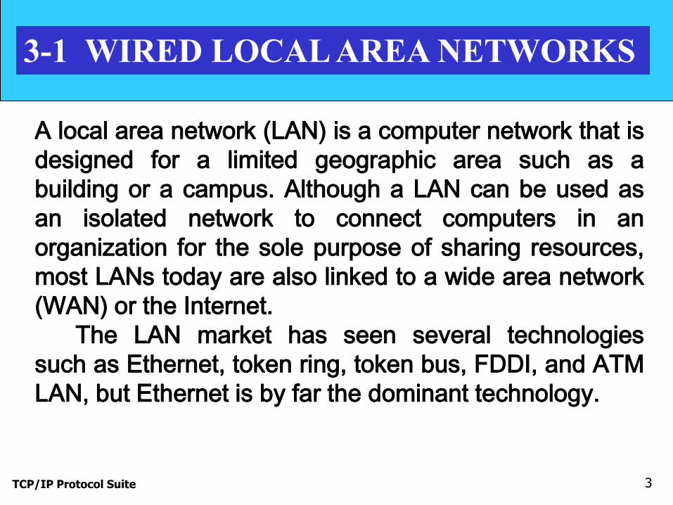
3-1 WIRED LOCAL AREA NETWORKS
A local area network (LAN) is a computer network that is
designed for a limited geographic area such as a
building or a campus. Although a LAN can be used as
an isolated network to connect computers in an
organization for the sole purpose of sharing resources,
most LANs today are also linked to a wide area network
(WAN) or the Internet.
The LAN market has seen several technologies
such as Ethernet, token ring, token bus, FDDI, and ATM
LAN, but Ethernet is by far the dominant technology.
TCP/IP Protocol Suite 4
Topics Discussed in the Section
IEEE Standards Project 802
Enable intercommunication among equipment from a
variety of manufacturers
Specify functions of the physical layer and the data
link layer of major LAN protocols

TCP/IP Protocol Suite 5
Figure 3.1 IEEE standard for LANs

TCP/IP Protocol Suite 6
Topics Discussed in the Section
Frame Format

TCP/IP Protocol Suite 7
Figure 3.2 Ethernet Frame

TCP/IP Protocol Suite 8
Figure 3.3 Maximum and minimum lengths

TCP/IP Protocol Suite 9
Minimum length: 64 bytes (512 bits)
Maximum length: 1518 bytes (12,144 bits)
Note

TCP/IP Protocol Suite 10
Topics Discussed in the Section
Addressing
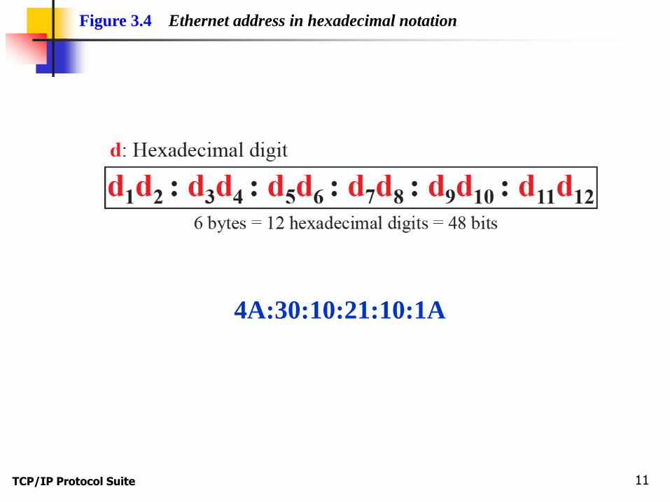
TCP/IP Protocol Suite 11
Figure 3.4 Ethernet address in hexadecimal notation
4A:30:10:21:10:1A

TCP/IP Protocol Suite 12
Addressing
A source address is always a unicast address
The destination address can be unicast, multicast, or
broadcast

TCP/IP Protocol Suite 13
Figure 3.5 Unicast and multicast addresses
multicast: 1unicast: 0
The least significant bit of the first byte
defines the type of address.
If the bit is 0, the address is unicast;
otherwise, it is multicast.

TCP/IP Protocol Suite 14
The broadcast destination address is a
special case of the multicast address
in which all bits are 1s.
Note

TCP/IP Protocol Suite 15
Define the type of the following destination addresses:
a. 4A:30:10:21:10:1A
b. 47:20:1B:2E:08:EE
c. FF:FF:FF:FF:FF:FF
Solution To find the type of the address, we need to look at the second
hexadecimal digit from the left. If it is even, the address is unicast. If it
is odd, the address is multicast. If all digits are F’s, the address is
broadcast. Therefore, we have the following:
a. This is a unicast address because A in binary is 1010 (even).
b. This is a multicast address because 7 in binary is 0111 (odd).
c. This is a broadcast address because all digits are F’s.
Example 3.1

TCP/IP Protocol Suite 16
Show how the address 47:20:1B:2E:08:EE is sent out on line.
Solution The address is sent left-to-right, byte by byte; for each byte, it is
sent right-to-left, bit by bit, as shown below:
Example 3.2
← 11100010 00000100 11011000 01110100 00010000 01110111
TCP/IP Protocol Suite 17
Topics Discussed in the Section
Ethernet Evolution
Standard Ethernet
Fast Ethernet
Gigabit Ethernet
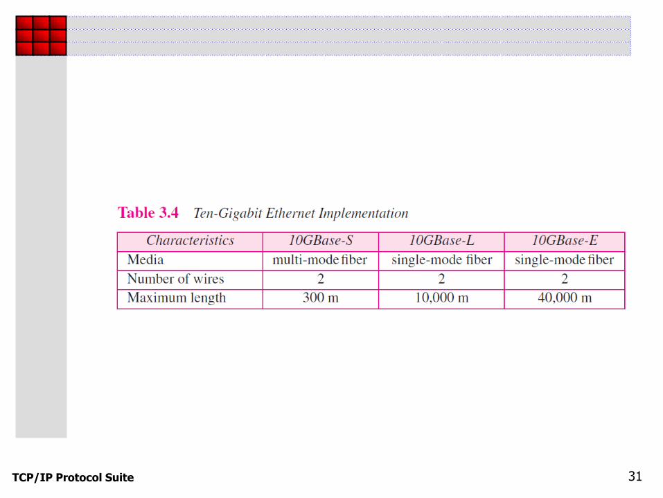
Ten-Gigabit Ethernet

TCP/IP Protocol Suite 18
Figure 3.6 Ethernet evolution through four generations
TCP/IP Protocol Suite 19
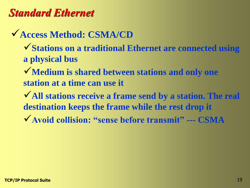
Standard Ethernet
Access Method: CSMA/CD
Stations on a traditional Ethernet are connected using
a physical bus
Medium is shared between stations and only one
station at a time can use it
All stations receive a frame send by a station. The real
destination keeps the frame while the rest drop it
Avoid collision: “sense before transmit” --- CSMA

TCP/IP Protocol Suite 20
Figure 3.7 Space/time model of a collision in CSMA
T i m e T i m e
B A C D
B starts
at time t1
Area where
A’s signal exists
C starts
at time t2
Area where
B’s signal exists
Area where
both signals exist
TCP/IP Protocol Suite 21
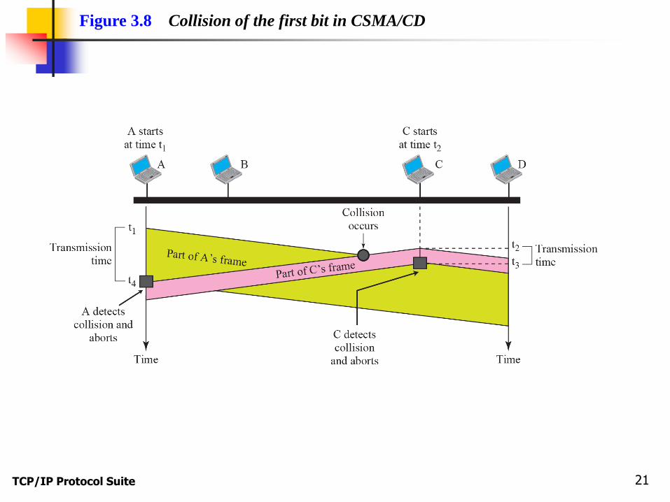
Figure 3.8 Collision of the first bit in CSMA/CD

TCP/IP Protocol Suite 22
In the standard Ethernet, if the maximum propagation time is
25.6 μs, what is the minimum size of the frame?
Solution
The frame transmission time is Tfr = 2 × Tp = 51.2 μs. This
means, in the worst case, a station needs to transmit for a
period of 51.2 μs to detect the collision. The minimum size of
the frame is 10 Mbps × 51.2 μs = 512 bits or 64 bytes. This is
actually the minimum size of the frame for Standard Ethernet,
as we discussed before.
Example 3.3
TCP/IP Protocol Suite 23
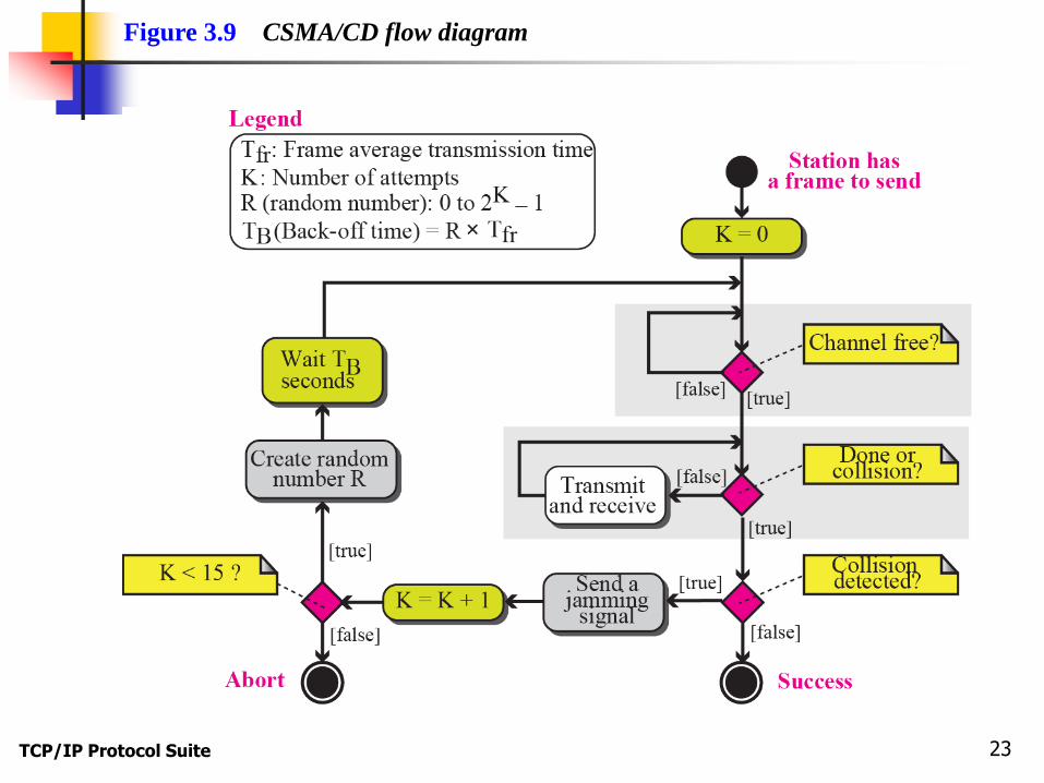
Figure 3.9 CSMA/CD flow diagram
TCP/IP Protocol Suite 24

TCP/IP Protocol Suite 25
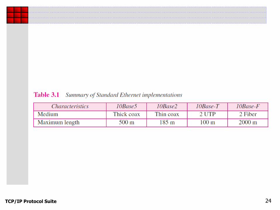
Figure 3.10 Standard Ethernet implementation

TCP/IP Protocol Suite 26

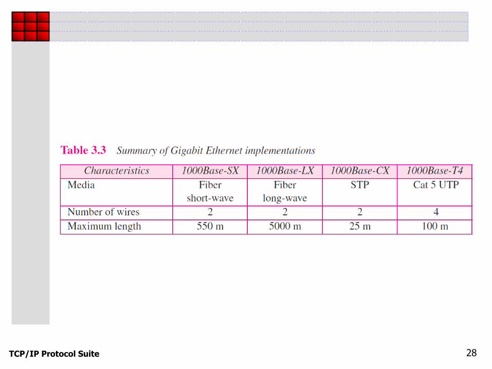
TCP/IP Protocol Suite 27
Figure 3.11 Fast Ethernet implementation
TCP/IP Protocol Suite 28
TCP/IP Protocol Suite 29
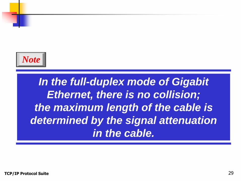
In the full-duplex mode of Gigabit
Ethernet, there is no collision;
the maximum length of the cable is
determined by the signal attenuation
in the cable.
Note
TCP/IP Protocol Suite 30
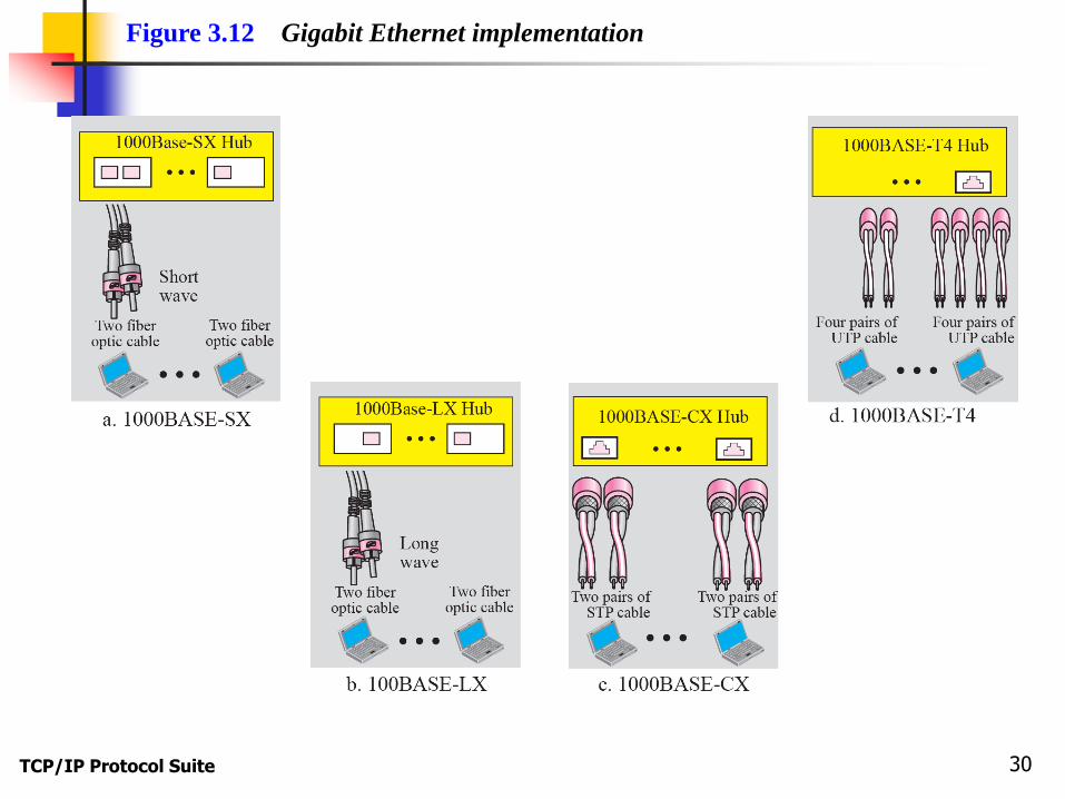
Figure 3.12 Gigabit Ethernet implementation
TCP/IP Protocol Suite 31

TCP/IP Protocol Suite 32
3-2 WIRELESS LANS
Wireless communication is one of the fastest
growing technologies. The demand for connecting
devices without the use of cables is increasing
everywhere. Wireless LANs can be found on college
campuses, in office buildings, and in many public
areas. In this section, we concentrate on two
wireless technologies for LANs: IEEE 802.11
wireless LANs, sometimes called wireless Ethernet,
and Bluetooth, a technology for small wireless LANs.
TCP/IP Protocol Suite 33
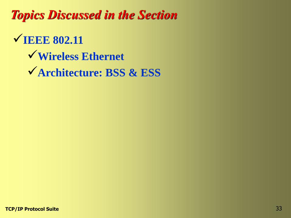
Topics Discussed in the Section
IEEE 802.11
Wireless Ethernet
Architecture: BSS & ESS

TCP/IP Protocol Suite 34
Figure 3.13 Basic service sets (BSSs)

TCP/IP Protocol Suite 35
Figure 3.14 Extended service sets (ESSs)

TCP/IP Protocol Suite 36
Topics Discussed in the Section
Access Method: CSMA
MAC protocol: CSMA/CA

TCP/IP Protocol Suite 37
All other stations
• • •
Source Destination
TimeTime Time Time
Figure 3.16 CSMA/CA and NAV
DIFS
SIFS
RTS1
SIFS
CTS 2
SIFS
Data3
ACK 4
NAV
(No carrier sensing)

TCP/IP Protocol Suite 38
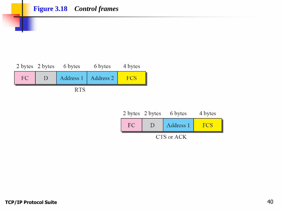
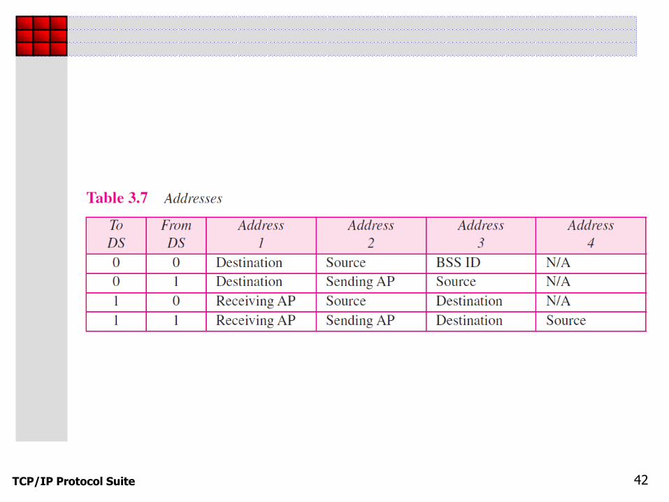
Figure 3.17 Frame format

TCP/IP Protocol Suite 39
TCP/IP Protocol Suite 40
Figure 3.18 Control frames

TCP/IP Protocol Suite 41
TCP/IP Protocol Suite 42

TCP/IP Protocol Suite 43
Figure 3.19 Hidden station problem
TCP/IP Protocol Suite 44
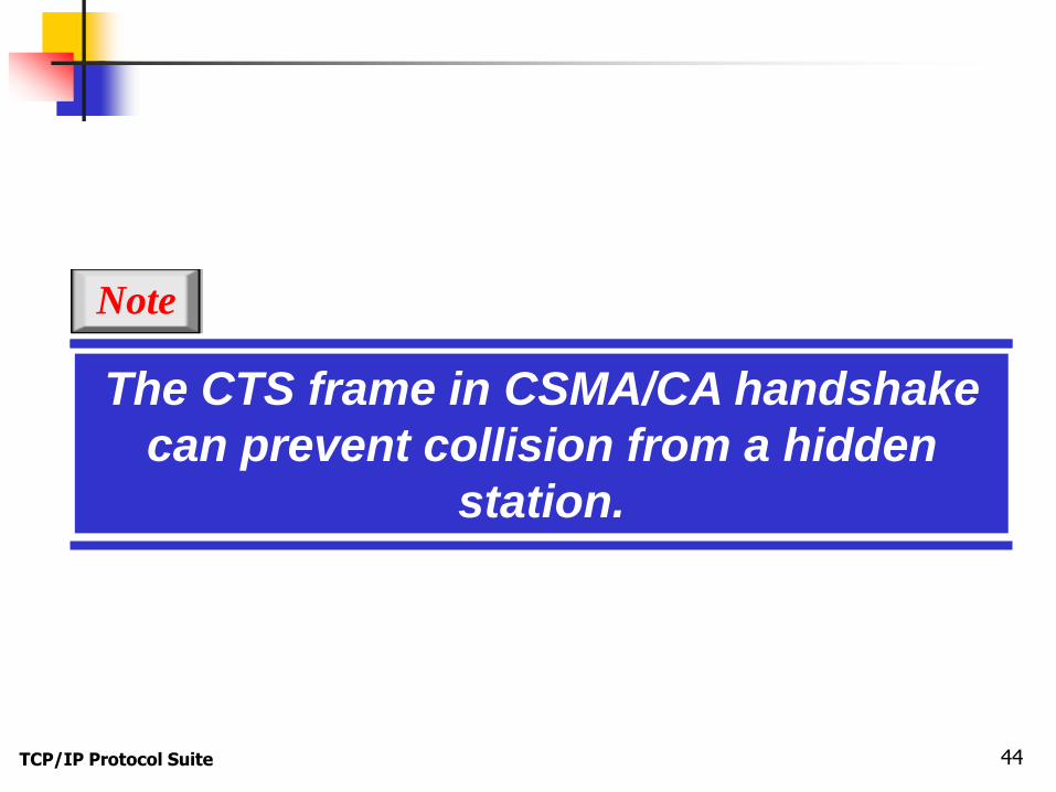
The CTS frame in CSMA/CA handshake
can prevent collision from a hidden
station.
Note
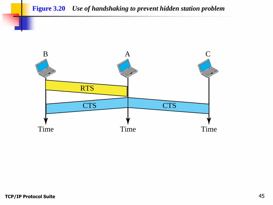
TCP/IP Protocol Suite 45
Time Time Time
AB C
Figure 3.20 Use of handshaking to prevent hidden station problem
RTS
CTS CTS

TCP/IP Protocol Suite 46
Figure 3.21 Exposed station problem
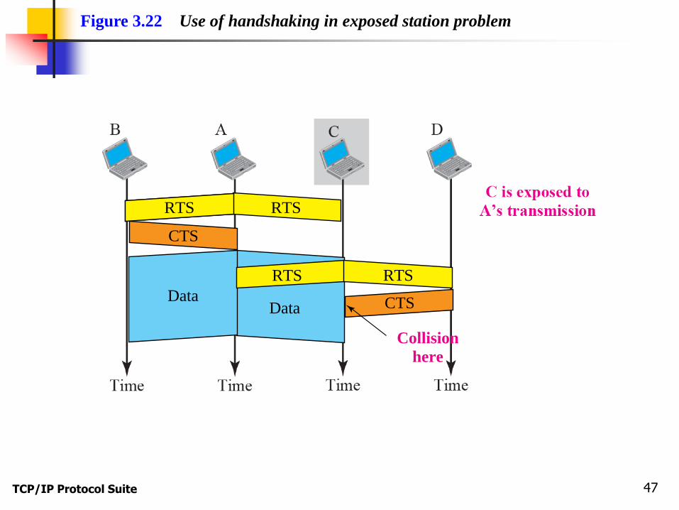
TCP/IP Protocol Suite 47
Figure 3.22 Use of handshaking in exposed station problem
RTS RTSRTS
CTS
DataData
RTSRTS
Collision
here
CTS

TCP/IP Protocol Suite 48
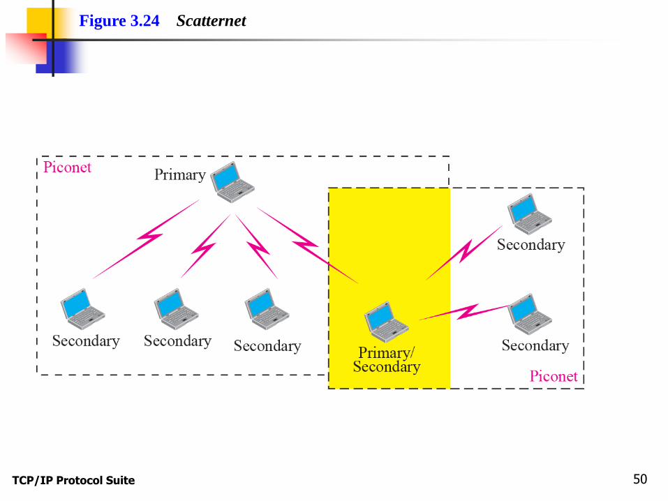
Topics Discussed in the Section
Bluetooth: small wireless LAN
Connect devices of different functions such as
telephone, notebooks, computers, cameras, printers,
and so on.
Piconet
Scatternet

TCP/IP Protocol Suite 49
Figure 3.23 Piconet
TCP/IP Protocol Suite 50
Figure 3.24 Scatternet
TCP/IP Protocol Suite 51
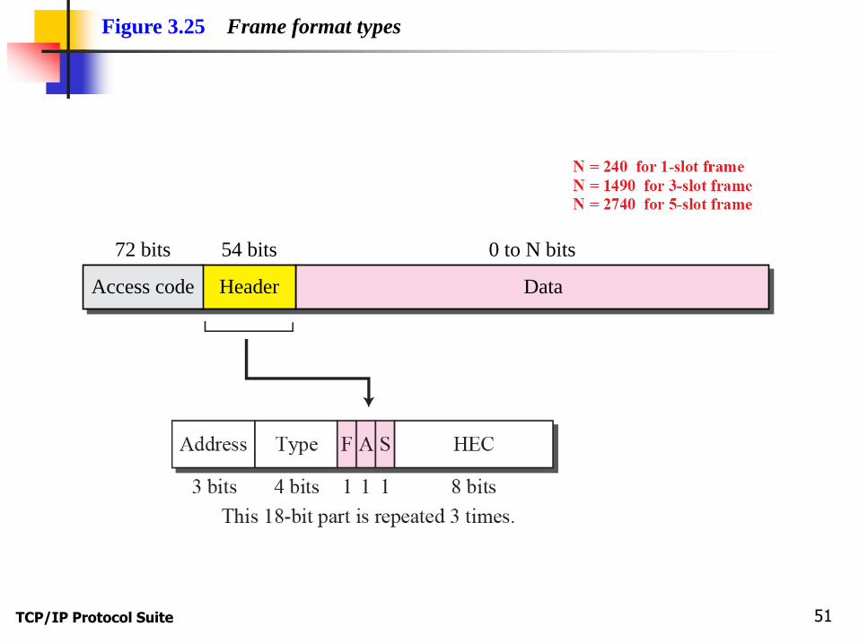
72 bits 54 bits 0 to N bits
Access code Header Data
Figure 3.25 Frame format types

TCP/IP Protocol Suite 52
3-3 POINT-TO-POINT WANS
A second type of network we encounter in the
Internet is the point-to-point wide area network. A
point-to-point WAN connects two remote devices
using a line available from a public network such as
a telephone network. We discuss traditional modem
technology, DSL line, cable modem, T-lines, and
SONET.
TCP/IP Protocol Suite 53
Topics Discussed in the Section
65K Modems

TCP/IP Protocol Suite 54
Figure 3.26 56K modem
Uploading,quantization noise
Downloading,no quantization noise

TCP/IP Protocol Suite 55
Topics Discussed in the Section
DSL Technology
ADSL
VDSL
HDSL
SDSL
TCP/IP Protocol Suite 56
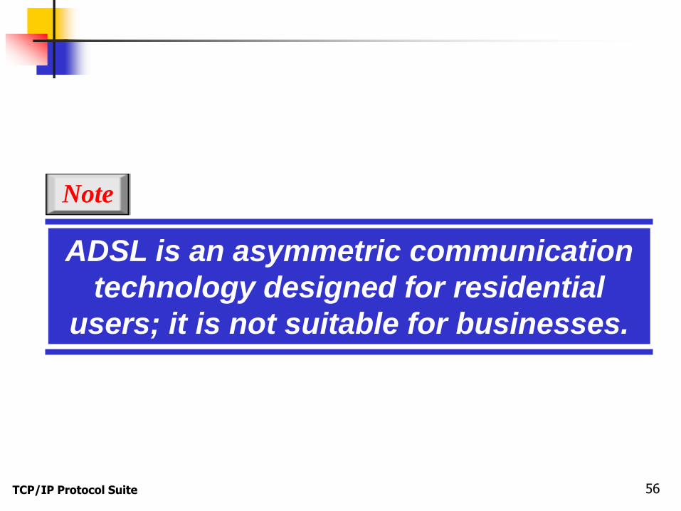
ADSL is an asymmetric communication
technology designed for residential
users; it is not suitable for businesses.
Note
TCP/IP Protocol Suite 57
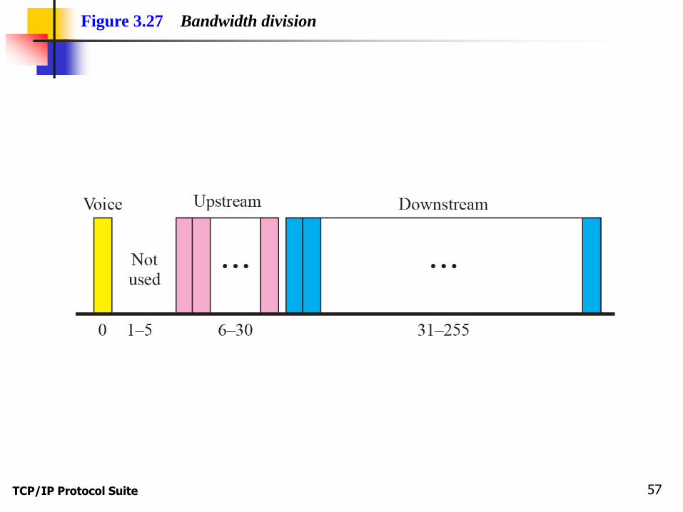
Figure 3.27 Bandwidth division

TCP/IP Protocol Suite 58
Figure 3.28 ADSL and DSLAM
TCP/IP Protocol Suite 59
Topics Discussed in the Section
Cable Modem

TCP/IP Protocol Suite 60
Figure 3.29 Cable bandwidth

TCP/IP Protocol Suite 61
Figure 3.30 Cable modem configuration

TCP/IP Protocol Suite 62
Topics Discussed in the Section
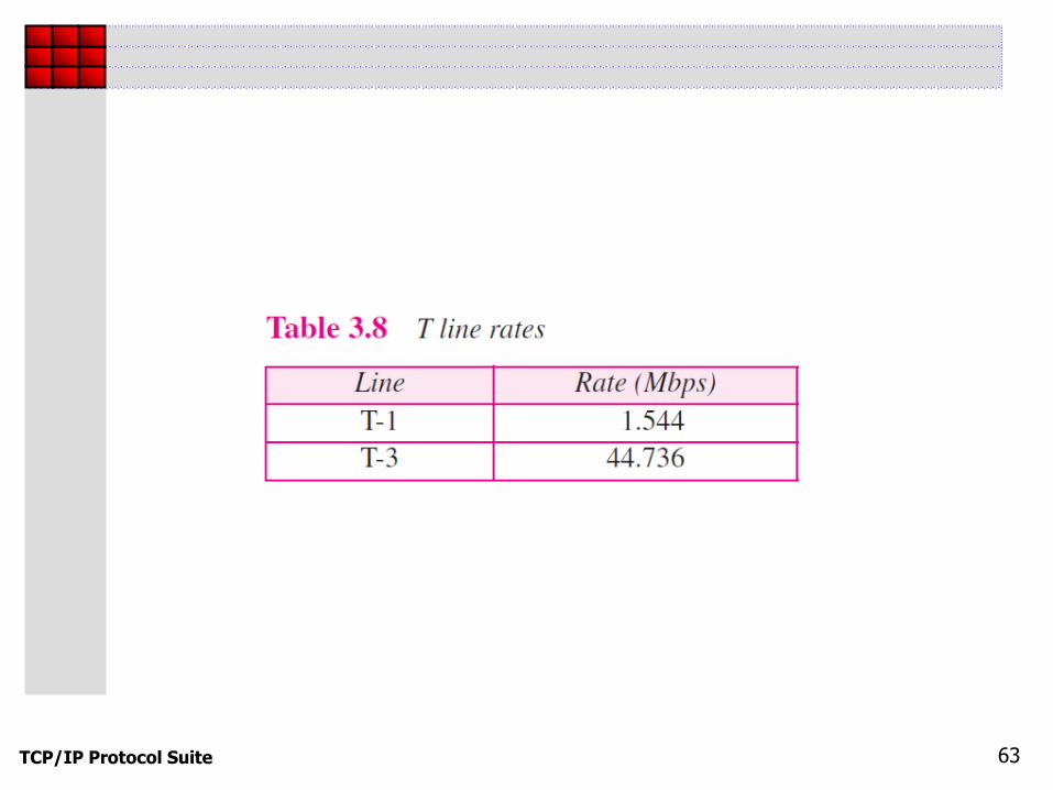
T Lines
T-1 Line
T-3 Line
TCP/IP Protocol Suite 63

TCP/IP Protocol Suite 64
Topics Discussed in the Section
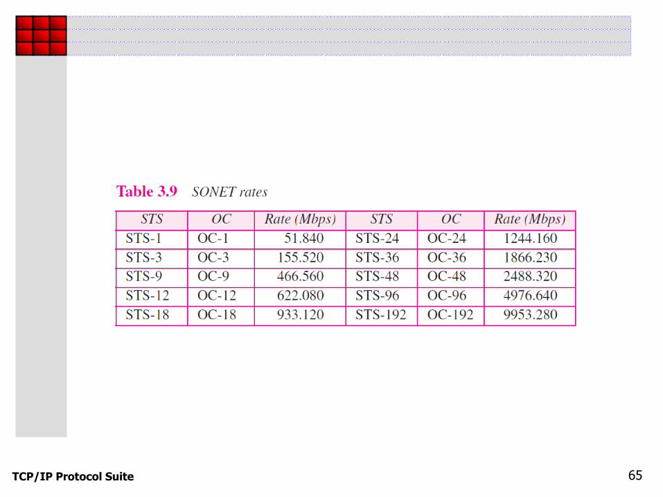
Synchronous Optical Network (SONET)
TCP/IP Protocol Suite 65

TCP/IP Protocol Suite 66
Topics Discussed in the Section
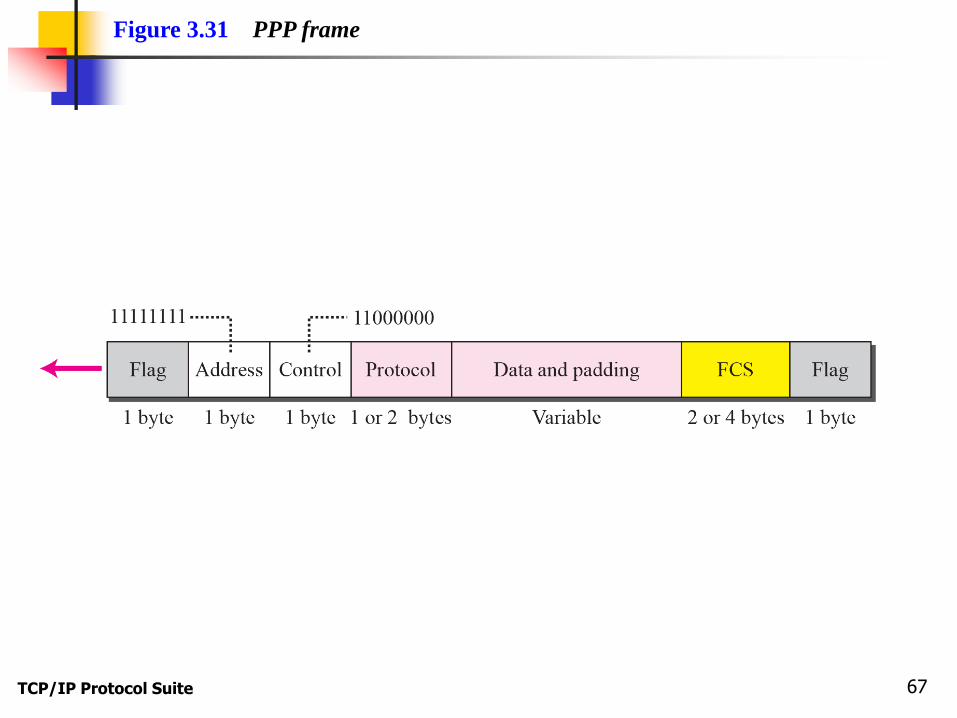
Point-to-Point Protocol (PPP)
Link Control Protocol (LCP)
Network Control Protocol (NCP)
PPP over Ethernet (PPPoE)
TCP/IP Protocol Suite 67
Figure 3.31 PPP frame
TCP/IP Protocol Suite 68
3-4 SWITCHED WANS
The backbone networks in the Internet can be
switched WANs. A switched WAN is a wide area
network that covers a large area (a state or a
country) and provides access at several points to the
users. Inside the network, there is a mesh of point-
to-point networks that connects switches. The
switches, multiple port connectors, allow the
connection of several inputs and outputs.
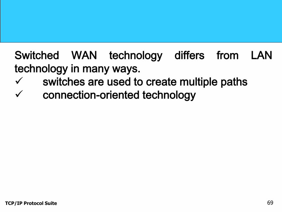
Switched WAN technology differs from LAN
technology in many ways.
TCP/IP Protocol Suite 69
Switched WAN technology differs from LAN
technology in many ways.
switches are used to create multiple paths
connection-oriented technology
TCP/IP Protocol Suite 70
Topics Discussed in the Section
X.25
Conflict with IP
Frame Relay
ATM: is a cell network

TCP/IP Protocol Suite 71
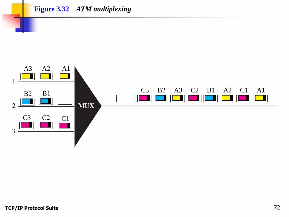
A cell network uses the cell as the basic
unit of data exchange.
A cell is defined as a small, fixed-size
block of information.
Note
TCP/IP Protocol Suite 72
Figure 3.32 ATM multiplexing
A1
C1
A2
B1
C2
B2
C3
A3
A1C1A2B2 B1C3 C2A3
TCP/IP Protocol Suite 73
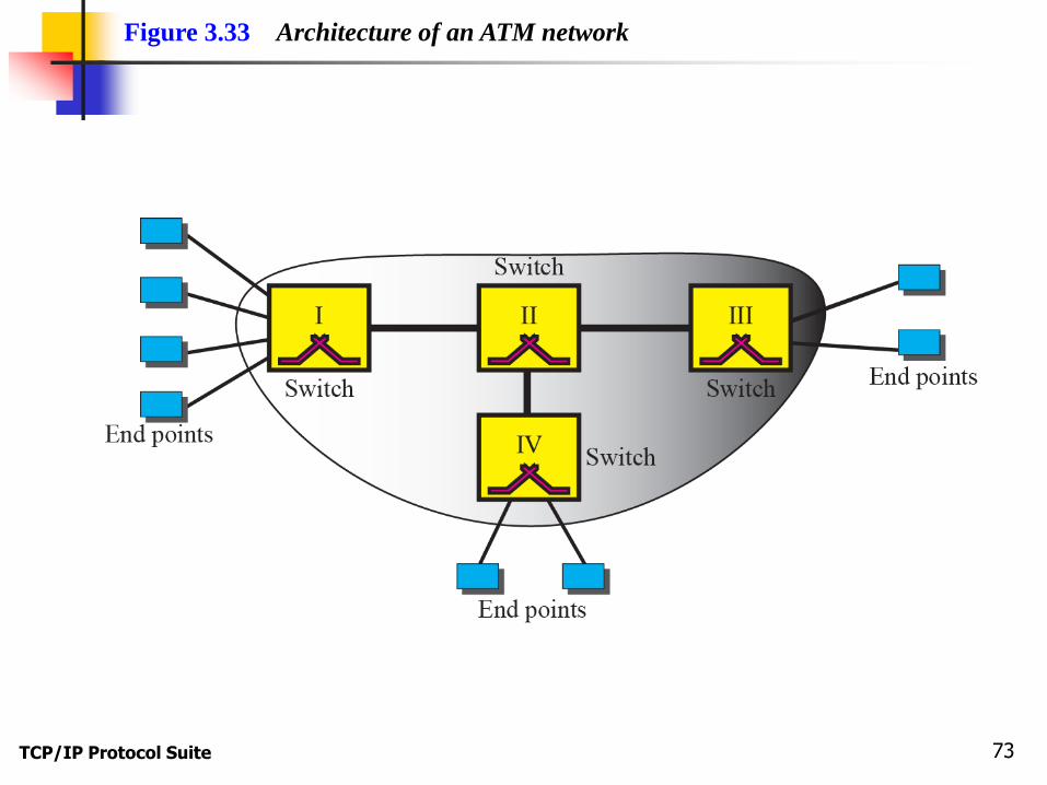
Figure 3.33 Architecture of an ATM network

TCP/IP Protocol Suite 74
Figure 3.34 Virtual circuit

TCP/IP Protocol Suite 75
A virtual connection is defined by a pair
of numbers: the VPI and the VCI.
Note

TCP/IP Protocol Suite 76
Figure 3.35 ATM layers
TCP/IP Protocol Suite 77
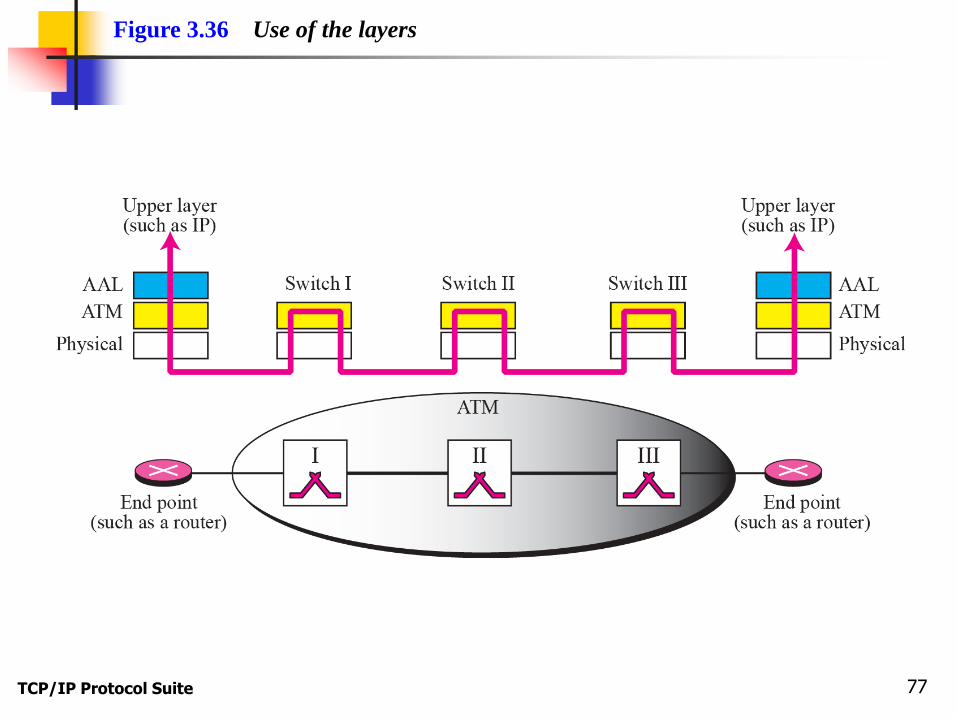
Figure 3.36 Use of the layers

TCP/IP Protocol Suite 78
The IP protocol uses the AAL5 sublayer.
Note

TCP/IP Protocol Suite 79
Figure 3.37 AAL5

TCP/IP Protocol Suite 80
Figure 3.38 ATM layer

TCP/IP Protocol Suite 81
Figure 3.39 An ATM cell

TCP/IP Protocol Suite 82
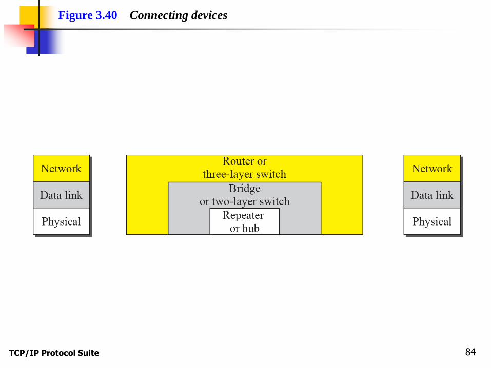
3-5 CONNECTING DEVICES
LANs or WANs do not normally operate in isolation.
They are connected to one another or to the
Internet. To connect LANs and WANs together we
use connecting devices. Connecting devices can
operate in different layers of the Internet model. We
discuss three kinds of connecting devices: repeaters
(or hubs), bridges (or two-layer switches), and
routers (or three-layer switches).

TCP/IP Protocol Suite 83
Topics Discussed in the Section
Repeaters (hubs)
Bridges (two-layer switches)
Routers (three-layer switches)
TCP/IP Protocol Suite 84
Figure 3.40 Connecting devices

TCP/IP Protocol Suite 85
Figure 3.41 Repeater or hub
Sent
Maintained
TCP/IP Protocol Suite 86
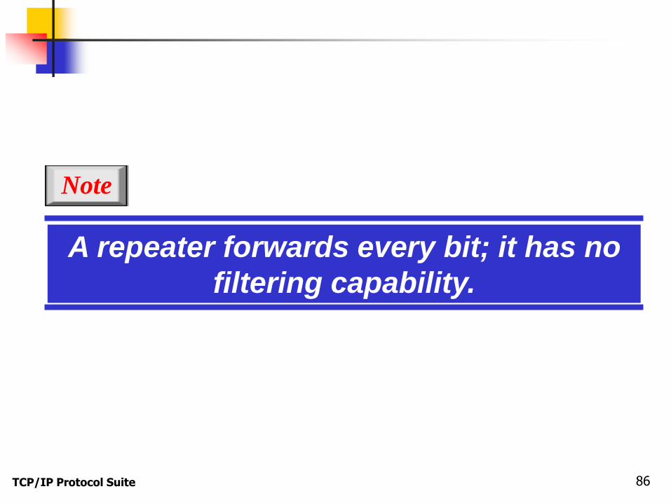
A repeater forwards every bit; it has no
filtering capability.
Note
TCP/IP Protocol Suite 87
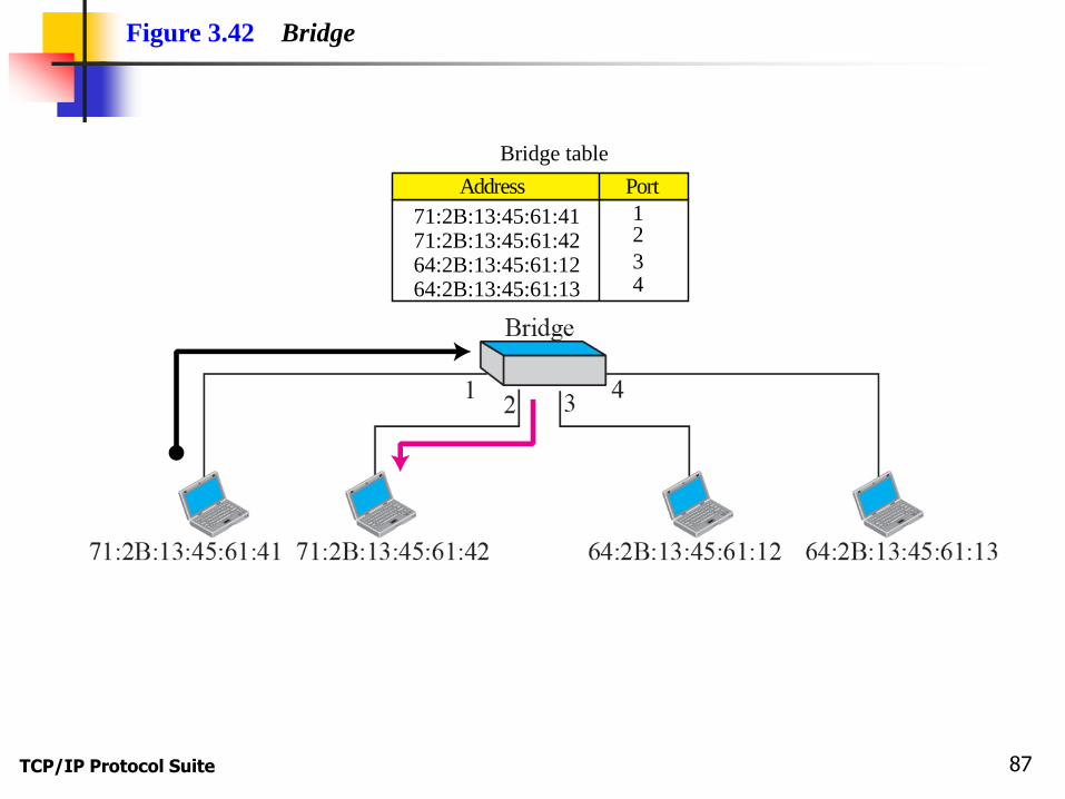
Figure 3.42 Bridge
71:2B:13:45:61:41 1
43
271:2B:13:45:61:4264:2B:13:45:61:1264:2B:13:45:61:13
Address Port
Bridge table
TCP/IP Protocol Suite 88
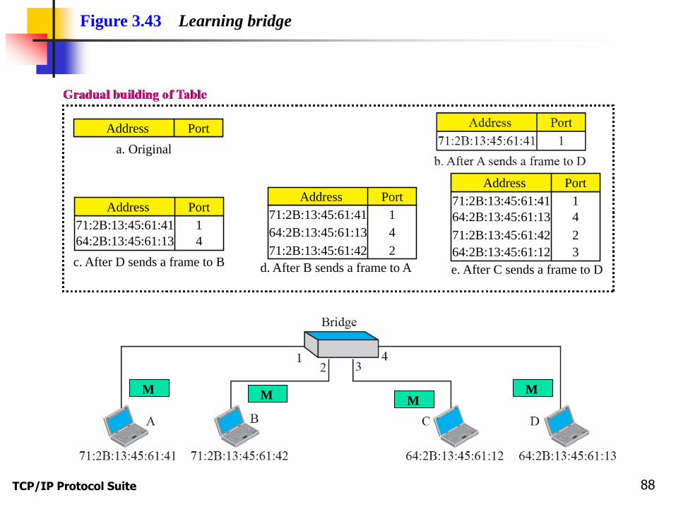
Figure 3.43 Learning bridge
a. Original
Address Port
c. After D sends a frame to B
71:2B:13:45:61:41 1
464:2B:13:45:61:13
Address Port
d. After B sends a frame to A
71:2B:13:45:61:41 1
4
271:2B:13:45:61:42
64:2B:13:45:61:13
Address Port
e. After C sends a frame to D
71:2B:13:45:61:41 1
4
3
271:2B:13:45:61:42
64:2B:13:45:61:12
64:2B:13:45:61:13
Address Port
M M M M

TCP/IP Protocol Suite 89
A bridge has a table used in filtering
decisions.
Note
A bridge does not change the physical
(MAC) addresses in a frame.

TCP/IP Protocol Suite 90
Topics Discussed in the Section
Routers (three-layer switches)
Can connect LANs and WANs together
Has a physical and logical (IP) address for each of
its interfaces
Act only on the destination
Change the physical address of the package (both
source and destination) when it forwards the packet

TCP/IP Protocol Suite 91
Figure 3.44 Routing example

TCP/IP Protocol Suite 92
A router is a three-layer (physical, data
link, and network) device.
Note
A router changes the physical
addresses in a packet.

TCP/IP Protocol Suite 93
A repeater or a bridge connects
segments of a LAN.
A router connects independent LANs or
WANs to create an internetwork
(internet).
Note
TCP/IP Protocol Suite 94
Summary:
To briefly discuss the technology of dominant wired LANs,
Ethernet, including traditional, fast, gigabit, and ten-gigabit
Ethernet.
To briefly discuss the technology of wireless WANs, including
IEEE 802.11 LANs, and Bluetooth.
To briefly discuss the technology of point-to-point WANs
including 56K modems, DSL, cable modem, T-lines, and SONET.
To briefly discuss the technology of switched WANs including
X.25, Frame Relay, and ATM.
To discuss the need and use of connecting devices such as
repeaters (hubs), bridges (two-layer switches), and routers
(three-layer switches).