chapter 34: geometric optics - erbion 34.pdf · chapter 34: geometric optics • it is all about...
TRANSCRIPT
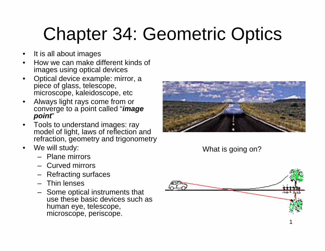
Chapter 34: Geometric Optics• It is all about images• How we can make different kinds of
images using optical devices• Optical device example: mirror a• Optical device example: mirror, a
piece of glass, telescope, microscope, kaleidoscope, etc
• Always light rays come from or converge to a point called “imageconverge to a point called image point”
• Tools to understand images: ray model of light, laws of reflection and refraction, geometry and trigonometry, g y g y
• We will study:– Plane mirrors– Curved mirrors
Refracting surfaces
What is going on?
– Refracting surfaces– Thin lenses– Some optical instruments that
use these basic devices such as h t lhuman eye, telescope, microscope, periscope.
1

Reflection and Refraction at a l S fplane Surface
• Vocabulary: y– Object: anything from which light rays radiate
• Self luminous• Non luminous• Non luminous
– Point object: a mathematical model for a dimensionless object(we will study).
– Extended object: an object with length, width, and height (composed of many point objects).
– Optical system: a system that admits the light rays fromOptical system: a system that admits the light rays from an object and generates an image of the said object.
– Optical axis: a mathematical line drawn to take advantage of the symmetry of the optical systemadvantage of the symmetry of the optical system.
2

Image formation by reflecting surfaces Pl iPlane mirrors
• The diverging rays from an object (P) hit the flat reflecting surface al mhit the flat reflecting surface
• They experience specular reflection• Reflected rays diverge as if they were
coming from a point on the other side of
Opt
ica
syst
em ImageObject
g pthe mirror (p’)
• Our eyes focus those rays onto the retina
• Retina sends many signals to the brain• Retina sends many signals to the brain from the right and left eye.
• The brain constructs not only an image but also depth and distance of the bj t Optical axisobject.
• Rays from diffused reflection do not add up to a clear image.
3

Image formation by refracting surfacesI f f i lInterface of two material
• The diverging rays from an object (P) hit the flat surface al mthe flat surface
• They experience refraction• Refracted rays diverge as if they were
coming from a different point on the
Opt
ica
syst
em ImageObject
g psame side of the surface (p’)
• Our eyes focus those rays on the retina • Retina sends many signals to the brain
from the right and left eyefrom the right and left eye. • The brain constructs not only an image
but also depth and distance of the object which may be different than the position f th l bj tof the real object.
• If the surface was not smooth rays from the object would be diffused and wouldnot add up to a clear image.p g
4

Types of ImageTypes of Image• Virtual image: if the rays g y
constructing an image do not actually pass through the image pointthe image point
• Real image: if the rays constructing an image actually pass through the image
• Identify which of these• Identify which of these images are virtual and which ones real?
5

Sign rules for image formationSign rules for image formation• Object distance: + when the object is on the
same side of the reflecting or refracting surfacesame side of the reflecting or refracting surface as the incoming light; else -
• Image distance: + when the image is on the g gsame side of the reflecting or refracting surface as the outgoing light; else –
• Radius of curvature of a spherical surface: +when the center of curvature is on the same
id th t i li ht lside as the outgoing light; else –• Real: + Virtual negative• Above optical axis: + Below optical axis: -
6

Image location by a plane mirrorImage location by a plane mirror• Image is produce by reflection
A l d d f al m• At least two rays are needed to form an image
– Identify the angles of reflection for each ray– Draw the reflected rays
Opt
ica
syst
em ImageObject
– Wherever they meet is the image point.• What if they did not intersect? Example: • Construct image of a candle at 2 meters• Construct image of a candle at 2 meters
from a flat mirror– parallel to the mirror surface.– Perpendicular to the mirror surface p
• Identify the object distance, the image distance and the relationship between the two
• Apply the sign convention• Apply the sign convention.
7

Image of an extended objectM ifi i f l iMagnification of a plane mirror
• To construct image of an gextended object we chop it to point objects and build the image point by g p ypoint.
• What is the ratio between the object and image sizethe object and image size for plane mirror?
• Lateral magnification:ratio of the image andratio of the image and object heights
• For plane mirror m=y’/y=-s’/s=?
8

More about imagesMore about images• Erect (upright): both image
and object arrows are parallel (y=y’)
• Inverted: image and object arrows are anti-parallel (x=-x’)p ( )
• PS and PQ are not inverted but PR is inverted
• Plane mirrors inverts back• Plane mirrors inverts back and front but they don’t invert up and down.Wh i h i f h l l• What is the sign of the lateral magnification in each case?
• What is the sign of the glongitudinal magnification in each case? 9

A image can act like an object to d d iproduce a secondary image
• P is a real object j• P’1 is a virtual image
formed by mirror 1• P’ acts like a virtual• P 1 acts like a virtual
object to form P’3 by mirror 2P i l bj t• P is a real object
• P’2 is a virtual image formed by mirror 2y
• P’2 acts like a virtual object to form P’3 by mirror 1mirror 1
10

Reflection at a spherical surfaceReflection at a spherical surface• We need magnification and real images. Plane mirrors can’t offer
any of these but spherical mirrors offer both. • Spherical mirror presentation• Spherical mirror presentation
– R radius of curvature– C center of curvature– V vertex (center of the mirror surface)V vertex (center of the mirror surface)– Optic axis: a line connecting C and V
• Use laws of reflection construct image of the point P.• Use the sign convention to determine signs of the s, s’, C, R.g g , , ,• What is type of the image?• What is a real image good for?
11

Paraxial imaging by spherical mirrorsParaxial imaging by spherical mirrors0The small angle approximation (SAA) or paraxial optics: viewing angle < 10
tan sin (in radians) or small and/or distant objects on the optical axisα α α
→
tan sin (in radians) or small and/or distant objects on the optical axis.
Paraxial image location formula by spherical
α α α
1 1 2 morrors :'s s R
+ =
Away from optic axis (non-paraxial optics), spherical mirrors show i.e image of a point is not exactly a point. The angles are exaggerated
aberrations
The angles are exaggerated for ease of presentation.
01R=57 0
0
.3 0.175R=10
12

Paraxial imaging by spherical mirrorsParaxial imaging by spherical mirrorsParaxial approximation:
& '& Rδ⎧ & '&
tan
s s Rhs
δ
α α
<<⎧⎪⎪⎪⎪
tan'
shs
β β
⎪⎪⎨⎪⎪
tan
2
hR
φ φ
β θ
⎪⎪⎪⎩
⎫22
β α θβ α φ
φ α θ= + ⎫
→ + =⎬= + ⎭
2 1 1 2' '
h h hs s R s s R+ = → + =
13

Spherical mirrors: focal point and focal length
• Focal point is position of the image of an object at infinity. • Focal distance is the distance from the focal point to the vertex of the mirror.
1 1 2Object at infinity: 's R
⎧ + =⎪ ∞⎪⎨ RImag: s'=
2
R
f
⎪⎨⎪ =⎪⎩⎧ RObject at focal point: s=
2Image : s'=
f⎧ =⎪⎨⎪ ∞⎩Image-object relation:
1 1 1s 's f+ =
s
.
f
Image and object points are conjugate points14

Spherical mirrors: focal point and focal length
• Focal point is position of the image of an object at infinity. • Focal distance is the distance from the focal point to the vertex of the mirror.
1 1 2Object at infinity: 's R
⎧ + =⎪ ∞⎪⎨ RImag: s'=
2
R
f⎨⎪ =⎪⎩⎧ RObject at focal point: s=
2Image : s'=
f⎧ =⎪⎨⎪ ∞⎩Image-object relation:
1 1 1s 's f+ =
15.
f
Image and object points are conjugate points

Image of an extended object S h i l iSpherical mirror
• Consider a finite size object PQ
• Construct image of both ends P’Q’ends P Q
• y is the object height• y’ is the image height• Prove m=y’/y =-s’/s• m>0 image upright• m<0 image inverted• m<0 image inverted• ImI>1 image magnified• ImI<1 image downsized
16

Paraxial images: convex mirrorsI bj l i b h i l iImage-object relation by in paraxial approximation:
& '&s s Rδ <<⎧⎪
spherical convex mirrors
tan
tan
hsh
α α
β β
⎪⎪⎪⎪⎨⎪tan
'
tan
shR
β β
φ φ
⎪⎪⎪⎪⎩
22
2 1 1 2h h h
β α θβ α φ
β φ θ= + ⎫
→ + =⎬= + ⎭
2 1 1 2' '
' '
h h hs s R s s R
y sm
+ = → + =
= = −
Everything is the same as
y s
convex case if we follow the sing conventions properly. 17

Focal point of a convex mirrorFocal point of a convex mirrorFollow the sing conventions properly 1 1 2+
'0
' 0
s s Rs
+ =
>' 0
0Why?
sR<<
Why?1 1 2
's R+ =
∞ − −
'2Rf s= =
18
1 1 2 1's s R f
+ = =

Graphical ray tracing: i i b iconstructing images by mirrors
Four principal rays’ are traced using the laws of reflection1. Incoming ray parallel to the optical axis outgoing ray passes through F 2. Outgoing ray parallel to the optical axis incoming ray passes through F
3 A ray to the vertex reflects at the same angle on the other side of OX3. A ray to the vertex reflects at the same angle on the other side of OX4. A ray aiming the center of curvature reflects back at itself
19

Concave mirrors
a) Object outside center b) Object at the centerc) Object at the focal pointd) Object between the focal point and vertexd) Object between the focal point and vertexe) Where is the image if object is between the center and focal point?f) Explain the image properties for the convex mirror? 20
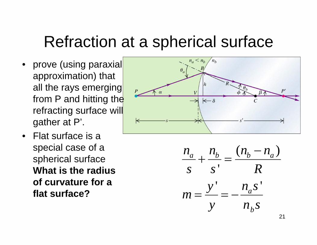
Refraction at a spherical surfaceRefraction at a spherical surface • prove (using paraxial
approximation) thatapproximation) that all the rays emerging from P and hitting the
f ti f illrefracting surface will gather at P’.
• Flat surface is aFlat surface is a special case of a spherical surface What is the radius
( )'
a b b an n n ns s R
−+ =
What is the radius of curvature for a flat surface?
'' a
s s Rn sym = = −
by n s21

Lateral magnification of a refracting h i l fspherical surface
• Obtain a formula for lateral magnification of a spherical refracting surface
• Discuss each formula for the case of plane refracting surface
'' a
b
n symy n s
= = −refracting surface by
22

Image formation by refraction• Calculate the image distance and magnification. (s’=+11.3 cm
m=-0.929)• What if the rod is immersed in water (n=1.33)? (s’=-21.3 cm
m=+2.33) • Suggest an easy experiment to see a real image in a tube with
spherical head.
23

Apparent depth in a swimming poolApparent depth in a swimming pool
• Calculate theCalculate the apparent depth of a 2.00 m deep swimming pool. (1.50 m or s’=-1.50 m)
• What is the nature of the image of the pool floor we see?floor we see?
24

Properties of thin lensesProperties of thin lenses– A lens is combination of two refracting surfaces– Thin lens: radii of curvature >> lens thickness
Si l h i l– Sign rules are the same as single refracting/reflecting surface
– The line that connects two centers of curvature is the optic axisp
– There are two focal points on equal distance from the thin lens (center)
– F1 is the object focal point (positive and real) F i th i f l i t ( iti d l)– F2 is the image focal point (positive and real)
– Focal lengths are the distances from the foci to the center of the lens
– There are two general category of lenses:There are two general category of lenses: • Converging lens or positive lens (similar to
the concave mirror)• Diverging lens or negative lens (similar to
th i )the convex mirror)
25

Constructing image of an extended bj i h i lobject with a converging lens
C t t i f• Construct image of an arrow (PQ) located on the optical axis of a thin converging lens with focal points at F1 and F2.
• Derive the object image• Derive the object-image and lateral magnification relations for thin lens. 1 1 1 's
• Discuss the image properties
1 1 1 '
sms s f s+ = = −
26

Converging lens image analysisConverging lens image analysis
• RealReal • Inverted about the optic axis or
rotated 1800 about the optic axis.p• No change in right handed or left
handedness of the imageg
27

Diverging lens or negative lensDiverging lens or negative lens• There are two focal points on equal
distance from the thin lens (center) ( )• F1 is the object focal point• F2 s the image focal point• Pay attention to the location of the
object and image focal points.• Negative focal lengths• Negative focal lengths• Virtual focal points• Same equations applySame equations apply
1 1 1 ' '
sms s f s+ = = −
s s f s28

Recognition of converging and di i ldiverging lens
• Edges thicker thanEdges thicker than center: diverging
• Center thicker than edges: Converging
29
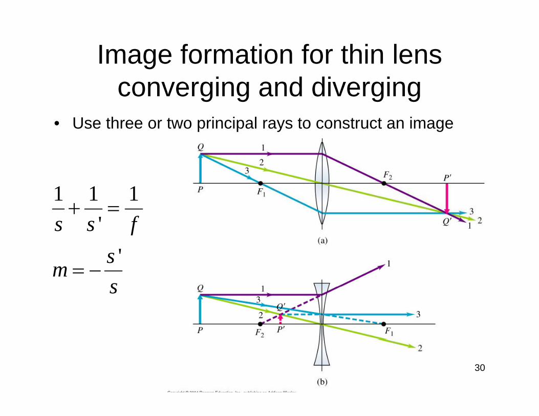
Image formation for thin lens i d di iconverging and diverging
• Use three or two principal rays to construct an imagep p y g
1 1 1's s f
+ =
'f
sms
= −s
30
Example:I f di i lImages for diverging lens
1. Imagine an object is approaching from infinity1. Imagine an object is approaching from infinity towards a diverging lens with focal length of 20.0 cm. How the image moves? Is it real or virtual? Get the image distances for s=100 0 cm s=40 0Get the image distances for s 100.0 cm, s 40.0 s=20.0 cm, s=10.0 cm, s=1.0 cm, s=0.001 cm.
2. How the magnification changes in each case?3. Draw a diagram for location of the object and
image when the object is at 40.cm 4 Answer the same questions for the case of4. Answer the same questions for the case of
converging lens with the same focal length.
31

Answer to the part 3 of the QuizAnswer to the part 3 of the Quiz
32

A lens and its radii of curvature R & RR1 & R2
• A lens has two spherical refracting surfaces.• The first surface with radius of curvature R1 that incoming rays hit is• The first surface with radius of curvature R1 that incoming rays hit is
called surface 1.• The second surface with radius of curvature R2 that incoming rays hit
is called surface 2is called surface 2.
33

Lensmaker’s equation for thin lens in paraxial approximation (small angles)paraxial approximation (small angles)A lens is combination of two spherical refracting surfaces. '
1 1 1
; a b b an n n ns s R
−+ =
Use the spherical refracting surface equation twice and the following facts to derive the
'2 2 1
b c c bn n n ns s R
−+ =
o o g acts to de e t elensmker’s equation. Paraxial approximation is used.
'2 11; ;
1 1 1( 1)
a c bn n n n s s
n
= = = = −
⎛ ⎞= − −⎜ ⎟
1 2
( 1)nf R R⎜ ⎟
⎝ ⎠
34

Images for converging lensImages for converging lens1. Imagine an object is approaching from infinity to g j pp g y
the F1 (the object focal point) of a converging lens. How the image moves? Is it real or virtual?
2 How image moves when the object moves from2. How image moves when the object moves from F1 towards the lens? Is image real or virtual?
3. What is the relative direction of motion of the bj t d i f th i l ?object and image for the converging lenses?
35

Images for converging lens
36

Optical instrumentsOptical instruments
• Single lens systemsSingle lens systems– Cameras– Eyeglasses y g– Magnifiers
• Two-lens or compound systems composed of a primary or objective lens forms a real image that is used by a secondary lens or eyepiece
l t k ifi d i t l ior ocular to make a magnified virtual image– Microscope
Telescope– Telescope37

Camera an optical instrument or an optical devicean optical instrument or an optical device• A real image of an object is recorded on a film (in
old cameras) or electronically (array of detectors ) y ( yin digital cameras)
• Net effect of the combined lens system is a i lconverging lens
“Camera” or a “light tight” box
38

Camera parts
A complicated lens andFilm or imager position fixed
object
A complicated lens and aperture system is used for correcting various b ti hobject aberrations such as
wavelength dependence of the refractive index
Image
Aperture control or diaphragm
(chromatic), astigmatism, coma, etc. allowing only light enter at angles it is
Shutter
light enter at angles it is designed for. The lens is moved
back and forth for focusing
39
g

Camera parts: ExerciseFilm or imager position fixed
objectImage
Aperture control or diaphragm
Shutteror diaphragm
When a camera is focused for an object the real image is exactly on the recording materialexactly on the recording material.Exercise: Assume the lens is focused for an object at a given distance. When we want to take picture of an object, t l di t d th l f that a larger distance do we move the lens away from the
recording material or bring it closer? 40

Camera angle of view & field of view for a given lens film combinationfor a given lens-film combination
• Field of view is defined as the largest angle of view l th di l di ialong the diagonal dimension
• Example: Compare angle of view of two lenses with f1=28mm and f2=300mm with a 24X35mm film for a di t f 10 ( 750 80)distance of 10m. (α1=750 α2=80)
α1 α2 ObjectImage
Camera Short focal length lensLarge angle of viewL ifi ti
Long focal length lensSmall angle of view Hi h ifi tiLow magnification
s’/s is smallHigh magnifications’/s is large 41

Exposure• Exposure: total light energy perExposure: total light energy per
unit area reaching the film (intensity)
• Proper image brightness require• Proper image brightness require certain limit of exposure
• Exposure is controlled by:p y– Shutter time (usually 1 s to
1/1000 s)lens aperture diameter (D)– lens aperture diameter (D) larger lenses provide more exposure and brighter
i tpictures.• Digital cameras control the
exposure automatically dueexposure automatically due to sensitivity of their pixels
42

Aperture; ; Exposure #fExposure: amount of admitted light into the camera. Exposure is controlled by two elements:
li h i id h i llight power incident at the image plane1) Irradiance: area of the film or CCD or CMOS imager
2) Shutter spe
eE =
ed: 1/ (automatic in digital cameras)t2) Shutter spe hutter22
2
ed: 1/ (automatic in digital cameras)
area of apertureelative aperture of a lensarea of image
s
e
t
D DE rd f
⎛ ⎞∝ ∝ = ∝ ⎜ ⎟
⎝ ⎠area of imageImage size is proportional to the focal length of the lens
d fd f
f
α⎝ ⎠
#
1
ffD
E
=
43
2( #)eEf
∝
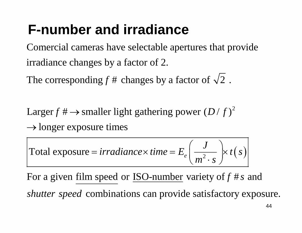
F-number and irradianceComercial cameras have selectable apertures that provide irradiance changes by a factor of 2.
The corresponding # changes by a factor of 2 .f
2Larger # smaller light gathering power ( / )longer expos
f D f→→ ure timesg p
( )2Total exposure eJirradiance time E t s
m s⎛ ⎞= × = ×⎜ ⎟⋅⎝ ⎠
For a given film speed or ISO-number variety of # and
bi i id i f
m s
f s
h d
⋅⎝ ⎠
44
combinations can provide satisfactory exposure. shutter speed

F-number and irradianceExample :
1
We want to make two images with different shutter speeds.For case 1: # 8 the shutter speed is (1/50)s. f =Find the equivalent / for shutter speed (1/100)s that provides the same exposure.
f stop
( )2 2
1 1 1Total exposure for case1 1 28t s⎛ ⎞ ⎛ ⎞= = =⎜ ⎟ ⎜ ⎟
Solution :
( )1
2 2
Total exposure for case1 1.28# 8 50
1 1 1 1 1Total exposure for case2 1 28
t sf⎜ ⎟ ⎜ ⎟
⎝ ⎠⎝ ⎠
⎛ ⎞ ⎛ ⎞= = =⎜ ⎟ ⎜ ⎟
2 2
2 2
Total exposure for case2 1.28# 100 # 2 50
1 1 1 1 12 2 1 4 # 5 6
f f
f
= = =⎜ ⎟ ⎜ ⎟⎝ ⎠ ⎝ ⎠
⎛ ⎞ ⎛ ⎞ ⎛ ⎞⎜ ⎟ ⎜ ⎟ ⎜ ⎟
45
22 1 2 1
2 2 1.4 # 5.6# # # # 8
ff f f f
⎛ ⎞= → = = → =⎜ ⎟ ⎜ ⎟ ⎜ ⎟⎝ ⎠⎝ ⎠ ⎝ ⎠

Aperture size decreases
Irradiance decreasesdecreases
46

ExamplesExamples• The light intensity reaching a film is inversely proportional g y g y p p
to the square of the f-number and exposure time.• Which lens has more light gathering capacity?
a) f=50 mm, D=25 mm (D/f)a) f 50 mm, D 25 mm (D/f)b) f=50 mm, D=50 mmc) f=100 mm, D=50 mmd) f=100 mm, D=100 mm
• What is the effective diameters of the f/2, f/2.8, f/4, f/5.6, f/8, f/11, f/16 apertures (f-stops with factor of 2 decrease in intensity)? (2f, 2.8f, …)in intensity)? (2f, 2.8f, …)
• Compare these two exposures.– D=f/4 and 1/500 s
D=f/8 and 1/125 s– D=f/8 and 1/125 s
47
The eyeThe eye• The eye (camera) is an optical machine
with variable focal length that can produce a real image of the outside objects at
Aqueous humorn=1.3
a real image of the outside objects at various distances on a sensitive screen retina (film or imager).
• Change of the effective focal length of the
ciliary muscle
Lretinag g
eye is called accommodation and it depends on the age and how well the ciliary muscle can change the curvature of the crystalline lens
Lens
Optic of the crystalline lens.
• Far point: the furthest point that eye can see. Infinity for a healthy eye
• Near point: the closest point that eye can 1 1 1
nerve
• Near point: the closest point that eye can construct a clear image of it (~25 cm for a healthy eye)
• What is the lens type of our eyes?
1 1 1's s f
+ =yp y
• What are the image properties?48
f

Data related to the eyeData related to the eye
49http://hyperphysics.phy-astr.gsu.edu/hbase/vision/eyescal.html

Problematic eyesProblematic eyes• Myopic or near sighted eye has a shorter
far point than a healthy eye, as a result it p y y ,can’t see the far objects clearly– it has a lens with shorter focal length– Image of far objects fall in a short distanceImage of far objects fall in a short distance
than retina• Hyperopic or far sighted eye has a longer
near point than a healthy eye as a result itnear point than a healthy eye, as a result it can’t see the close objects clearly.– It has a lens with longer focal length
Image of the near objects fall behind the– Image of the near objects fall behind the retina
• Presbyopic eye has lost the accommodation power due to aging near point moves from 10power due to aging near point moves from 10 cm at age 10 to about 200 cm at 60
50

Correcting a hyperopic & presbyopic) N i h d f heye Near point has moved further
51

Correcting a mypoic eyeFar point has moved closer
52

AstigmatismAstigmatism
• Surface of the corneaSurface of the cornea is not spherical. It can be for example cylindrical.
• Image of the horizontal and vertical lines are not on the same planesame plane.
53
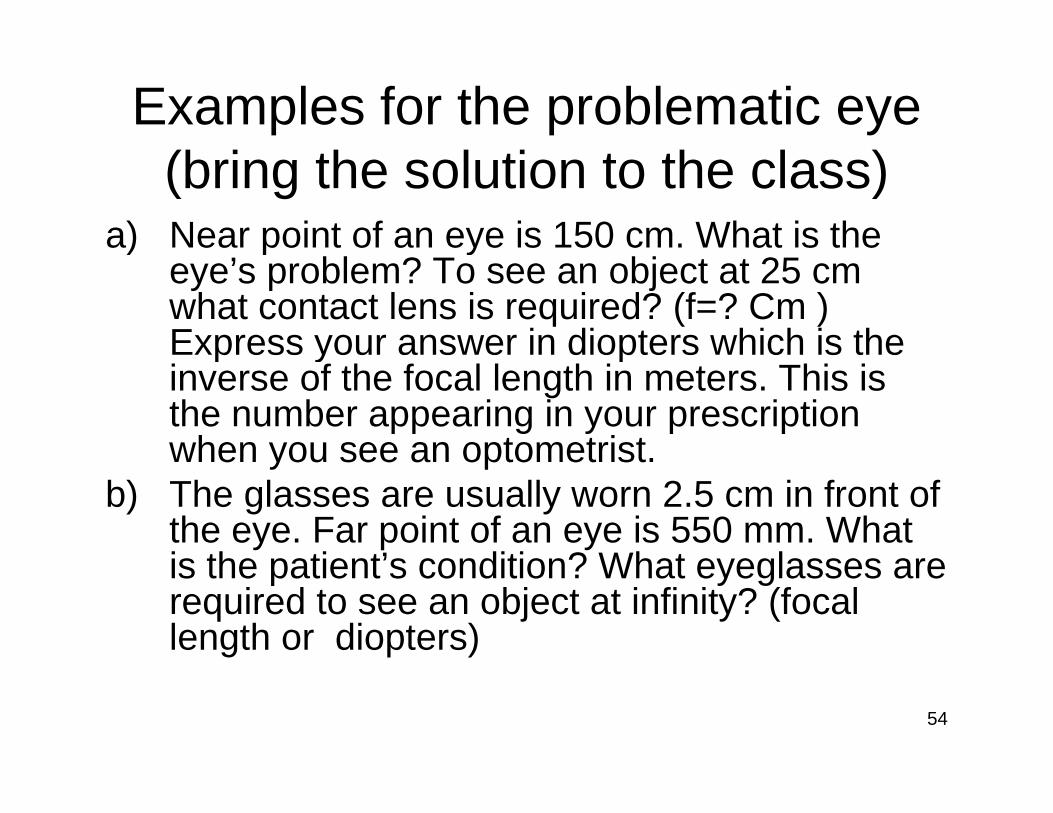
Examples for the problematic eye (b i h l i h l )(bring the solution to the class)
a) Near point of an eye is 150 cm. What is the ) p yeye’s problem? To see an object at 25 cm what contact lens is required? (f=? Cm ) Express your answer in diopters which is the p y pinverse of the focal length in meters. This is the number appearing in your prescription when you see an optometristwhen you see an optometrist.
b) The glasses are usually worn 2.5 cm in front of the eye. Far point of an eye is 550 mm. What is the patient’s condition? What eyeglasses areis the patient s condition? What eyeglasses are required to see an object at infinity? (focal length or diopters)
54

Example: An image as an object (b i h l i h l )(bring the solution to the class)
• A two lens system: an object with 8.0 cmA two lens system: an object with 8.0 cm height is placed at 12.0 cm to the left of a converging lens with a focal length of 8.0 cm.converging lens with a focal length of 8.0 cm. A second converging lens with focal length of 6.0 cm is placed at 15.0 cm to the right of the 6 0 c s p aced at 5 0 c to t e g t o t efirst lens. Both lenses have the same optic axis. Find the image position, size, and a s d e age pos o , s e, a dorientation for the two lens system.
• Make the second lens diverging and solveMake the second lens diverging and solve the problem 55

Two lens systemTwo lens system
L LL1 L2
56

Apparent and angular size• Apparent size: depends on the size of object’s image on
the retina Angular size: is the angle subtended by the object• Angular size: is the angle subtended by the object
• When an object is closer to the eye, its angular size is bigger so is the apparent size. But what happens to objects closer than near point of the eye?
57
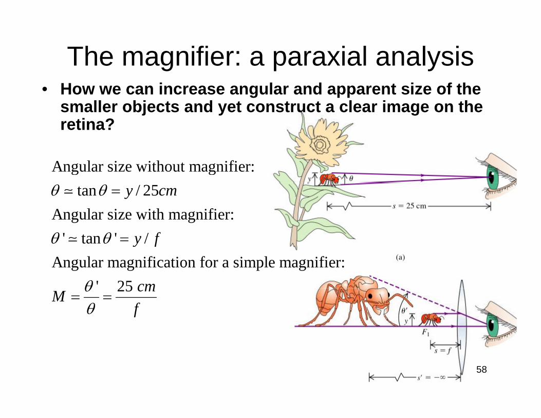
The magnifier: a paraxial analysis• How we can increase angular and apparent size of the
smaller objects and yet construct a clear image on the retina?
Angular size without magnifier: tan / 25
Angular size with magnifier: ' t ' /
y cm
f
θ θ
θ θ
=
' tan ' /Angular magnification for a simple magnifier:
' 25
y f
cm
θ θ
θ
=
25 cmMf
θθ
= =
58

The magnifier: ExampleLimit on the angular magnification is aberration, usuall 4 for simple lenses and 20 for the corrected lenses
××simple lenses and 20 for the corrected lenses.
Difference between the lateral, m, and angular, M, magnification. For image at infinity t
×
he lateral magnification is meaninglessFor image at infinity the lateral magnification is meaningless.
A 2mm insect is being observed by a 4 magnifier in a comfortable setting for the eye
×Example : in a comfortable setting for the eye. a) What is the focal length of the mgnifier? b) What is the angular size of the insect's image?b) What is the angular size of the insect s image? c) What is the lateral magnification?
59

Microscope• Offers a much greater
magnification than a simplemagnification than a simple magnifier.
• Two converging or positive lenses • Object placed just beyond the first
lens’s focal point makes a real inverted imageinverted image
• This image is just inside the object focal point of the second lens creating a virtual, upright, and magnified image
60

Microscope• Two converging or positive lenses • Object placed just beyond the first
l ’ f l i t k llens’s focal point makes a real inverted image
• This image is just inside the object Or cularThis image is just inside the object focal point of the second lens creating a virtual, upright, and magnified imagemagnified image
• For relaxed viewing the image from the primary is set on the focal point p y pof the secondary lens.
• This creates the final image at infinityinfinity.
61

The microscope: a paraxial analysis
1 2'
Overall angular magnification of a compound microscope: lateral mag. of objective angular mag. of ocularM m M= × = ×
'1
1 1 11
- is the lateral magnification of the objective (usually )
' 25
sm s fs
cmθ
=
22
2 2
' 25 cmMf
θθ
= = is the angular magnification of the ocular (like the
magnifielr case)' '1 1
1 21 2 1 2
magnifielr case)
(25 )25So | | | s cm scmM m Mf f f f
⎛ ⎞⎛ ⎞ ⎛ ⎞= × = − =⎜ ⎟⎜ ⎟ ⎜ ⎟
⎝ ⎠⎝ ⎠ ⎝ ⎠1 2 1 2
and virtual. The shorter the focal lengths of
th
f f f f⎝ ⎠⎝ ⎠ ⎝ ⎠Final image is inverted
e objective and ocular, the higher the magnification.j , g g
62
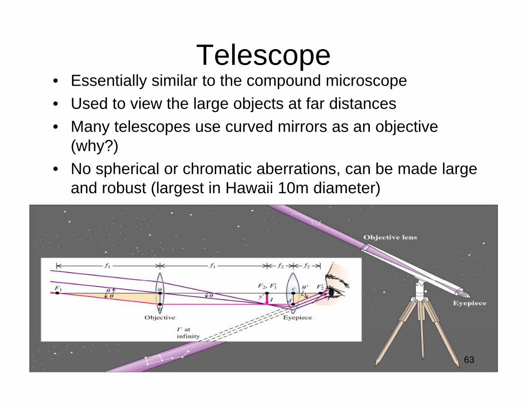
TelescopeE ti ll i il t th d i• Essentially similar to the compound microscope
• Used to view the large objects at far distances • Many telescopes use curved mirrors as an objective• Many telescopes use curved mirrors as an objective
(why?)• No spherical or chromatic aberrations, can be made large
and robust (largest in Hawaii 10m diameter)
63

The telescope: a paraxial analysis
1 2
Telescope length for most comfortable viewing situation L (image at infinity)A l ifi ti f t l ( i b th bj t d i
f f= +Angular magnification of a telescope (since bothe object and image
' 'are at : ( since image is yMf
θ θθ
−∞ = = − inverted)
1fθ
'
2
' ( image is not inverted by this lens) yf
θ = +2
2 1
1 2
' ' ( final image is inverted). '
ff fyM
f y fθθ
−= = = − −
Why we can't use a telescope as a microscope or vise versa?The longer the objective focal length the higher the magnification
The shorter the eyepiece focal length the higher the magnification64

Example: reflecting telescopeExample: reflecting telescope
• Radius of curvature for a reflectingRadius of curvature for a reflecting telescope objective is 1.30 m. Focal length of the eyepiece is 1.10 cm. The final image is at infinity.a) What should be the distance between
th i l d th t fthe eyepiece lens and the vertex of the mirror? (66.10cm)
b) What is the angular magnification? b) a s e a gu a ag ca o(-59.1)
65

Example: Cassegrain telescopeExample: Cassegrain telescope• Focal length of the primary:
2 5 m2.5 m• Focal length of the
d 1 5secondary: -1.5• Distance from the vertex of
the primary to the detector: 15 cm
• What should be the distance of vertexes of two mirrors?
66

67

68

69

70

71

72
73

74

75

76