chapter 35 &36 physical optics - austin community college
TRANSCRIPT

Chapter 35 &36
Physical Optics
MFMcGraw-PHY 2426 Chap35 & 36a-Physical Optics - Revised 7/13/2013 2
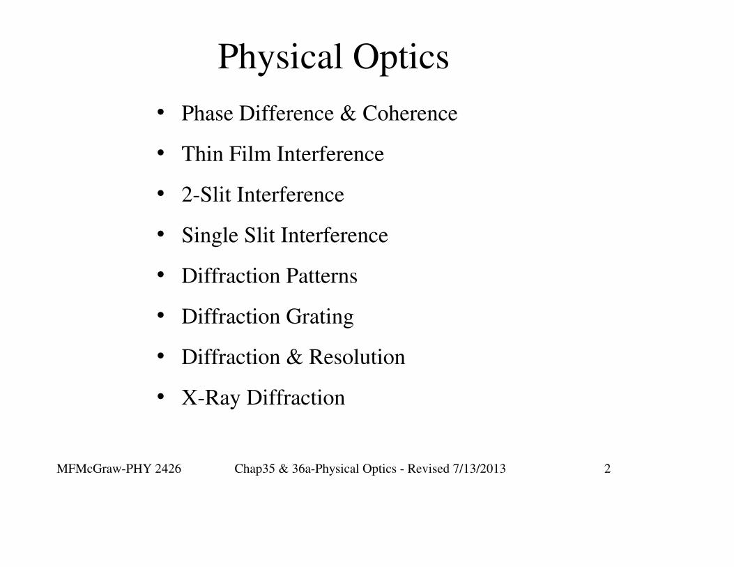
Physical Optics
• Phase Difference & Coherence
• Thin Film Interference
• 2-Slit Interference
• Single Slit Interference
• Diffraction Patterns
• Diffraction Grating
• Diffraction & Resolution
• X-Ray Diffraction

MFMcGraw-PHY 2426 Chap35 & 36a-Physical Optics - Revised 7/13/2013 3
Periodic Waves
A periodic wave repeats the same pattern over and over.
• For periodic waves: v = λf
• v is the wave’s speed
• f is the wave’s frequency
• λ is the wave’s wavelength
The period T is measured by the amount of time it takes
for a point on the wave to go through one complete cycle
of oscillations. The frequency is then f = 1/T.

MFMcGraw-PHY 2426 Chap35 & 36a-Physical Optics - Revised 7/13/2013 4
The maximum
displacement
from equilibrium
is amplitude (A)
of a wave.
One way to determine the wavelength is by measuring
the distance between two consecutive crests.
Periodic Waves

MFMcGraw-PHY 2426 Chap35 & 36a-Physical Optics - Revised 7/13/2013 5
When two waves travel
different distances to reach
the same point, the phase
difference is determined
by:
πλ 2
difference phase21 =− dd
Note: This is a ratio comparison. λ is not equal to 2π
Phase Difference

MFMcGraw-PHY 2426 Chap35 & 36a-Physical Optics - Revised 7/13/2013 6
The Principle of Superposition
For small amplitudes, waves will pass through each
other and emerge unchanged.
Superposition Principle: When two or more
waves overlap, the net disturbance at any point is
the sum of the individual disturbances due to each
wave.

MFMcGraw-PHY 2426 Chap35 & 36a-Physical Optics - Revised 7/13/2013 7
Two traveling wave
pulses: left pulse
travels right; right
pulse travels left.

MFMcGraw-PHY 2426 Chap35 & 36a-Physical Optics - Revised 7/13/2013 8
Interference
Two waves are considered coherent if they have the
same frequency and maintain a fixed phase relationship.
Two waves are considered incoherent if the phase
relationship between them varies randomly.
Two coherent
waves. The black
wave is π/4 radians
behind the orange
wave.x

MFMcGraw-PHY 2426 Chap35 & 36a-Physical Optics - Revised 7/13/2013 9
When waves are in phase, their superposition
gives constructive interference.
When waves are one-half a cycle out of
phase, their superposition gives destructive
interference.
This is referred to as:
“exactly out of phase” or “180o out of phase.”

MFMcGraw-PHY 2426 Chap35 & 36a-Physical Optics - Revised 7/13/2013 10
Constructive Interference
(Slinky Example)

MFMcGraw-PHY 2426 Chap35 & 36a-Physical Optics - Revised 7/13/2013 11
Destructive Interference
(Slinky Example)

MFMcGraw-PHY 2426 Chap35 & 36a-Physical Optics - Revised 7/13/2013 12
Constructive Interference. Means that the waves
ADD together and their amplitudes are in the same
direction
Destructive Interference. Means that the waves
ADD together and their amplitudes are in the
opposite directions.
Interference = Bad choice of words
• The two waves do not interfere with each other.
• They do not interact with each other.
• No energy or momentum is exchanged.

MFMcGraw-PHY 2426 Chap35 & 36a-Physical Optics - Revised 7/13/2013 13
Special Conditions for a Steady Optical
Interference Pattern
• Same wavelength and frequency
• Phase difference independent of time
• Amplitudes approximately equal
• Same polarization
These conditions are most easily achieved by deriving
the interfering light from the same source.

MFMcGraw-PHY 2426 Chap35 & 36a-Physical Optics - Revised 7/13/2013 14
Interference Patterns
Light from different sources can never yield a stationary
interference pattern
Different sources are inherently incoherent
Successful observation of a stationary interference
pattern.
∆ Optical Path length is small ~ a few wavelengths

MFMcGraw-PHY 2426 Chap35 & 36a-Physical Optics - Revised 7/13/2013 15
Reflection and Refraction
At an abrupt boundary between two media, a
reflection will occur. A portion of the incident
wave will be reflected backward from the boundary.
A portion of the incident wave will be transmitted
through the media. This is the refracted ray.

MFMcGraw-PHY 2426 Chap35 & 36a-Physical Optics - Revised 7/13/2013 16
When a wave is incident
on the boundary between
two different media, a
portion of the wave is
reflected, and a portion
will be transmitted into the
second medium. Reflected
ray is 180o out of phase
with respect to the incident
wave.
Reflection and Refraction

MFMcGraw-PHY 2426 Chap35 & 36a-Physical Optics - Revised 7/13/2013 17
The frequency of the transmitted wave remains the
same. However, both the wave’s speed and wavelength
are changed such that:
2
2
1
1
λλ
vvf ==
The transmitted wave will also suffer a change
in propagation direction (refraction). Described
by Snell's Law.
The Frequency is Constant

MFMcGraw-PHY 2426 Chap35 & 36a-Physical Optics - Revised 7/13/2013 18
When you have a wave that
travels from a “low density”
medium to a “high density”
medium, the reflected wave
pulse will be inverted. (180o
phase shift.)
The frequency of the reflected
wave remains the same.
The Reflected Wave & Phase Change

MFMcGraw-PHY 2426 Chap35 & 36a-Physical Optics - Revised 7/13/2013 19
Interference Due to Phase Differences
Phase Differences Result from
• Optical Path Differences
• Phase Shifting
∆(Phase) = ∆(Optical Path Length)+ ∆(Phase Shift)
The optical path length in a material of index of
refraction n is: d' = d n
Constructive Interference: ∆(Phase) = nλ; n = 0, 1, 2,...
Destructive Interference: ∆(Phase) = mλ/2; m = 1, 3, 5,...

MFMcGraw-PHY 2426 Chap35 & 36a-Physical Optics - Revised 7/13/2013 20
Ray 1 is phase shifted by λ/2
at the air-film interface
Ray 2 is not phase shifted at
the film-air interface
Phase Shifting Upon Reflection
Extra Conditions:
• Monochromatic light
• Nearly normal incidence

MFMcGraw-PHY 2426 Chap35 & 36a-Physical Optics - Revised 7/13/2013 21
Ray 1 is phase shifted by λ/2
at the air-film interface
Ray 2 is not phase shifted at
the film-air interface
Constructive Interference
The difference in the optical path
length is the distance the 2nd ray
travels in the soap film.
The film distance is 2t.
The optical path length is 2t/nsoap
Looking for constructive interference.
This requires that the phase difference of 1
and 2 are an integral number of
wavelengths.
Monochromatic light

MFMcGraw-PHY 2426 Chap35 & 36a-Physical Optics - Revised 7/13/2013 22
Constructive Interference
The film distance is 2t. The optical path
length difference λ’/2 = 2t
Constructive interference requires that the phase difference of 1 and 2 be
equal to an integral number of wavelengths.
Monochromatic light
∆(Phase) = ∆(Optical Path Length)+ ∆(Phase Shift)
Constructive interference requires a minimum phase difference equivalent to
one wavelength = λ
Phase shifting contributes λ/2 to the total phase
difference. The optical path length difference needs
to contribute another λ/2.
⇒soap soap
λ λ= 2t t =
2n 4n

MFMcGraw-PHY 2426 Chap35 & 36a-Physical Optics - Revised 7/13/2013 23
Destructive Interference
The film distance is 2t. The optical path
length difference λ’ = 2t
Destructive interference requires that the phase difference of 1 and 2 be
equal to an odd multiple of half wavelengths.
Monochromatic light
∆(Phase) = ∆(Optical Path Length)+ ∆(Phase Shift)
Denstructive interference requires a minimum phase difference equivalent to
one-half wavelength = λ/2
Phase shifting contributes λ/2 to the total phase
difference. The optical path length difference needs
to contribute λ.
⇒soap soap
λ λ= 2t t =
n 2n

MFMcGraw-PHY 2426 Chap35 & 36a-Physical Optics - Revised 7/13/2013 24
Ray 1 is phase shifted by λ/2
at the air-film interface
Ray 2 is also phase
shifted by λ/2 at the film-
glass interface
Destructive Interference
∆(Phase) = ∆(Optical Path Length)+ ∆(Phase Shift)

MFMcGraw-PHY 2426 Chap35 & 36a-Physical Optics - Revised 7/13/2013 25
Destructive Interference
∆(Phase) = ∆(Optical Path Length)+ ∆(Phase Shift)
Destructive interference requires that the phase difference of 1 and 2 be
equal to a half-integral number of wavelengths.
Destructive interference requires a minimum phase difference equivalent to
one wavelength = λ/2
Phase shifting contributes 0 to the total
phase difference. The optical path length
difference needs to contribute the λ/2.
The film distance is 2t. The optical path
length difference λ’/2 = 2t
⇒film film
λ λ= 2t t =
2n 4n
MFMcGraw-PHY 2426 Chap35 & 36a-Physical Optics - Revised 7/13/2013 26
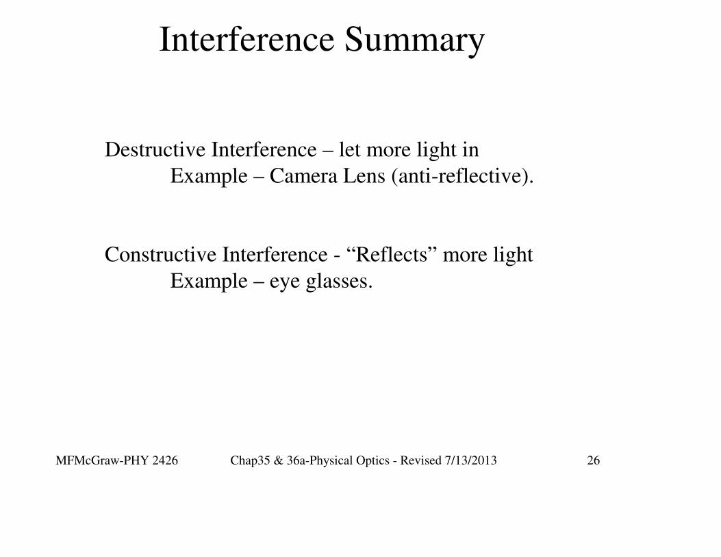
Interference Summary
Destructive Interference – let more light in
Example – Camera Lens (anti-reflective).
Constructive Interference - “Reflects” more light
Example – eye glasses.

MFMcGraw-PHY 2426 Chap35 & 36a-Physical Optics - Revised 7/13/2013 27
Newton’s Rings
Illuminated from above by monochromatic light
Dark rings - destructive interference
Bright rings - constructive interference

MFMcGraw-PHY 2426 Chap35 & 36a-Physical Optics - Revised 7/13/2013 28
Newton’s Rings
Center spot is dark
because difference in
optical path length is zero

MFMcGraw-PHY 2426 Chap35 & 36a-Physical Optics - Revised 7/13/2013 29
Newton’s Rings
Ray 1 is NOT phase shifted at the glass-
air interface
Ray 2 is phase shifted by λ/2 at the air-
glass interface
Dark rings - destructive interference
Bright rings - constructive interference
Dark => 2t = λ
Bright => 2t = λ/2
For the first rings

MFMcGraw-PHY 2426 Chap35 & 36a-Physical Optics - Revised 7/13/2013 30
Newton’s Rings
12
N
1r = N - λR
2
As one moves outward from the center from one dark ring to the next the path
difference increases by the same amount λ, a corresponding increase occurs in
the thickness of the air layer λ /2. The bottom surface of the lens is curved and
the slope of the lens surface increases. Therefore the separation of the rings gets
smaller for the outer rings. The radius of the Nth bright ring is given by

MFMcGraw-PHY 2426 Chap35 & 36a-Physical Optics - Revised 7/13/2013 31
Measurement Using Interference
Normal incidence of monochromatic light light.

MFMcGraw-PHY 2426 Chap35 & 36a-Physical Optics - Revised 7/13/2013 32
What happens on either side of the air
wedge is what counts
Ray 1 is not phase shifted
at the glass-air interface
Ray 2 is phase shifted
at the air-glass
interface
Dark band

MFMcGraw-PHY 2426 Chap35 & 36a-Physical Optics - Revised 7/13/2013 33
What happens on either side of the air
wedge is what counts
Ray 1 is not phase shifted at the
top glass-air interface Ray 2 is phase shifted at the
bottom air-glass interface
First Bright and Dark Lines
1st Bright Line 1st Dark Line
Phase shift already contributes λ /2.
Path length delta needs to
contribute another λ /2.
Phase shift already contributes λ /2.
Path length delta needs to contribute
λ.
λ λ2t = ; t =
2 4λ
λ2t = ; t =
2

MFMcGraw-PHY 2426 Chap35 & 36a-Physical Optics - Revised 7/13/2013 34
t T
T
θ θ
θ
L
2t = nλ = λ
λt =2
Small triangle
Large triangle
λtsinθ = =
s 2s
Tsinθ =
L

MFMcGraw-PHY 2426 Chap35 & 36a-Physical Optics - Revised 7/13/2013 35
2t = nλ = λ
λt =2
Small triangle
Large triangle
λtsinθ = =
s 2s
Tsinθ =
L
t T
T
θ θ
θ
L
D
D
λ T=
2s L
2 LT = = N = #Dark linesλ s
λT = N
2
Ls

MFMcGraw-PHY 2426 Chap35 & 36a-Physical Optics - Revised 7/13/2013 36
Young’s Experiment
Double Slit Interference

MFMcGraw-PHY 2426 Chap35 & 36a-Physical Optics - Revised 7/13/2013 37
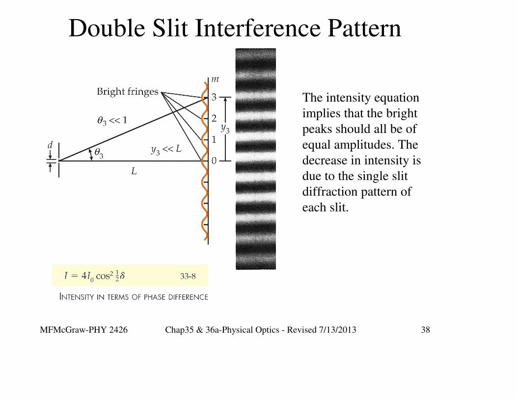
Double Slit Interference Pattern
MFMcGraw-PHY 2426 Chap35 & 36a-Physical Optics - Revised 7/13/2013 38
Double Slit Interference Pattern
The intensity equation
implies that the bright
peaks should all be of
equal amplitudes. The
decrease in intensity is
due to the single slit
diffraction pattern of
each slit.

MFMcGraw-PHY 2426 Chap35 & 36a-Physical Optics - Revised 7/13/2013 39
Double Slit Calculation
mm
-1 mm
ytanθ =
L
yθ = tan
L
mdsinθ = mλ; m = 0,1,2,...
Location of the bright lines

MFMcGraw-PHY 2426 Chap35 & 36a-Physical Optics - Revised 7/13/2013 40
Double Slit Calculation

MFMcGraw-PHY 2426 Chap35 & 36a-Physical Optics - Revised 7/13/2013 41
Both slits need to be open to observe
the interference pattern

MFMcGraw-PHY 2426 Chap35 & 36a-Physical Optics - Revised 7/13/2013 42
Diffraction is the spreading of a wave around
an obstacle in its path and it is common to all
types of waves.
The size of the obstacle must be similar to the
wavelength of the wave for the diffraction to
be observed.
Larger by 10x is too big and
smaller by (1/10)x is too small.
Diffraction

MFMcGraw-PHY 2426 Chap35 & 36a-Physical Optics - Revised 7/13/2013 43
Poisson Spot - Arago Spot

MFMcGraw-PHY 2426 Chap35 & 36a-Physical Optics - Revised 7/13/2013 44
Arago Spot
An Arago spot is a bright point that appears at the center of the
shadow of a circular object in light from a point source. The
spot occurs within the geometrical shadow and no particle
theory of light could account for it. Its discovery provided
strong evidence for the wave nature of light,
In 1818, Siméon Poisson deduced from Augustin Fresnel's
theory, the necessity of a bright spot at the centre of the shadow
of a circular opaque obstacle. With his counterintuitive result
Poisson hoped to disprove the wave theory.
Much to Poisson’s embarrassment Dominique Arago
experimentally verifed the prediction. Dominique Arago
supported Jean-Augustin Fresnel's optical theories, and his
observation of what is now known as the spot of Arago helped
to confirm Fresnel's wave theory of light.

MFMcGraw-PHY 2426 Chap35 & 36a-Physical Optics - Revised 7/13/2013 45
Single Slit Diffraction Pattern

MFMcGraw-PHY 2426 Chap35 & 36a-Physical Optics - Revised 7/13/2013 46
Single Slit Interference Pattern

MFMcGraw-PHY 2426 Chap35 & 36a-Physical Optics - Revised 7/13/2013 47
Single Slit - Minimum (Dark)
Imagine a number of equally separated points on the
wavefront in the single slit opening. Each point is a
source of a spherical wavelet. The angle is chosen
such that the difference in pathlength from each
wavelet source is as shown in the diagram. The waves
from points a half slit width apart are 180o out of
phase and cancel.
Moving to the next pair, a half slit width apart, they
also cancel and so on...
1st Min1st Min
The result is a
minimum at this
special angle

MFMcGraw-PHY 2426 Chap35 & 36a-Physical Optics - Revised 7/13/2013 48
Single Slit - Bright Line
Imagine 5 equally separated points on the
wavefront in the single slit opening. Each point is
a source of a spherical wavelet. The angle is
chosen such that the difference in path length from
each wavelet source is as shown in the diagram.
2nd Max 2nd Max
Following the same argument as in the case of the minimum, these waves
reinforce in pairs and result in a bright spot on the screen.

MFMcGraw-PHY 2426 Chap35 & 36a-Physical Optics - Revised 7/13/2013 49
Single Slit Interference Pattern
y2
mm
-1 mm
ytanθ =
L
yθ = tan
L
Location of the minima
λ
λ
m
m
wsinθ = m
2 2
wsinθ = m ; m = 1,2,...

MFMcGraw-PHY 2426 Chap35 & 36a-Physical Optics - Revised 7/13/2013 50
Single Slit Modulates the Double Slit Pattern
You see both
interference
patterns at the
same time.

MFMcGraw-PHY 2426 Chap35 & 36a-Physical Optics - Revised 7/13/2013 51
http://www.pas.rochester.edu/~ksmcf/p100/java/Optics/Diffraction.html
Interference & Diffraction Demos

MFMcGraw-PHY 2426 Chap35 & 36a-Physical Optics - Revised 7/13/2013 52
http://www.austincc.edu/mmcgraw/physics_simulations.htm
Interference & Diffraction Demos

MFMcGraw-PHY 2426 Chap35 & 36a-Physical Optics - Revised 7/13/2013 53
Diffraction Gratings

MFMcGraw-PHY 2426 Chap35 & 36a-Physical Optics - Revised 7/13/2013 54
Grating Information
Lab gratings: 100, 300 and 600 lines/mm
( 0.100, 0.300 and .600 lines/µm)
These correspond to slit spacings of :
10.0, 3.33 and 1.67 µm
Visible light spectrum
400nm - 700nm
0.400 µm - 0.700 µm
Visible light spectrum
400nm - 700nm
0.400 µm - 0.700 µm
Human Hair
Diam ~ 75-100 µm
Human Hair
Diam ~ 75-100 µm

MFMcGraw-PHY 2426 Chap35 & 36a-Physical Optics - Revised 7/13/2013 55
Transmission Diffraction Grating

MFMcGraw-PHY 2426 Chap35 & 36a-Physical Optics - Revised 7/13/2013 56
Diffraction Grating
mdsinθ = mλ; m = 0,1,2,...
Location of diffraction maxima
At the location of a diffraction
maximum the differences in the
path lengths from the adjacent
slits are equal to a wavelength
mm
-1 mm
ytanθ =
L
yθ = tan
LNdλsin(Θ) = λN

MFMcGraw-PHY 2426 Chap35 & 36a-Physical Optics - Revised 7/13/2013 57
Diffraction Grating - Line Width
min
min
Ndsinθ = λ
λθ =
Nd
N is the total number of slits.
Nd is the total length of the grating
This argument is exactly the same as the
single slit case. The minimum value of
the central peak occurs at θmin . The width
of the peak is 2 θmin .
As the number of slits increases the peaks
become narrower.
MFMcGraw-PHY 2426 Chap35 & 36a-Physical Optics - Revised 7/13/2013 58
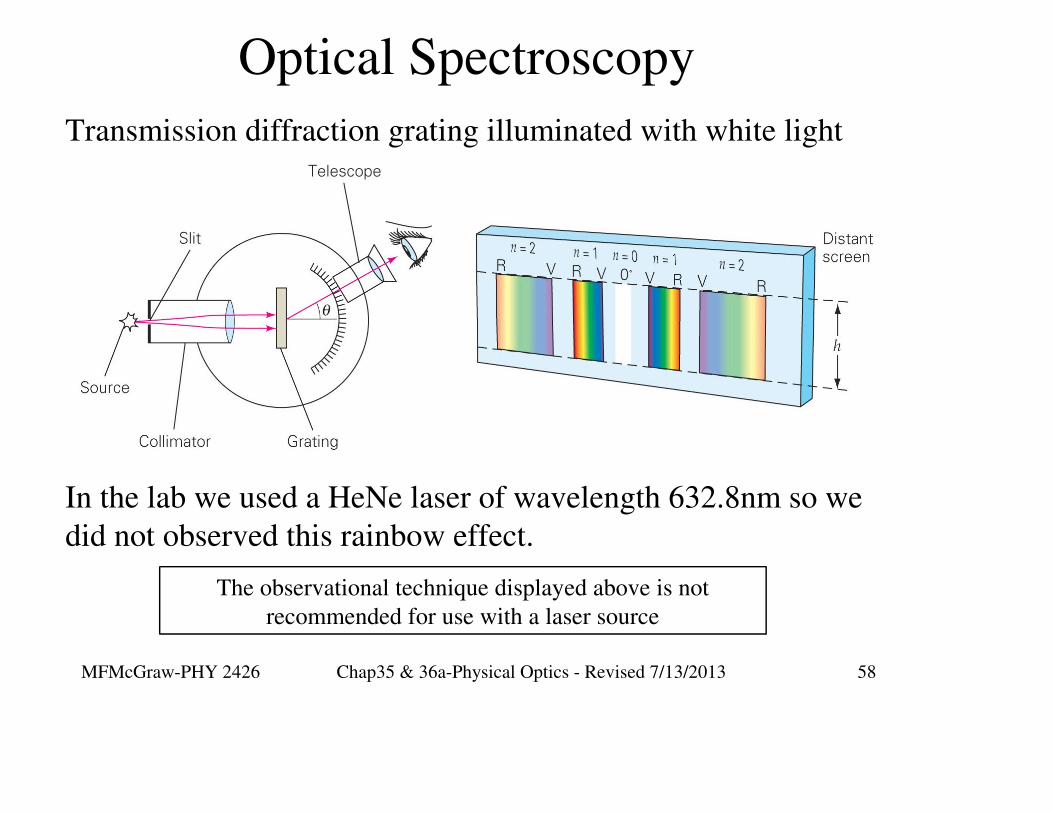
Optical Spectroscopy
Transmission diffraction grating illuminated with white light
In the lab we used a HeNe laser of wavelength 632.8nm so we
did not observed this rainbow effect.
The observational technique displayed above is not
recommended for use with a laser source

MFMcGraw-PHY 2426 Chap35 & 36a-Physical Optics - Revised 7/13/2013 59
Diffraction Grating Resolving Power
≡λ
R = mN∆λ
λN =
m ∆λ
The resolving power (R) of a grating is a measure of its
ability to separate the light of two very close wavelengths
R is defined as the average of the two wavelengths divided by
the absolute value of the difference in the two wavelengths.
The second equation, a rearrangement of the first, gives the
number of slits needed for a given m, λ, and ∆λ.

MFMcGraw-PHY 2426 Chap35 & 36a-Physical Optics - Revised 7/13/2013 60
Diffraction Limited Optics

MFMcGraw-PHY 2426 Chap35 & 36a-Physical Optics - Revised 7/13/2013 61
Optical Limits Due to Diffraction
Question: How close together can two objects be located and
still be resolved by an observer as two distinct objects?
An image formed on the retina, on photographic film (or CCD)
or viewed through a microscope or telescope passes through at
least one circular aperture.
This aperature acts as a single “slit” and causes light from an
object to spread out in a single “slit” diffraction pattern.

MFMcGraw-PHY 2426 Chap35 & 36a-Physical Optics - Revised 7/13/2013 62
Diffraction Limited Optics
Overlapping single slit
diffraction patterns.
As the two point sources move closer together, the angle α
decreases and the overlap of the diffraction patterns increases.

MFMcGraw-PHY 2426 Chap35 & 36a-Physical Optics - Revised 7/13/2013 63
Limits of Resolution - Rayleigh’s CriterionOverlapping single slit
diffraction patterns.
Question: How much overlap is
possible in the diffraction patterns if
the observer is to still be able to
resolve the patterns as due to two
distinct objects?
Rayleigh’s Criterion - The limit for resolving two objects as
being distinct occurs when the maximum of one diffraction
pattern is at the location of the first minimum of the other
diffraction pattern.

MFMcGraw-PHY 2426 Chap35 & 36a-Physical Optics - Revised 7/13/2013 64
Limits of Resolution - Rayleigh’s Criterion
Overlapping single slit
diffraction patterns.
This angular separation
represents the Rayleigh
criterion.
Rayleigh’s criterion
c
λα = 1.22
D
This is similar to the result for the first minimum of the single slit
diffraction pattern: sinθ = λ/a. The 1.22 factor is due to the difference
between a linear slit and a circular aperture.

MFMcGraw-PHY 2426 Chap35 & 36a-Physical Optics - Revised 7/13/2013 65
Limits of Resolution - Rayleigh’s Criterion
The illustration above is for
objects separated by 0.8, 1.0 and
1.2 times the Rayleigh criterion.
The illustration below is for 2
objects separated by the Rayleigh
criterion.

MFMcGraw-PHY 2426 Chap35 & 36a-Physical Optics - Revised 7/13/2013 66
X-Ray Scattering

MFMcGraw-PHY 2426 Chap35 & 36a-Physical Optics - Revised 7/13/2013 67
X-Ray Crystal Scattering Geometry
“Diffraction occurs when each object in a periodic array scatters radiation
coherently, producing concerted constructive interference at specific angles.”
Basics of X-Ray Diffraction, Scott A Speakman, Ph.D., http://prism.mit.edu/xray/BasicsofXRD.ppt

MFMcGraw-PHY 2426 Chap35 & 36a-Physical Optics - Revised 7/13/2013 68
Bragg's Law
“Diffraction occurs when each object in a periodic array scatters radiation
coherently, producing concerted constructive interference at specific angles.”
2dsinΘ = nλ

MFMcGraw-PHY 2426 Chap35 & 36a-Physical Optics - Revised 7/13/2013 69
X-Ray Scattering Geometry
( )ρ
��
i
ikr i k
o
eF e
r
The incident beam amplitude and phase is
represented by the first factor. The second
factor represents the the spatial variation of the
radiation scattered from the atom at ρ.

MFMcGraw-PHY 2426 Chap35 & 36a-Physical Optics - Revised 7/13/2013 70
X-Ray Scattering Wave Vectors
ddsfgddg
( )
� � �
�
'∆k = k - k
∆k = 2ksinΘ = 4π / λ sinΘ

MFMcGraw-PHY 2426 Chap35 & 36a-Physical Optics - Revised 7/13/2013 71
The discrete points represent the lattice points of the reciprocal lattice
of the crystal. The Bragg condition is shown here as a requirement that
the difference of the incident and scattered wavevectors be a reciprocal
lattice vector.
Ewald Sphere
MFMcGraw-PHY 2426 Chap35 & 36a-Physical Optics - Revised 7/13/2013 72
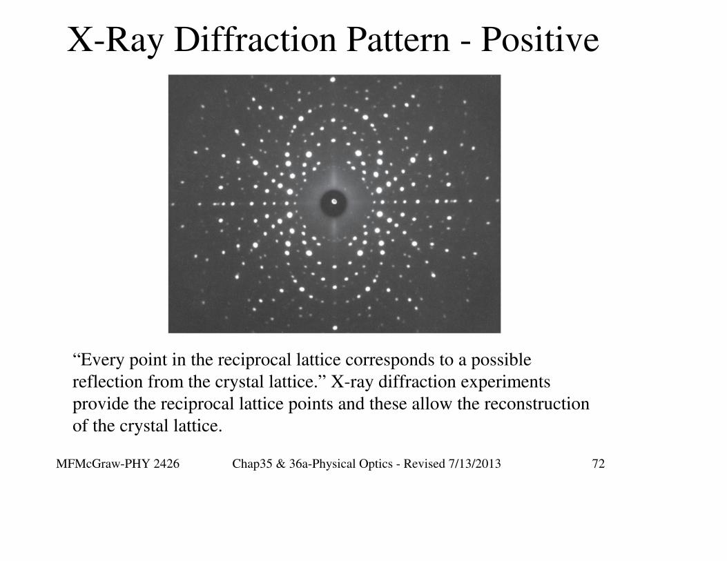
X-Ray Diffraction Pattern - Positive
“Every point in the reciprocal lattice corresponds to a possible
reflection from the crystal lattice.” X-ray diffraction experiments
provide the reciprocal lattice points and these allow the reconstruction
of the crystal lattice.

MFMcGraw-PHY 2426 Chap35 & 36a-Physical Optics - Revised 7/13/2013 73
`~
X-Ray Powder Diffraction Camera