chapter 3c. object markers paragraphs 5 …€¦ · mutcd 2003 california supplement page 3c-4 may...
TRANSCRIPT
MUTCD 2003 California Supplement Page 3C-1
May 20, 2004
CHAPTER 3C. OBJECT MARKERS
Section 3C.01 Object Marker Design and Placement HeightStandard:
Paragraphs 5 (“When used for…”) and 6 (“When used to…”) are deleted. Figure 3C-101 shall beused for mounting height of object markers.In Paragraph 2 (“When used…”), the following types of object markers are added:
CA Type L Utility Pole marker shall be yellow retroreflective material consisting of three 50 x 300mm (2 x 12 in) horizontal rectangles arranged vertically on a utility pole as shown in Figure 3C-101.
CA Type Q object marker shall be a vertical tubular marker, with a height of 450 to 600 mm (18 to24 in) and a minimum cross sectional dimension of 57 mm (2 ¼ in). The yellow retroreflective materialshall consist of three bands, each 75 mm (3 in) in height or a single band 225 mm (9 in) in height asshown in Figure 3C-101.
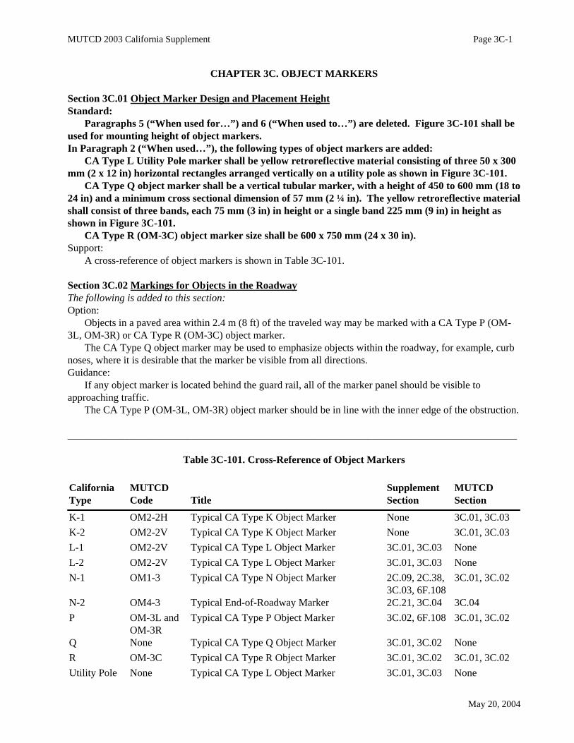
CA Type R (OM-3C) object marker size shall be 600 x 750 mm (24 x 30 in).Support:
A cross-reference of object markers is shown in Table 3C-101.
Section 3C.02 Markings for Objects in the RoadwayThe following is added to this section:Option:
Objects in a paved area within 2.4 m (8 ft) of the traveled way may be marked with a CA Type P (OM-3L, OM-3R) or CA Type R (OM-3C) object marker.
The CA Type Q object marker may be used to emphasize objects within the roadway, for example, curbnoses, where it is desirable that the marker be visible from all directions.Guidance:
If any object marker is located behind the guard rail, all of the marker panel should be visible toapproaching traffic.
The CA Type P (OM-3L, OM-3R) object marker should be in line with the inner edge of the obstruction.
_______________________________________________________________________________________
Table 3C-101. Cross-Reference of Object Markers
CaliforniaType
MUTCDCode Title
SupplementSection
MUTCDSection
K-1 OM2-2H Typical CA Type K Object Marker None 3C.01, 3C.03K-2 OM2-2V Typical CA Type K Object Marker None 3C.01, 3C.03L-1 OM2-2V Typical CA Type L Object Marker 3C.01, 3C.03 NoneL-2 OM2-2V Typical CA Type L Object Marker 3C.01, 3C.03 NoneN-1 OM1-3 Typical CA Type N Object Marker 2C.09, 2C.38,
3C.03, 6F.1083C.01, 3C.02
N-2 OM4-3 Typical End-of-Roadway Marker 2C.21, 3C.04 3C.04P OM-3L and
OM-3RTypical CA Type P Object Marker 3C.02, 6F.108 3C.01, 3C.02
Q None Typical CA Type Q Object Marker 3C.01, 3C.02 NoneR OM-3C Typical CA Type R Object Marker 3C.01, 3C.02 3C.01, 3C.02Utility Pole None Typical CA Type L Object Marker 3C.01, 3C.03 None

MUTCD 2003 California Supplement Page 3C-2
May 20, 2004
MUTCD 2003 California Supplement Page 3C-3
May 20, 2004
MUTCD 2003 California Supplement Page 3C-4
May 20, 2004
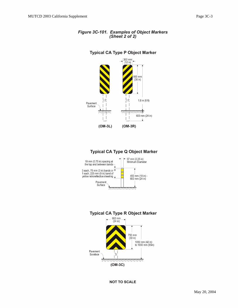
Figure 3C-1. Object Markers and End-of-Roadway MarkersStandard:
The Typical Type 3 Object Marker (OM-3C) shown in this MUTCD figure shall not be used inCalifornia. The CA Type R Object Marker (OM-3C) (size 600 x 750 mm (24 x 30 in)) as shown inFigure 3C-101 shall be used instead.
Section 3C.03 Markings for Objects Adjacent to the RoadwayThe following is added to this section:Option:
Objects outside of the paved shoulder, within 3.6 m (12 ft) of the traveled way, may be marked with CAType L object markers.
The CA Type L (OM2-2V and OM2-2H) object markers may be placed in front of, alongside of, orattached to the object. Where objects are very close to each other, only the first object may need to bemarked.
The CA Type L Utility Pole marker may be used to mark a utility pole.Standard:
If used on State highways, CA Type L-1 (OM2-2V) object marker shall be used instead of CAType L-2 (OM2-2V).Guidance:
If used, the utility company should be responsible for installing and maintaining the CA Type L UtilityPole marker.Support:
See Section 2C.09 and 2C.38 for use of CA Type N-1 (OM1-3) object markers in conjunction with One-Directional Large Arrow (W1-6) and Two-Direction Large Arrow (W1-7) signs for abrupt changes in theroadway alignment.
See Section 6F.108 for use of CA Type N, P and R object markers for temporary traffic control.
Section 3C.04 End-of-Roadway MarkersStandard:
Paragraph 3 (“The end-of-roadway…”) is deleted and replaced with the following:The end-of-roadway marker shall be used at the end of a road or cul-de-sac street where there is
no alternate vehicular path.Paragraph 5 (“The minimum mounting…”) is deleted. Figure 3C-101 shall be used for mounting
height of the end-of-the-roadway marker.The following is added to this section:Support:
See Section 2C.21 for use of end-of-roadway marker in conjunction with END (CA Code W31) sign.

MUTCD 2003 California Supplement Page 3D-1
May 20, 2004
CHAPTER 3D. DELINEATORS
Section 3D.02 Delineator DesignThe following is added to this section:Support:
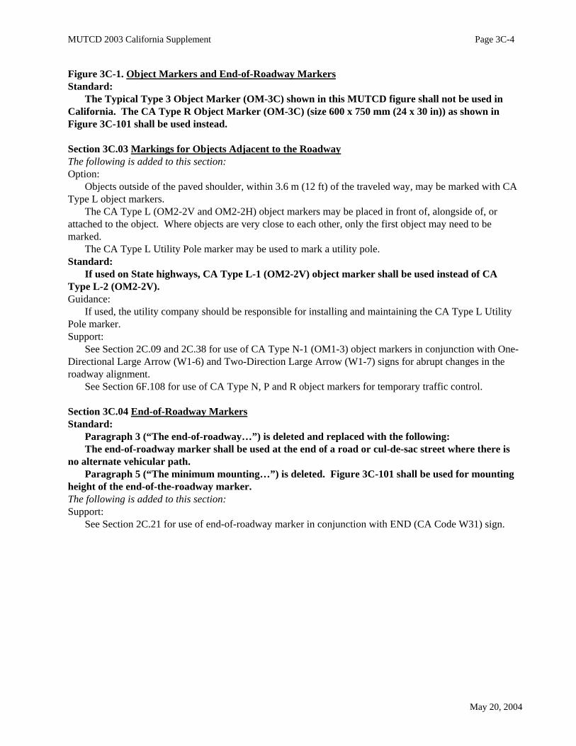
There are two classes of delineator posts and several types of retroreflectorization as shown in Figure3D-101.
Section 3D.03 Delineator ApplicationStandard:
Paragraph 6 (“Double or vertically…”) is deleted.Paragraph 7 (“Red delineators…”) is deleted. In California, red markers are used for wrong-way
traffic, not delineators.The following is added to this section:Option:
Where delineation is required within a paved area, surface mounted channelizers may be used. SeeSection 3F.02.Standard:
The color of the delineator retroreflectors shall conform to the color of edge lines except for the useof yellow on the right at narrow bridges and red at truck escape ramps.Support:
Examples of the use of delineators are shown in Figure 3D-101. Color exceptions are shown in Figure3D-103 and 3D-104.
Following are typical delineators and their uses:• Type E - White Retroreflector (2 Sided). For use on the left or right of 2-lane 2-way streets and
highways when it is desirable to have a reflector on the front, and one on the back of the delineatorfacing the opposite direction of traffic.
• Type F - White Retroreflector (1 Sided). For use on the right of freeways and expressways. Theymay also be used on 2-lane 2-way streets and highways when the Type E is not needed.
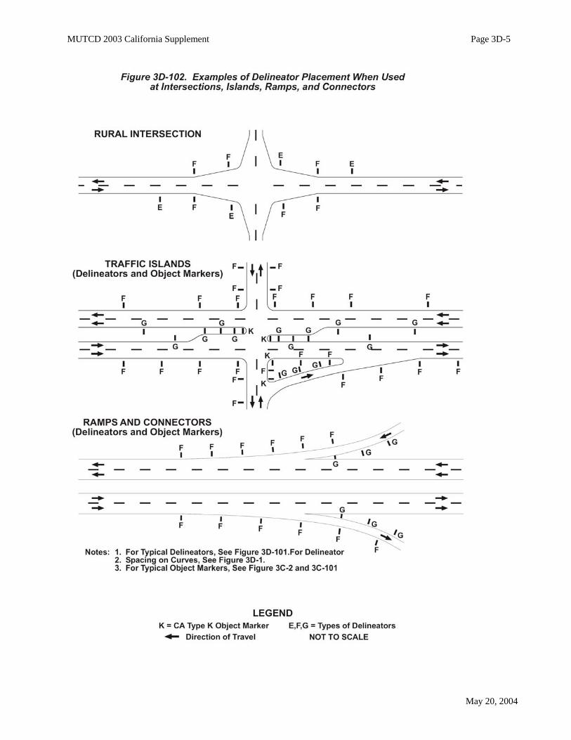
• Type G - Yellow Retroreflector (1 Sided). For use on the left of divided highways and 2-lanehighway intersections as shown in Figure 3D-102.
• Type I - Yellow Retroreflector (2 Sided). For use at approaches to narrow bridges as shown inFigure 3D-104.
• Type J - Red Retroreflector (1 Sided). For placement on both sides of Truck Escape Ramps asshown in Figure 3D-103.
Section 3D.04 Delineator Placement and SpacingGuidance:
In Paragraph 1 (“Delineators should…”) second sentence (“They should be…”), the phrase “0.6 to 2.4 m(2 to 8 ft)” is changed to “0.6 to 1.8 m (2 to 6 ft)”.
Paragraph 3 (“Delineators should be spaced…”) is deleted and replaced with the following:Delineators should be spaced 160 m (530 ft) apart on mainline tangent sections. Delineators should be
spaced 60 m (200 ft) apart on ramp tangent sections.The following is added to this section:Guidance:
Installations should be inspected at night to ensure that there are no confusing or misleading delineators.Standard:
Unless local conditions justify otherwise, delineators shall be placed on all State highways.

MUTCD 2003 California Supplement Page 3D-2
May 20, 2004
Guidance:Delineators should also be provided on all city and county roads.When used, delineators should be placed as follows:a On the outsides of highway curves of 915 m (3000 ft) radius or less (including medians in divided
highways), freeway exit and entrance ramps and connectors. Exception to this, is where a medianbarrier is delineated as shown in the Median Barrier Delineation Detail in Figure 3D-105. Delineatorspacing on curves is shown in Figure 3D-1 and Table 3D-1.
b On the right of tangent sections of freeway entrance and exit ramps, collector roads, freewayconnectors and lane reduction transition sections at 60 m (200 ft) spacing.
c On embankments higher than 3.0 m (10 ft) and with side slopes steeper than 1:4. Delineator spacingis approximately 160 m (525 ft).
d On approaches to narrow bridges as shown in Figure 3D-104.e On tangent sections of rural State highways where there are no reflective pavement markers, such as
in snow areas. Delineator spacing is approximately 160 m (525 ft).f On all new guardrail or bridge rail installations, or when maintenance is required on existing
guardrail or bridge rail, within 3.66 m (12 ft) of the edge of traveled way and curves of 915 m (3000ft) radius or less. The spacing on tangent sections is approximately 160 m (525 ft). For spacing oncurves, see Figure 3D-1 and Table 3D-1.
Option:Delineators may also be placed as follows:a At intersections, road approaches, and median openings, as shown in Figure 3D-102.b On sections of highway with non-standard shoulder width.
Section 3D.101 Culvert MarkersSupport:
Culvert markers are placed as a convenience to maintenance crews in marking locations of culvertopenings. Such marking is sometimes necessary to protect culvert ends from damage from adjacentoperations as well as to serve as an aid in locating culverts during storm conditions.
Refer to Department of Transportation’s Maintenance Manual, Chapter M5 (Traffic Safety Devices) formore information on culvert markers. See Section 1A.11 for information regarding this publication.Option:
Culvert markers may be placed on both sides of the highway at those culverts where they are necessary. Guidance:
Culvert markers should be so placed as not to interfere with a line of delineators.Standard:
Culvert markers shall not be retroreflective, or contain kilometer post marker information.
Section 3D.102 Emergency Passageway MarkerSupport:
Except for emergency passageways in median barriers, median openings are not allowed on freeways. Refer to Department of Transportation’s Traffic Manual, Section 7-04.7 for design considerations of
emergency passageways. See Section 1A.11 for information regarding this publication.Guidance:
Where freeway median passageways are provided for emergency vehicles, delineation for the crossovershould be as follows:
a At a point, 320 m (1/5 mi) in advance of the crossover, one Class 1 Delineator, with a yellow postand two 75 x 300 mm (3 x 12 in) white retroreflectors stacked vertically (600 mm (24 in) of whiteretroreflectance), should be placed on the left side of the through roadway facing approaching traffic.

MUTCD 2003 California Supplement Page 3D-3
May 20, 2004
b At a point, 160 m (1/10 mi) in advance of the crossover, one Class 1 Delineator, with a yellow postand two 75 x 300 mm (3 x 12 in) yellow retroreflectors stacked vertically, should be placed on theleft side as in (a).
c At the far side of the crossover, one Class 1 Delineator, with a yellow post and one 75 x 300 mm (3 x12 in) white retroreflector over one 75 x 300 mm (3 x 12 in) yellow retroreflector stacked vertically,should be placed on the left side as in (a).
Section 3D.103 Narrow Bridge Signing and MarkingSupport:
The placement of warning signs, object markers, delineators, and edge lines at narrow bridges isdependent upon the width of the bridge and approach roadway. Standard:
Narrow bridge signing and marking shall conform to the details shown in Figure 3D-104.
Section 3D.104 Median Barrier DelineationGuidance:
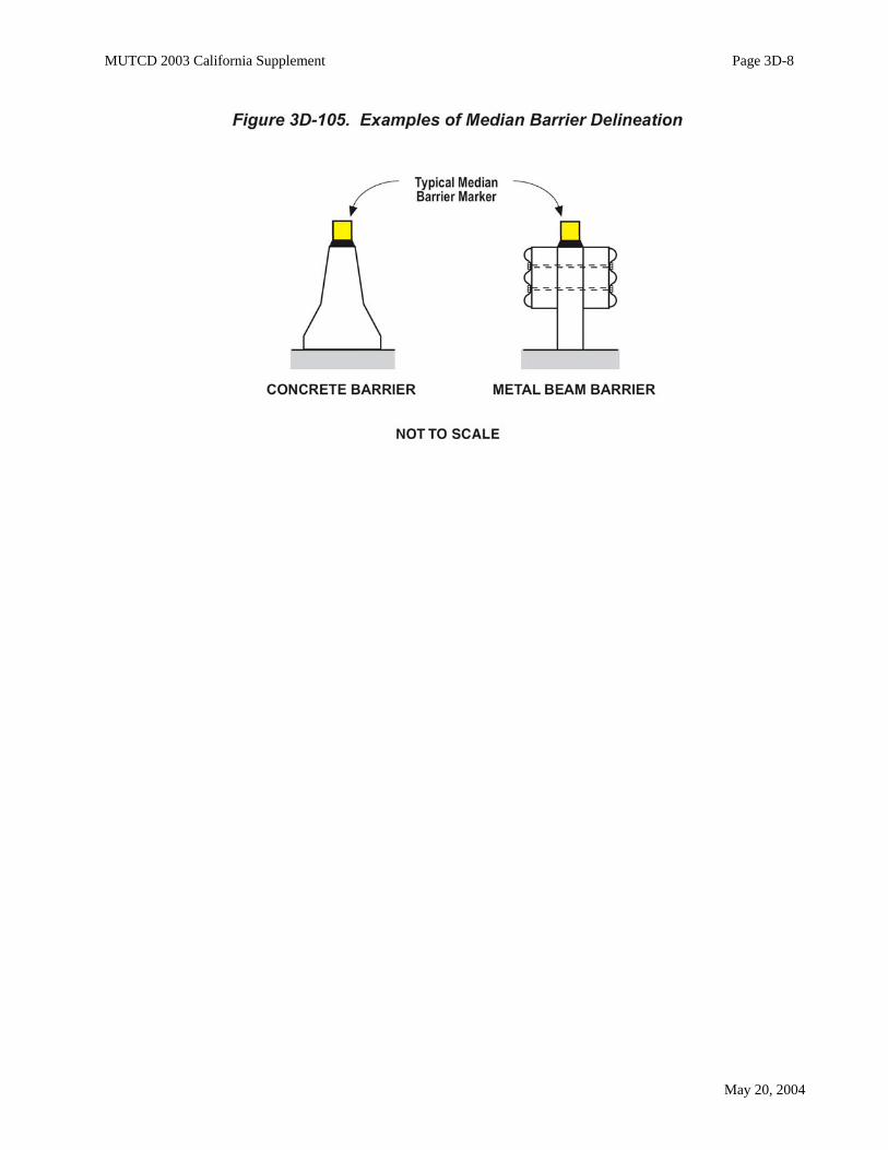
Median barriers should be delineated when the clearance between the barrier and the edge of traveledway is less than 2.44 m (8 ft).
In general, when delineated, it should be with an approved median barrier marker, the same color as theleft edge line. They should be placed on top of the barrier at 14.64 m (48 ft) centers.
Markers placed on the sides of barriers, near the splash zone, should be avoided because of the tendencyto collect dirt which reduces their effectiveness. See Figure 3D-105.
MUTCD 2003 California Supplement Page 3D-4
May 20, 2004
MUTCD 2003 California Supplement Page 3D-5
May 20, 2004

MUTCD 2003 California Supplement Page 3D-6
May 20, 2004

MUTCD 2003 California Supplement Page 3D-7
May 20, 2004
MUTCD 2003 California Supplement Page 3D-8
May 20, 2004

MUTCD 2003 California Supplement Page 3E-1
May 20, 2004
CHAPTER 3E. COLORED PAVEMENTS
Support:No Comments. This MUTCD Chapter is adopted as is for California.
MUTCD 2003 California Supplement Page 3F-1
May 20, 2004
CHAPTER 3F. BARRICADES AND CHANNELIZING DEVICES
Section 3F.02 Channelizing DevicesStandard:
Paragraphs 1 (Channelizing devices…”) through 9 (“When 700 mm…”) are deleted and shall notbe applicable in California. In California, cones are used for temporary traffic control, not aspermanent channelizing devices.The following is added to this section:Support:
Channelizers are flexible retroreflectorive devices for installation within the roadway to discouragemotorists from crossing a line or area of the roadway. Unlike delineators, which indicate the roadwayalignment, channelizers are intended to provide additional guidance and/or restriction to traffic bysupplementing pavement markings and delineation. Option:
Channelizers may be used for additional emphasis to discourage median crossings at traffic islands andat lane separations.Standard:
The design of a channelizer shall be as shown in Figure 3F-101.The retroreflective unit used on channelizers shall be a minimum of 75 x 300 mm (3 x 12 in). The
75 x 300 mm (3 x 24 in) minimum retroreflective unit shall be visible at 300 m (1000 ft) at night underillumination of legal high beam headlights, by persons with vision of or corrected to 20/20. Refer toDepartment of Transportation’s Standard Specifications Section 12-3.07. See Section 1A.11 forinformation regarding this publication.
The post shall be flexible with a 57 mm (2 ¼ in) minimum width, except that the portion containingthe retroreflective unit shall be a minimum width of 75 mm (3 in). The post shall be a minimum heightof 900 mm (36 in) above the pavement on State highways.
Channelizer posts used for temporary traffic control shall be orange with white reflectors. SeeSection 6F.101.
If the channelizers are to remain in place as a permanent roadway feature, the post shall be whiteand the color of the reflector shall conform to that of the pavement markings it supplements with thefollowing exceptions:
• Retroreflective units used in narrow bridge shoulder tapers shall be yellow as shown in Figure3D-104.
• Retroreflective units shall be white when used in construction and maintenance zones (postsshall be orange). See Section 6F.101.
Option:At locations where speeds are 65 km/h (40 mph) or less a minimum post height of 700 mm (28 in) may
be used.Support:
Since channelizers require closer spacing, their post size requirements differ from those of delineators.There are two basic types of channelizers: one attaches to the pavement and the other attaches to an
anchoring device imbedded in the pavement. Both the base and anchor systems are designed to permitreplacement of the channelizer post. See Figure 3F-101.Guidance:
Channelizers should be placed a minimum of 0.61 m (2 ft) from the traffic line, away from traffic, toallow for future maintenance of the line. Option:
Space limitations may dictate exceptions to this criteria. At certain locations, placement directly on thetraffic line may be required.

MUTCD 2003 California Supplement Page 3F-2
May 20, 2004
Support:Spacing of the channelizers depends on the type of facility where they are to be used, the speed and
volume of traffic, and the alignment to be channelized. Spacing which results in a visual fence/barrier effectis a key factor in channelizer installation.Guidance:
The maximum post spacing should be 30 m (100 ft) on carpool lanes where channelizers are usedprimarily to delineate the separation between the carpool lane and the main facility.
In locations where a relatively high number of violations occur, the post spacing should be 7.5 m (25 ft).
Option:Where barrier violations are relatively minimal, a post spacing of 15 m (50 ft) may be adequate.
However, spacing in excess of 15 m (50 ft) is of negligible value as a deterrent to intentional barrierviolations.
Post spacing closer than 7.5 m (25 ft) may be considered on lower speed roads, urban streets and atspecific locations such as traffic islands.
MUTCD 2003 California Supplement Page 3G-1
May 20, 2004
CHAPTER 3G. ISLANDS
Section 3G.01 GeneralThe following is added to this section:Support:
On State highways, criteria for the design of islands are set forth in Department of Transportation’sHighway Design Manual. See Section 1A.11 for information regarding this publication.
Section 3G.02 Approach-End TreatmentStandard:
Paragraphs 2 (“Approach-end markings…”) through 6 (“Pavement markings…”) are deleted forapplication in California. Use Section 3B.106 for the rumble strips topic, instead.
Section 3G.03 Island Marking ApplicationStandard:
The Option and Guidance topics shall be deleted for application in California. Use Section 3B.106for the rumble strips topic, instead.
Paragraphs 3 (“As indicated…”) and 4 (“When raised bars…”) are deleted for application inCalifornia. Use Section 3B.106 for the rumble strips topic, instead.The following is added to this section:Standard:
Double solid 100 mm (4 in) wide yellow lines shall be used to delineate the edge of a median islandwhere the median is an all-paved, at-grade section of the highway. The island formed by doubleyellow lines shall be at least 0.61 m (2 ft) in width, as shown in Figure 3A-107.
When used, other markings in the median island area shall be yellow.Support:
This treatment is not intended for freeways or other highways with a positive barrier in the median.Single solid yellow left edge line and markers as shown in Figure 3A-105 are standard.
The use of channelizing lines are shown in Figure 3A-112 and no-passing markings are shown in Figures3A-104 and 3B-13.
Section 3G.06 Island DelineatorsStandard:
Paragraph 1 (“Delineators installed…”) is deleted and replaced with the following:Delineators installed on islands shall be the same colors as the related edge lines.
Support:In California, red markers are used for wrong-way traffic, not delineators.