chapter 4-3: processes and oisoperating systemsocw.snu.ac.kr/sites/default/files/note/2538.pdf ·...
TRANSCRIPT

Chapter 4-3: Processes and O i SOperating Systems
Soo-Ik Chae
High Performance Embedded Computing 1
Topicsp
Priority ceiling protocol (PCP)
Performance estimation and Scheduling g
Languages and scheduling
O ti t h i dOperating systems mechanisms and overhead.
Embedded file systems.
High Performance Embedded Computing 2

Priority ceiling protocoly g p
High Performance Embedded Computing 3
PCP Protocol Definition (1)( )
High Performance Embedded Computing 4

PCP Protocol Definition (2)( )
High Performance Embedded Computing 5
PCP Example (1)p ( )
High Performance Embedded Computing 6

PCP Example (2)p ( )
High Performance Embedded Computing 7
PCP Example (3)p ( )
High Performance Embedded Computing 8

PCP Propertiesp
High Performance Embedded Computing 9
Performance Estimation (1)( )
Assumption that the computation time of a process is fixed is not very realisticExecution time depends on
D t d d t thData dependent pathCache
Strong interests on effects of multiple tasks on the cacheStrong interests on effects of multiple tasks on the cacheA segmented locked cache
A program can lock a part of the cache so that no other program could modify those cache locations.This would allow the program to certain parts of itself in the cache after a preemption.p pIt reduces the cache size not only for the program with the lock bust also for other programs in the system.
High Performance Embedded Computing 10

Performance Estimation Compiler support for software-based cache partitioning [Mueller][Mueller]
High Performance Embedded Computing 11
Software-based cache partitioningp g
High Performance Embedded Computing 12

Software-based cache partitioningp gPartitioning the cache for use by multiple processes.
High Performance Embedded Computing 13
Software-based cache partitioningp g
High Performance Embedded Computing 14

Software-based cache partitioningp g
High Performance Embedded Computing 15
Software-based cache partitioningp g
High Performance Embedded Computing 16

Cache modeling and schedulingg gLi and Wolf developed a model for multitasking in caches.
h h t bl f t i t i th heach process has a stable footprint in the cache.
Each process was modeled with a two-state model:Process is in the cacheProcess is in the cache.
Process is not in the cache.
Total state of the cache is given by the union of all the models for g ythe processes that use the cache.
The performance of a process is modeled by two major d bmeasured numbers
The worst-case execution time when the process is not in the cachecache
The average-case execution time when the process is in the cache.
High Performance Embedded Computing 17
Cache modeling and schedulingg g
Given the cache model and the performance characteristics of each process, they constructed an abstract schedule that approximated the execution time of the multitasking systemof the multitasking system.
Fig. 10: accuracy Average error: less than 10%Average error: less than 10%
High Performance Embedded Computing 18

Languages and schedulingg g g
Programming languages can capture information about tasks and inter-process communication.
C il ti t i li d i l t tiCompilation can generate specialized implementations, implement static schedules.
Let look at languages that provide task level models forLet look at languages that provide task-level models for system activity.
High Performance Embedded Computing 19
Codesign finite state machines (CFSMs)g ( )
A control model explicitly designed to be implemented as combinations of hardware and softwarecombinations of hardware and software.A CFSM repeatedly executes a four-phase cycle:
IdleIdle.Detect input events.Go to new state based on current state and inputsGo to new state based on current state and inputs.Emit outputs.
A CFSM is modeled by an automaton with one-input y pbuffers for each input and one-input buffers for each output.
High Performance Embedded Computing 20

Static scheduling using Petri netsg g
Lin and Zhu developed an algorithm for statically scheduling processes using Petri nets.
Given a Petri net model for a process, find maximal li f t f th h d l ti iacyclic fragments of the process, schedule operations in
each fragment.
Expansion of a Petri net: acyclic Petri net in whichExpansion of a Petri net: acyclic Petri net in which every transition has one input or output place,
at least one place with no input transitions (initial places)at least one place with no input transitions, (initial places)
at least one place with no output transitions (cut-off places)
High Performance Embedded Computing 21
Static scheduling using Petri netsg g
Maixmal expansion of G with respect to m, E is p pan acyclic Petri net with the following properties
The initial place correspond to m (initial marking)p p ( g)
The cut-off places correspond to the set of places encountered when a cycle has been reached
E is transitively closed: for each transition or place in E, all preceding places and transitions reachable form m
l i Eare also in E
Code is generated form maximally expanded fragment by pre-ordering operations.
High Performance Embedded Computing 22

Static scheduling using Petri netsg g
Constructing a Petri net model from a program of communicating processes.
High Performance Embedded Computing 23
Static scheduling using Petri netsg g
High Performance Embedded Computing 24

Maximal expansionsp
High Performance Embedded Computing 25
Software thread integrationg
Dean: schedule multiple pthreads statically in a single program.Primary thread has real-timePrimary thread has real time requirements.Secondary thread does not have real-time requirementshave real time requirements.STI copies portions of the primary thread into the secondary thread so that thesecondary thread so that the primary thread execute correctly and meets its deadlinesdeadlines.
No context switchingReduce execution time
High Performance Embedded Computing 26
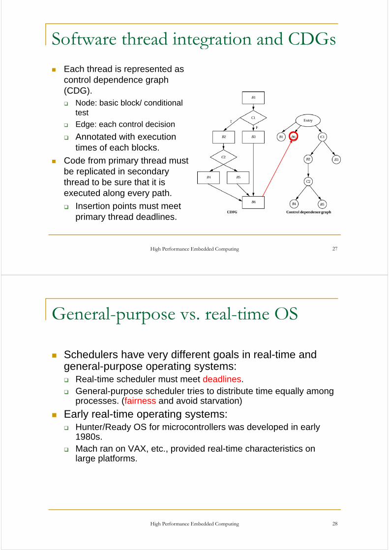
Software thread integration and CDGsg
Each thread is represented as l d d hcontrol dependence graph
(CDG).Node: basic block/ conditional test
Edge: each control decision
Annotated with executionAnnotated with execution times of each blocks.
Code from primary thread must be replicated in secondary thread to be sure that it is executed along every path.
Insertion points must meet primary thread deadlines.
High Performance Embedded Computing 27
General-purpose vs. real-time OSp p
S h d l h diff t l i l ti dSchedulers have very different goals in real-time and general-purpose operating systems:
Real-time scheduler must meet deadlines.Real time scheduler must meet deadlines.General-purpose scheduler tries to distribute time equally among processes. (fairness and avoid starvation)
Early real time operating systems:Early real-time operating systems:Hunter/Ready OS for microcontrollers was developed in early 1980s.Mach ran on VAX, etc., provided real-time characteristics on large platforms.
High Performance Embedded Computing 28

Memory managementy g
Memory management allows RTOS to run outside applications. (protection)
C ll h d l d d i t ll dCell phones run downloaded, user-installed programs.
Memory management helps the RTOS manage a large virtual address spacevirtual address space.
Flash may be used as a paging device.
High Performance Embedded Computing 29
Windows CE memory managementy g
Flat 32-bit address space.
Top 2 GB for kernel.
Statically mapped.
Bottom 2 GB for user processes.
High Performance Embedded Computing 30

WinCE user memory spacey p
64 l t f 32 MB h64 slots of 32 MB each.Slot 0 is currently running process
Slot 63: resource mappingsprocess.Slots 1-33 are the processes.
Slots 34-62: object store,memory mapped filesp
32 processes max.Object store, memory
d filSlot 3: process
…
mapped files, resource mappings.
Slot 1: DLLs
Slot 2: process
Slot 0: current process
Slot 1: DLLs
High Performance Embedded Computing 31
Mechanisms for real time operationp
T k h i f l tiTwo key mechanisms for real time:Interrupt handler.Scheduler.Scheduler.Interrupt must be carefully handled to avoid destroying the real-time properties of the OS.
Interr pt handler is part of the priorit s stem Interr ptsInterrupt handler is part of the priority system. Interrupts have priorities set in hardware. These priorities supersede process priorities of the processes.p p p p
Can be seen as a distinct set of processes that are separate form the operating system’s regular processes.Should spend as little time as possible in the interrupt handlersShould spend as little time as possible in the interrupt handlers that are dispatched by the hardware interrupt system.
High Performance Embedded Computing 32

Interrupt handling in RTOSsp g
But many real devices need a significant amount of computation to be done somewhere.
As a result, device oriented processing is often divided into two sections: an interrupt service routine (ISR) and an interrupt service thread (IST)an interrupt service thread (IST).
ISR is dispatched by the hardware interrupt system while IST is a user-mode processIST is a user-mode process
Scheduler determines ability to meet deadlines.
High Performance Embedded Computing 33
Windows CE interruptsp
Two types of ISRs:Static ISRs are built into kernel, one-way ycommunication to IST.
Installable ISR can be dynamically loaded, uses y yshared memory to communicate with IST.
High Performance Embedded Computing 34

Static ISR
Built into the kernel.SHx and MIPS must be written in assembler, limited register availabilityregister availability.
One-way communication from ISR to IST.C h b ff b t l ti t b d fi dCan share a buffer but location must be predefined.
Nested ISR support based on CPU.
Stack is provided by the kernel.
High Performance Embedded Computing 35
Installable ISR
Can be dynamically loaded into kernel.
Loads a C DLL (dynamically linked library).
Can use shared memory for communication.
ISRs are processed in the order they were installed.
Limited stack size.
High Performance Embedded Computing 36

Interrupt latencyp y
ISRAmount of time that interrupts are turned off
Time required to visit ISR save registers etcTime required to visit ISR, save registers, etc.
ISTTime spent in ISRTime spent in ISR
Time spent in Kernel call
Thread scheduling time
High Performance Embedded Computing 37
WinCE 4.x interruptsp
thI
hreadIST processing
OI-IS
RISR ISR
kO
ALISR ISR
kernel
ISH Set event Enable ID
All higherenabled
HWAll enabled
Except IDAll enabled
device
High Performance Embedded Computing 38

Operating system overheadp g y
Rhodes and Wolf studied context switching overhead using simulation.
T CPU t ith bTwo-CPU system with bus.
100 random task graphs.
V i t f l k 10% 20% 40%Varying amounts of slack: none, 10%, 20%, 40%.
High Performance Embedded Computing 39
OS overhead results
High Performance Embedded Computing 40[Rho99] © 1999 IEEE Computer Society

Interprocess communicationp
IPC often used for large-scale communication in general-purpose systems.
M ilb i li d i d f ll f tMailboxes are specialized memories, used for small, fast transfers.
A writer and many readersA writer and many readers
Multimedia systems can be supported by quality-of-service (QoS) oriented inter-process communication se ce (QoS) o e ed e p ocess co u ca oservices.
Streaming and large transfers
High Performance Embedded Computing 41
Power managementg
Advanced Configuration and Power Management (ACPI) standard defines power management levels:
G3 mechanical offG3 mechanical off.
G2 soft off: OS need to be rebooted when leaving the state
G1 sleeping.p g
G0 working.
Legacy state: NON-ACPI power modes.
High Performance Embedded Computing 42

Embedded file systemsy
Generally means flash memory storage.
Many embedded file systems need to be compatible with PCPCs.
Some file systems are primarily for reading, others for reading and writingreading and writing.
High Performance Embedded Computing 43
Flash memory characteristicsy
Flash is electrically erasable.
Two types of flash:NOR flash operates similar to RAM.
Used to store executable code
More reliable, faster read, random access capability, , p y
NAND is block oriented, gives more transient failures.Higher density, lower cost, faster write and erase time
L i lifLonger re-write life expectancy
Prone to single bit errors
NAND gets faster, may dominate in future.g , y
High Performance Embedded Computing 44

Flash memory characteristicsy
Block writingFlash cannot be written word-by-word as with RAM.
Fl h t fi t b d i l bl k d thFlash memory must first be erased in large blocks and then written
Block size may be as large as 64KBy g
Erasing a block is considerably larger than a typical magnetic disc sector.
Flash memory wears out during writing.Early memories lasted for 10,000 cycles.
M d i l t f 1 illi lModern memories last for 1 million cycles.
High Performance Embedded Computing 45
Flash Memory CharacteristicsFlash Memory Characteristics
O tiOperationsRead
Write or Program 1 1 1 1 1 1 1 1Write or Program
Changes state from 1 to 0
Erase write
1 1 1 1 1 1 1 1
Changes state from 0 to 1
Uniterase
1 0 1 1 0 0 1 0
Page (sector)
Read/Write unit (in NAND)
Bl k
erase
1 1 1 1 1 1 1 1
Block
Erase unit
High Performance Embedded Computing 46

Comparison of NOR and NAND Flashp
High Performance Embedded Computing 47
Comparison of NOR and NAND Flashp
High Performance Embedded Computing 48

Wear levelingg
Flash memory systems move data to equalize wear during writes.
Fil ll ti t bl t th t it t bFile allocation table gets the most writes---must be moved as well.
Formatting avoids multiple writes to file allocation tableFormatting avoids multiple writes to file allocation table.
High Performance Embedded Computing 49
Virtual mappingpp g
Virtual mapping system stands between file API and physical file system:
File systemfile system:
Schedules erasures.
Consolidates data to empty an
Virtual address
p yentire block
Identifies bad blocks.
M d t f l li
Virtual mapping system
Physical addressMoves data for wear leveling.
Virtual mapping system keeps a table to translate virtual to
Flash memory
y
table to translate virtual to physical addresses.
High Performance Embedded Computing 50

Log-structured file systemg y
Stores log of changes to file, not the original file.Also known as journaling.
Developed for general purpose systems useful for flashDeveloped for general-purpose systems, useful for flash.
Journaling Flash File System (JFFS) maintains consistency during power lossesconsistency during power losses.
Yet Another Flash Filing System (YAFFS) is log-structured file system for NAND flash.s uc u ed e sys e o as
High Performance Embedded Computing 51
Flash Translation Layer (FTL)Flash Translation Layer (FTL)
A ft l l ti t d d bl k d iA software layer emulating standard block device interface
Read/WriteRead/Write
FeaturesSector mappingSector mapping
Garbage collection
Power-off recovery
Bad block management
Wear-leveling
E ti d (ECC)Error correction code (ECC)
High Performance Embedded Computing 52

FTL Mapping Scheme (1)FTL Mapping Scheme (1)
Page mappingFlash
Block 0 Page 0
Page 1
Page 2
(-1,-1)
(1,2)
(1,0)
0
1
2
Logical Sector Number
sector 6
(1,3) Block 1
Page 3
Page 0
(0,0)
(-1,-1)
3
4
5
PhysicalSector
N b(0,2)
(1,3)
Page 1
Page 2
Page 3
(-1,-1)
6
7
Number
g
High Performance Embedded Computing 53
FTL Mapping Scheme (2)FTL Mapping Scheme (2)
Bl k iBlock mapping
10
LogicalBlock
PhysicalBlock
N b
Block 0 Page 0
Flash-10
1
BlockNumber
Number
sector 6 10
0
0 1=I lPage 1
Page 2
Page 3
sector 6
Logicaloffset
Physicaloffset
In-place
Out-of-place
Block 1 Page 0
Page 1
20
1 3
02Page 2
Page 3
0
1
2
3
High Performance Embedded Computing 54

Flash Aware File SystemFlash-Aware File System
File systems manage raw flash memory directly.More opportunities to optimize the performanceMore opportunities to optimize the performance.File system comprises in some FTL functionalities.
Sector mapping, garbage collection, wear-leveling, power-off pp g, g g , g, precovery, etc.
Example:JFFS JFFS2 YAFFSJFFS, JFFS2, YAFFS
LimitationNeed to change the host operating system or special device driverNeed to change the host operating system or special device driver to access flash-aware file system
High Performance Embedded Computing 55
Flash Aware Demand Paging (1)Flash-Aware Demand Paging (1)
Problems with flash memory
Write cost is much higher than read.
Time and energy consumption of a write operation is about six times higher than a read operation in NAND flashNAND flash.
Write operations accompany potential erase operationsoperations.
Lifetime of flash memory is limited by write/erase.
Replacement policy for flash memoryReplacement policy for flash memory
Should reduce the number of write operations on flash memory
High Performance Embedded Computing 56
memory

Replacement Policy: Clean first LRUReplacement Policy: Clean first LRUDividing LRU list into two regionsg g
Working region is suspected to have high cache hit rate
Clean-first region preserve dirty pages to reduce flash write tioperations
First, it evicts clean pages in clean-first region.
If it does not satisfy, evicts dirty pages.
In this example, the order of victim candidates is P7 P5 P8 and P6
High Performance Embedded Computing 57
the order of victim candidates is P7, P5, P8, and P6.