chapter 4 batteries, resistors and ohm’s laworca.phys.uvic.ca/~tatum/elmag/em04.pdf · 1 chapter...
TRANSCRIPT

1
CHAPTER 4
BATTERIES, RESISTORS AND OHM’S LAW
4.1 Introduction
An electric cell consists of two different metals, or carbon and a metal, called the poles,
immersed or dipped into a liquid or some sort of a wet, conducting paste, known as the
electrolyte, and, because of some chemical reaction between the two poles and the
electrolyte, there exists a small potential difference (typically of the order of one or two
volts) between the poles. This potential difference is much smaller than the hundreds or
thousands of volts that may be obtained in typical laboratory experiments in
electrostatics, and the electric field between the poles is also correspondingly small.
Definition. The potential difference across the poles of a cell when no current is being
taken from it is called the electromotive force (EMF) of the cell.
The circuit symbol for a cell is drawn thus:
The longer, thin line represents the positive pole and the shorter, thick line represents the
negative pole.
Several cells connected together form a battery of cells. Thus in principle a single cell
should strictly be called just that – a cell – and the word battery should be restricted to a
battery of several cells. However, in practice, most people use the word battery to mean
either literally a battery of several cells, or a single cell.
I shall not discuss in this chapter the detailed chemistry of why there exists such a
potential difference, nor shall I discuss in detail the chemical processes that take place
inside the several different varieties of cell. I shall just mention that in the cheaper types
of flashlight battery (cell), the negative pole, made of zinc, is the outer casing of the cell,
while the positive pole is a central carbon rod. The rather dirty mess that is the electrolyte
is a mixture that is probably known only to the manufacturer, though it probably includes
manganese oxide and ammonium chloride and perhaps such goo as flour or glue and
goodness knows what else. Other types have a positive pole of nickelic hydroxide and a
negative pole of cadmium metal in a potassium hydroxide electrolyte. A 12-volt car
battery is typically a battery of 6 cells in series, in which the positive poles are lead oxide
PbO2, the negative poles are metallic lead and the electrolyte is sulphuric acid. In some
batteries, after they are exhausted, the poles are irreversibly damaged and the battery has
to be discarded. In others, such as the nickel-cadmium or lead-acid cells, the chemical
reaction is reversible, and so the cells can be recharged. I have heard the word
“accumulator” used for a rechargeable battery, particularly the lead-acid car battery, but I
don’t know how general that usage is.

2
Obviously the purpose of a battery is to extract a current from it. An electrolytic cell is
quite the opposite. In an electrolytic cell, an electric current is forced into it from outside.
This may be done in a laboratory, for example, to study the flow of electricity through an
electrolyte, or in industrial processes such as electroplating. In an electrolytic cell, the
current is forced into the cell by two electrodes, one of which (the anode) is maintained
at a higher potential than the other (the cathode). The electrolyte contains positive ions
(cations) and negative ions (anions), which can flow through the electrolyte. Naturally,
the positive ions (cations) flow towards the negative electrode (the cathode) and the
negative ions (the anions) flow towards the positive electrode (the anode).
The direction of flow of electricity in an electrolytic cell is the opposite from the flow
when a battery is being used to power an external circuit, and the roles of the two poles or
electrodes are reversed. Thus some writers will refer to the positive pole of a battery as
its “cathode”. It is not surprising therefore, that many a student (and, one might even
guess, many a professor and textbook writer) has become confused over the words
cathode and anode. The situation is not eased by referring to negatively charged
electrons in a gaseous discharge tube as “cathode rays”.
My recommendation would be: When referring to an electrolytic cell, use the word
“electrodes”; when referring to a battery, use the word “poles”. Avoid the use of the
prefixes “cat” and “an” altogether. Thus, refer to the positive and negative electrodes of
an electrolytic cell, the positive and negative poles of a battery, and the positive and
negative ions of an electrolyte. In that way your meaning will always be clear and
unambiguous to yourself and to your audience or your readers.
4.2 Resistance and Ohm’s Law
When a potential difference is maintained across the electrodes in an electrolytic cell, a
current flows through the electrolyte. This current is carried by positive ions moving
from the positive electrode towards the negative electrode and also, simultaneously, by
negative ions moving from the negative electrode towards the positive electrode. The
conventional direction of the flow of electricity is the direction in which positive charges
are moving. That is to say, electricity flows from the positive electrode towards the
negative electrode. The positive ions, then, are moving in the same direction as the
conventional direction of flow of electricity, and the negative ions are moving in the
opposite direction.
When current flows in a metal, the current is carried exclusively by means of negatively
charged electrons, and therefore the current is carried exclusively by means of particles
that are moving in the opposite direction to the conventional flow of electricity. Thus
“electricity” flows from a point of high potential to a point of lower potential; electrons
move from a point of low potential to a point of higher potential.

3
When a potential difference V is applied across a resistor, the ratio of the potential
difference across the resistor to the current I that flows through it is called the resistance,
R, of the resistor. Thus
.IRV = 4.2.1
This equation, which defines resistance, appears at first glance to say that the current
through a resistor is proportional to the potential difference across it, and this is Ohm’s
Law. Equation 4.2.1, however, implies a simple proportionality between V and I only if
R is constant and independent of I or of V. In practice, when a current flows through a
resistor, the resistor becomes hot, and its resistance increases – and then V and I are no
longer linearly proportional to one another. Thus one would have to state Ohm’s Law in
the form that the current through a resistor is proportional to the potential difference
across it, provided that the temperature is held constant. Even so, there are some
substances (and various electronic devices) in which the resistance is not independent of
the applied potential difference even at constant temperature. Thus it is better to regard
equation 4.2.1 as a definition of resistance rather than as a fundamental law, while also
accepting that it is a good description of the behaviour of most real substances under a
wide variety of conditions as long as the temperature is held constant.
Definitions. If a current of one amp flows through a resistor when there is a potential
difference of one volt across it, the resistance is one ohm (Ω). (Clear though this
definition may appear, however, recall from chapter 1 that we have not yet defined
exactly what we mean by an amp, nor a volt, so suddenly the meaning of “ohm”
becomes a good deal less clear! I do promise a definition of “amp” in a later chapter –
but in the meantime I crave your patience.)
The dimensions of resistance are .QTMLQT
QTML 212
1
122−−
−
−−
=
The reciprocal of resistance is conductance, G. Thus I = GV. It is common informal
practice to express conductance in “mhos”, a “mho” being an ohm−1
. The official SI unit
of conductance, however, is the siemens (S), which is the same thing as a “mho”, namely
one A V−1
.
The resistance of a resistor is proportional to its length l and inversely proportional to its
cross-sectional area A:
.A
lR
ρ= 4.2.2
The constant of proportionality ρ is called the resistivity of the material of which the
resistor is made. Its dimensions are ML3T
−1Q
−2, and its SI unit is ohm metre, or Ω m.

4
The reciprocal of resistivity is the conductivity, σ. Its dimensions are M−1
L−3
TQ2, and its
SI unit is siemens per metre, S m−1
.
For those who enjoy collecting obscure units, there is an amusing unit I once came across, namely the unit
of surface resistivity. One is concerned with the resistance of a thin sheet of conducting material, such as,
for example, a thin metallic film deposited on glass. The resistance of some rectangular area of this is
proportional to the length l of the rectangle and inversely proportional to its width w:
.w
lR
ρ=
The resistance, then, depends on the ratio l/w – i.e. on the shape of the rectangle, rather than on its size.
Thus the resistance of a 2 mm × 3 mm rectangle is the same as that of a 2 m × 3 m rectangle, but quite
different from that of a 3 mm × 2 mm rectangle. The surface resistivity is defined as the resistance of a
rectangle of unit length and unit width (i.e. a square) – and it doesn’t matter what the size of the square.
Thus the units of surface resistivity are ohms per square. (End of sentence!)
As far as their resistivities are concerned, it is found that substances may be categorized
as metals, nonconductors (insulators), and semiconductors. Metals have rather low
resistivities, of the order of 10−8
Ω m. For example:
Silver: 1.6 × 10⁻⁸
Ω m
Copper: 1.7 × 10⁻⁸
Aluminium: 2.8 × 10⁻⁸
Tungsten: 5.5 × 10⁻⁸
Iron: 10 × 10−8
Nonconductors have resistivities typically of order 1014
to 1016
Ω m or more. That is, for
most practical purposes and conditions they don’t conduct any easily measurable
electricity at all.
Semiconductors have intermediate resistivities, such as
Carbon: 1500 × 10−8
Ω m
Germanium: 4.5 × 10⁻¹
Silicon 6.4 × 10+2
There is another way, besides equation 4.2.1, that is commonly used to express Ohm’s
law. Refer to figure IV.1.
FIGURE IV.1
A
V
σ

5
We have a metal rod of length l, cross-sectional area A, electrical conductivity σ, and so
its resistance is l/(σA). We clamp it between two points which have a potential difference
of V between them, and consequently the magnitude of the electric field in the metal is E
= V/l. Equation 4.2.1 (Ohm’s law) therefore becomes .)/( AlIlE σ= Now introduce
AIJ /= as the current density (amps per square metre). Them Ohm’s law becomes
EJ σ= . This is usually written in vector form, since current and field are both vectors,
so that Ohm’s law is written
.EJ σ= 4.2.3
4.3 Resistance and Temperature
It is found that the resistivities of metals generally increase with increasing temperature,
while the resistivities of semiconductors generally decrease with increasing temperature.
It may be worth thinking a little about how electrons in a metal or semiconductor conduct
electricity. In a solid metal, most of the electrons in an atom are used to form covalent
bonds between adjacent atoms and hence to hold the solid together. But about one
electron per atom is not tied up in this way, and these “conduction electrons” are more or
less free to move around inside the metal much like the molecules in a gas. We can
estimate roughly the speed at which the electrons are moving. Thus we recall the formula
mkT /3 for the root-mean-square speed of molecules in a gas, and maybe we can apply
that to electrons in a metal just for a rough order of magnitude for their speed.
Boltzmann’s constant k is about 1.38 × 10⁻²³
J K−1
and the mass of the electron, m, is
about 9.11 × 10⁻³¹
kg. If we assume that the temperature is about 27oC or 300 K, the root
mean square electron speed would be about 1.2 × 10⁵ m s
−1.
Now consider a current of 1 A flowing in a copper wire of diameter 1 mm – i.e. cross-
sectional area 7.85 × 10⁻⁷
m2. The density of copper is 8.9 g cm
−3, and its “atomic
weight” (molar mass) is 63.5 g per mole, which means that there are 6.02 × 10²³
(Avogadro’s number) of atoms in 63.5 grams, or 8.44 × 10²²
atoms per cm3 or 8.44 ×
1028
atoms per m3. If we assume that there is one conduction electron per atom, then
there are 8.44 × 1028
conduction electrons per m3, or, in our wire of diameter 1 mm, 6.63
× 1022
conduction electrons per metre.
The speed at which the electrons are carrying the current of one amp is the current
divided by the charge per unit length, and with the charge on a single electron being 1.60
× 10−19
C, we find that the speed at which the electrons are carrying the current is about
9.4 × 10⁻⁵
m s−1
.
Thus we have this picture of electrons moving in random directions at a speed of about
1.2 × 10⁵ m s
−1 (the thermal motion) and, superimposed on that, a very slow drift speed of
only 9.4 × 10⁻⁵
m s−1
for the electron current. If you were able to see the electrons, you

6
would see them dashing hither and thither at very high speeds, but you wouldn’t even
notice the very slow drift in the direction of the current.
When you connect a long wire to a battery, however, the current (the slow electron drift)
starts almost instantaneously along the entire length of the wire. If the electrons were in a
complete vacuum, rather than in the interior of a metal, they would accelerate as long as
they were in an electron field. The electrons inside the metal also accelerate, but they are
repeatedly stopped in their tracks by collisions with the metal atoms – and then they start
up again. If the temperature is increased, the vibrations of the atoms within the metal
lattice increase, and this presumably somehow increases the resistance to the electron
flow, or decreases the mean time or the mean path-length between collisions.
In a semiconductor, most of the electrons are required for valence bonding between the
atoms – but there are a few (much fewer than one per atom) free, conduction electrons.
As the temperature is increased, more electrons are shaken free from their valence duties,
and they then take on the task of conducting electricity. Thus the conductivity of a
semiconductor increases with increasing temperature.
The temperature coefficient of resistance, α, of a metal (or other substance) is the
fractional increase in its resistivity per unit rise in temperature:
.1
Td
d ρ
ρ=α 4.3.1
In SI units it would be expressed in K−1
. However, in many practical applications the
temperature coefficient is defined in relation to the change in resistance compared with
the resistivity at a temperature of 20oC, and is given by the equation
,)]20(1[20 −α+ρ=ρ t 4.3.2
where t is the temperature in degrees Celsius.
Examples:
Silver: 3.8 × 10⁻³
C o
−1
Copper: 3.9 × 10⁻³
Aluminium: 3.9 × 10⁻³
Tungsten: 4.5 × 10⁻³
Iron: 5.0 × 10⁻³
Carbon: −0.5 × 10⁻³
Germanium: −48 × 10−3
Silicon −75 × 10−3
Some metallic alloys with commercial names such as nichrome, manganin, constantan,
eureka, etc., have fairly large resistivities and very low temperature coefficients.

7
As a matter of style, note that the kelvin is a unit of temperature, much a the metre is a unit of length. Thus,
when discussing temperatures, there is no need to use the “degree” symbol with the kelvin. When you are
talking about some other temperature scale, such as Celsius, one needs to say “20 degrees on the Celsius
scale” – thus 20oC. But when one is talking about a temperature interval of so many Celsius degrees, this
is written Co. I have adhered to this convention above.
The resistivity of platinum as a function of temperature is used as the basis of the
platinum resistance thermometer, useful under conditions and temperatures where other
types of thermometers may not be useful, and it is also used for defining a practical
temperature scale at high temperatures. A bolometer is an instrument used for detecting
and measuring infrared radiation. The radiation is focussed on a blackened platinum
disc, which consequently rises in temperature. The temperature rise is measured by
measuring the increase in resistance. A thermistor is a semiconducting device whose
resistance is very sensitive to temperature, and it can be used for measuring or controlling
temperature.
4.4 Resistors in Series
.321 RRRR ++= 4.4.1
The current is the same in each. The potential difference is greatest across the largest
resistance.
4.5 Conductors in Parallel
.321 GGGG ++= 4.5.1
R1 R2 R3
FIGURE IV.2
FIGURE IV.3
G1
G2
G3

8
That is to say .1111
321 RRRR++= 4.5.2
The potential difference is the same across each. The current is greatest through the
largest conductance – i.e. through the smallest resistance.
4.6 Dissipation of Energy
When current flows through a resistor, electricity is falling through a potential difference.
When a coulomb drops through a volt, it loses potential energy 1 joule. This energy is
dissipated as heat. When a current of I coulombs per second falls through a potential
difference of V volts, the rate of dissipation of energy is IV, which can also be written (by
making use of Ohm’s law) ./or 22 RVRI
If two resistors are connected in series, the current is the same in each, and we see from
the formula RI 2 that more heat is generated in the larger resistance.
If two resistors are connected in parallel, the potential difference is the same across each,
and we see from the formula RV /2 that more heat is generated in the smaller resistance.
4.7 Electromotive Force and Internal Resistance
The reader is reminded of the following definition from section 4.1:
Definition. The potential difference across the poles of a cell when no current is being
taken from it is called the electromotive force (EMF) of the cell.
I shall use the symbol E for EMF.
Question. A 4 Ω resistance is connected across a cell of EMF 2 V. What current flows?
The immediate answer is 0.5 A – but this is likely to be wrong. The reason is that a cell
has a resistance of its own – its internal resistance. The internal resistance of a lead-acid
cell is typically quite small, but most dry cells have an appreciable internal resistance. If
the external resistance is R and the internal resistance is r, the total resistance of the
circuit is R + r, so that the current that flows is E /(R + r).
Whenever a current is taken from a cell (or battery) the potential difference across its
poles drops to a value less than its EMF. We can think of a cell as an EMF in series with
an internal resistance:

9
If we take the point A as having zero potential, we see that the potential of the point B
will be E − I r, and this, then, is the potential difference across the poles of the cell when
a current I is being taken from it.
Exercise. Show that this can also be written as .rR
R
+
E
4.8 Power Delivered to an External Resistance
Question: How much heat will be generated in the external resistance R if R = 0?
Answer: None!
Question: How much heat will be generated in the external resistance R if R = ∞?
Answer: None!
Question: How much heat will be generated in the external resistance R if R is
something?
Answer: Something!
This suggests that there will be some value of the external resistance for which the power
delivered, and heat generated, will be a maximum, and this is indeed the case.
The rate at which power is delivered, and dissipated as heat, is
.)( 2
22
rR
RRIP
+==
E 4.8.1
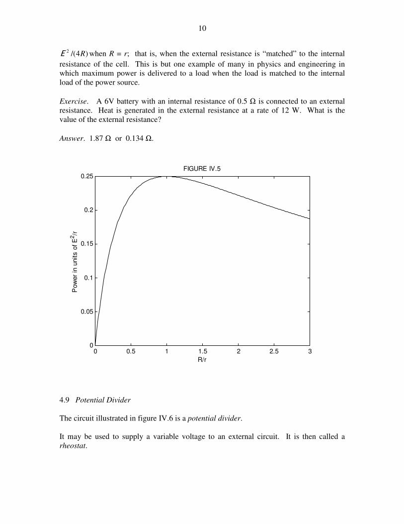
In figure IV.5 I have plotted the power (in units of E 2
/R) versus R/r. Differentiation of
the above expression (do it!) will show that the power delivered reaches a maximum of
• • A
FIGURE IV.4
B R I E r
10
)4/(2 RE when R = r; that is, when the external resistance is “matched” to the internal
resistance of the cell. This is but one example of many in physics and engineering in
which maximum power is delivered to a load when the load is matched to the internal
load of the power source.
Exercise. A 6V battery with an internal resistance of 0.5 Ω is connected to an external
resistance. Heat is generated in the external resistance at a rate of 12 W. What is the
value of the external resistance?
Answer. 1.87 Ω or 0.134 Ω.
0 0.5 1 1.5 2 2.5 30
0.05
0.1
0.15
0.2
0.25
R/r
Pow
er
in u
nits o
f E
2/r
FIGURE IV.5
4.9 Potential Divider
The circuit illustrated in figure IV.6 is a potential divider.
It may be used to supply a variable voltage to an external circuit. It is then called a
rheostat.

11
Or it may be used to compare potential differences, in which case it is called a
potentiometer. (In practice many people refer to such a device as a “pot”, regardless of
the use to which it is put.)
For example, in figure IV.7, a balance point (no current in the ammeter, A) is found when
the potential drop down the length x of the resistance wire is equal to the EMF of the
small cell. (Note that, since no current is being taken from the small cell, the potential
difference across its poles is indeed the EMF.) One could compare the EMFs of two cells
in this manner, one of which might be a “standard cell” whose EMF is known.
In figure IV.8, a current is flowing through a resistor (which is assumed to be in part of
some external circuit, not drawn), and, assuming that the potential gradient down the
potentiometer has been calibrated with a standard cell, the potentiometer is being used to
measure the potential difference across the resistor. That is, the potentiometer is being
used as a voltmeter.
• •
FIGURE IV.6
• •
FIGURE IV.7
A
x

12
4.10 Ammeters and Voltmeters
For the purpose of this section it doesn’t matter how an ammeter actually works. Suffice
it to say that a current flows through the ammeter and a needle moves over a scale to
indicate the current, or else the current is indicated as numbers in a digital display. In
order to measure the current through some element of a circuit, the ammeter is placed, of
course, in series with the element. Generally an ammeter has rather a low resistance.
An inexpensive voltmeter is really just an ammeter having rather a high resistance. If you
want to measure the potential difference across some circuit element, you place the
voltmeter, of course, across that element (i.e. in parallel with it). A small portion of the
current through the element is diverted through the meter; the meter measures this
current, and, from the known resistance of the meter, the potential difference can be
calculated – though in practice nobody does any calculation – the scale is marked in
volts. Placing a meter across a circuit element in fact slightly reduces the potential
difference across the element – that is, it reduces the very thing you want to measure.
But, because a voltmeter typically has a high resistance, this effect is small. There are, of
course, modern (and more expensive) voltmeters of a quite different design, which take
no current at all, and genuinely measure potential difference, but we are concerned in this
section with the commonly-encountered ammeter-turned-voltmeter. It may be noticed
that the potentiometer described in the previous section takes no current from the circuit
element of interest, and is therefore a true voltmeter.
There are meters known as “multimeters” or “avometers” (for amps, volts and ohms),
which can be used as ammeters or as voltmeters, and it is with these that this section is
concerned.
A typical inexpensive ammeter gives a full scale deflection (FSD) when a current of 15
mA = 0.015 A flows through it. It can be adapted to measure higher currents by
connecting a small resistance (known as a “shunt”) across it.
• •
FIGURE IV.8
A

13
Let’s suppose, for example, that we have a meter that which shows a FSD when a current
of 0.015 A flows through it, and that the resistance of the meter is 10 Ω. We would like
to use the meter to measure currents as high as 0.15 A. What value of shunt resistance
shall we put across the meter? Well, when the total current is 0.15 A, we want 0.015 A to
flow through the meter (which then shows FSD) and the remainder, 0.135 A, is to flow
through the shunt. With a current of 0.015 A flowing through the 10 Ω meter, the
potential difference across it is 0.15 V. This is also the potential difference across the
shunt, and, since the current through the shunt is 0.135 A, the resistance of the shunt must
be 1.11 Ω.
We can also use the meter as a voltmeter. Suppose, for example, that we want to measure
voltages (horrible word!) of up to 1.5 V. We place a large resistance R in series with the
meter, and then place the meter-plus-series-resistance across the potential difference to
measured. The total resistance of meter-plus-series-resistance is (10 + R), and it will
show a FSD when the current through it is 0.015 A. We want this to happen when the
potential difference across it is 1.5 volts. This 1.5 = 0.015 × (10 + R), and so R = 90
Ω.
4.11 Wheatstone Bridge
G
R1 R2
R3 R4
FIGURE IV.9

14
The Wheatstone bridge can be used to compare the value of two resistances – or, if the
unknown resistance is compared with a resistance whose value is known, it can be used
to measure an unknown resistance. R1 and R2 can be varied. R3 is a standard resistance
whose value is known. R4 is the unknown resistance whose value is to be determined. G
is a galvanometer. This is just a sensitive ammeter, in which the zero-current position
has the needle in the middle of the scale; the needle may move one way or the other,
depending on which way the current is flowing. The function of the galvanometer is not
so much to measure current, but merely to detect whether or not a current is flowing in
one direction of another. In use, the resistances R1 and R2 are varied until no current
flows in the galvanometer. The bridge is then said to be “balanced” and
,// 4321 RRRR = and hence the unknown resistance is given by ./ 2314 RRRR =
4.12 Delta-Star Transform
Consider the two circuits (each enclosed in a black box) of figure IV.10.
The configuration in the left hand box is called a “delta” (∆) and the configuration in the
right hand box is called a “star” or a “Y”. I have marked against each resistor its
resistance and its conductance, the conductance, of course, merely being the reciprocal of
the resistance. I am going to suppose that the resistance between the terminals X and Y is
the same for each box. In that case:
.)(
321
21321
RRR
RRRrr
++
+=+ 4.12.1
We can get similar equations for the terminal pairs Y,Z and Z,X. Solving the three
equations for r1 , r2 and r3, we obtain
X
Z
R1 , G1
R3 , G3
R2 , G2
• •
•
Y X
Z
• •
•
Y
r1 , g1 r2 , g2
r3 , g3
FIGURE IV.10
15
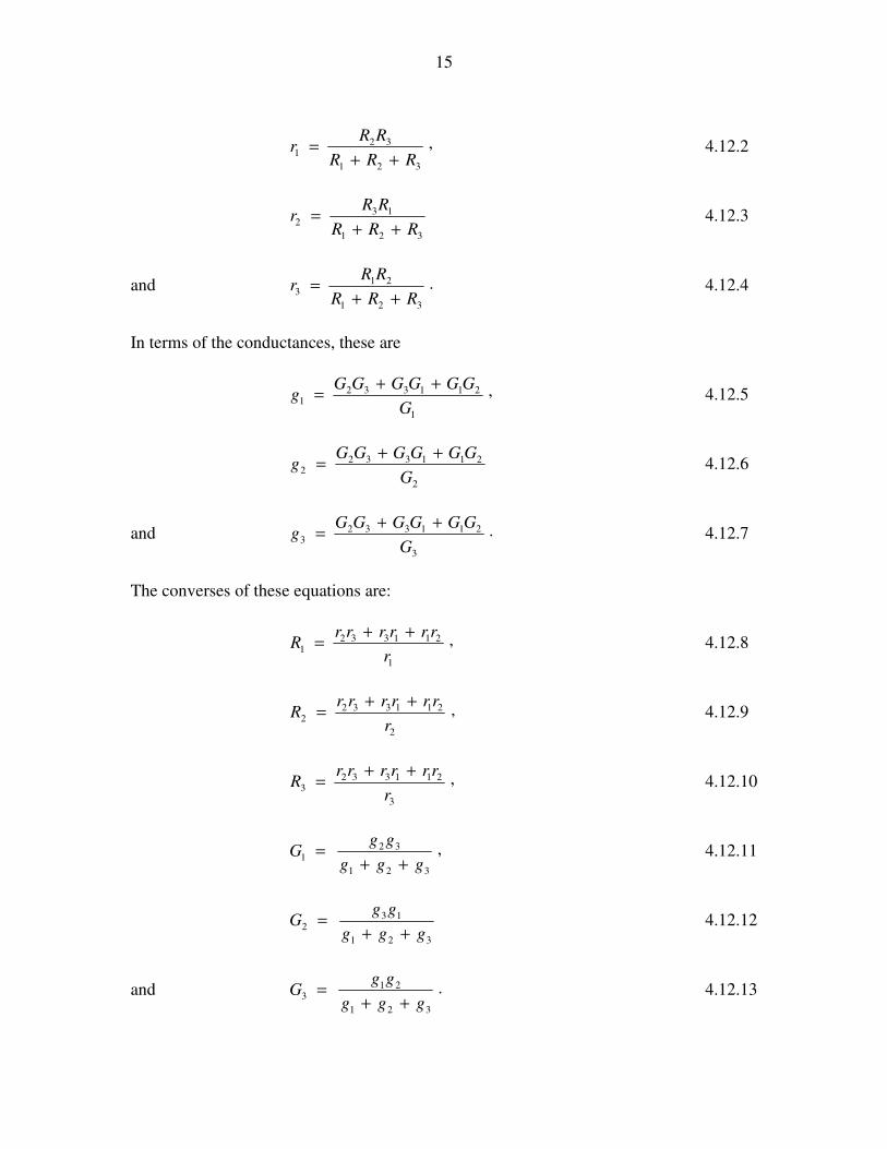
,
321
321
RRR
RRr
++= 4.12.2
321
132
RRR
RRr
++= 4.12.3
and .321
213
RRR
RRr
++= 4.12.4
In terms of the conductances, these are
,
1
2113321
G
GGGGGGg
++= 4.12.5
2
2113322
G
GGGGGGg
++= 4.12.6
and .
3
2113323
G
GGGGGGg
++= 4.12.7
The converses of these equations are:
,
1
2113321
r
rrrrrrR
++= 4.12.8
,
2
2113322
r
rrrrrrR
++= 4.12.9
,
3
2113323
r
rrrrrrR
++= 4.12.10
,321
321
ggg
ggG
++= 4.12.11
321
132
ggg
ggG
++= 4.12.12
and .321
213
ggg
ggG
++= 4.12.13

16
That means that, if the resistances and conductances in one box are related to the
resistances and conductances in the other by these equations, then you would not be able
to tell, if you had an ammeter, and a voltmeter and an ohmmeter, which circuit was in
which box. The two boxes are indistinguishable from their electrical behaviour.
These equations are not easy to commit to memory unless you are using them every day,
and they are sufficiently awkward that mistakes are likely when evaluating them
numerically. Therefore, to make the formulas useful, you should programme your
calculator or computer so that they will instantly convert between delta and star without
your ever having to think about it. The next example shows the formulas in use. It will
be heavy work unless you have programmed your computer in advance – but if you have
done so, you will see how very useful the transformations are.
Example. Calculate the resistance between the points A and B in the figure below. The
individual resistances are given in ohms.
At first, one doesn’t know how to start. But notice that the 1, 3 and 4 ohm resistors are
connected in delta and the circuit is therefore equivalent to
After that, it is easy, and you will soon find that the resistance between A and B is 2.85
Ω.
4.13 Kirchhoff’s Rules
There are two h’s in his name, and there is no tch sound in the middle. The pronunciation
is approximately keerr–hhofe.
1 8
• •
3
4
2
A B
8
•
2
B •
A 0.375 1.5
0.5

17
The rules themselves are simple and are self-evident. What has to be learned, however, is
the art of using them.
K1: The net current going into any point in a circuit is zero; expressed otherwise, the
sum of all the currents entering any point in a circuit is equal to the sum of all the
currents leaving the point.
K2: The sum of all the EMFs and IR products in a closed circuit is zero. Expressed
otherwise, as you move around a closed circuit, the potential will sometimes rise and
sometimes fall as you encounter a battery or a resistance; but, when you come round
again to the point where you started, there is no change in potential.
Example.
In the above circuit, the 24 V battery is assumed to have negligible internal resistance.
Calculate the current in each of the resistors.
The art of applying Kirchhoff’s rules is as follows.
1. Draw a large circuit diagram in pencil.
2. Count the number of independent resistors. (Two is series with nothing in between
don’t count as independent.) This tells you how many independent equations you can
obtain, and how many unknowns you can solve for. In this case, there are five
independent resistors; you can get five independent equations and you can solve for five
unknowns.
3. Mark in the unknown currents. If you don’t know the directions of some of them,
don’t spend time trying to think it out. Just make a wild guess. If you are wrong, you
will merely get a negative answer for it. Those who have some physical insight might
already guess (correctly) that I have marked I5 in the wrong direction, but that doesn’t
matter.
1 8
• •
3
4
2
A B
24 V
I4
I5
Ω
I1
I2
I3 Ω
Ω
Ω
Ω
C
D
O

18
4. Choose any closed circuit and apply K2. Go over that closed surface in ink. Repeat
for several closed circuits until the entire diagram is inked over. When this happens, you
cannot get any further independent equations using K2. If you try to do so, you will
merely end up with another equation that is a linear combination of the ones you already
have,
5. Make up the required number of equations with K1.
Let us apply these to the present problem. There are five resistors; we need five
equations. Apply K2 to OACBO. Start at the negative pole of the battery and move
counterclockwise around the circuit. When we move up to the positive pole, the potential
has gone up by 24 V. When we move down a resistor in the direction of the current, the
potential goes down. For the circuit OACBO, K2 results in
.02324 31 =−− II
Now do the same this with circuit OADBO:
,0824 42 =−− II
and with circuit ACDA:
.043 251 =−+ III
If you have conscientiously inked over each circuit as you have done this, you will now
find that the entire diagram is inked over. You cannot gain any further independent
equations from K2. We need two more equations. Apply K1 to point C:
,531 III +=
and to point D: .524 III +=
You now have five independent linear equations in five unknowns and you can solve
them. (Methods for solving simultaneous linear equations are given in Chapter 1, Section
1.7 of Celestial Mechanics.) The solutions are:
.A927.1,A453.2,A956.5,A380.4,A029.4 54321 −=+=+=+=+= IIIII
4.14 Tortures for the Brain
I don’t know if any of the examples in this section have any practical applications, but
they are excellent ways for torturing students, or for whiling away rainy Sunday
afternoons.

19
4.14.1
The drawing shows 12 resistances, each of value r Ω, arranged along the edges of a cube.
What is the resistance across opposite corners of the cube?
4.14.2
12 V
A
B

20
The drawing shows six resistors, each of resistance 1 Ω, arranged along the edges of a
tetrahedron. A 12 V battery is connected across one of the resistors. Calculate the
current between points A and B.
4.14.3
The figure shows six resistors, whose resistances in ohms are marked, arranged along the
edges of a tetrahedron. Calculate the net resistance between C and D.
4.14.4 R1 = 8 Ω and R2 = 0.5 Ω are connected across a battery. The rate at which
heat is generated is the same whether they are connected in series or in parallel. What is
the internal resistance r of the battery?
4.14.5 R1 = 0.25 Ω and R2 = ? are connected across a battery whose internal
resistance r is 0.5 Ω. The rate at which heat is generated is the same whether they are
connected in series or in parallel. What is the value of R2?
6
2
12 4
3
D C
5

21
4.14.6
In the above circuit, each resistance is 1 ohm. What is the net resistance between A and
B if the chain is of infinite length?
4.14.7 What is the resistance between A and B in question 4.14.6 if the chain is not of
infinite length, but has n “links” – i.e. 2n resistors in all?
4.14.8
In the circuit below, what is the potential difference between A and B, and what is the
current in each resistor?
4.14.9 What is the net resistance between A and D? -
A
B
6 V 12 V 4 V
2 Ω 3 Ω 2 Ω
A
B
3 Ω
4 Ω
2 Ω
6 Ω
5 Ω
A
B
C
D

22
4.15 Solutions, Answers or Hints to 4.14
Hints for 4.14.1. Imagine a current of 6I going into the bottom left hand corner.
Follow the current through the cube, writing down the current through each of the 12
resistors. Also write down the potential drop across each resistor, and hence the total
potential drop across the cube. I make the answer for the effective resistance of the
whole cube .65 r
Solution for 4.14.2. By symmetry, the potentials of A and B are equal. Therefore
there is no current between A and B.
Hint for 4.14.3. Replace the heavily-drawn delta with its corresponding star. After
that it should be straightforward, although there is a little bit of calculation to do. I make
the answer 1.52 Ω .
Solution for 4.14. From equation 4.8.1, the rate at which heat is generated in a
resistance R connected across a battery of EMF E and internal resistance r is .)( 2
2
rR
R
+
E
If the resistors are connected in series, ,21 RRR += while if they are connected in
parallel, .
21
21
RR
RRR
+= If the heat generated is the same in either case, we must have
.)(
2
21
21
21
21
2
21
21
+
+
+=
++
+
rRR
RR
RR
RR
rRR
RR
After some algebra, we obtain
.
11
2
2
1
2121
−+
−+=
R
R
R
R
RRRRr 4.15.1
With R1 = 8 Ω and R2 = 0.5 Ω, we obtain r = 2.00 Ω .

23
Solution for 4.14.5.
In equation 4.15.1, let .and1
2
1
xR
Ra
R
r== The equation 4.15.1 becomes
.1)/1(
1 2
−+
−+=
xx
xxa 4.15.2
Upon rearrangement, this is
.0)1()1( 32 =−+++− xxaxaa 4.15.3
In our example, ,225.0
50.0
1
===R
ra so that equation 4.15.4 is
,0332 32 =−+− xxx
or .0)1)(2( 2 =+−− xxx
The only real root is x = 2. But .125.0 22
12 Ω=== xxRR
Solution to 4.14.6 Suppose that there are n links (2n resistors) to the right of the
dotted line, and that the effective resistance of these n links is Rn. Add one more link, to
the left. The effective resistance of the n + 1 links is then
.1
121
+
+=+
n
nn
R
RR 4.15.4
As ., 1 RRRn nn →→∞→ + .01or,1
12 2 =−−+
+=∴ RR
R
RR
Whence, .989033618.1)15(21 Ω=+=R
Solution to 4.14.7 By repeated application of equation 4.15.4, we find:

24
989033618.112
990033618.111
999033618.110
056034618.19
448034618.18
135037618.17
556055618.16
818181618.15
619047619.14
000000625.13
667666666.12
21
4636875025
1771128657
676510946
25844181
9871597
377610
144233
5589
2134
813
35
=
=
=
=
=
=
=
=
=
=
=
nRn
Inspection shows that ,
2
12
n
n
nF
FR
+= where Fm is the mth member of the Fibonacci
sequence: 1 1 2 3 5 8 13 21 ......
But, from the theory of Fibonacci sequences,
.2
51
2
51
5
1
−−
+=
mm
mF
Hence Ω
−−+
−−+=
++
nn
nn
nR22
1212
)51()51(
)51()51(
2
1
Solution to 4.14.8
6 V 12 V 4 V
2 Ω 3 Ω 2 Ω
A I1 I2
I3
B

25
I’ll call the potential at B (and at the negative poles of each cell) zero, which is
equivalent to grounding (earthing) the point B; and I’ll call the potential at A V.
I don’t think all of the currents will be in the direction indicated on the drawing. One or
more must be in the other direction, and one or more of the cells are being re-charged. I
don’t know which is wrong, so I’ll just leave them as drawn for the time being, and we’ll
see what happens. Apply Ohm’s law to each resistor in turn:
2
4;
3
12;
2
6321
−=
−=
−=
VI
VI
VI amps, and apply Kirchhoff’s first rule to
A: .0321 =++ III From these, we obtain V = 6.750 V, I1 = 0.375 A, I2 = −1.75 A,
I2 = 1.375 A.
Solution to 4.14.9
Let us start by re-drawing the circuit. Numbers are the resistances in ohms.
We have a star (3,4,2), which can be transformed to a delta; and
we have a delta (3,2,5), which can be transformed to a star.
I elect to convert the delta to a star. You could try the other way and see how it goes.
I use my computer program which instantly does the delta-star transformation.
5
3 2
4
6 A
B
C D

26
Re-draw:
Very soon after that I arrive at R = 21.78 Ω
4.16 Attenuators
These are networks, usually of resistors, that serve the dual purpose of supplying more
examples for students or for reducing the voltage, current or power from one circuit to
another. An example of the former might be:
4
6 A
B
C D
3.10 &
6.2
15.5
M
15.5
10.2
3.16 &
A M D

27
You might be told the values of the four left-hand resistances and of the EMF of the cell,
and you are asked to find the current in the right hand resistor.
On the other hand, if the object is to design an attenuator, you might be told the values of
the resistances at the two ends, and you are required to find the resistances of the three
middle resistors such that the current in the rightmost resistor is half the current in the left
hand resistor. The three intermediate resistances perform the function of an attenuator.
In the drawing below, A is some sort of a device, or electrical circuit, or, in the simplest
case, just a battery, which has an electromotive force E and an internal resistance RA. C
is some other device, whose internal resistance is RC. B is an attenuator, which is a
collection of resistors which you want to design so that the current delivered to C is a
certain fraction of the current flowing from A; or so that the voltage delivered across the
terminals of C is a certain fraction of the voltage across the terminals of A; or perhaps
again so that the power delivered to C is a certain fraction of the power generated by A.
The circuit in the attenuator has to be designed so as to achieve one of these goals.
Four simple attenuators are known as T, H, ΠΠΠΠ or square, named after their shapes. In
the drawing below, the H is on its side, like this:
A
E RA
C
RC
B
H

28
Let us look at a T attenuator. We’ll suppose that the A device has an electromotive force
E and an internal resistance R, and indeed it can be represented by a cell in series with a
resistor. And we’ll suppose that the resistance of the C device is also R and it can be
represented by a single resistor. We’ll suppose that we want the current that flows into C
to be a fraction a of the current flowing out of A, and the voltage to be supplied to C to
be a fraction a of the potential difference across the output terminals of A. What must be
the values of the resistances in the T attenuator? I’ll call them r1R and r2R, so that we
have to determine the dimensionless ratios r1 and r2. The equivalent circuit is:
R1 R1
R2
T
R1 R1
R2
H
R1 R1
R1
R2
ΠΠΠΠ
R2
R1
R2 R2
R1
E
R
R
r1R
r2R
r1R
aI Ia)1( − I
A
B
C
D
E
F
29
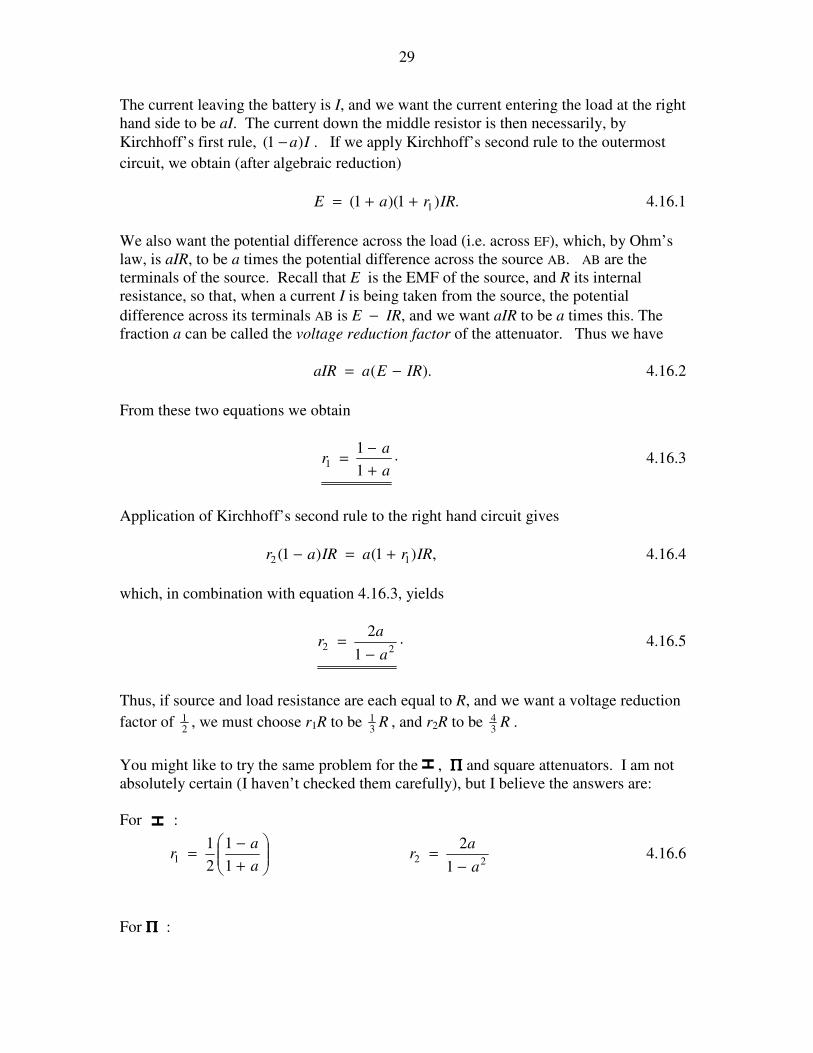
The current leaving the battery is I, and we want the current entering the load at the right
hand side to be aI. The current down the middle resistor is then necessarily, by
Kirchhoff’s first rule, Ia)1( − . If we apply Kirchhoff’s second rule to the outermost
circuit, we obtain (after algebraic reduction)
.)1)(1( 1 IRraE ++= 4.16.1
We also want the potential difference across the load (i.e. across EF), which, by Ohm’s
law, is aIR, to be a times the potential difference across the source AB. AB are the
terminals of the source. Recall that E is the EMF of the source, and R its internal
resistance, so that, when a current I is being taken from the source, the potential
difference across its terminals AB is E − IR, and we want aIR to be a times this. The
fraction a can be called the voltage reduction factor of the attenuator. Thus we have
).( IREaaIR −= 4.16.2
From these two equations we obtain
.1
11
a
ar
+
−= 4.16.3
Application of Kirchhoff’s second rule to the right hand circuit gives
,)1()1( 12 IRraIRar +=− 4.16.4
which, in combination with equation 4.16.3, yields
.1
222
a
ar
−= 4.16.5
Thus, if source and load resistance are each equal to R, and we want a voltage reduction
factor of 21 , we must choose r1R to be R
31 , and r2R to be R
34 .
You might like to try the same problem for the , ΠΠΠΠ and square attenuators. I am not
absolutely certain (I haven’t checked them carefully), but I believe the answers are:
For :
+
−=
a
ar
1
1
2
11
221
2
a
ar
−= 4.16.6
For Π Π Π Π :
H
H

30
a
ar
2
1 2
1
−=
a
ar
−
+=
1
12 4.16.7
For square :
−=
a
ar
2
1
2
1 2
1 a
ar
−
+=
1
12 4.16.7