chapter 4 cache memoryrahimi/cs401/slides/sh-chap4.pdfcache read operation • cpu requests contents...
TRANSCRIPT

Chapter 4Cache Memory

Contents• Computer memory system overview
—Characteristics of memory systems—Memory hierarchy
• Cache memory principles• Elements of cache design
—Cache size—Mapping function—Replacement algorithms—Write policy—Line size—Number of caches
• Pentium 4 and PowerPC cache organizations

Key Points• Memory hierarchy
—processor registers—cache—main memory—fixed hard disk—ZIP cartridges, optical disks, and tape
• Going down the hierarchy—decreasing cost, increasing capacity, and slower
access time
• Principles of locality—during the execution of a program, memory
references tend to cluster

4.1 Computer Memory System Overview• Characteristics of memory systems
—Location—Capacity—Unit of transfer—Access method—Performance—Physical type—Physical characteristics
– volatile/nonvolatile– erasable/nonerasable
—Organization
Location• CPU• Internal
—main memory—cache
• External(secondary)—peripheral storage devices—disk, tape

Capacity• Word size
—natural unit of organization—8, 16, 32, and 64 bits
• Number of words—memory capacity

Unit of Transfer
• Internal memory—Usually governed by data bus width
• External memory—Usually a block which is much larger than a word

Access Methods (1)
• Sequential—Start at the beginning and read through in order—Access time depends on location of data and previous
location—e.g. tape
• Direct—Individual blocks have unique address—Access is by jumping to vicinity plus sequential
search—Access time depends on location of data and previous
location—e.g. disk
Access Methods (2)
• Random—Each location has a unique address—Access time is independent of location or previous
access—e.g. RAM
• Associative—Data is retrieved based on a portion of its contents
rather than its address—Access time is independent of location or previous
access—e.g. cache

Performance• Access time (latency)
—For random-access memory– time between presenting the address and getting the valid
data
—For non-random-access memory– time to position the read-write head at the location
• Memory Cycle time (primarily applied to random-access memory) —Time may be required for the memory to “recover”
before next access– die out on signal lines– regenerate data if they are read destructively
—access time + recover time
• Transfer Rate—For random-access memory, equal to 1/(cycle time)

Performance• For non-random-access memory, the following
relationship holds:
TN = TA + N/R
whereTN = Average time to read or write N bitsTA = Average access timeN = Number of bitsR = Transfer rate, in bits per second(bps)
Physical Types• Semiconductor
—RAM, ROM
• Magnetic—Disk, Tape
• Optical—CD, CD-R, CD-RW, DVD

Physical Characteristics• Volatile/Nonvolatile• Erasable/Nonerasable

Questions on Memory Design• How much?
—Capacity
• How fast?—Time is money
• How expensive?

Hierarchy List• Registers• L1 Cache• L2 Cache• Main memory• Disk cache• Disk• Optical• Tape

Memory Hierarchy - Diagram

As Going Down The Hierarchy• Decreasing cost per bit• Increasing capacity• Increasing access time• Decreasing frequency of access of memory by
the processor

An Example• Suppose we have two levels of memory
—L1 : 1000 words, 0.01 us access time—L2 : 100,000 words, 0.1 us access time—H = fraction of all memory accesses found in L1—T1 = access time to L1—T2 = access time to L2
• Suppose H = 0.95—(0.95)(0.01 us) + (0.05)(0.01 us + 0.1 us)
= 0.095 + 0.0055 = 0.015 us—average access time is much closer to 0.01 us


Principle of Locality• As going down the hierarchy, we had the
decreasing frequency of access by the processor—this is possible due to the principle of locality
• During the course of the execution of a program, memory references tend to cluster—programs contain loops and procedures
– there are repeated references to a small set of instructions
—operations on arrays involve access to a clustered set of data
– there are repeated references to a small set of data

4.2 Cache Memory Principles• Cache
—Small amount of fast memory local to processor—Sits between main memory and CPU

Cache/Main Memory Structure

Cache Read Operation• CPU requests contents of memory location• Check cache for this data• If present, get from cache (fast)• If not present, read required block from main
memory to cache• Then deliver from cache to CPU• Cache includes tags to identify which block of
main memory is in each cache slot

Cache Read Operation
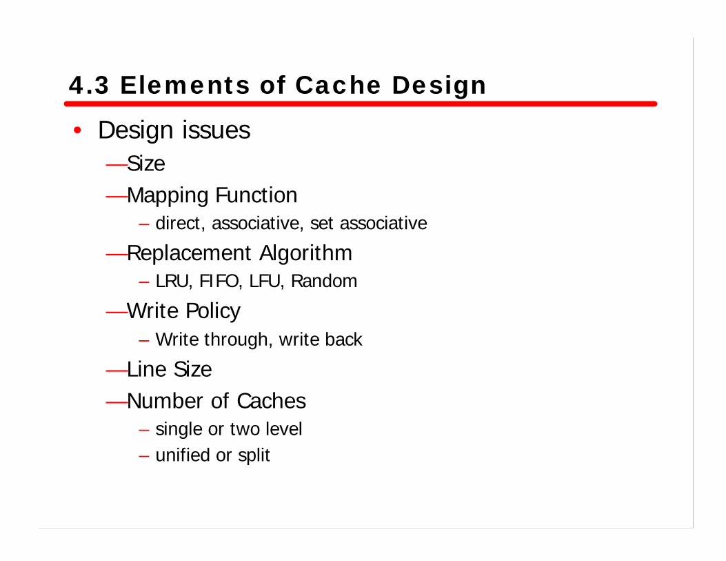
4.3 Elements of Cache Design• Design issues
—Size—Mapping Function
– direct, associative, set associative
—Replacement Algorithm– LRU, FIFO, LFU, Random
—Write Policy– Write through, write back
—Line Size—Number of Caches
– single or two level– unified or split

Size Does Matter• Small enough to make it cost effective• Large enough for performance reasons
—but larger caches tend to be slightly slower than small ones

Mapping Function• Fewer cache lines than main memory blocks
—mapping is needed—also need to know which memory block is in cache
• Techniques—Direct—Associative—Set associative
• Example case—Cache size : 64 KByte—Line size : 4 Bytes
– cache is organized as 16 K lines
—Main memory size : 16 Mbytes– each byte is directly addressable by a 24-bit address

Direct Mapping• Maps each block into a possible cache line• Mapping function
i = j modulo mwhere
i = cache line numberj = main memory block numberm = number of lines in the cache
• Address is in three parts—Least Significant w bits identify unique word—Most Significant s bits specify one memory block
– these are split into a cache line field r and a tag s-r(most significant)

Direct Mapping - Address Structure• Address length = (s + w) bits• Number of addressable units = 2s+w words or bytes• Block size = line size = 2w words or bytes• Number of blocks in main memory = 2s+ w/2w = 2s
• Number of lines in cache = m = 2r
• Size of tag = (s – r) bits
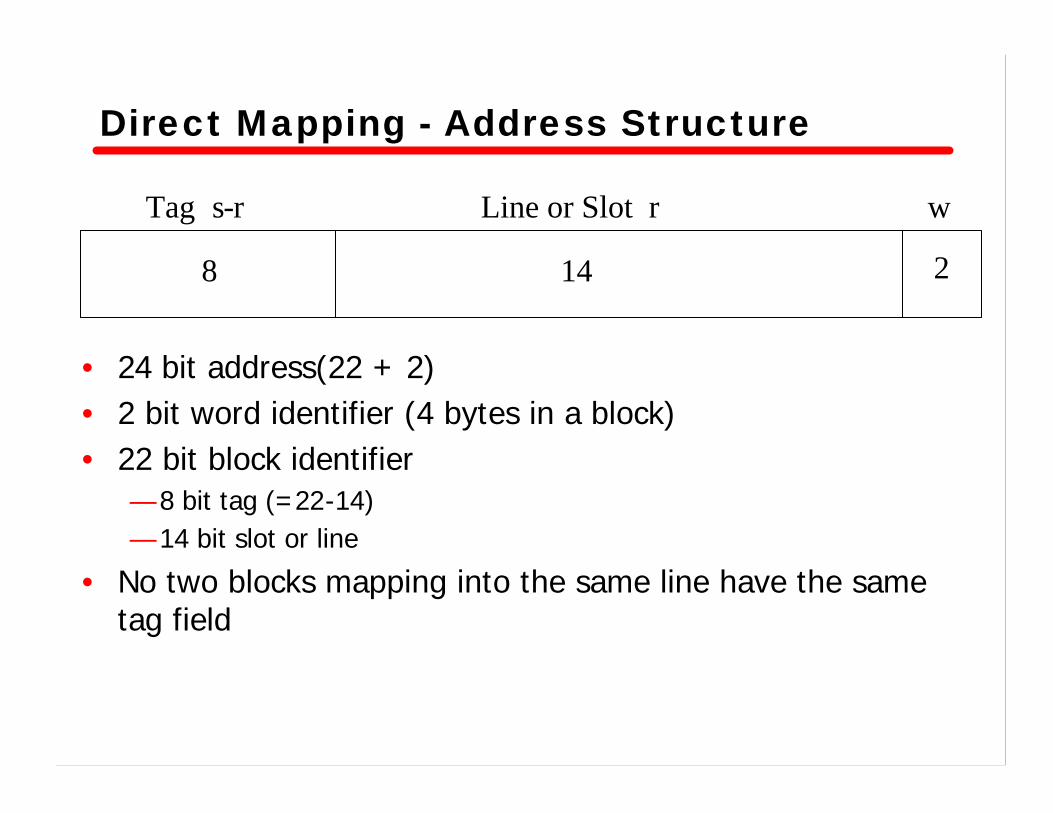
Direct Mapping - Address Structure
Tag s-r Line or Slot r w
8 14 2
• 24 bit address(22 + 2)• 2 bit word identifier (4 bytes in a block)• 22 bit block identifier
— 8 bit tag (=22-14)— 14 bit slot or line
• No two blocks mapping into the same line have the same tag field
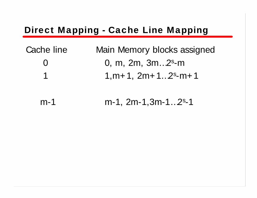
Direct Mapping - Cache Line Mapping
Cache line Main Memory blocks assigned0 0, m, 2m, 3m…2s-m1 1,m+1, 2m+1…2s-m+1
m-1 m-1, 2m-1,3m-1…2s-1

Direct Mapping - Cache Line Mapping
Cache line Starting memory address of block0 000000, 010000,…, FF00001 000004, 010004,…, FF0004
m-1 00FFFC, 01FFFC,…, FFFFFC
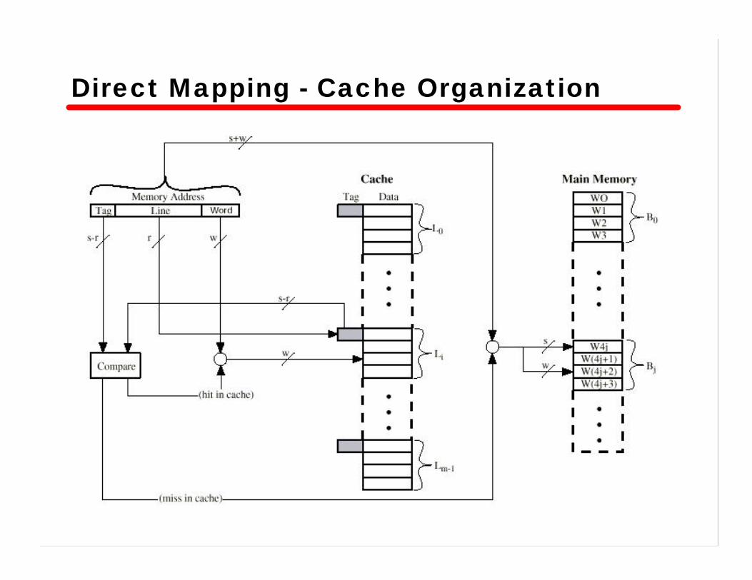
Direct Mapping - Cache Organization
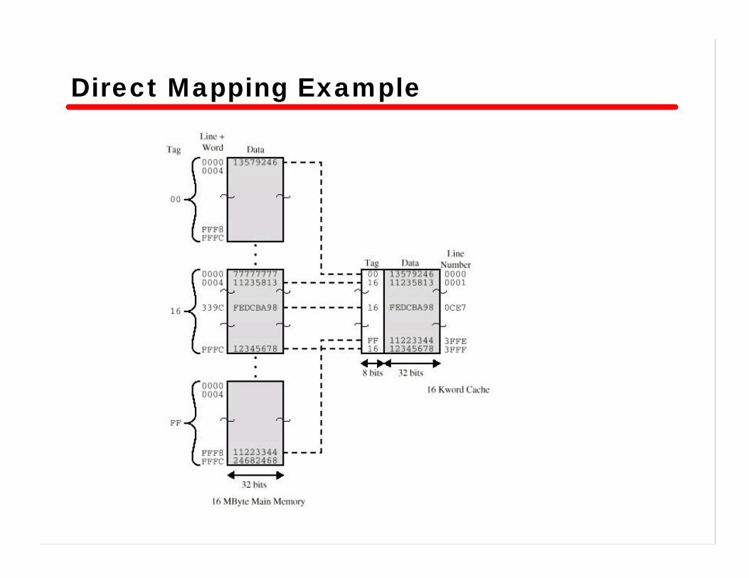
Direct Mapping Example

Direct Mapping Pros & Cons• Simple and inexpensive to implement• Fixed cache location for any given block
—If a program accesses 2 blocks that map to the same line repeatedly, cache misses are very high

Associative Mapping• A main memory block can be loaded into any
line of cache• Memory address is interpreted as a tag and a
word field—Tag field uniquely identifies a block of memory
• Every line’s tag is simultaneously examined for a match—Cache searching gets complex and expensive

Associative Mapping - Address Structure• Address length = (s + w) bits• Number of addressable units = 2s+w words or bytes• Block size = line size = 2w words or bytes• Number of blocks in main memory = 2s+ w/2w = 2s
• Number of lines in cache = cannot specify using s or w• Size of tag = s bits

Tag 22 bitWord2 bit
Associative Mapping - Address Structure
• 22 bit tag stored with each 32 bit block of data• Compare tag field with tag entry in cache to
check for hit• Least significant 2 bits of address identify which
byte is required from 32 bit data block

Fully Associative Cache Organization

Associative Mapping - Example

Associative Mapping Pros & Cons• Flexible as to which block to replace when a
new block is read into the cache—need to select one which is not going to be used in
the near future
• Complex circuitry is required to examine the tags of all cache lines

Set Associative Mapping• A compromise of direct and associative methods• Cache is divided into a number of sets(v)• Each set contains a number of lines(k)• The relationships are
m = v x ki = j modulo v
wherei = cache set numberj = main memory block numberm = number of lines in the cache

Set Associative Mapping - Address• Address length = (s + w) bits• Number of addressable units = 2s+w words or bytes• Block size = line size = 2w words or bytes• Number of blocks in main memory = 2s+ w/2w = 2s
• Number of lines in set = k• Number of sets = v = 2d
• Number of lines in cache = kv = k * 2d
• Size of tag = (s – d) bits• Address is interpreted as 3 fields
— tag, set, and word

Set Associative Mapping - Address
• Use set field to determine cache set to look in—this determines the mapping of blocks into lines
• Compare tag field to see if we have a hit—two lines are examined simultaneously
• If v = m, k = 1, same as direct mapping• If v = 1, k = m, same as associative mapping• two- or four-way set associative mappings are
common
Tag 9 bit Set 13 bitWord2 bit
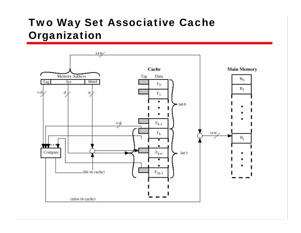
Two Way Set Associative Cache Organization

Two Way Set Associative Mapping -Example

Replacement Algorithms• When a new block is brought into cache, one of
the existing blocks must be replaced• Direct mapping
—Only one possible line for any particular block– No choice– Replace that line
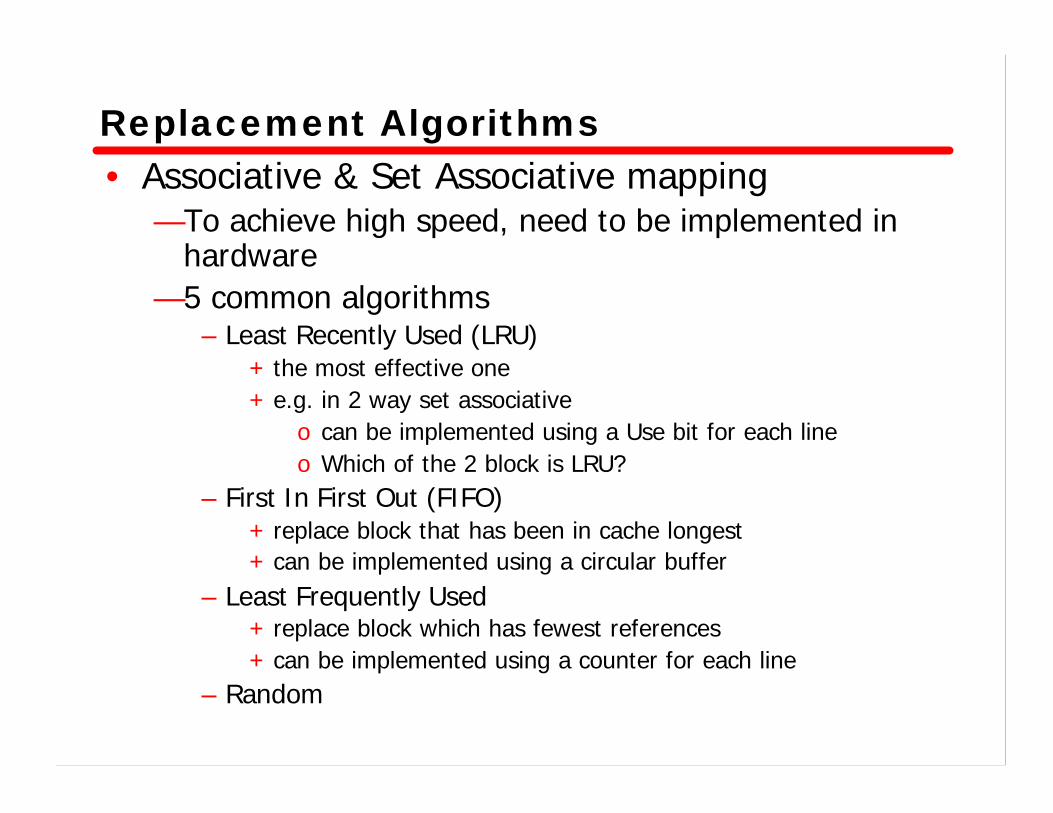
Replacement Algorithms• Associative & Set Associative mapping
—To achieve high speed, need to be implemented in hardware
—5 common algorithms– Least Recently Used (LRU)
+ the most effective one+ e.g. in 2 way set associative
o can be implemented using a Use bit for each lineo Which of the 2 block is LRU?
– First In First Out (FIFO)+ replace block that has been in cache longest+ can be implemented using a circular buffer
– Least Frequently Used+ replace block which has fewest references+ can be implemented using a counter for each line
– Random

Replacement Algorithms
– Clock algorithm+ upgraded version of FIFO+ Additional bit called a use bit+ When a block is first loaded in cache, use bit is set to 1+ When the block is referenced, use bit is set to 1+ When it is time to replace a block, the first block encountered
with the use bit set to 0 is replaced+ During the search for replacement, each use bit with 1 is
changed to 0

Example of clock policy operation

Example of clock policy operation

Write Policy• When a block in the cache is to be replaced,
need to consider whether it has been altered—If not, that block may be overwritten—If so, main memory need to be updated
• Two problems to contend—More than one device may have access to main
memory—Multiple processors with their own caches
• Two techniques—Write through—Write back

Write through• All writes go to main memory as well as cache• Other CPUs can monitor main memory traffic to
keep their cache up to date• Disadvantage
—generates substantial memory traffic

Write back• Updates are made only in cache
—Update bit for cache line is set—If a block is to be replaced, write to main memory
only if update bit is set
• Portions of main memory may be invalid—accesses by other devices are allowed only through
the cache
• Experiences—15% of memory references are writes—For HPC, 33~50% are writes

Cache Coherency• Cache coherency in shared memory multiprocessors
—Bus watching with write through– each cache controller monitors the address lines– if another master writes to a location that also resides in its
cache, cache entry is invalidated
—Hardware transparency– all updates to main memory are reflected in all caches
—Noncacheable memory– only a portion of memory is shared by processors– this is designated as noncacheable– this portion is never copied into the cache

Line Size• Effects of line size
—Larger blocks means a small number of blocks– there will be more replacements– data will be overwritten shortly after they are fetched
—As a block becomes larger, each additional word is farther from the requested word, and less likely to be needed in the near future
– principle of locality does not apply well
• 8 to 32 bytes sizes are close to optimum• For HPC, 64 to 128 bytes sizes are common

Number of Caches• Multilevel caches
—On-chip cache– speeds up execution and increases performance
—Is off-chip cache still desirable?– the speed gap between CPU and main memory is too big– most designs include both caches– usually called L1 and L2 caches
• Unified vs. Split caches—trend is toward split caches
– one cache each for instruction and data– eliminate the contention for the cache between instruction
fetch/decode unit and execution unit
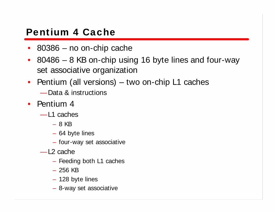
Pentium 4 Cache• 80386 – no on-chip cache• 80486 – 8 KB on-chip using 16 byte lines and four-way
set associative organization• Pentium (all versions) – two on-chip L1 caches
— Data & instructions
• Pentium 4 — L1 caches
– 8 KB– 64 byte lines– four-way set associative
— L2 cache – Feeding both L1 caches– 256 KB– 128 byte lines– 8-way set associative
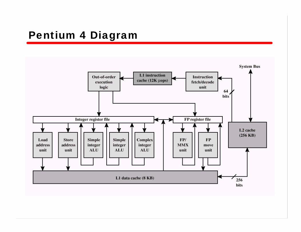
Pentium 4 Diagram

Pentium 4 Processor Core• Fetch/Decode Unit
— Fetches instructions from L2 cache— Decode into micro-ops— Store micro-ops in L1 cache
• Out of order execution logic— Schedules micro-ops— Based on data dependencies and resources— May speculatively execute
• Execution units— Execute micro-ops— Data from L1 cache— Results in registers
• Memory subsystem— L2 cache and systems bus

Pentium 4 Design Reasoning
• Decodes instructions into RISC like micro-ops before L1 cache
• Micro-ops fixed length— Superscalar pipelining and scheduling
• Pentium instructions long & complex• Performance improved by separating decoding from
scheduling & pipelining— (More later – ch14)
• Data cache is write back— Can be configured to write through

Power PC Cache Organization• 601 – single 32 KB 8-way set associative• 603 – 16 KB (2 x 8 KB) 2-way set associative• 604 – 32 KB (2 x 8 KB) 4-way set associative• 620 – 64 KB (2 x 32 KB) 8-way set associative• G3 & G4
—64 KB L1 cache– 8-way set associative
—256 KB, 512 KB or 1MB L2 cache– 2-way set associative
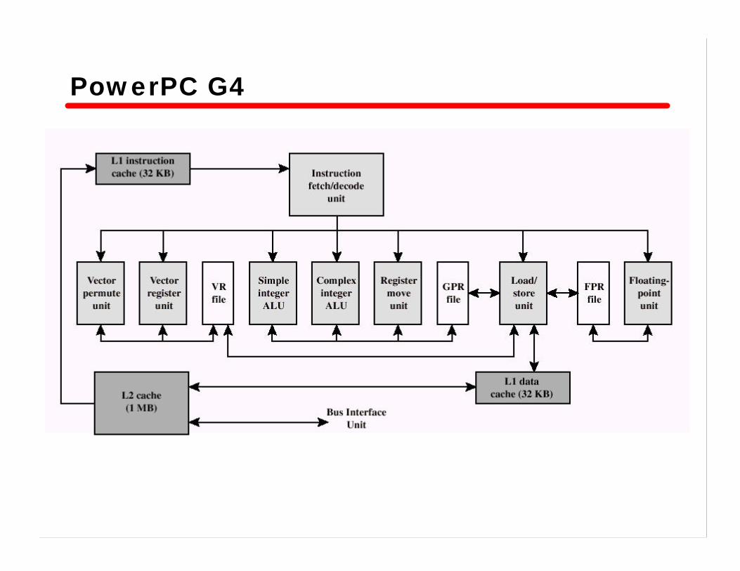
PowerPC G4

Comparison of Cache Sizes