chapter 4: dc generators - oakland universityfrick/ee4220-em_dynamics/lecture5.pdf · chapter 4: dc...
TRANSCRIPT
9/8/2003 Electromechanical Dynamics 1
Chapter 4: DC Generators
9/8/2003 Electromechanical Dynamics 2
Armature Reaction
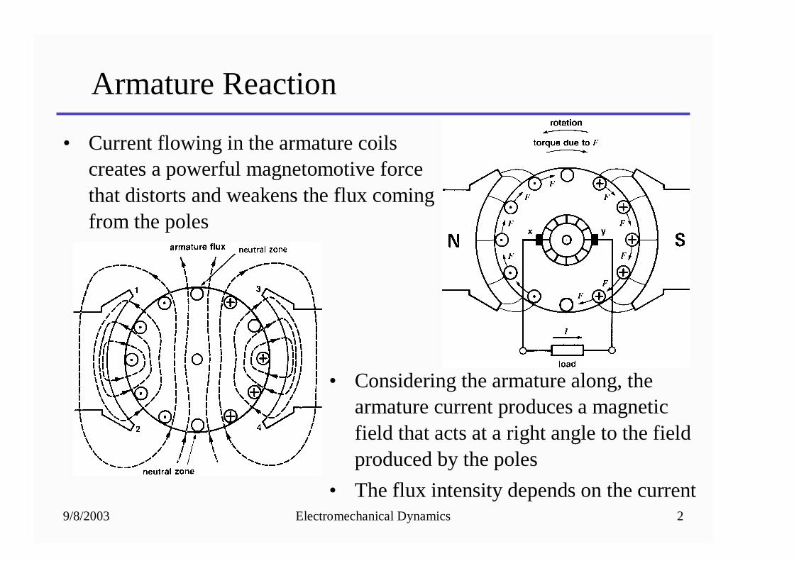
• Current flowing in the armature coils creates a powerful magnetomotive force that distorts and weakens the flux coming from the poles
• Considering the armature along, the armature current produces a magnetic field that acts at a right angle to the field produced by the poles
• The flux intensity depends on the current
9/8/2003 Electromechanical Dynamics 3
Armature Reaction
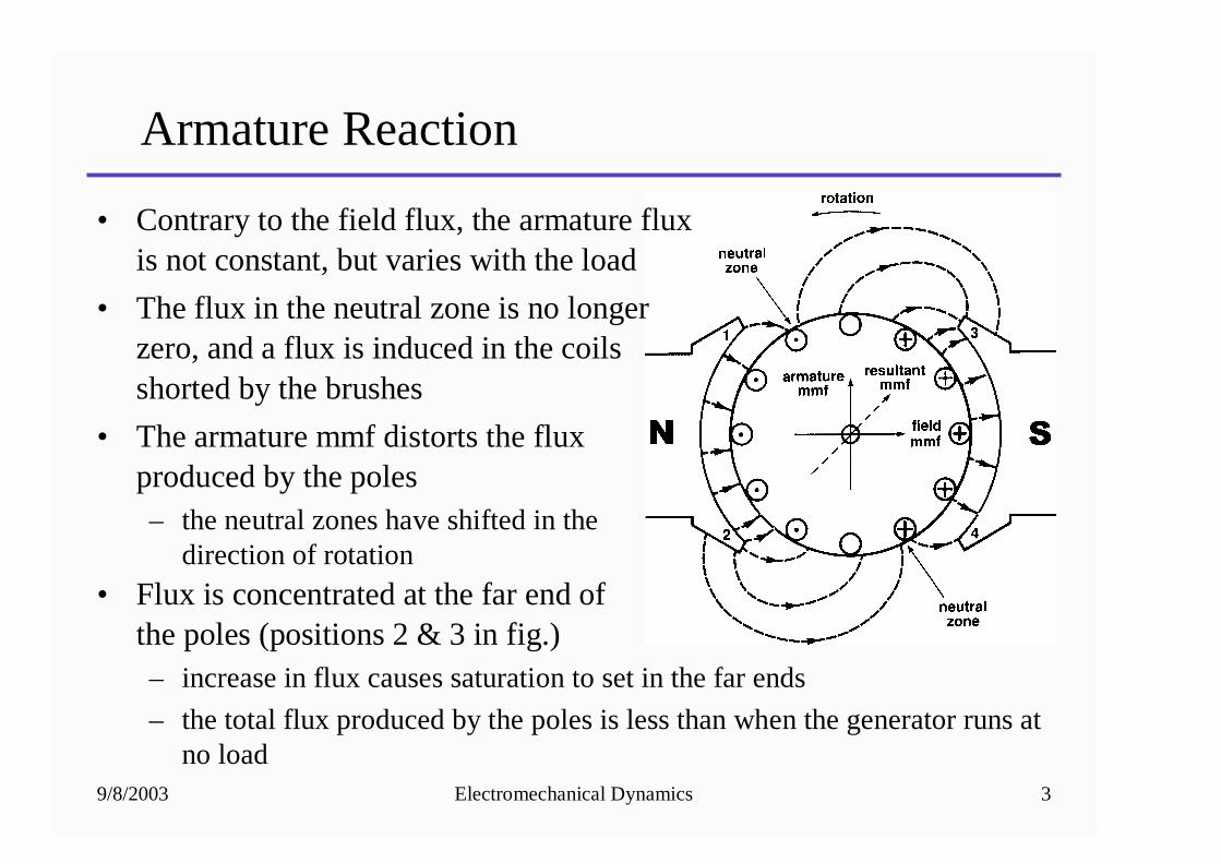
• Contrary to the field flux, the armature flux is not constant, but varies with the load
• The flux in the neutral zone is no longer zero, and a flux is induced in the coils shorted by the brushes
• The armature mmf distorts the flux produced by the poles– the neutral zones have shifted in the
direction of rotation
• Flux is concentrated at the far end of the poles (positions 2 & 3 in fig.)– increase in flux causes saturation to set in the far ends
– the total flux produced by the poles is less than when the generator runs at no load
9/8/2003 Electromechanical Dynamics 4
Improving Commutation
• The shift in the neutral zone causes an increase in arcing– we can move the brushes in the direction of rotation to reduce
the arcing
• For time varying loads, the fluctuating current raises and lowers the armature magnetic-motive force and the neutral zone shifts back and forth– it is not practical to continuously move the brushes to
minimize the arcing
– for small machines the brushes are set in an intermediate position to ensure reasonably good commutation at all loads
9/8/2003 Electromechanical Dynamics 5
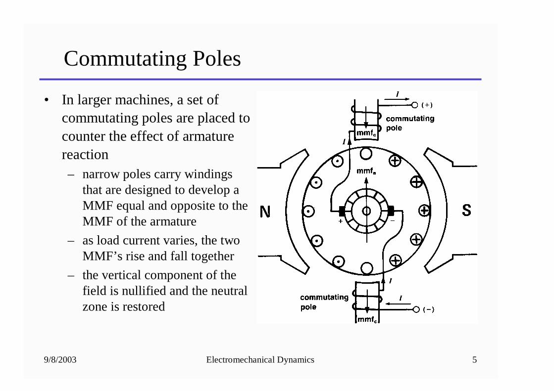
Commutating Poles
• In larger machines, a set of commutating poles are placed to counter the effect of armature reaction– narrow poles carry windings
that are designed to develop a MMF equal and opposite to the MMF of the armature
– as load current varies, the two MMF’s rise and fall together
– the vertical component of the field is nullified and the neutral zone is restored
9/8/2003 Electromechanical Dynamics 6
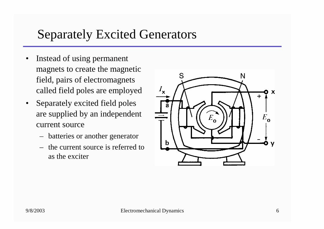
Separately Excited Generators
• Instead of using permanent magnets to create the magnetic field, pairs of electromagnets called field poles are employed
• Separately excited field poles are supplied by an independent current source– batteries or another generator
– the current source is referred to as the exciter
9/8/2003 Electromechanical Dynamics 7
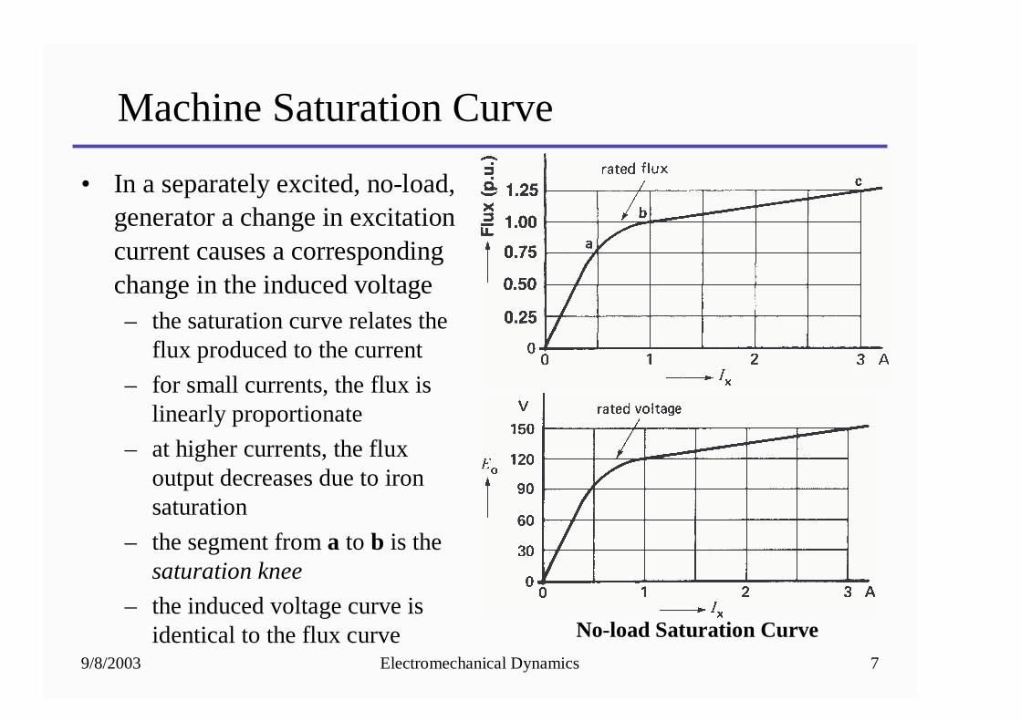
Machine Saturation Curve
• In a separately excited, no-load, generator a change in excitation current causes a corresponding change in the induced voltage– the saturation curve relates the
flux produced to the current
– for small currents, the flux is linearly proportionate
– at higher currents, the flux output decreases due to iron saturation
– the segment from a to b is the saturation knee
– the induced voltage curve is identical to the flux curve No-load Saturation Curve
9/8/2003 Electromechanical Dynamics 8
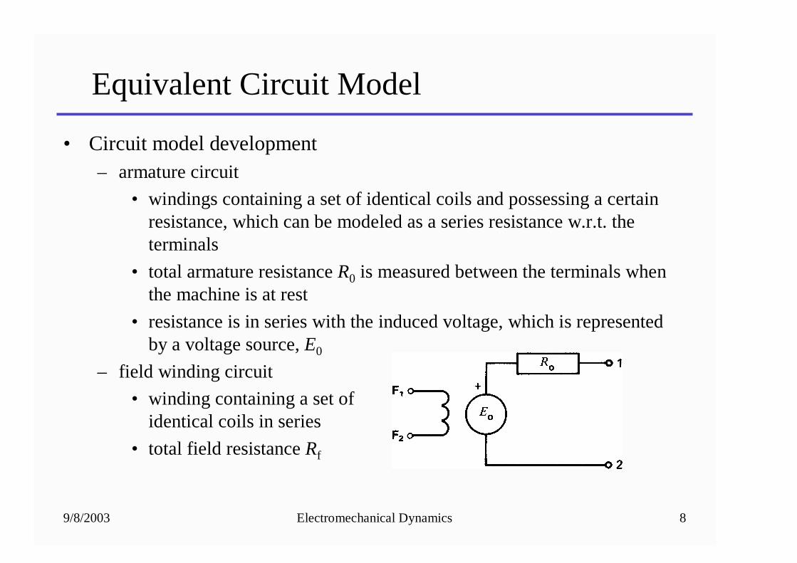
Equivalent Circuit Model
• Circuit model development– armature circuit
• windings containing a set of identical coils and possessing a certain resistance, which can be modeled as a series resistance w.r.t. the terminals
• total armature resistance R0 is measured between the terminals when the machine is at rest
• resistance is in series with the induced voltage, which is represented by a voltage source, E0
– field winding circuit
• winding containing a set of identical coils in series
• total field resistance Rf
9/8/2003 Electromechanical Dynamics 9
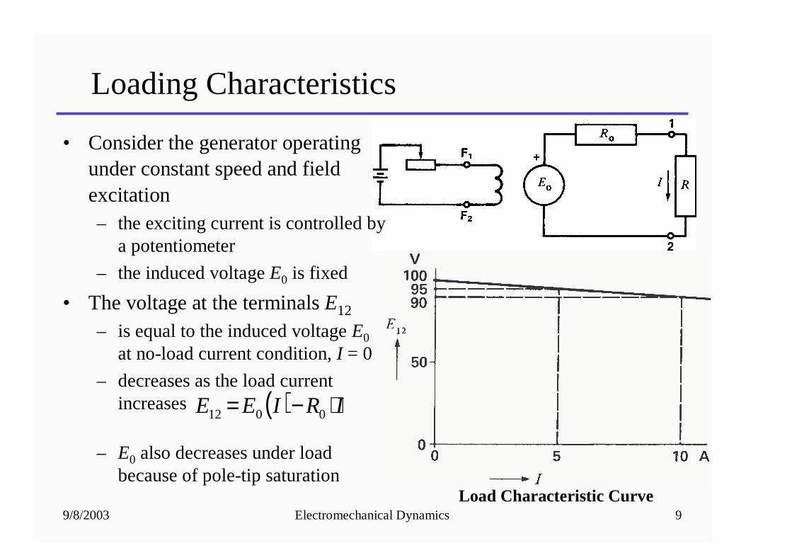
Loading Characteristics
• Consider the generator operating under constant speed and field excitation– the exciting current is controlled by
a potentiometer
– the induced voltage E0 is fixed
• The voltage at the terminals E12
– is equal to the induced voltage E0
at no-load current condition, I = 0
– decreases as the load current increases
– E0 also decreases under load because of pole-tip saturation
Load Characteristic Curve
( ) IRIEE ⋅−= 0012
9/8/2003 Electromechanical Dynamics 10
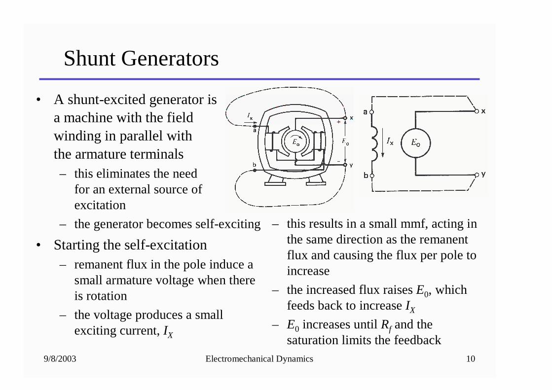
Shunt Generators
• A shunt-excited generator is a machine with the field winding in parallel with the armature terminals– this eliminates the need
for an external source of excitation
– the generator becomes self-exciting
• Starting the self-excitation– remanent flux in the pole induce a
small armature voltage when there is rotation
– the voltage produces a small exciting current, IX
– this results in a small mmf, acting in the same direction as the remanent flux and causing the flux per pole to increase
– the increased flux raises E0, which feeds back to increase IX
– E0 increases until Rf and the saturation limits the feedback
9/8/2003 Electromechanical Dynamics 11
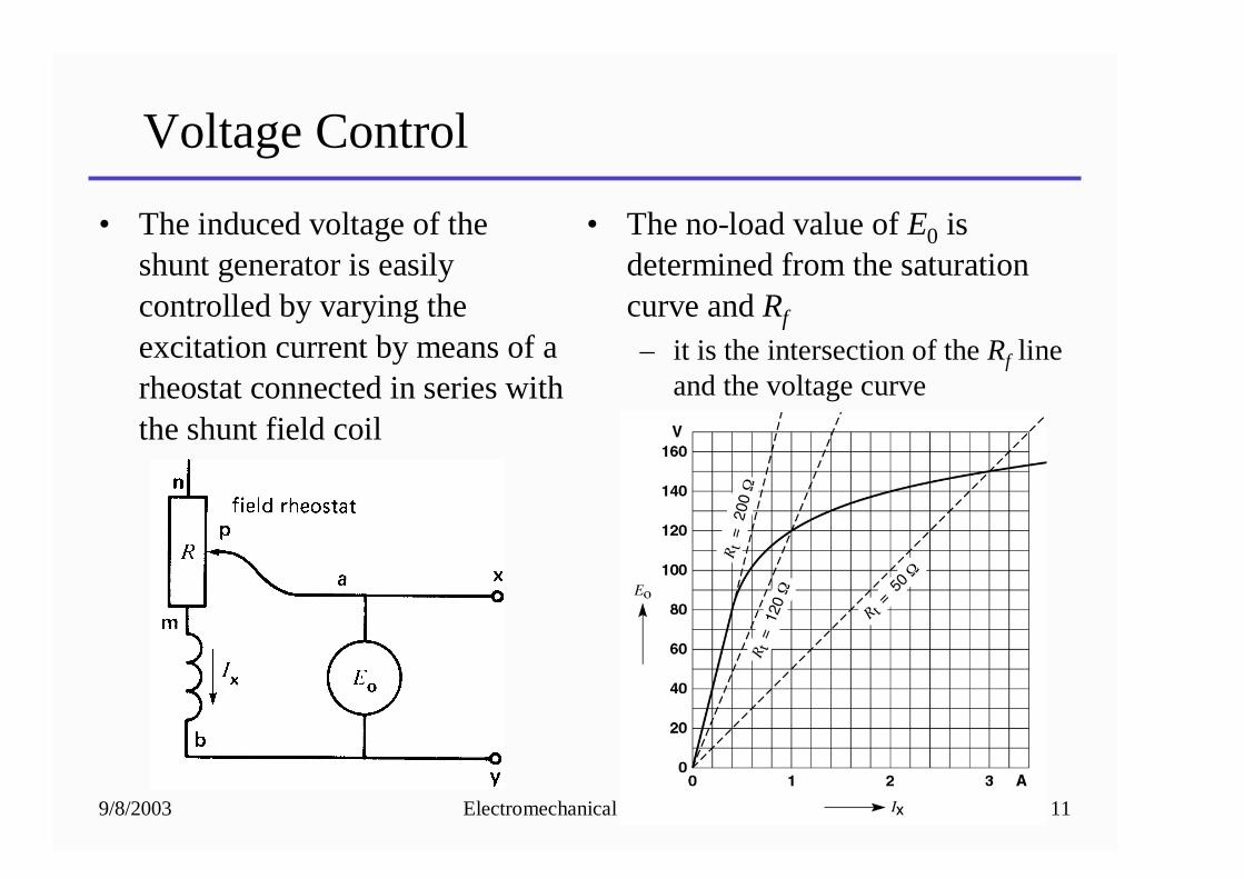
Voltage Control
• The induced voltage of the shunt generator is easily controlled by varying the excitation current by means of a rheostat connected in series with the shunt field coil
• The no-load value of E0 is determined from the saturation curve and Rf
– it is the intersection of the Rf line and the voltage curve
9/8/2003 Electromechanical Dynamics 12
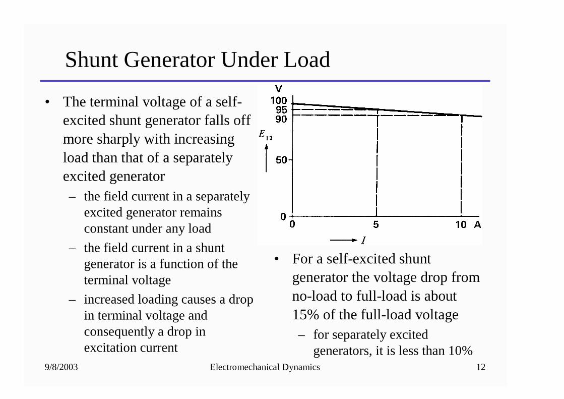
Shunt Generator Under Load
• The terminal voltage of a self-excited shunt generator falls off more sharply with increasing load than that of a separately excited generator– the field current in a separately
excited generator remains constant under any load
– the field current in a shunt generator is a function of the terminal voltage
– increased loading causes a drop in terminal voltage and consequently a drop in excitation current
• For a self-excited shunt generator the voltage drop from no-load to full-load is about 15% of the full-load voltage– for separately excited
generators, it is less than 10%
9/8/2003 Electromechanical Dynamics 13
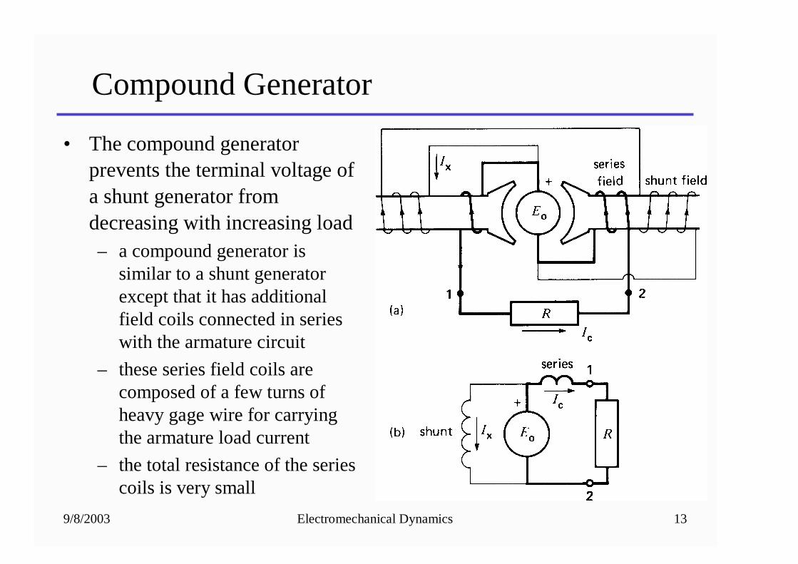
Compound Generator
• The compound generator prevents the terminal voltage of a shunt generator from decreasing with increasing load– a compound generator is
similar to a shunt generator except that it has additional field coils connected in series with the armature circuit
– these series field coils are composed of a few turns of heavy gage wire for carrying the armature load current
– the total resistance of the series coils is very small
9/8/2003 Electromechanical Dynamics 14
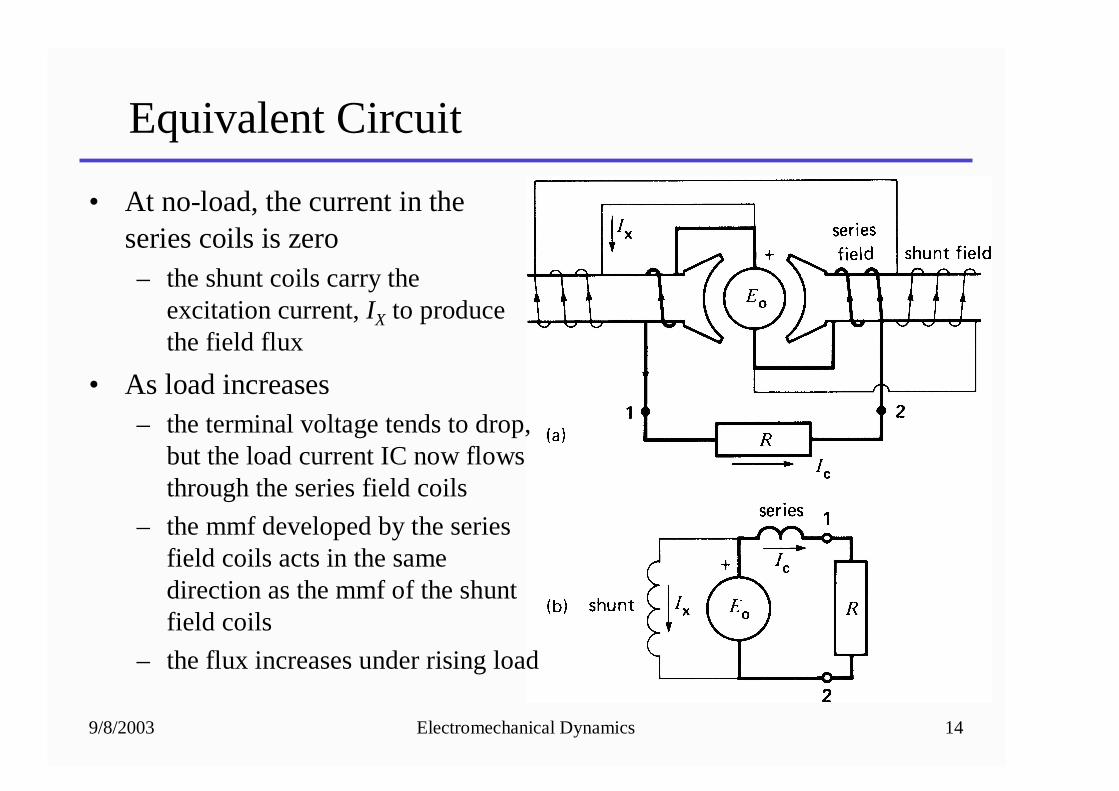
Equivalent Circuit
• At no-load, the current in the series coils is zero– the shunt coils carry the
excitation current, IX to produce the field flux
• As load increases– the terminal voltage tends to drop,
but the load current IC now flows through the series field coils
– the mmf developed by the series field coils acts in the same direction as the mmf of the shunt field coils
– the flux increases under rising load
9/8/2003 Electromechanical Dynamics 15
Differential Compound Generator
• In a differential compound generator, the mmf of the series field acts opposite to the shunt field– under load, the terminal voltage falls drastically with
increasing load
– the series field circuit is reversed in polarity to make a compound generator into a differential compound generator
– useful in welding applications
– limits short-circuit currents
9/8/2003 Electromechanical Dynamics 16
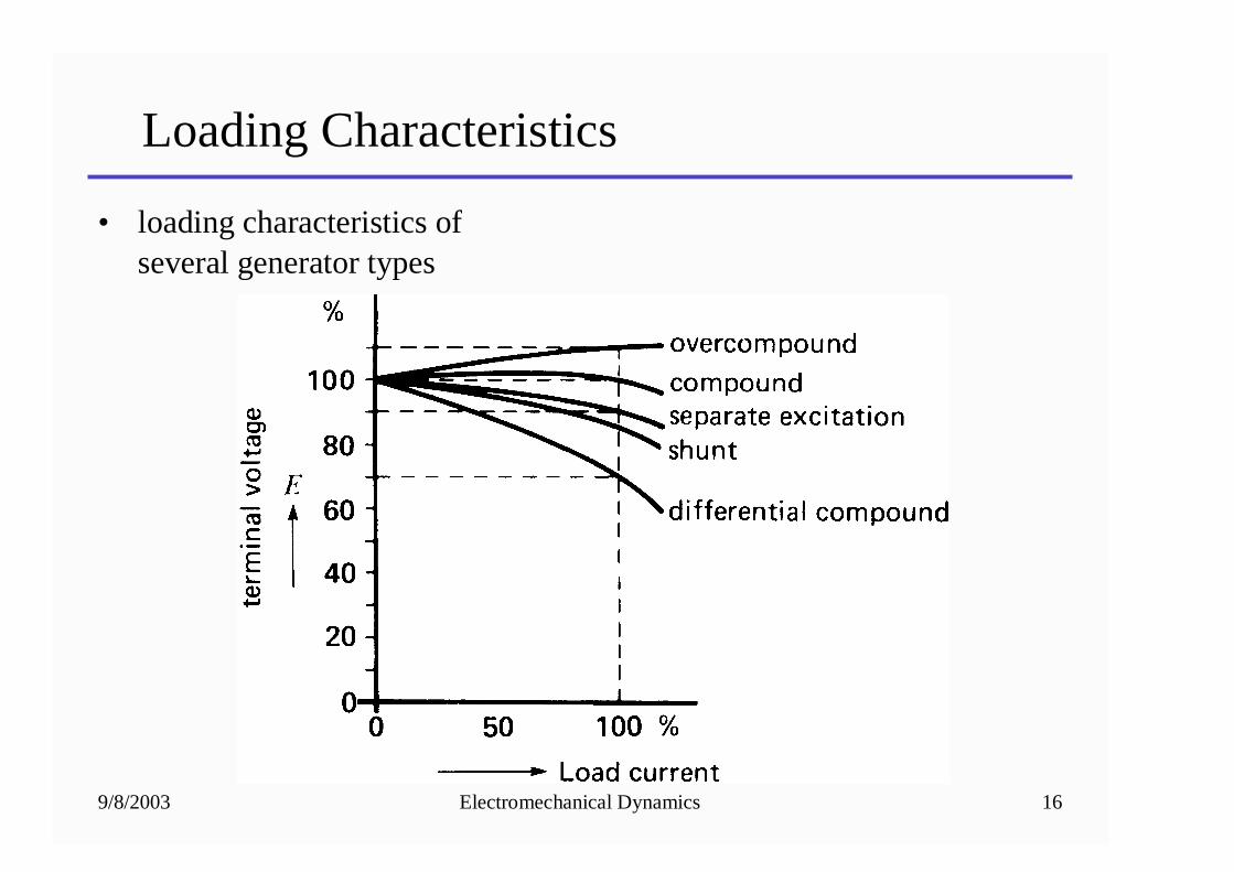
Loading Characteristics
• loading characteristics of several generator types