chapter 4: digital transmission - new mexico institute of mining …cs353/lectures/lecture_04... ·...
TRANSCRIPT

(Line coding, Block coding, Scrambling) Chapter 4: Digital Transmission
Converting a sequence of data bits (text, numeric, audio, or video) into a digital signal, at the sender, then recovering the original bit sequence from the signal, at the destination
Digital to digital conversion (Line Coding)
data rate ≡ bit rate(N) b/s, signal rate(S) ≡ baud ratechange/s (Hz) Let r bit/change, Nmax = S * r * 1/c where c is and usually assumed ½ For the average calculations of S&N The goal is to increase the data rate (information flow) while decreasing band rate (better utilization of channel BW, cheaper links)
Long strings of 0’s or 1’s causes a drift of the obtained baseline, hence “baseline wandering” that leads to incorrect bit decoding.
Factors to consider in digital signaling:
1) Baseline wandering: The receiver averages the signal power (Baseline
), and uses it to decode the received signal bit value.
2) DC components: Constant level for long period of time creates very low frequency components in the frequency spectrum, that might not pass through some medium (e.g., TP of 200Hz 3000Hz). Hence, we need to remove the DC from the Digital Signal .
3) Self-Synchronization: To match the sender and receiver clocks, hence match the bit intervals at both ends for correct decoding.
Transitions in the digital signal act as self-synch altering the receiver to the start, mid, or end of the bit, resetting its clock in case it is out of synch.
4) Built in error detection: It is good to add extra bits to the Tx data for error detection (and possibly correct). 5) Noise and interference immunity:
Encoding/ Decoding complexity: complex - high cost

Line Coding Schemes
4.10
Figure 4.4 Line coding schemes
("HARD"coding of voltage over the channel)
1) Unipolar: NRZ (non return to zero) No signal return to zero level at the mid of bit.
Problem: Large DC component many low frequency
components. Hence needs based BW. Difficult src. to dest. synchronization.
4.11
Figure 4.5 Unipolar NRZ scheme

2) Polar: To alleviate the DC and synchronization problems, 2
voltage levels are used for digits encoding –ve and +ve.
A) NRZ:i) NRZ_level: +ve volt encodes 0,
None Return to Zero
–ve volt encodes 1 Very sensitive to polarity change, if happened, all 0’s become 1’s and vice versa. ii) NRZ_ Invert: instead of using voltage level for
encoding the notion of transition At the bit start: transition exists encodes 1
is used.
No transition encodes 0 Has lesser DC wandering than NRZ-I and better src/dest synchronization.
4.12
Figure 4.6 Polar NRZ-L and NRZ-I schemes

B) RZ: It is the solution of NRZ synchronization problem (i.e., deciding when a bit starts and ends)
Return to Zero:
Uses 3 levels of voltage to encode a digit: -ve, 0 , +ve. There is a mid bit transition to return to 0, from whichever level it was before.
Much better baseline solution; but complex with 3 voltage levels.
4.17
Figure 4.7 Polar RZ scheme

C) Biphase:Still there is a mid bit transition where the duration of the bit is divided into two levels one in the 1st half of the bit and a different one in the 2nd:
Combines RZ and NRZ_L.
Two encodings: i. Manchester Encoding (ME):
At mid bit: high to low encodes 0 Low to high encodes 1
ii. Differential ME: At start of the bit: transition encodes 0 No transition encodes 1
4.18
Figure 4.8 Polar biphase: Manchester and differential Manchester schemes
Good noise immunity (why?!).
Best synchronization, yet worst BW utilization (lose of half of
the channel baud rate [r=1/2]!).
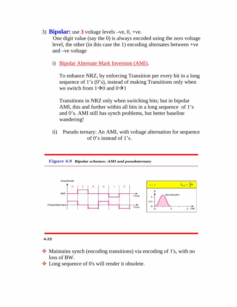
3) Bipolar: use 3 voltage levels –ve, 0, +ve. One digit value (say the 0) is always encoded using the zero voltage
level, the other (in this case the 1) encoding alternates between +ve and –ve voltage
i) Bipolar Alternate Mark Inversion (AMI)
.
To enhance NRZ, by enforcing Transition per every bit in a long sequence of 1’s (0’s), instead of making Transitions only when we switch from 10 and 01
Transitions in NRZ only when switching bits; but in bipolar
AMI, this and further within all bits in a long sequence of 1’s and 0’s. AMI still has synch problems, but better baseline wandering!
ii) Pseudo ternary: An AMI, with voltage alternation for sequence
of 0’s instead of 1’s.
4.22
Figure 4.9 Bipolar schemes: AMI and pseudoternary
Maintains synch (encoding transitions) via encoding of 1's, with no loss of BW.
Long sequence of 0's will render it obsolete.

4) The “tradeoff” between synch and baseline wandering, and DC components has resulted in many digital encoding that achieves some and leave some!
Multilevel Schemes:
There is a tradeoff between synch&DC versus
BW; example ME, DME.
To balance BW and synch-DC components, we will have to devise an encoding technique that encodes m_bit blocks of digits “mB”, instead of 1 bit (1B), into blocks of L multilevel voltages (L > 2) of n digits “nL” : mBnL .
mB nL i.e. 2m is <= Ln
Then we can “smartly” select 2m codes out of the resulting Ln larger codes to map our original data blocks; the remaining (Ln – 2m) is to be used for control. i) 2B1Q: Two binary, one quaternary (used in DSL lines) Four levels of voltage signal, each encodes 2 bits. No self-synch for
long same double bits. Required bandwidth = Bave = N / 4 Pros.: simple, typical codes balance voltage and lesser baseline
wandering. Cons.: long sequences of zeros, or "01" will have constant DC output.
4.24
Figure 4.10 Multilevel: 2B1Q scheme
(
There is a typo error in your textbook, Fig.4.10 above r =2 not 1/2)
r =2

ii) 8B6T: Eight binary, six ternary (used in 100 Base- 4T) Encodes a pattern of 8 bit 6 signal elements, each is one of 3 levels (+ve, 0, -ve) Hence, mapping 256 2 7293 combinations, with 473 redundant
patterns to leave out due to poor encoding (bad synch, DC balance), also aiding in code distance (separation) for easy error detection.
Hence, we can easily pick patterns of weight 0 or +1 DC values, if two consecutive patterns are of weights +1 DC, we send the 1st one as is, the 2nd is invented to be of weight – 1, hence canceling the 1st + 1, for a DC balance.
Bavg (change/sec) = ½ * N bit/sec * (6 / 8) change/bit where: B is the average signal baud and N is the bit rate r = (8/6)= 1.3333 bit/change > 1, good! Since we make 6 changes (6 symbols of 3-levels voltages) for every 8 bits.
4.25
Figure 4.11 Multilevel: 8B6T scheme
At the receiver, the shaded yellow code in Fig. 4.11 above is to be re-inverted (as is it reads "− + + − 0 −" ) to yield "+ − − + 0 +", then remapped into 01010000 .

iii) 4D- PAM5 : Four-dimensional Five level Pulse Amplitude Modulations. To further enhance the BW signal utilization, we use Five
Hence
voltage levels ((+2, +1, 0, -1, -2), but the 0volt is used for error detection
Four voltages are used only (i.e., 8B4Q) moreover we use four Tx wires to transmit 4Q signals, simultaneously i.e., one signal change only per wire. Hence it looks as if we had 8B1Q
Signal_baud (change/sec) = bit_rate (bit/sec)* (1/ 8) (change/bit)
(from the prospective of each 125 MBd lines)
Each wire is 125MbBd that carry 250Mb/s (i.e., (8/4)=2 bits per change).
4.26
Figure 4.12 Multilevel: 4D-PAM5 scheme
The complexity of the system (4 levels of voltages, each encoding 2 bits) and use of four 125 M baud Tx wires paid off in the gain of BW utilization (up to 1Gb/s) and reasonable synchronization!

3 voltage levels, -ve, 0, +ve works on “ inversion” not “level” Multiline Tx: MLT-3
Encoding based on transition: (rules) 1 – next bit is 0 then2 – next bit is 1 and current voltage <> 0
no transition then
3 –next bit is 1 and current voltage = 0 next level is 0
then last nonzero level
next level is the opposite of the
4.27
Figure 4.13 Multitransition: MLT-3 scheme
MLT- 3 is a complex system and its signal rate is the same as NRZ – I, then why use it?? (page 114 for answer) In the case of long sequence of 1's:
= 1/2 its bit rate
both encodings have periodic signal of frequency (i.e., signal rate) = in case of NRZ-I --> 1/(2bits durations)
=
and
in case of MLT-3 --> 1/(4 bits durations as shown above Fig 4.13-b)
= 1/4 its bit rate
Hence, MLT-3 has lower signal rate, requiring lesser cable BW.
Problems? Long sequence of 0’s, No synch

Block Coding Used to overcome the synch problems of long zeros in NRZ-I.
: ("SOFT" coding, NO complex multilevel voltage)
Still we need to use NRZ-I (actual line signaling) as second stage. Synch vs. BW complexity mB/ nB where n > m lose of BW, but less complexity and better handling of
long sequence of similar bits (0's in case of NRZ-I).
4.30
Figure 4.14 Block coding concept
EVERY BLOCK CODING MUST BE FOLLOWED BY A LINE CODING (WHY?)
i) 4B/5B
• In our selection we pick up combinations of 5B as follows:
: Every 4 bits are encoded using 5 bits mapping 24 into 25 combination. The difference is used for control.
a) No more than one leading (most sig. bit) zero. b) No more than two trailing (least sig. bit) zeros. a)&b) no more than 3 consecutive zeros in any coding. Hence we can use it before the NRZ- I (has good signal band rate better than ME/DME biphase) and reduce its input zeros reduce synch problem! In Summary: It balances between BW utilization and synchronization, instead of losing BW and gaining full synch as the biphase
4.31
Figure 4.15 Using block coding 4B/5B with NRZ-I line coding scheme
.

- The disparity controller takes care of long 0’s and 1’s, if detected then the appropriate complementation is applied.
ii) 8B/10B:
- There are 768 = 210 – 28 of redundant combinations used for disparity (see below) and error (large distances between codes) control.
- Baud rate = bit rate * (10/8) (i.e., drawback of Baud > Bit-rate) - Much better error control and synchronous than 4B/5B, but it
has two units (more cost and design complexity). - Splits into 5B/6B and 3B/4B for simpler mapping tables
(allowing for H/W implementation!?),
- The Disparity unit is to alleviate the problem of too many zeros/ones in our combined codes (6+4) due to the separate mapping choices, hence it complements the 10 bit if it help to control unwanted long sequence of bits (0's in case of NRZ-I).
nothing about better utilization of BW, the Baud rate = bit-rate * (10/8), as above !
4.35
Figure 4.17 8B/10B block encoding
Scrambling Biphase and block/NRZ encoding are not good for long distance networks, Bipolar AMI encoding has no DC and still with narrow BW! (good!). Yet, it suffers from long sequences of zeros problem. The following
(AMI with Scrambling)
scrambling
encodings are to alleviate such problem.
1) B8ZS Where V: Violation of AMI encoding,
: Any sequence of 8 zeros = 000VB0VB
B: bipolar AMI encoding

4.37
Figure 4.19 Two cases of B8ZS scrambling technique
2) HDB3: High-density bipolar 3- zeros. Any 4 consecutive zeros =
i) 000V if # of nonzero pulses after last substitution is odd making total non zero pulses even
ii) B00V of # of nonzero pulses after last substitution is even making total nonzero pulses even. (ii is assumed initially)
4.39
Figure 4.20 Different situations in HDB3 scrambling technique

Analog to Digital Conversion
• For the digital Tx of analog data (e.g. audio) for high quality Tx, we use "A– to – D" (remember not all data in/out of computers are digital; we also have analog input/output data
that need to be communicated too)
1- Pulse Code Modulation (PCM):
Encoding1) the analog signal is sampled,
: 3 stages process:
2) The sampled signal is quantized, 3) The quantized values are encoded in bits.
4.42
Figure 4.21 Components of PCM encoder
According to “ Nyquist theorem”, in order to successfully reconstruct the input signal at the receiver, we must sample it at the sender at least twice of its highest frequency. Assuming low-pass filter where BW = fmax then Nyquest: Nmax (b/s) = 2 * B log2 L = 2 * fmax (L = 2 for binary) Decoding process: 1) Make and connect samples 2) Low- pass filter

2-Delta Modulation (DM):
4.60
Figure 4.28 The process of delta modulation
Because of the PCM complexity, and the required number of bits per sample (high), DM is developed where instead of sending the absolute value of the sample, DM sends only the change 0 (-ve change), 1 (+ve change), based on a threshold “d “ of signal amplitude. Encoding 2) for the remaining samples, detect if the next sample value is:
: 1) send the first sample voltage level of the signal,
i) lower than the last one: send 0. ii) higher than the last one: send 1. Decoding 2) for every 0, go down δ volt, and for 1 go up δ volt.
: 1) plot the first sample value,

1) Parallel: The Tx of n bits at a time, using n wires as a block. Explusive (n wires), but fast, hence limited to short distances.
Transmission Modes:
2) Serial: The Tx of one bit at a time, in sequence over one wire. Low
cost, but requires “ parallel_to_serial” device at the sender, and “ serial_to_parallel” at the receiver.
Serial Tx has 3 modes:
-
1) Asynchronous: No timing to synch the sender and receiver; they both agree in certain pattern (bytes) to exchange with the aid of an extra bit(s) to decide the “start” and “end” of each pattern in addition to inter bytes “gaps”. Typically, for delimiting a byte, there will be start bit (0) and end bit(s) of 1(‘s). Then, after each byte there will be a gap (idle channel, or extra 1’s). Eventhough there is no sender/receiver synch at the “ byte” level; there is sender/receiver synch at the bit-duration level, within each byte. Adv: Simplicity—lesser clocking.,
Problem: Slow, wasting BW (delimiting bits, inter-byte gapes)
2) Synchronous: The Tx of a sequence of bits grouped as multiple bytes frames, each is a stream of bits with no extra synch bits to delimit its bytes; only inter frame gaps for frames separation. The sender and receiver have to synch their clocks
Adv: Speed, very amenable for multimedia traffic.
for the process of frame interpretation and byte extraction.
Problem: Synch complexity, Clock Jettering, varying interframe delays
a) Plesynchronous: Almost Synchronous, but it allows for some delay
variation within some tolerance +/- 50 ppm (parts per million)
b) Isochronous: For real time audio and video conferencing, we need no variation in the interframe delays, i.e. fixed arrival rate.

Chapter 5:
Analog Transmission Digital_To_Analog• Encoding digital data into analog signals carriers of different amplitude,
frequency, and phase shifts, moving them over analog networks, e.g., Public telephone network with limited BW 300- 3400 Hz only.
:
• WHEN?
5.3
Figure 5.1 Digital-to-analog conversion
Wireless medium (forcing broadband Tx).
5.4
Figure 5.2 Types of digital-to-analog conversion

How?
A) Amplitude shift keying (ASK): Varying the carrier amplitude for encoding: Since fc (carrier freq.) is at
the center of the BW of the channel BW. We can select our carrier frequency fc to fit our existing channel in hand (flexibility advantage).
Bit rate = Signal Baud (one bit per change)
5.8
Figure 5.3 Binary amplitude shift keying
5.9
Figure 5.4 Implementation of binary ASK

5.12
Figure 5.5 Bandwidth of full-duplex ASK used in Example 5.4
B) Frequency Shift Keying: Varying the carrier frequencies use of diff
carrier frequencies. Inefficient BW utilization (why?) Signal Baud = Bit rate (one bit per change)
5.13
Figure 5.6 Binary frequency shift keying

C) Phase shift Keying (PSK): Varying the phase shift of the carrier to
encode digits. Bit rate = Signal Baud (one bit per change)
5.18
Figure 5.9 Binary phase shift keying
D) Quadrative PSK (QPSK): Instead of encoding 1 bit per each of the 2
phases, we use 4 different phases to encode 2 bits = log2 (4 phases). Bit rate = Signal Baud * 2 (2 bits per change) E) Quadrative Amplitude Modulation (QAM): It varies both the amplitude and the phase of the carrier analog sinusoidal
wave in order to encode digits in a much higher rate than the above techniques.
In X-QAM (where X is the number of encoding point in the 4-quadrant): Bit rate = Signal Baud * log2 X
5.26
Figure 5.14 Constellation diagrams for some QAMs
Example: with 100 MHz 4096-QAM channel the data rate is 100 M * log2 4096 = 1,200 M b/s (huge)