chapter 4 in waveguides · figure 1. (a) coupled iris filter, (b) corrugated waveguide filter, (c)...
TRANSCRIPT
Chapter 4
Mathematical Analysis of Electrical Breakdown Effectsin Waveguides
Isaac Medina and Primo-Alberto Calva
Additional information is available at the end of the chapter
http://dx.doi.org/10.5772/intechopen.76973
Provisional chapter
Mathematical Analysis of Electrical Breakdown Effectsin Waveguides
Isaac Medina and Primo-Alberto Calva
Additional information is available at the end of the chapter
Abstract
The designers of microwave devices in the industry use the analytical solutions of thecorona discharge equation to determine the minimum power breakdown threshold, in aparticular device, such as waveguides and filters, and know whether it is in theestablished margins. There are two main ways to determine the breakdown threshold ofa waveguide analytically; the most commonly used describes the plasma density genera-tion completely as a function of the geometry by using the characteristic diffusion length,while the second is a more thorough method that involves the use of the effective diffu-sion length which considers collision frequency and electric field into the equations. Hencethe aim of the designers is to obtain the closest results to experimental results, bothmethods must be considered in addition to the environmental changes so that they knowthe operational limits. This chapter describes the different methods to obtain analyticalresults for the breakdown threshold in any rectangular waveguide device, the influence ofenvironmental conditions in the analysis and the inhomogeneous electric field effectinside the devices.
Keywords: electrical breakdown threshold, corona, characteristic diffusion length,waveguide filters, effective diffusion length
1. Introduction
Traffic capacity in a high-frequency scenario where waveguides are involved is generallylimited by two main factors: bandwidth and input power [1]. In cases where the atmosphericpressure is a factor, such as satellite communications, the maximum input power of the signalis determined by several factors, among which are the geometry of the device, the collision
© 2016 The Author(s). Licensee InTech. This chapter is distributed under the terms of the Creative Commons
Attribution License (http://creativecommons.org/licenses/by/3.0), which permits unrestricted use,
distribution, and eproduction in any medium, provided the original work is properly cited.
DOI: 10.5772/intechopen.76973
© 2018 The Author(s). Licensee IntechOpen. This chapter is distributed under the terms of the CreativeCommons Attribution License (http://creativecommons.org/licenses/by/3.0), which permits unrestricted use,distribution, and reproduction in any medium, provided the original work is properly cited.
frequency of the molecules and free electrons and the intrinsic characteristics of the propagat-ing medium itself, that is, air or nitrogen [2].
Waveguides are conductor hollow tubes, generally consisting of a circular, elliptical, or rectan-gular cross-section. The cross-section dimensions are chosen by designers in such a way thatelectromagnetic waves propagate inside the guide. A waveguide can have several shapes andsizes, and frequently its performance is a function of the radiofrequency (RF) routing signals;this means that the way the wave is propagating inside the guide. Rectangular waveguides arethe most commonly used; this is because they are easily fabricated, they have a very broadbandwidth and they present low losses within their operating frequencies [3].
Rectangular waveguides operate only in certain frequency bands, depending on the cross-section dimensions. Waveguide geometry determines the highest operating wavelength, thismeans, higher waveguide sizes operate at lower frequencies.
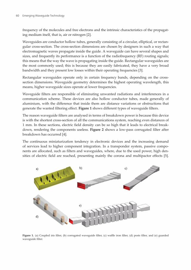
Waveguide filters are responsible of eliminating unwanted radiations and interferences in acommunication scheme. These devices are also hollow conductor tubes, made generally ofaluminium, with the difference that inside them are distance variations or obstructions thatgenerate the wanted filtering effect. Figure 1 shows different types of waveguide filters.
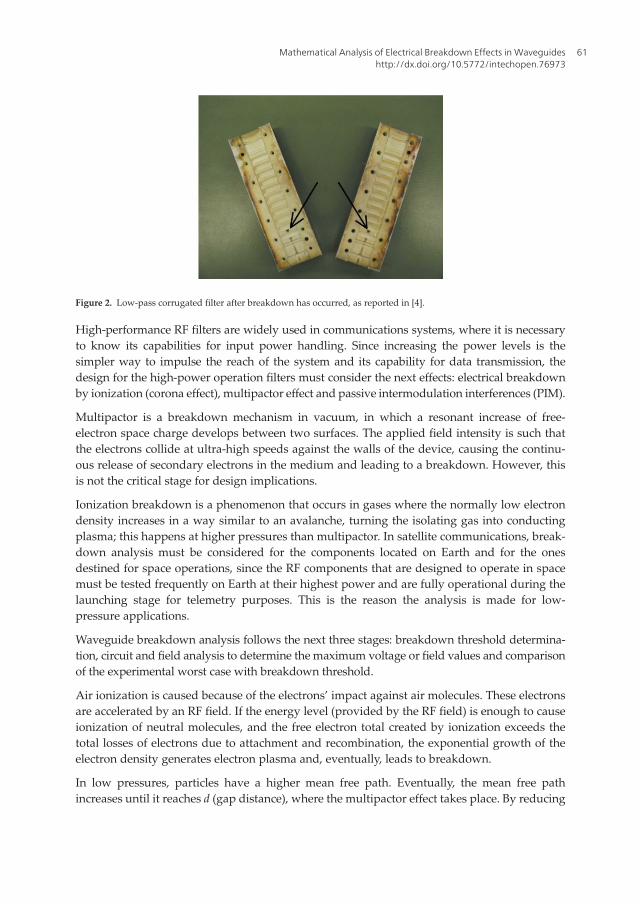
The reason waveguide filters are analysed in terms of breakdown power is because this deviceis with the shortest cross-section of all the communications system, reaching even distances of1 mm. In these sections, electric field density can be so high that it leads to electrical break-down, rendering the components useless. Figure 2 shows a low-pass corrugated filter afterbreakdown has occurred [4].
The continuous miniaturization tendency in electronic devices and the increasing demandof services lead to higher component integration. In a transponder system, passive compo-nents are allocated, such as filters and waveguides, where, due to the used power, high den-sities of electric field are reached, presenting mainly the corona and multipactor effects [5].
Figure 1. (a) Coupled iris filter, (b) corrugated waveguide filter, (c) waffle iron filter, (d) posts filter, and (e) guardedwaveguide filter.
Emerging Waveguide Technology60
High-performance RF filters are widely used in communications systems, where it is necessaryto know its capabilities for input power handling. Since increasing the power levels is thesimpler way to impulse the reach of the system and its capability for data transmission, thedesign for the high-power operation filters must consider the next effects: electrical breakdownby ionization (corona effect), multipactor effect and passive intermodulation interferences (PIM).
Multipactor is a breakdown mechanism in vacuum, in which a resonant increase of free-electron space charge develops between two surfaces. The applied field intensity is such thatthe electrons collide at ultra-high speeds against the walls of the device, causing the continu-ous release of secondary electrons in the medium and leading to a breakdown. However, thisis not the critical stage for design implications.
Ionization breakdown is a phenomenon that occurs in gases where the normally low electrondensity increases in a way similar to an avalanche, turning the isolating gas into conductingplasma; this happens at higher pressures than multipactor. In satellite communications, break-down analysis must be considered for the components located on Earth and for the onesdestined for space operations, since the RF components that are designed to operate in spacemust be tested frequently on Earth at their highest power and are fully operational during thelaunching stage for telemetry purposes. This is the reason the analysis is made for low-pressure applications.
Waveguide breakdown analysis follows the next three stages: breakdown threshold determina-tion, circuit and field analysis to determine the maximum voltage or field values and comparisonof the experimental worst case with breakdown threshold.
Air ionization is caused because of the electrons’ impact against air molecules. These electronsare accelerated by an RF field. If the energy level (provided by the RF field) is enough to causeionization of neutral molecules, and the free electron total created by ionization exceeds thetotal losses of electrons due to attachment and recombination, the exponential growth of theelectron density generates electron plasma and, eventually, leads to breakdown.
In low pressures, particles have a higher mean free path. Eventually, the mean free pathincreases until it reaches d (gap distance), where the multipactor effect takes place. By reducing
Figure 2. Low-pass corrugated filter after breakdown has occurred, as reported in [4].
Mathematical Analysis of Electrical Breakdown Effects in Waveguideshttp://dx.doi.org/10.5772/intechopen.76973
61

the atmospheric pressure, there is a lower input power handling capacity until it reaches aminimum operation power; this is called critical pressure [4].
This chapter covers the ionization breakdown in atmospheric air analysis; the equations thatdescribe this consider different processes, such as the ionization, attachment and collisionfrequencies. Also, the analysis considers as variables the atmospheric pressure and electricfield intensity, considering contaminant-free dry air as the propagating medium. Nevertheless,due to the breakdown variability, the design of filters and waveguides is a controversial topicfor designers, who consider a wide tolerance range from 0 dB to 3 dB according to minimumbreakdown power [4, 5].
Corona breakdown is the process when electron plasma is created due to the ionization of thegas in areas where the electrical fields are high. Electrical fields in filters and waveguides canlead to corona effects at relatively low pressures (from 1 to 100 Torr), which, in atmosphericterms, are reached in the ionosphere (from 80 to 800 km). This phenomenon cannot occur invacuum conditions, since it is necessary for the presence of a gas to ionize [4].
2. Breakdown power threshold
There are different processes that can generate ions; these are by electronic impact, field effect,photo-ionization and thermos-ionization. For the analysis of filters and waveguides, the mostrelevant is by electronic impact, being directly proportional to the collision frequency betweenelectrons and molecules. The equation that describes the time evolution of free-electron gener-ation is [4, 6–8]:
∂n∂t
¼ ∇ D∇nð Þ� v! ∙∇nþ vi � vað Þn� βn2 þ P (1)
where νi and νa are the ionization and attachment frequencies, respectively, D is the diffusioncoefficient, β is the recombination coefficient and P is the electron production rate by externalsources; ∇ D∇nð Þ is the term that defines the diffusion of the electron cloud, from a high-
density area to a lower-density area, and is entirely space dependent; and v! ∙∇n is the convec-tive term that considers the possible movement of the gas.
For the corona effect analysis and from the pre-breakdown stage point of view, the recombina-tion term is discarded, since it is only relevant once the electron density is high enough, whichonly occurs when the electrical discharge has already begun. Also, the convective term has tobe discarded, since a stationary medium is assumed inside the waveguide devices, that is, thereis no relevant movement of the gas molecules. Additionally, the diffusion coefficient is consid-ered as space independent, since it is electric field independent [4]. The simplified equation is:
∂n∂t
¼ D∇2nþ vi � vað Þn (2)
Breakdown criteria are based on the fact that the electron density grows very fast once thereare more freed electrons than captured. Considering a scenario where there is no diffusion, and
Emerging Waveguide Technology62
a homogeneous field, due to the similar geometry among the parallel walls of the filter andwaveguides. Then, Eq. (2) results in:
∂n∂t
¼ vi � vað Þn (3)
and solving the derivative results in:
n tð Þ ¼ n0e vi�vað Þt: (4)
When νi > νa, there is an electron avalanche, and the breakdown condition for the continuouswaves can be simplified as:
dndt
¼ 0: (5)
As a consequence, the general equation to solve the breakdown threshold stage is:
D∇2nþ vi � vað Þn ¼ 0: (6)
Solving the Laplacian term from Eq. (6), and considering a Cartesian coordinate system, sincethe devices analysed are rectangular waveguides and filters, the equation leads to:
∂2n∂x2
þ ∂2n∂y2
þ ∂2n∂z2
þ νDn ¼ 0 (7)
where ν ¼ νi � νa is the effective ionization frequency. The rectangular waveguide device mustbe analysed from the cross-section, so the third term can be discarded, considering only thewidth and height of the guide.
∂2n∂x2
þ ∂2n∂y2
þ νDn ¼ 0 (8)
Establishing the solution as the product of two functions:
n x; yð Þ ¼ X xð ÞY yð Þ (9)
Substituting (9) in (8), knowing that the equation components are independent between them,it results in:
Yd2Xdx2
þ Xd2Ydy2
þ νDXY ¼ 0 (10)
and dividing by (9) we get:
1Xd2Xdx2
þ 1Yd2Ydy2
þ νD
¼ 0: (11)
This equation can be solved by proposing exponential solutions. Due to the independencyamong terms, the first term can be solved proposing a negative constant as a result:
Mathematical Analysis of Electrical Breakdown Effects in Waveguideshttp://dx.doi.org/10.5772/intechopen.76973
63
1Xd2Xdx2
¼ �σ
d2Xdx2
þ σX ¼ 0: (12)
An exponential solution for (12) is proposed and derived twice:
X xð Þ ¼ eγx (13)
X0 0xð Þ ¼ γ2eγx: (14)
Substituting (13) and (14) in (12), we get:
γ2eγx þ σeγx ¼ 0 (15)
It can be determined that:
γ2 þ σ ¼ 0γ ¼ � ffiffiffiffiffiffiffi�σ
p (16)
So, the general equation for X xð Þ is:
Aeiffiffiσ
px þ Be�i
ffiffiσ
px: (17)
By Euler, Eq. (17) can be rewritten as:
A cosffiffiffiσ
pxþ i sin
ffiffiffiσ
px½ � þ B cos
ffiffiffiσ
px� i sin
ffiffiffiσ
px½ �
Aþ Bð Þ cos ffiffiffiσ
pxþ A� Bð Þ sin ffiffiffi
σp
xk1 cos
ffiffiffiσ
pxþ k2 sin
ffiffiffiσ
px:
(18)
Considering the next border conditions, since there are no free electrons on the walls of thewaveguide:
X 0ð Þ ¼ 0, X að Þ ¼ 0 (19)
where a is the waveguide width distance. Then:
X 0ð Þ ¼ k1 ¼ 0X xð Þ ¼ k2 sin
ffiffiffiσ
px
X að Þ ¼ k2 sinffiffiffiσ
pb ¼ 0
(20)
The only possibility for a non-trivial solution is: sinffiffiffiσ
pb ¼ 0 ) ffiffiffi
σp
b ¼ mπ; resulting in
σ ¼ mπa
� �2 where m ¼ 1, 2, 3,…: By the same method, the second component of Eq. (11) is:
σ2 ¼ nπb
� �2 where n ¼ 1, 2, 3, 4,…
Emerging Waveguide Technology64

This analysis considers the first harmonic. Then, Eq. (8) results in:
πa
� �2
þ πb
� �2¼ ν
D(21)
where a and b are the width and height of the rectangular waveguide. MacDonald defined thecharacteristic diffusion length as [8]:
νD
¼ 1Λ2 (22)
This proves that diffusion processes are entirely dependent on the geometry. If one of thedimensions is much bigger than the other, as in a parallel plates experiment, the characteristicdiffusion length is π divided by the squared gap distance. This is valid for rectangular wave-guides, due to the fact that they have a constant width and height. For the case of waveguidefilters, the shortest height area must be considered for the analysis.
Nevertheless, a more realistic approach implies the presence of non-homogeneous fields,which renders the ionization frequency also non-homogeneous, and, consequently, the freeelectron density is also affected. To characterize diffusion losses in these situations, the conceptof effective diffusion length is described by Ulf Jordan et al. [9].
3. Effective diffusion length
For homogeneous values of D, vi and νa, the electron density increasing curve is constant,determined only by the border conditions of the analysed geometry. For non-homogeneousvalues in space, the free-electron density diffusion curve varies [9].
The inhomogeneity of these parameters occurs because of the inhomogeneity of the microwaveelectric field, which implies that D and νa are approximately constant in space, the onlyinhomogeneous value being νi ¼ νi xð Þ.Ulf Jordan et al. [9] determined that the diffusion length in the presence of non-homogeneousfields also depends on the atmospheric pressure, as shown in Eq. (23). This equation wasobtained using computational methods:
1Λ2
eff
¼ a�2
ffiffiffiffiffiffiffiffiffiffiffiffiffiffiffiffiffiffiffiffiffiffiffiffiffiffiffiffiffiffiffiffiffiffiffiffiffiffiffiffiffiffiffiffiffiffiffiffiffiffiπ4 1þ 0:3677β
� �þ π2βq2
rþ π
b
� �2(23)
where
q ¼ aLa
� �2
þ πab
� �2
Mathematical Analysis of Electrical Breakdown Effects in Waveguideshttp://dx.doi.org/10.5772/intechopen.76973
65

a and b are the width and height of the waveguide, respectively, β is a parameter that dependson the used gas (for air β ¼ 5:33) and the value of La is:
La ¼ffiffiffiffiffiDνa
s
Consequently, as the pressure increases, the effective diffusion length decreases, and thecalculated breakdown thresholds are the same as the ones obtained by using the characteristicdiffusion length.
4. Ionization, attachment and diffusion in air
When a microwave field is applied, the energy transfer depends on the field’s frequency andthe environmental conditions (atmospheric pressure and humidity). An effective electric fieldis defined as [8]:
Eeff ¼ Erms
1þ ω2
v2c
� �12
(24)
where Erms is the root mean square electric field, ω is the angular frequency (2πf ) and νc is thecollision frequency between electrons and molecules. For air, the general equation for thecollision frequency is [8]:
νc ¼ 5� 109p s�1 (25)
p is the atmospheric pressure in Torr. From Eq. (24) it can be deduced that in high-pressurecases, the effective field is equal to the RMS field, since the collision frequency increases alongwith the atmospheric pressure.
The diffusion coefficient in air is determined by [8]:
D ¼ 106
pcm2s�1
: (26)
The ionization frequency can be obtained by [6]:
vi ¼ 5:14� 1011p exp �73α�0:44� �s�1
(27)
with
α ¼ Erms
p 1þ ω2
v2c
� �12� Eeff
p(28)
Emerging Waveguide Technology66

α is known as the reduced electric field. Eq. (27) is valid in the range of 32 < α < 100 [4, 6]. Theeffective field term is very useful, since it relates the properties of the corona in direct current(DC) and alternating current (AC). The effective field produces the same energy transfer as in aDC field, so experimental data can be analysed in DC instead of AC [4, 10, 11]. The attachmentfrequency is two- and three-body phenomena.
νa ¼ νa2 þ νa3 (29)
νa2 is only valid in the range 0 < α < 60 and is defined as [4, 6]:
νa2 ≈ 7:6� 10�4pα2 αþ 218ð Þ2 s�1 (30)
The three-body attachment is field independent and is obtained as follows [4]:
νa3 ¼ 102p2 s�1 (31)
For electrostatic homogeneous fields:
Eb ¼ Vd
(32)
where d is the structure width and V is the breakdown voltage. Finally, the breakdown powercan be obtained by:
P ¼ V2
Z(33)
Z is the characteristic impedance of the device. For waveguides and filters, Z is determinedby:
Z
ffiffiffiffiffiffiffiffiffiffiffiffiμ0=ε0
pffiffiffiffiffiffiffiffiffiffiffiffiffiffiffiffiffiffiffiffiffiffiffiffiffiffiffiffiffiffi1� 1
2fa ffiffiffiffiffiffiffiμ0ε0
p� �2
r (34)
μ0 and ε0 are the magnetic permeability and the electrical permittivity on vacuum, respec-tively, and f is the operating frequency.
5. Analytical results’ comparison
Commonly, the analytical results obtained by using the characteristic diffusion length areconsiderably lower than the experimental results at the critical pressure; this minimumpower breakdown is known as Paschen minimum. Figure 3 shows the experimental valuesobtained by Carlos et al. [4] compared to the analytical results using the characteristicdiffusion length, for a low-pass Ku band filter at 12.5 GHz. The experimental and analyticalresults differ by 16%.
Mathematical Analysis of Electrical Breakdown Effects in Waveguideshttp://dx.doi.org/10.5772/intechopen.76973
67

The results shown imply that it is necessary to consider the inhomogeneity of the electric fields,not due to geometry but due to the diffusion process that occurs at low pressures [12]. Then,instead of using the characteristic diffusion length, the effective diffusion length is used. Figure 4shows the experimental and analytical results using the characteristic diffusion length comparedto the analytical results using the effective diffusion length for the same low-pass filter.
Figure 5 shows another result comparison but for a corrugated waveguide filter operating at12.2 GHz.
Figures 4 and 5 show a slight increase in breakdown power, proving that the effective diffu-sion length from Eq. (23) is a more suitable equation for the cases of waveguide devices wherethe field inhomogeneity is greater.
These results can be explained because microwave breakdown in an RF device is manifestedby an avalanche-like growth in time of the free-electron density in the gas filling the device.The difference between these power threshold results resides not only in their operatingfrequency but in their geometries and the number of irregularities the filter contains. A biggeramount of irregularities, or irises (steps that help in the filtering process), contributes togenerating more inhomogeneity on the electric field.
Figure 6 shows the transversal configuration and measures of each filter [4].
For the analysis of each filter, the minimum length located in the middle is considered.
The filter operating at 12.5 GHz is affected by the electric field inhomogeneity more than theother because of its high number of irises. Predicting mathematically the breakdown
Figure 3. Low-pass Ku band filter operating at 12.5 GHz [4].
Emerging Waveguide Technology68
threshold of a device with high amount of irregularities, such as Figure 6 (b), requiresmodifications to the equations, more specifically, the use of an effective field-dependentcollision frequency equation. The large number of irises generates a much higher spacecharge density than for a conventional obstruction-free waveguide. Further analysis of spacecharge density and the correct equations for these cases are considered in Section 6.
Figure 4. Experimental and analytical results using Λ and Λeff for a Ku band filter operating at 12.5 GHz.
Figure 5. Experimental and analytical results using Λ and Λeff for a Ku band filter operating at 12.2 GHz.
Mathematical Analysis of Electrical Breakdown Effects in Waveguideshttp://dx.doi.org/10.5772/intechopen.76973
69

According to Witting [13], the transmission capacity of a communication network in terms ofthe number of users, power and data rate is:
RB∙NP
≤ 20� 1018 W�1s�1 (35)
where RB is the data rate in bits/s, N is the number of users and P is the power in watts. Table 1shows the difference of bit rate obtained with the power from characteristic diffusion lengthcalculation and the one from effective diffusion length calculation for the two different Kuband filters.
By using (35), the resulting increase on the bit rate of the filters, when using the effective diffusionlength, is of 4.3% in the case of the 12.5 GHz low-pass filter and of 3.1% for the 12.2 GHz low-passfilter. Therefore, a small raise in the power, even of 3 or 4 W, is heavily reflected on the data rateand an increase of almost 200 Gbps is achieved.
6. Space charge density effects
The microwave devices’ designers use the analytical solution of the corona discharge todetermine if the operating power is within the established margins. As shown previously, theexperimental results differ considerably from the analytical when the characteristic diffusionlength is considered. It has been proved by some authors [2, 9, 12, 14] that the criteria useduntil now for the design of waveguide filters can be improved if the effective diffusion length isused instead of the characteristic diffusion length.
Figure 6. Transversal configuration of waveguide filters. (a) Operating at 12.2 GHz. (b) Operating at 12.5 GHz [4].
Analysed filter Minimum breakdown power [W] Data rate [Gb/s]
12.2 GHz Λ 83.5 4175
Λeff 86.1 4305
12.5 GHz Λ 97.2 4860
Λeff 101.4 5070
Table 1. Calculated bit rate from power obtained by characteristic diffusion length and effective diffusion length for twodifferent Ku band filters.
Emerging Waveguide Technology70

The two main processes responsible for the electron losses during the breakdown stages arethe diffusion from high-density regions towards lower-density regions and the attachment byneutral molecules, forming essentially negatively charged unmovable ions. For sufficientlyenough electron density, at breakdown threshold, the region saturates and the electric fieldpropagation is affected by its reflection or absorption in the device walls.
The most important negative ions present in air are O�2 and O� and the most important
positive ions formed during electrical breakdowns at atmospheric pressure are Nþ2 , N
þ4 and
Oþ2 . There have not been negative ions detected for nitrogen experimentally [15].
The avalanche evolution can be affected by any agent that alters the space charge electronicdensity. Figure 7 shows the electric field Er around the avalanche and the resulting modificationof the applied field E0. The space charge at the head of the avalanche is assumed as concentratedwithin a spherical volume, with the negative charge ahead because of the higher electronmobility. The field is enhanced in front of the head of the avalanche with field lines from the
Figure 7. Schematic representation of electric field distortion in a gap caused by space charge of an electron avalanche [16].
Mathematical Analysis of Electrical Breakdown Effects in Waveguideshttp://dx.doi.org/10.5772/intechopen.76973
71

anode terminating at the head, the region III. Further back in the avalanche, the field between theelectrons and the ions left behind reduced the applied field (E0), the region II. Still, further back,the field between the cathode and the positive ions is enhanced again, the region I [16].
The resultant field strength in front of the avalanche is thus (E0 þ Er), whereas in the positiveion region just behind the head the field is reduced to a value (E0 � Er).
According to the results exhibited in Figures 4 and 5, where the analytical values of the break-down power are lower than the experimental ones, this is an indication that the avalanche ismainly affected by the presence of positively charged ions instead of the negatively charged ions.The radial field produced by positive ions immediately behind the head of the avalanche can becalculated using the expression from [16]:
Er ¼ 5:3∙10�7 αeαTx
xp
� �12
Voltscm
� �(36)
where x is the distance in cm in which the avalanche has progressed, p is the gas pressure inTorr and α is the Townsend first coefficient of ionization, denoted by:
αTx ¼ 17:7þ ln x (37)
The Townsend first ionization coefficient indicates the number of ions generated by the elec-tron collision by length unity. Figure 8 shows the behaviour of Er and E0 as a function of thepressure for different values of x, x ¼ a ¼ 0:25 cm, as this is the maximum height of theanalysed Ku band filter.
Figure 8. Applied electric breakdown E0 versus space charge electric field Er for different values of x.
Emerging Waveguide Technology72

It can be appreciated that the influence of the positive ionic space charge field is greater as afunction of the development in the space of the avalanche.
For a more correct approach of the analytical results, Woo et al. [6] propose the collisionfrequency equation dependent on the reduced electric field as:
νc ¼ 5� 109pα
αþ 8
� �1=2: (38)
Figures 9 and 10 show the results of using this energy-dependent collision frequency equationand the effective diffusion length.
Figure 9. Breakdown power of a Ku band filter operating at 12.5 GHz using different collision frequency values.
Figure 10. Breakdown power of a Ku band filter operating at 12.2 GHz using different collision frequency values.
Mathematical Analysis of Electrical Breakdown Effects in Waveguideshttp://dx.doi.org/10.5772/intechopen.76973
73

It is shown that considering the diffusion length and the electric field-dependent collisionfrequency altogether, the results are far more similar to the experimental results, proving thisto be an important approach towards the experimental results.
As minimal as these increases result, Table 1 shows the importance of power, and the regula-tions for the design of these devices can be increased in terms of input power tolerance.
7. Plasmonic waveguide filters for increased data rate transmission
As the actual waveguide devices reach the technological limit, in terms of their data rate, it isnecessary to develop newalternatives to overcome the continuously increasing demand of services[12]. By using encoding techniques, it is possible to send up to 16 bits of information per eachHertzsent [17]; the currentKuband analyseddevices operate generallyaround 12.2GHz, so the data rateis only of 195.2 Gbps. Much higher frequencies, such as those provided by optical communication,of about 350 THz, show amuch promising environment, delivering up to 5600 Tbps.
Optical wireless communications demand different multiplexing and de-multiplexing tech-niques than traditional RF communication. For this, some proposals include a wavelengthdivisor multiplexer (WDM), this can be a polymer substrate mode for photonic interconnectionsand is used even for satellite communications [18]. This helps in a way that incoming signals aredirectly coupled with the system chip, leaving out any optical-electrical and electrical-opticalconversions. This is a partial solution since the system needs power and wavelength manage-ment; for this, digital grating processors (DGPs) are implemented. There are many advantagesthat these photonic interconnections provide, among them are introducing a planar platform forspace-saving purposes, efficiency against any external perturbation, low propagation losses,compatibility with other surface mount technologies and low cost. Nevertheless, DGPs arecomponents that demand energy from the system to operate and generate interruptions in thetransmission due to electronic processing. Other components can be responsible for the filteringof signals; as seen by Calva et al. [2], a plasmonic waveguide filter is a viable option.
Since the interconnection is very important, as the planar configuration of the devices,plasmonic waveguide filter proves a viable solution due to their capability of transfer informa-tion operating at different frequencies at the same time. Surface plasmons’ inherent propertiespermit the signal to travel at the speed of light and also transport electrical and optical signalssimultaneously [19]. The disadvantage of using these devices is that electrical breakdown dueto ionization phenomena can occur.
These particular devices’ operating principle is based on the light capability to penetrate somematerials; for metals this can be up to 30 nm deep, helping in the generation of surfaceplasmons, which are oscillating free electrons in a coherent state that generate at the interfacebetween any two materials. In some cases, incident light couples with the surface plasmon togenerate self-sustaining propagating electromagnetic waves; these are known as surfaceplasmon polaritons (SPPs) [19]. A plasmonic waveguide filter example is shown in Figure 11;this is based on a metal–insulator–metal (MIM) structure [20].
Emerging Waveguide Technology74
The configuration of these filters is formed by stacking nanometric waveguides of the samegap length. Multiple resonance modes are formed inside the devices; only the first and secondmode can traverse through the next waveguides, the one in the middle of Figure 11 and theport 1 and 2 vertical waveguides. The SPPs travel through the principal plasmonic waveguide;resonance happens if the SPPs are enclosed in the middle cavity. This mid-section is veryimportant, since its size is responsible for the filtering effect; modifications of its length alterthe delivered wavelength through ports 1 and 2. A wide range of wavelengths can be coveredby using these filters, from 500 to 10,000 nm. However, some optimal configurations have beensuggested; for distances of L=280, 320, 350, 360, and 390 nm, the transmitted resultant wave-lengths are λ=575, 850, 1060, 1310, and 1550 nm, respectively [2]. As mentioned before, it isimperative to consider the field skin deep so that light can travel through the metal of thesewaveguide structures; d1 and d2 distances must be smaller than 30 nm in the case of silver [21].The field skin deep distance describes the length of a given material, silver in this case, that anelectromagnetic signal can penetrate, this distance depends on the signal frequency and thematerial properties. So, in this case, the distances are 10 and 15 nm, respectively, with a gapdistance for all the waveguides of W ¼ 50 nm. These filters have very good transmissionspectra and can easily operate in wavelengths from 575 to 1500 nm, optimal for using themfor an optical communication scheme.
The analysis of electromagnetic waves through a surface already excited contemplates that theelectrons are in a non-equilibrium state and that they are generated because of light absorption,not only due to collisions. The absorption can be linear or multiple, resulting in many non-equilibrium electrons; then, considering the diffusion effect, electron–electron collisions occurand there is an energy exchange between the photon-excited electrons and the non-equilibriumelectrons. The evolution in time of the free-electron density generated by excited photons andelectron–electron collisions is [22]:
Figure 11. Two-channel plasmonic waveguide filter structure.
Mathematical Analysis of Electrical Breakdown Effects in Waveguideshttp://dx.doi.org/10.5772/intechopen.76973
75

∂n∂t
¼ D∇2nþ 1� Rð Þα1Iℏω
þ 1� Rð Þ2α2I2
2ℏω� n
τeeh i (39)
where D is the electronic diffusion coefficient, τeeh i is the time between the electron–electroncollisions, I is the irradiance of light in watts per square meter, R is the reflection coefficient, α1
is the linear photonic absorption coefficient and α2 is the two-photon absorption coefficient.
According to Bhushan et al. [23], there is no two-photon absorption for the cases where theplasmon has an angular momentum of l > 1 kgm2=s. l ¼ 1 corresponds to the bipolar resonanceof the plasmon, which is the one that occurs in these types of filters [20]. Then, Eq. (39) is reducedto the following:
1Λeff
¼ 1� Rð Þα1Iℏω
� nτeeh i
� �=nD (40)
Substituting 1τeeh i ¼ νc:
1Λeff
¼ 1� Rð Þα1IℏωnD
� νcD
(41)
The lineal photonic absorption is obtained using the following [24]:
α1 ¼ 4πk=λ cm�1 , (42)
where k is the extinction coefficient. Table 2 shows the experimentally obtained values in [24] forthe extinction coefficients at a specific wavelength and the corresponding absorption coefficients.
The electron density in the electrical breakdown threshold is n ¼ 1:1� 1015cm�3 [25]. Thereflection coefficient of silver is R ¼ 0:95. The ℏω term is the energy of a photon, where ℏ is thePlanck’s constant divided by 2π:
ℏω ¼ h2πf2π
¼ hf ¼ 6:62� 10�34f J½ � (43)
Using these equations and the effective diffusion length, as discussed before, in (39) the powerbreakdown threshold of a plasmonic waveguide filter can be obtained. Figure 12 shows thepower breakdown threshold of a plasmonic waveguide filter at different wavelengths.
Wavelength nm½ � Extinction coefficient k Absorption coefficient cm�1
575 3.45 7.54E + 05
850 5.70 8.43E + 05
1060 7.33 8.69E + 05
1310 9.10 8.73E + 05
1550 10.60 8.59E + 05
Table 2. Experimental values for the extinction and linear photonic absorption coefficients.
Emerging Waveguide Technology76

These extremely low power values are not a problem in the data transmission, according toRadek Kvicala et al. [26]; the optical communication systems are capable of receiving very lowoptical powers of about P ¼ 4� 10�14 Watts.
8. Conclusions
The suggested modifications to the waveguide devices breakdown threshold analysischange the operating power in terms of the continuously increasing bandwidths and com-ponent integration. Increasing power handling in these devices by just a few watts have aconsiderable effect in the data rate, increasing its value, whereas avoiding the risk of break-down to occur.
Waveguide designers use the free electrons in the time equation to obtain the lowest possiblebreakdown thresholds, which implies that homogeneous electric fields as a function of thegeometry are considered. However, the presence of space charge inside the devices causesinhomogeneities in the electric field; therefore, it is important to determine the device structurefor a correct analysis. When analysing a waveguide filter, the substructures inside it thatgenerate the filtering effect, highly non-homogeneous areas are located. In these cases, the useof the effective diffusion length, along with the collision frequency equation that highlydepends on the electric field, must be imperative for a correct approximation of the real values.
Plasmonic waveguide filters are a good proposal for the implementation of higher-frequencytechnologies. For wavelengths from 575 to 1500 nm, the power breakdown threshold is locatedbetween 0.1 and 0.4 Watts at 1 Torr atmospheric pressure. These power thresholds are
Figure 12. Power breakdown threshold of a two-channel plasmonic waveguide filter at different wavelengths.
Mathematical Analysis of Electrical Breakdown Effects in Waveguideshttp://dx.doi.org/10.5772/intechopen.76973
77
sufficient for the electronic processing required in an optical environment, since optical sys-tems are capable of fully operating while receiving very low power, P ¼ 4� 10�14 W .
Author details
Isaac Medina1,2* and Primo-Alberto Calva1,2
*Address all correspondence to: [email protected]
1 Centro de Desarrollo Aeroespacial del Instituto Politécnico Nacional, DelegaciónCuauhtémoc, México, Ciudad de México
2 Instituto Politécnico Nacional, Colonia Barrio la Laguna Ticomán, Delegación Gustavo A.Madero, México, Ciudad de México
References
[1] Elbert BR. Introduction to Satellite Communication. London: Artech House; 2008
[2] Calva PA, Medina I. Power Breakdown Threshold of a Plasmonic Waveguide Filter.Plasmonics, Springer US; January 2014
[3] Marcuvitz N. Waveguide Handbook. London, United Kingdom: Peter Peregrinus Ltd.;1985
[4] Vicente Quiles CP. Passive intermodulation and corona discharge for microwave structuresin communications satellites. Dissertation PhD Thesis, Germany: Technischen UniversitatDarmstadt zur Erlangung der Wurde; 2005
[5] Ming Y. Power- handling capability for RF filters. IEEE Microwave Magazine. October2007:88-97
[6] Woo W, DeGroot J. Microwave absorption and plasma heating due to microwave break-down in the atmosphere. IEEE Physical Fluids. 1984;27(2):475-487
[7] MacDonald AD. Microwave Breakdown in Gases. New Jersey, United States: John Wiley& Sons; 1966
[8] MacDonald AD, Gaskell DU, Gitterman HN. Microwave breakdown in air, oxygen andnitrogen. Physical Review. June 1963;130:1841-1850
[9] Jordan U, Anderson D, et al. On the effective diffusion length for microwave breakdown.IEEE Transactions on Plasma Science. 2006;34(2):421-430
[10] Scharfman WE, Morita T. Voltage Breakdown of Antennas at High Altitude. Proceedingsof the IRE, November 1960, pp. 1881-1887
Emerging Waveguide Technology78

[11] Ali AW. Intense and Short Pulse Electric Field (DC andMicrowave) Air Breakdown Param-eters. Washington, DC: Naval Research Laboratory; August 29, 1986. pp. 1-34
[12] Calva PA, Medina I. New solutions of the corona discharge equation for applications inwaveguide filters in SAT-COM. IEEE Transactions on Plasma Science. April, 2013;41(4)
[13] Witting M. Satellite onboard processing for multimedia applications. IEEE Communica-tions Magazine. June 2000;38(6):134-140
[14] Jordan U, Anderson D, Semenov V, Puech J. Discussion on the effective diffusion lengthfor microwave breakdown. Institute of Applied Physics RAS. pp. 1-2
[15] Badaloni S, Gallimberti I. Basic data of air discharges: UPee - 72/05 Report, June 1972
[16] Kuffel E, Zaengl WS. High Voltage Engineering. London UK: Newnes; 2000
[17] International Telecommunications Union. Handbook on Satellite Communications. NewYork: Wiley; 2002
[18] Liu J, Gu L, Chen R, Craig D. WDM polymer substrate mode photonic interconnects forsatellite communications. Photonics packaging and integration IV, Proceedings of SPIE,vol. 5358 (SPIE, Bellingham, WA); 2004
[19] Novotny L, Hecht B. Principles of Nano-Optics. Cambridge: Cambridge University Press;2006
[20] Wen K, Yan L, Pan W, Luo B, Guo Z, Guo Y. Wavelength demultiplexing structure basedon a plasmonic metal-insulator-metal waveguide. Journal of Optics, IOP Publishing. 2012;14(7):1-5
[21] Dionne JA, Sweatlock LA, Atwater HA. Plasmon slot waveguides: Towards chip-scalepropagation with subwavelength-scale localization. Physical Review B. 2006;73(035407)
[22] Martsinovsky GA, et al. The role of plasmon-polaritons and waveguide modes in surfacemodification of semiconductors by ultrashort laser pulses, Fundamentals of laser assistedmicro- and nanotechnologies. Proceedings of SPIE, Vol. 6985; 2008
[23] Bhushan B, Kundu T, Singh BP. Two photon absorption spectrum of silver nanoparticles.Optic Communication; 285:5420-5424
[24] Palik ED. Handbook of Optical Constants of Solids. New York: Academic; 1991
[25] Unnikrishnan VK, Kamlesh A, et al. Measurements of plasma temperature and electrontemperature in laser-induced copper plasma by time-resolved spectroscopy of neutralatom and ion emissions. Pramana-Journal of Physics. 2010;74
[26] Kvicala R, Hampl M, P Kucera. Satellite terrestrial (Earth) station optical communication.Northern Optics, Bergen, IEEE; 2006. pp. 83-85
Mathematical Analysis of Electrical Breakdown Effects in Waveguideshttp://dx.doi.org/10.5772/intechopen.76973
79
