chapter 4 network layer - university of...
TRANSCRIPT

Chapter 4 Network Layer
Computer Networking: A Top Down Approach 6th edition Jim Kurose, Keith Ross Addison-Wesley March 2012
A note on the use of these ppt slides: We’re making these slides freely available to all (faculty, students, readers). They’re in PowerPoint form so you see the animations; and can add, modify, and delete slides (including this one) and slide content to suit your needs. They obviously represent a lot of work on our part. In return for use, we only ask the following: v If you use these slides (e.g., in a class) that you mention their source
(after all, we’d like people to use our book!) v If you post any slides on a www site, that you note that they are adapted
from (or perhaps identical to) our slides, and note our copyright of this material.
Thanks and enjoy! JFK/KWR All material copyright 1996-2012 J.F Kurose and K.W. Ross, All Rights Reserved
Network Layer 4-1

Network Layer 4-2
4.1 introduction 4.2 virtual circuit and
datagram networks 4.3 what’s inside a router 4.4 IP: Internet Protocol
§ datagram format § IPv4 addressing § ICMP § IPv6
4.5 routing algorithms § link state § distance vector § hierarchical routing
4.6 routing in the Internet § RIP § OSPF § BGP
4.7 broadcast and multicast routing
Chapter 4: outline
Network Layer 4-3
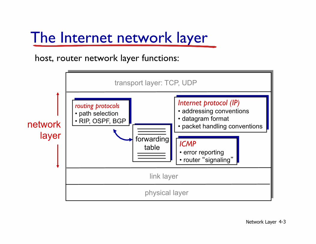
The Internet network layer
forwarding table
host, router network layer functions:
routing protocols • path selection • RIP, OSPF, BGP
Internet protocol (IP) • addressing conventions • datagram format • packet handling conventions
ICMP • error reporting • router “signaling”
transport layer: TCP, UDP
link layer
physical layer
network layer
Network Layer 4-4
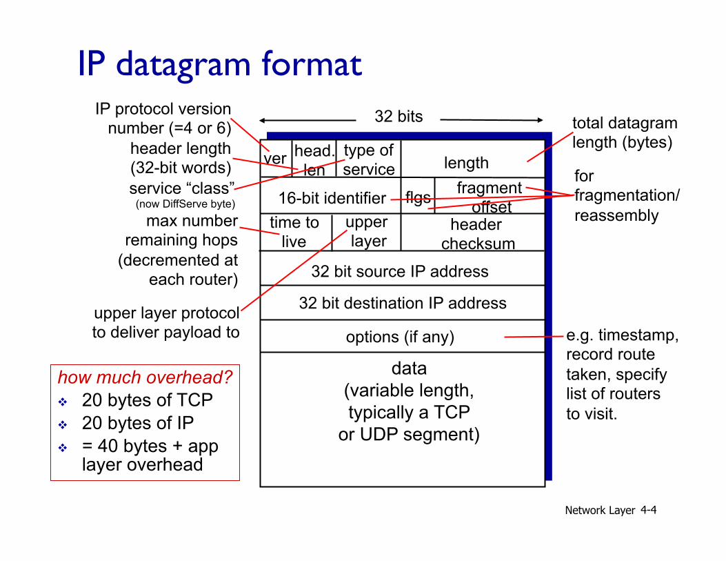
ver length
32 bits
data (variable length, typically a TCP
or UDP segment)
16-bit identifier header
checksum time to
live
32 bit source IP address
head. len
type of service
flgs fragment offset
upper layer
32 bit destination IP address options (if any)
IP datagram format IP protocol version
number (=4 or 6)
header length (32-bit words)
upper layer protocol to deliver payload to
total datagram length (bytes)
service “class” (now DiffServe byte)
for fragmentation/ reassembly max number
remaining hops (decremented at
each router)
e.g. timestamp, record route taken, specify list of routers to visit.
how much overhead? v 20 bytes of TCP v 20 bytes of IP v = 40 bytes + app
layer overhead
Network Layer 4-5
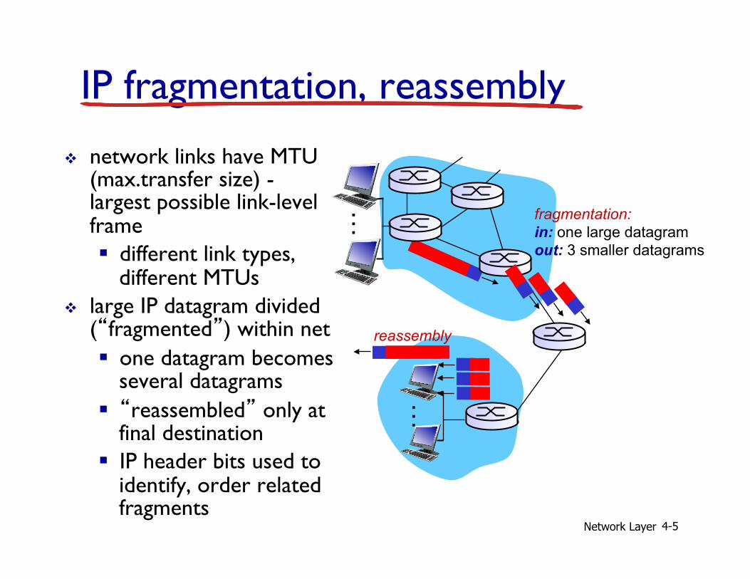
IP fragmentation, reassembly v network links have MTU
(max.transfer size) - largest possible link-level frame § different link types,
different MTUs v large IP datagram divided
(“fragmented”) within net § one datagram becomes
several datagrams § “reassembled” only at
final destination § IP header bits used to
identify, order related fragments
fragmentation: in: one large datagram out: 3 smaller datagrams
reassembly
…
…

Network Layer 4-6
ID =x
offset =0
more =0
length =4000
ID =x
offset =0
more =1
length =1500
ID =x
offset =185
more =1
length =1500
ID =x
offset =370
more =0
length =1060
one large datagram becomes several smaller datagrams
example: v 4000 byte datagram v MTU = 1500 bytes
1480 bytes in data field + 20 byte header
offset = 1480/8
IP fragmentation, reassembly
unit: 8 bytes (64 bits)

Exercise
v Given a datagram with total length (header included) 10,754 bytes and channel MTU = 2048 bytes, how many fragments, and what do their “frag fields” contain?
v How many bytes of data per fragment? • largest d such that 8×d + 20 ≤ 2048 • d = 8×floor(2028/8) = 8×floor(253.5) = 2024 bytes
v How many fragments? • smallest n such that 2024×n ≥ 10,754 • n = ceil(10754/2024) = ceil(5.31) = 6
Network Layer 4-7

Network Layer 4-8
4.1 introduction 4.2 virtual circuit and
datagram networks 4.3 what’s inside a router 4.4 IP: Internet Protocol
§ datagram format § IPv4 addressing § ICMP § IPv6
4.5 routing algorithms § link state § distance vector § hierarchical routing
4.6 routing in the Internet § RIP § OSPF § BGP
4.7 broadcast and multicast routing
Chapter 4: outline

Network Layer 4-9
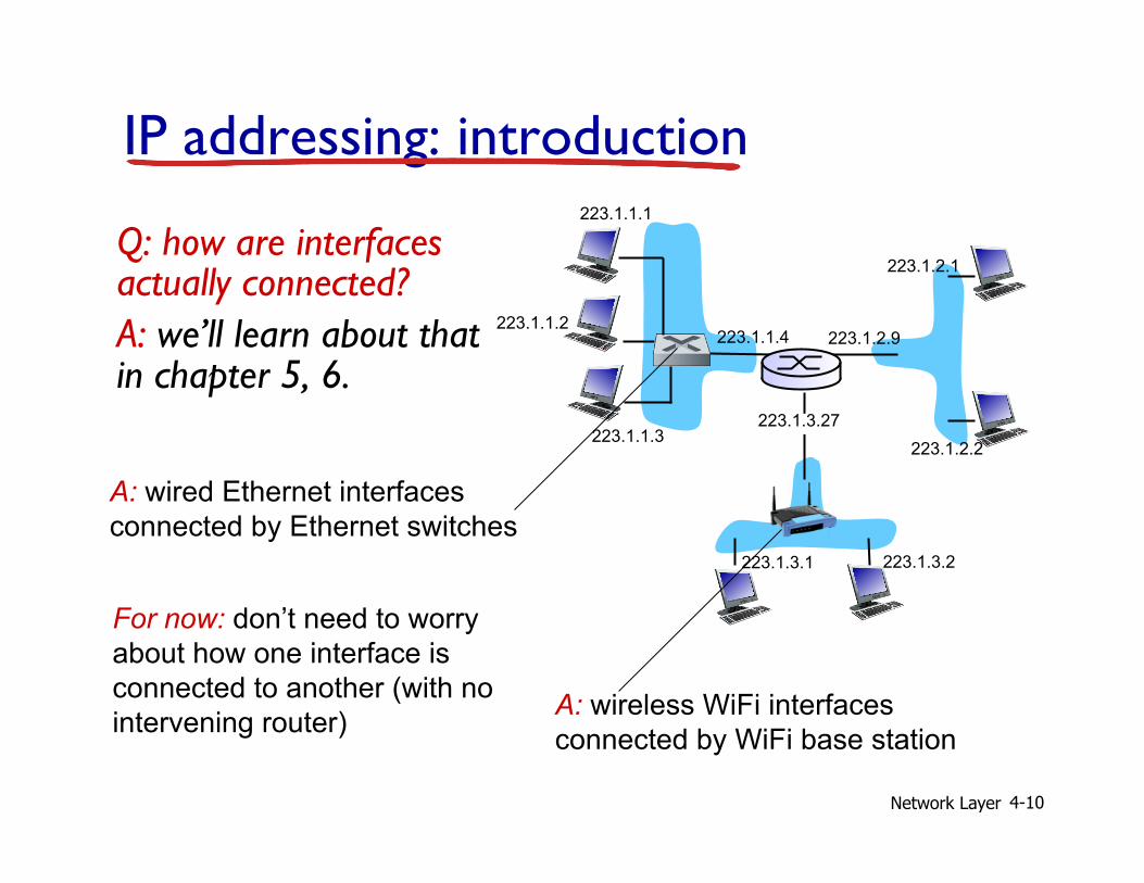
IP addressing: introduction
v IP address: 32-bit identifier for host, router interface
v interface: connection between host/router and physical link § router’s typically have
multiple interfaces § host typically has one or
two interfaces (e.g., wired Ethernet, wireless 802.11)
v IP addresses associated with each interface
223.1.1.1
223.1.1.2
223.1.1.3
223.1.1.4 223.1.2.9
223.1.2.2
223.1.2.1
223.1.3.2 223.1.3.1
223.1.3.27
223.1.1.1 = 11011111 00000001 00000001 00000001
223 1 1 1
Network Layer 4-10
IP addressing: introduction
Q: how are interfaces actually connected? A: we’ll learn about that in chapter 5, 6.
223.1.1.1
223.1.1.2
223.1.1.3
223.1.1.4 223.1.2.9
223.1.2.2
223.1.2.1
223.1.3.2 223.1.3.1
223.1.3.27
A: wired Ethernet interfaces connected by Ethernet switches
A: wireless WiFi interfaces connected by WiFi base station
For now: don’t need to worry about how one interface is connected to another (with no intervening router)

Network Layer 4-11
Subnets
v IP address: § subnet part - high order bits
§ host part - low order bits
v what’s a subnet ? § device interfaces with same subnet part of IP address
§ can physically reach each other without intervening router network consisting of 3 subnets
223.1.1.1
223.1.1.3
223.1.1.4 223.1.2.9
223.1.3.2 223.1.3.1
subnet
223.1.1.2
223.1.3.27 223.1.2.2
223.1.2.1
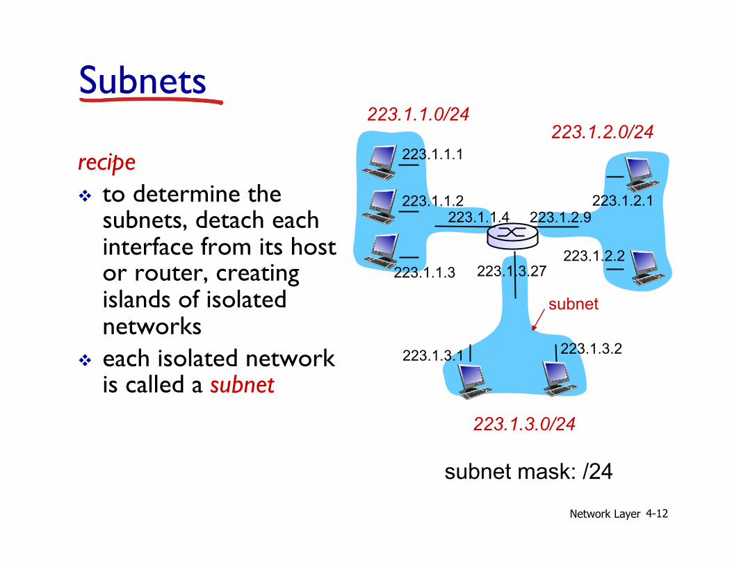
Network Layer 4-12
recipe v to determine the
subnets, detach each interface from its host or router, creating islands of isolated networks
v each isolated network is called a subnet
subnet mask: /24
Subnets 223.1.1.0/24
223.1.2.0/24
223.1.3.0/24
223.1.1.1
223.1.1.3
223.1.1.4 223.1.2.9
223.1.3.2 223.1.3.1
subnet
223.1.1.2
223.1.3.27 223.1.2.2
223.1.2.1

Network Layer 4-13
how many? 223.1.1.1
223.1.1.3
223.1.1.4
223.1.2.2 223.1.2.1
223.1.2.6
223.1.3.2 223.1.3.1
223.1.3.27
223.1.1.2
223.1.7.0
223.1.7.1 223.1.8.0 223.1.8.1
223.1.9.1
223.1.9.2
Subnets