chapter 4.2: flow across a tube bundle heat exchanger (tube bank)
TRANSCRIPT
Chapter 4.2: Flow Across a Tube BundleHeat Exchanger (Tube Bank)

Heat transfer to or from a bank (bundle) of tubes in cross flow is found in many industrial applications, such as steam generator in a boiler or air cooling in the coil of an air conditioner. The geometric arrangement is shown in the figure. One fluid moves over the tubes, while a second fluid passes throughthe tubes.The tube rows of a bank are eitherstaggered or in-line (aligned) in the direction of the fluid velocity (V).The configuration is characterized by 1) The tube diameter (D).2) The transverse (normal) pitch (ST).
3) The longitudinal (parallel) pitch (SL).
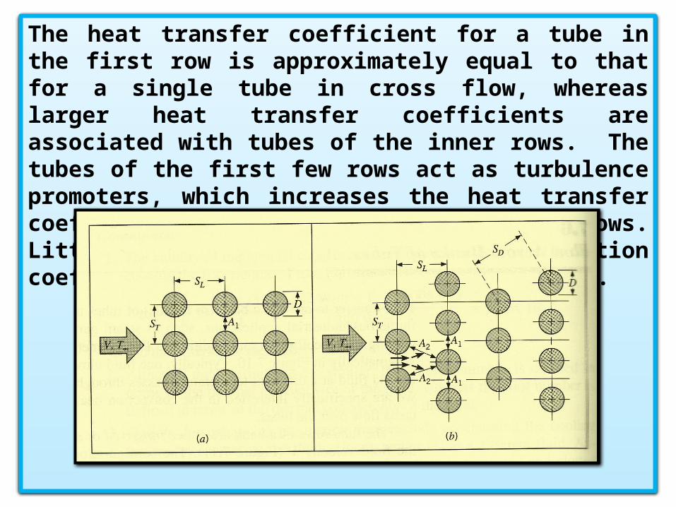
The heat transfer coefficient for a tube in the first row is approximately equal to that for a single tube in cross flow, whereas larger heat transfer coefficients are associated with tubes of the inner rows. The tubes of the first few rows act as turbulence promoters, which increases the heat transfer coefficient for tubes in the following rows. Little change occurs in the convection coefficient for tubes beyond the fifth row.
Tube arrangement in a bank. (a) Aligned. (b) Staggered.
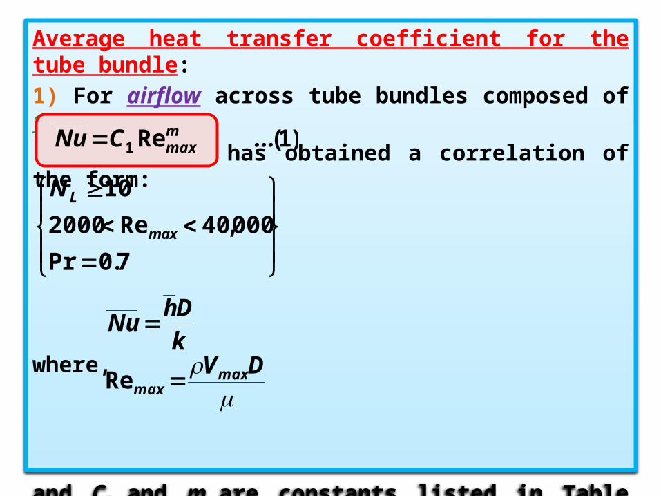
Average heat transfer coefficient for the tube bundle:1) For airflow across tube bundles composed of 10 or more rows, Grimison has obtained a correlation of the form:
where,
and C1 and m are constants listed in Table (1):
)1(Re1 ... CNu mmax
7.0Pr
000,40Re2000
10
max
LN
kDh
Nu
DVmax
max Re
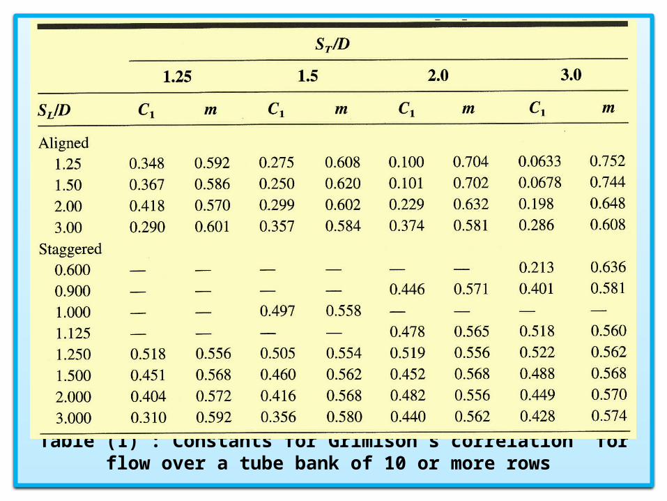
Table (1) : Constants for Grimison’s correlation for flow over a tube bank of 10 or more rows

2) For other fluids flow across tube bundles composed of 10 or more rows, the average Nusselt number becomes
All properties appearing in the above equations are evaluated at the film temperature, where
3) For flow across tube bundles composed of number of rows less than 10 (NL < 10), a correction factor C2 may be applied such
that
)2(PrRe13.1 311 ... C Nu m
max
7.0Pr
000,40Re2000
10
max
LN
2w
f
TTT
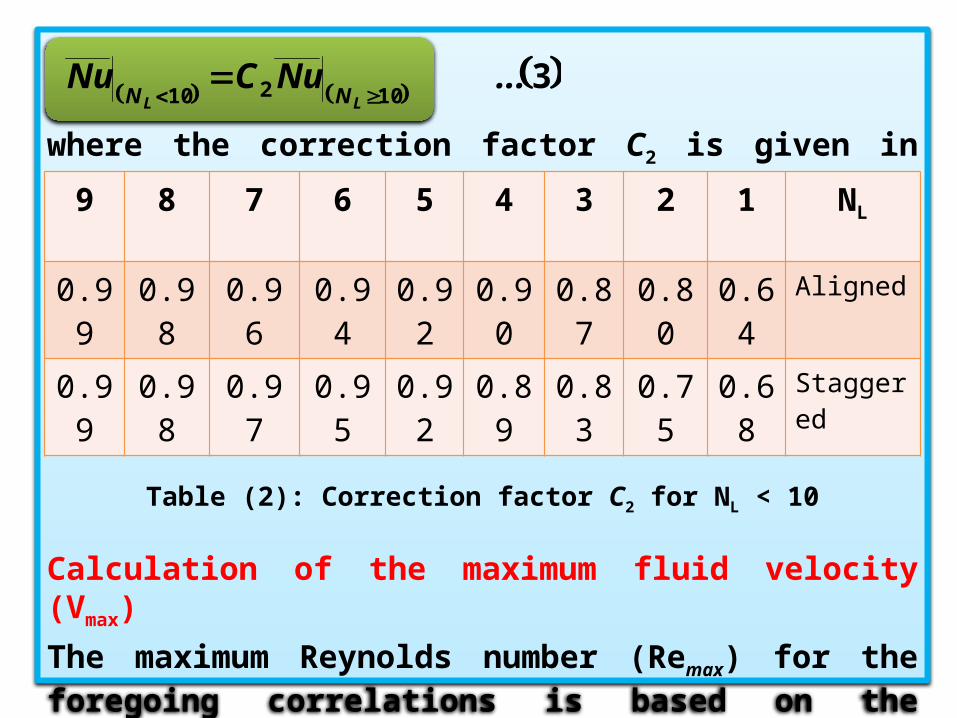
where the correction factor C2 is given in Table (2):
Table (2): Correction factor C2 for NL < 10
Calculation of the maximum fluid velocity (Vmax)
The maximum Reynolds number (Remax) for the foregoing correlations is based on the maximum fluid velocity (Vmax) occurring within the tube bank.
310210
... NuCNuLL NN
9 8 7 6 5 4 3 2 1 NL
0.99
0.98 0.96 0.94 0.92
0.90 0.87
0.80 0.64
Aligned
0.99
0.98 0.97 0.95 0.92
0.89 0.83
0.75 0.68
Staggered

Case of aligned (in-line) arrangement: The maximum velocity occurs at the transverse plane A1.From the continuity
equation (mass conservation)
V = inlet velocity = incoming flow velocity = free stream velocity
Case of staggered arrangement:The maximum velocity may occur at either the transverse plane A1 or the diagonal plane A2.
VAm .
DSVSV TmaxT 1
V DS
SV
T
Tmax
21
21
DSDSA TT
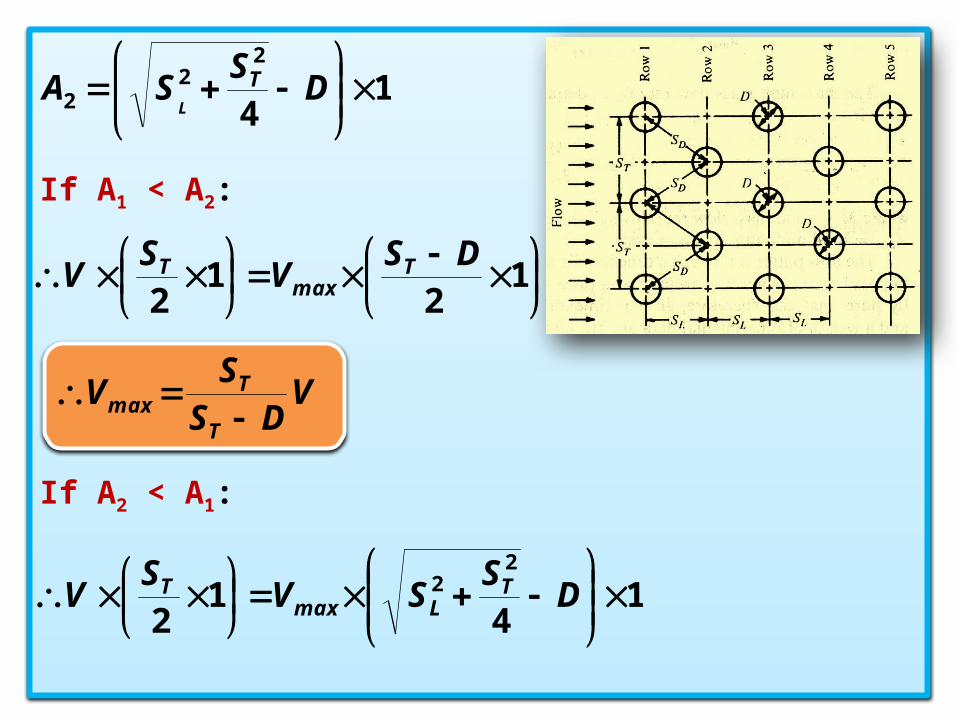
If A1 < A2:
If A2 < A1:
14
22
2
D
SSA T
L
1
21
2DS
VS
V Tmax
T
V DS
SV
T
Tmax
14
12
22
D
SSV
SV T
LmaxT
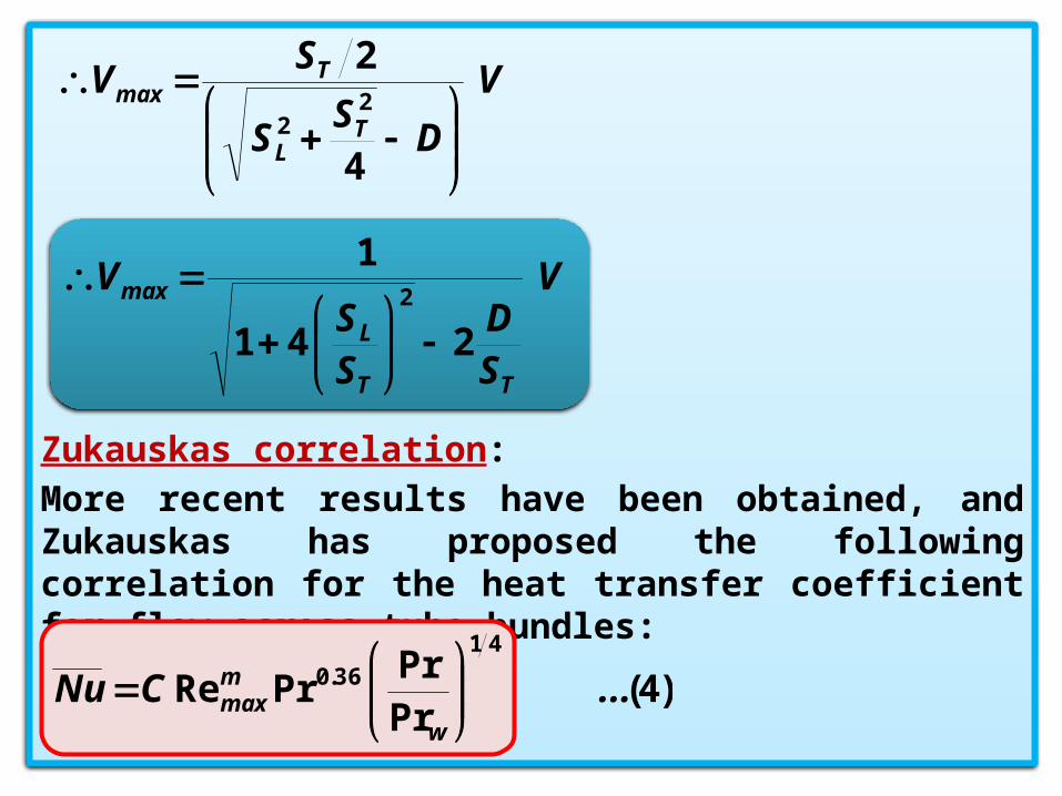
Zukauskas correlation:
More recent results have been obtained, and Zukauskas has proposed the following correlation for the heat transfer coefficient for flow across tube bundles:
V
DS
S
SV
TL
Tmax
4
22
2
V
SD
SS
V
TT
L
max
241
12
)4(PrPr
PrRe41
36.0 ... C Nuw
mmax
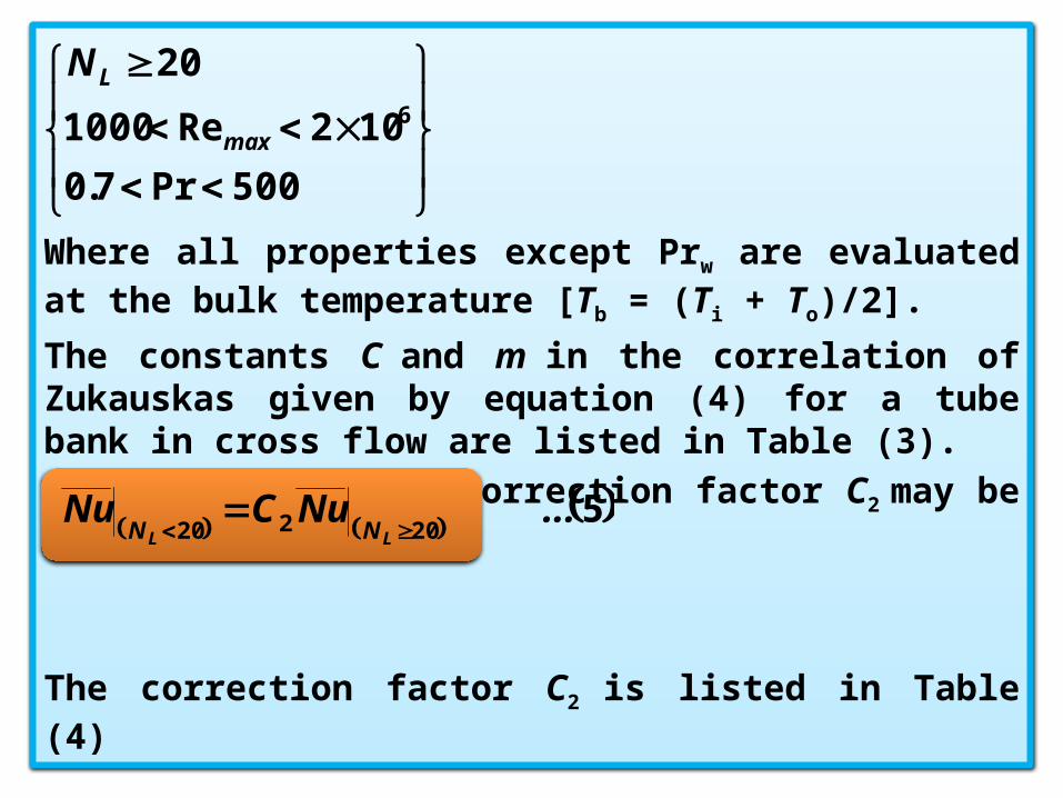
Where all properties except Prw are evaluated at the bulk temperature [Tb = (Ti + To)/2].
The constants C and m in the correlation of Zukauskas given by equation (4) for a tube bank in cross flow are listed in Table (3).If NL < 20 rows, a correction factor C2 may be applied such that
The correction factor C2 is listed in Table (4)
500Pr7.0
102Re1000
206
max
LN
520220
... NuCNuLL NN

Table (3): The constants C and m in the correlation of Zukauskas

Table (4): Correction factor C2 for NL < 20 , Re > 103
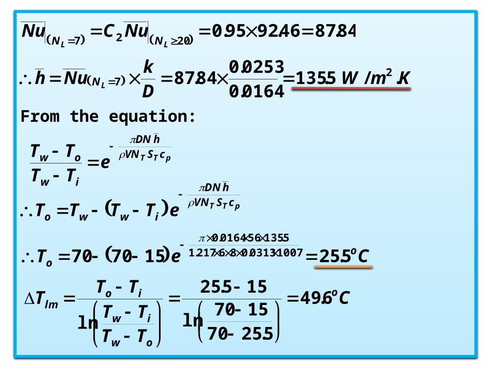
Logarithmic Mean Temperature Difference:
where Ti and To are temperatures of the fluid as it enters and leaves the bank, respectively.
16 13 10 7 5 4 3 2 1 NL
0.99
0.98 0.97 0.95 0.92
0.90 0.86
0.80 0.70
Aligned
0.99
0.98 0.97 0.95 0.92
0.89 0.84
0.76 0.64
Staggered
ow
iw
io
ow
iw
owiwlm
TTTT
TT
TTTT
TTTTT
lnln

Calculation of the outlet temperature (To):
The outlet temperature, which is needed to determine Tlm , may be estimated from
N = total number of tubes in the bankNT = number of tubes in the transverse plane (normal to the flow)
Calculation of the heat transfer rate (Q):
The heat transfer rate from the bank of tubes may be computed from
pTT cSVNhDN
iw
ow eTTTT
lmlmtubetube T DL hTAhQ .
lmbank T DL hNQ .
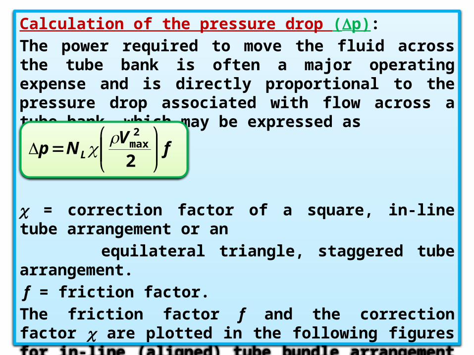
Calculation of the pressure drop (p):
The power required to move the fluid across the tube bank is often a major operating expense and is directly proportional to the pressure drop associated with flow across a tube bank, which may be expressed as
= correction factor of a square, in-line tube arrangement or an equilateral triangle, staggered tube arrangement. f = friction factor.The friction factor f and the correction factor are plotted in the following figures for in-line (aligned) tube bundle arrangement as well as for staggered tube bundle arrangement.
fV
Np L
2
2max
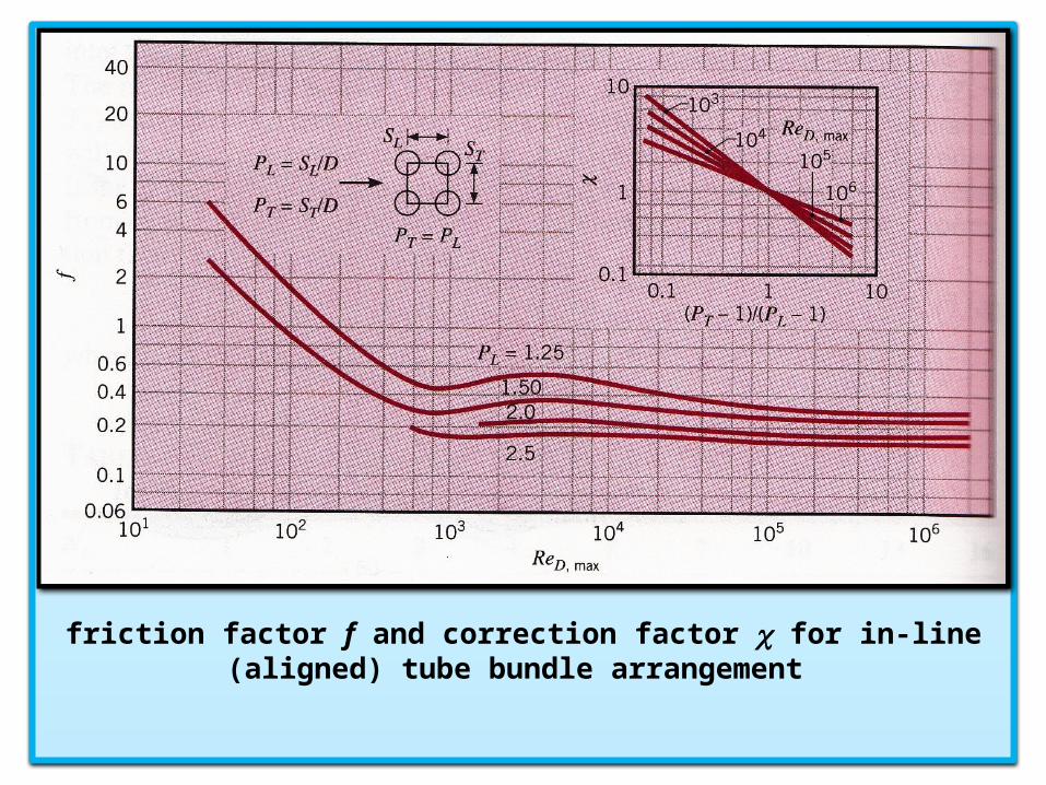
friction factor f and correction factor for in-line (aligned) tube bundle arrangement
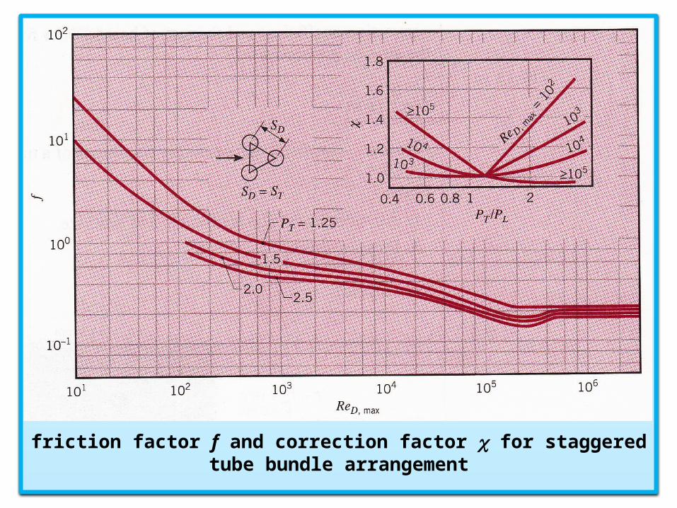
friction factor f and correction factor for staggered tube bundle arrangement

Example:
Pressurized water is used for space heating or industrial process applications. In such cases it is customary to use a tube bundle heat exchanger in which the water is passed through the tubes, while air is passed in cross flow over the tubes. Consider a staggered arrangement for which the tube outside diameter is 16.4 mm and the longitudinal and transverse pitches are 34.3 mm and 31.3 mm respectively. There are seven rows of tubes in the airflow direction and eight tubes per row. The tube surface temperature is at 70oC, while the air upstream temperature and velocity are 15oC and 6 m/s, respectively. Determine: a) The air-side average heat transfer coefficient (using Zukauskas correlation).b) The air outlet temperature.c) The rate of heat transfer per unit tube length.d) The air-side pressure drop.

Data: Tube bundle, staggered arrangement, D = 16.4 mm, SL = 34.3 mm, ST = 31.3 mm, NL = 7, NT = 8,
Tw = 70oC, T = Ti = 15oC, V = 6 m/s. L = 1 m
Required: a) , b) To , c) , d) p.
Solution: For air at T = Ti = 15oC, = 14.8210-6 m2/s, Pr = 0.71,
k = 0.0253 W/m.K., = 1.217 kg/m3, cp = 1007 J/kg.K.
For air at Tw = 70oC, Pr = 0.701.
For air at Tf = (Tw + Ti )/2 =(70 + 15)/2 = 42.5oC, Pr = 0.705
h bankQ.
231 1045.7
20164.00313.0
2m
DSA T
m
DS
SA TL
232
2
22
2
103.210164.04
0313.00343.0
14

Since A1 < A2 , the maximum velocity occurs on the transverse plane, A1
It follows from the tables that
sm V DS
SV
T
Tmax /6.126
0164.00313.00313.0
943,131082.14
0164.06.12Re 6
DVmax
max
291.00343.00313.0 LT SS
95.06.034.035.0 251 C , m , SSC LT
46.92701.071.0
71.0943,1334.0
PrPr
PrRe
25.036.06.0
41
36.020
C Nuw
mmaxN L
From the equation:
84.8746.9295.02027
LL NN
NuCNu
KmW Dk
Nuh LN ./5.1350164.00253.0
84.87 27
pTT cSVNhDN
iw
ow eTTTT
pTT cSVNhDN
iwwo e TTTT
Ce T o
o 5.25157070 10070313.086217.15.135560164.0
C
TTTT
TTT o
ow
iw
iolm 6.49
5.25701570
ln
155.25
ln
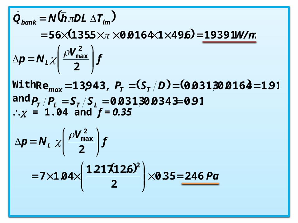
With , and = 1.04 and f = 0.35
W/m
T DL hNQ lmbank
193916.4910164.05.13556
.
fV
Np L
2
2max
91.10164.00313.0943,13Re DSP , TTmax
91.00343.00313.0 LTLT SSPP
Pa
fV
Np L
24635.02
6.12217.104.17
22
2max