chapter 51 pp285-308 krs notations per nash updates of 3-26-08
TRANSCRIPT

CHAPTER
51
51.1 INTRODUCTION
The present code PD 5500, formerly BS 5500 [1], evolved part-ly from the well-known BS 1500 [2] of the 1950s and BS 1515[3] first published in 1965; the latter permitted higher-level allow-able stresses and more advanced rules. In 1969, following a reportfrom the Committee of Enquiry into the Pressure Vessel Industry,the British Standards Institution brought all the pressure vesselinterests together under one general committee to rationalize theactivity. This became PVE/ and presides over a large committeestructure. There are a series of functional subcommittees that dealwith specific aspects, many technical committees, and severalsubcommittees and working groups. Most of these meet regularly.The technical committee PVE/1, Pressure Vessels, has overallresponsibility for BS 5500. The functional committee PVE/1/15Design Methods has an overall responsibility relating to design,with particular reference to the design section of BS 5500(Section 3).
The first edition of BS 5500 was issued in 1976. The issue wasdelayed for some time because, in the early 1970s, there was anattempt in Europe to produce an international pressure vesselstandard. A draft of the international standard appeared as ISODIS 2694 [4] in 1973, but it was not generally accepted and theattempt was abandoned in the mid-1970s. It was decided to usesome of the material from 2694 within BS 5500 so that, althoughthe Standard was delayed, it benefited to some extent from theinternational efforts. Initially, committee PVE/l set out the con-cept of a “master” pressure vessel standard that could readily beapplied to any vessel in either ferrous or nonferrous materials andfor highly specialized application with the minimum of supple-mentary requirements. The layout of BS 5500 is consistent withthis concept and, although the Standard has perhaps not fulfilledthis high ideal, it has certainly been employed widely in manyindustries including nonpressure-vessel-type applications. Whenissued, it had several distinctive features compared with otherpressure codes, such as the following: weld joint factors wereremoved, the present three categories of construction were intro-duced, there was a new novel external pressure section, it had aloose-leaf format, and an annual updating was introduced.Revised editions of BS 5500 have been issued every 3 years since1982.
51.1.1 Withdrawal of BS 5500 and Issuance of PD5500
In May 2002, the first issue of the European Standard EN13445, Unfired Pressure Vessels [5] was published. This standardhas been developed to facilitate the provision of vessels subject tothe European pressure equipment directive (PED) 97.23.EC [6].Under the CEN rules, BSI was obliged to withdraw BS 5500when the European Standard was published in 2002.
The first edition of EN 13445 was not as comprehensive as BS5500, and due to demands from industry it was decided that theBritish pressure vessel standard should continue to be availableand become a published document (PD) under the new designa-tion, PD 5500, with equal content, validity, and application to theprevious BS 5500. Its principle difference is that it does not havethe status of a national standard.
It should be noted that most other European pressure vesselcodes are not national standards (i.e., they are not published bythe national standards body of the country in which they apply).
51.1.2 The PED and PD 5500The main provisions of the PED are summarized, and are cov-
ered in detail in Chapter 47.The PED is what is termed a “new approach’’ directive, which
prescribes essential safety requirements (ESRs) that are intendedto maintain existing safety levels within the EuropeanCommunity.
The European Parliament and the Council of Ministersapproved the PED in May 1997. All member states were requiredto introduce national laws and provisions necessary to complywith the PED by November 29, 1999. A transition period appliedthrough to May 29, 2002, when the directive became fullyenforced. With its advent, member states must not permit theplacing on the market of pressure equipment or assemblies that donot comply with the regulations in force.
To implement the requirements of the PED in the UK, theDepartment of Trade and Industry (DTI) published the PressureEquipment Regulations 1999 (SI 1999/2001) [7], which becamelaw in February 2000. The DTI has also produced a free guidancebooklet URN 99/1147. The Health & Safety Executive is respon-sible for the enforcement of the legislation in the UK.
UK RULES FOR UNFIRED
PRESSURE VESSELS
David H. Nash
286 • Chapter 51
The Pressure Systems and Transportable Gas ContainerRegulations 1989 have been revoked and are replaced by thePressure Systems Safety Regulations 2000 (SI 2000/128), whichapply to the design and construction of pressure equipment notcovered by the Pressure Equipment Regulations and to the useand ongoing integrity of pressure systems.
The PED applies to products that are first placed on the mar-ket/put into service/supplied in any EU member state and appliesto equipment produced for the home market as well as for prod-ucts destined for use in other EU countries. It also applies to prod-ucts imported from outside the EU.
The PED covers the design, manufacture, and conformityassessment of pressure equipment and assemblies with a maxi-mum allowable pressure greater than 0.5 barg. The PED does notapply to modifications, servicing, and repair of equipment unlessthere is a substantial change of use.
(a) Pressure equipment includes the following components:
(1) pressure vessels: housings designed and built to containfluids under pressure.
(2) piping: piping components intended for the transport offluids when connected together for integration into apressure system.
(3) safety accessories: devices designed to protect pressureequipment against the allowable limits being exceeded.
(4) pressure accessories: devices with an operational func-tion and having pressure bearing housings.
In general, the duties fall on the manufacturer, but care isneeded in determining who the manufacturer is (it is not neces-sarily the fabricator). Duties may also fall to a designer, animporter, a user, a supplier, or the manufacturer’s authorizedrepresentative.
Each item of equipment is classified into one of the four con-formity assessment categories (I to IV) according to the tablesin Annex II of the PED, or as sound engineering practice (SEP)for very low risk equipment. The classification depends on thetype of equipment (vessel, steam generator, or piping), the stateof the fluid contents (gas or liquid), the fluid group of theintended contents (group 1 or 2), and the pressure/volume ofthe equipment.
Fluid Group 1 consists of those fluids classified, according tothe EC Directive on the classification of dangerous substances(Directive 67/548/EEC of 27 June 1967), as explosive, extremelyflammable, highly flammable, flammable, very toxic, toxic, oroxidizing. Group 2 consists of all other fluids including steam.
The pressure/volume of the equipment is the design pressure inbars multiplied by the volume in liters, or for piping, the pressuremultiplied by the nominal size in millimeters.
Equipment classified as SEP must be designed and manufacturedaccordingly. CE marking must not be affixed to SEP equipment.
For equipment classified in categories I to IV, the technicalrequirements of the PED are presented as a set of basic princi-ples, the ESRs, which have to be met. Article 3 and Annex I ofthe PED state the Technical Requirements and the ESRs,respectively.
The ESRs cover general requirements, design, manufacturing,and materials. The use of the European harmonized standardsbeing developed, such as EN 13445 on unfired pressure vessels,confers a presumption of conformity to the ESRs. PD 5500Annex Z gives guidance on the application of PD 5500 to pres-sure vessels falling within the scope of the PED.
To demonstrate that the ESRs are satisfied, the PED requiresequipment to be subjected to conformity assessment procedures.The conformity assessment modules have been designed to reflectcurrent industrial practice, and manufacturers are given a choiceof modules depending on the category.
Equipment in Category I is subject to the manufacturer’s owninternal production control. The modules for products inCategories II, III, and IV require the involvement of notified bod-ies appointed by Member States, either in the approval and moni-toring of the manufacturers’ quality assurance system or in directproduct inspection.
In the construction of equipment, materials used that fall withinthe scope of the PED must comply with the directive. For equip-ment that falls within the scope of the PED, the materials mustcomply with the directive.
(b) The following three routes are available to demonstrateconformity with the PED:
(1) by using materials that comply with harmonizedEuropean standards
(2) by using materials covered by a European Approval ofMaterials (EAM)
(3) by a Particular Material Appraisal (PMA)
The EAM approval will be performed by those notified bodiesspecifically appointed for this task. The result of an EAM is aEuropean Data Sheet, which will contain all the necessary infor-mation for the design engineer as well as the inspector. Referenceto the EAM will be published in the Official Journal of theEuropean Communities.
A PMA follows a similar assessment route without subsequentpublication of the information. Materials approved by this routecan only be used by the manufacturer who obtained the approvalon the job concerned. If the same material is used on another jobor by a different manufacturer, then a new approval must beobtained.
Some European materials standards have been published, suchas EN 10028, Flat Products Made of Steels for Pressure Purposes,and EN 10222, Steel Forgings for Pressure Purposes, but many ofthe materials are not yet readily available from stock. Europeanmaterial standards for pipe, tube, and fittings have not yet beenpublished. In many cases, it will be necessary to follow the EAMor PMA routes where harmonized product or material standardsare not yet available, or when the manufacturer wishes to usematerials to BS, ASTM, DIN, or other standards.
Presently, only 15 EAM approvals have been issued, all relat-ing to nickel 201 and nickel alloy materials. The PMA route mustbe used for all other non-European materials.
The PED, Annex I subsection 7.1.2 gives specific requirementsfor the evaluation of allowable stresses. In some cases, theserequirements are more conservative than PD 5500 resulting inlower design stresses. In particular, the allowable stress for ferriticmaterials is limited to the smaller of Re/1.5 or Rm/2.4 (see whereRe is the yield strength and Rm is the ultimate tensile strength).The safety factor of 2.4 for the tensile strength is slightly higherthan the value of 2.35 used to derive the design strengths for fer-ritic materials in PD 5500, Tables K.1-2 to K.1-12. For equipmentthat must comply with the PED, the design strength at ambienttemperature may need to be reduced accordingly. For example,the design strength to the PED for BS 1501-224-490A or 490Bmaterial at 50°C would be 204.17 N/mm2 compared with 208.0N/mm2 from PD 5500, Table K.1-2.

COMPANION GUIDE TO THE ASME BOILER & PRESSURE VESSEL CODE • 287
Similarly, the allowable stress to the PED for austenitic stain-less steels, where the elongation after rupture exceeds 35%, islimited to the smaller of Re/1.2 or Rm/t/3.0. Generally, this onlyaffects the S61 and S63 grades. Rm/t is the tensile strength at thedesign temperature. These data are not generally available for BSmaterials, but, for ASME/ASTM materials, values are given inASME BPVC Section II, Part D, Table U. For example, thedesign strength to the PED for BS 1501-304-S61 material at 50°Cwould be 183.33 N/mm2 compared with 203.0 N/mm2 from PD5500, Table K.1-4.
For equipment manufactured from carbon steel that must com-ply with the PED, the factor for Rm should be increased from 2.35to 2.4. For equipment manufactured from austenitic stainless steelthat must comply with the PED, the factor for Rm for austeniticstainless steels where the elongation after rupture exceeds 35%,should be increased from 2.5 to 3.0. In the PED, Rm should strictlybe Rm/t (the tensile strength at the design temperature), but thesedata are often not available. Most austenitic plate materials to BS1501 Part 3 or ASTM A 240 have a specified elongation thatexceeds 35%.
For austenitic stainless steels where the elongation after ruptureexceeds 30% but does not exceed 35%, the design strength to thePED is limited to at all temperatures, but is not affected byRm. Many austenitic stainless steel forging materials have a speci-fied elongation that does not exceed 35%.
For equipment that must comply with the PED, the designstrength for aluminium alloys, excluding precipitation hardeningalloys, is the smaller of Rp0.2/1.5 or Rm/2.4.
51.2 PD 5500
PD 5500 specifies requirements for the design, construction,inspection, testing, and verification of compliance of unfiredfusion-welded pressure vessels. The responsibilities of the pur-chaser, the manufacturer, and the Inspecting Authority are definedin subsection 1.4. On completion of the vessel, the manufacturermust issue “Form X” to certify that the vessel has been designed,constructed, and tested in accordance with PD 5500 and with anyadditional requirements specified by the purchaser.
Vessels that are required to comply with the PED must also beaccompanied by a Declaration of Conformity and, where relevant,operating instructions.
(a) PD 5500 covers five basic material types as follows:
(1) ferritic steels such as carbon, carbon manganese, andlow alloy steels
(2) austenitic steels such as types 304, 316, 321, and 347stainless steels
(3) aluminium and aluminium alloy(4) nickel and nickel alloys(5) copper and copper alloys
Although other nonferrous materials are not specificallycovered by PD 5500, the code is quite commonly used fordesigning vessels in other materials. Requirements for tita-nium will be published as an Enquiry Case.
For equipment that falls within the scope of the PED thematerials must comply with the directive.
(b) Certain special types of vessel are covered by specific stan-dards as follows:
(1) BS 1113 for water-tube steam generating plant (partiallyreplaced by BS EN 12952)
23 Re(T)
(2) BS 2790 for shell boilers of welded construction (par-tially replaced by BS EN 12953)
(3) BS 4975 for prestressed concrete pressure vessels fornuclear engineering
(4) BS 4994 for vessels and tanks in reinforced plastics(5) BS 5169 for fusion-welded steel air receivers (excluding
those vessels covered by BS EN 286)(6) BS 7005 for carbon steel vessels for use in vapor com-
pression refrigeration systems(7) BS EN 286 for simple unfired pressure vessels designed
to contain air or nitrogen (Parts 1 to 4)
(c) Other vessels not covered by the above standards wouldnormally be designed to PD 5500, Specification for UnfiredFusion Welded Pressure Vessels. This standard is dividedinto five sections together with various appendices andCode enquiry cases as follows:
(1) Section 1, General(2) Section 2, Materials(3) Section 3, Design(4) Section 4, Manufacture and Workmanship(5) Section 5, Inspection and Testing
(d) There are also several other documents published by BSIthat give background information relating to the require-ments of PD 5500, including the following:
(1) PD 6439 is a review of the methods of calculating stress-es due to local loads and local attachments of pressurevessels.
(2) PD 6497 gives stresses in horizontal cylindrical pressurevessels supported on twin saddles, a derivation of thebasic equations and constants.
(3) PD 6550 is an explanatory supplement to BS 5500:1988that includes the following:
(a) Part 1, domed ends (heads)(b) Part 2, openings and branch connections(c) Part 3, vessels under external pressure(d) Part 4, heat exchanger tubesheets
51.2.1 MaterialsThe basic material type to be used will normally be specified
by the process engineer, often in conjunction with a metallur-gist. Typical factors that might affect this selection are the corro-sion resistance; the presence of aggressive contents such ashydrogen sulphide, hydrogen, and chlorides; exposure to highand low temperatures; cost; and weight. While selecting thematerial type, the process engineer will also consider what cor-rosion allowance should be applied. The purchaser and the man-ufacturer shall give joint consideration to the likely effect thatcorrosion (internal and external) will have on the useful life ofthe vessel (Section 3.3.1).
From the basic material type, the specific material grades forthe various components of the vessel are chosen. These materialgrades or specifications are selected from British Standards, suchas BS 1501 and BS 1503, or European Standards, such as BS EN10028, or other national standards such as ASME BPVC SectionII or ASTM. It is noted that many British Standards, such as BS1501 and BS 1503, have been superseded by European Standards;but, materials to these superseded standards are still available.
The material design strength is usually established from thebasic material properties of yield strength and ultimate tensile

288 • Chapter 51
strength (UTS). For carbon steels, for example, the nominaldesign strength, fE, is established as the lower of the following:
These factors on yield and UTS are essentially those proposedin ISO/DIS 2694 [4]. If the material is operated at temperature,then suitable reductions in strength are enforced. Where a materi-al testing standard specifies 0.2% or 1.0% proof stress, these val-ues are taken as Re. Using this basis for establishing the designstrength, values are tabulated in Annex K for various productforms and vary according to thickness and temperature. If thedesign temperature is in the creep range, the calculation of stresslevels can be complex and so, for membrane regions, the stresslimit is set to be less than the creep rupture stress/1.3. Tabulateddesign strength values at high temperature are also provided andvary according to length of time in hours at elevated temperature.
For carbon steel vessels operating at low temperature, resis-tance to brittle fracture is addressed by ensuring that the materialhas sufficient toughness. Consideration is given to the level ofmembrane stress, the level of inspection, and also the use of post-weld heat treatment, which are seen as adjustments to the basicdesign temperature. The procedure makes sure that the material atthe appropriate thickness has sufficient ductility at room tempera-ture. If, however, it does not, then the method provides the lowtemperature value to which material must be tested. Using aCharpy V-Notch test, for most carbon steels an impact energyvalue of 27 J must be achieved using a 10 � 10 mm specimen.For high-strength steels, 40 J must be achieved. Austenitic stain-less steels and aluminium alloys are not susceptible to low-stressbrittle fracture, so no special requirements are necessary for theiruse at temperatures down to �196°C.
PD 5500 has little to say on the strength of welds. It is consid-ered that the weld process controls the quality and that weldingstandards EN 287 [8] and 288 [9] ensure that the weld proceduresand welder approval affirm that the strength and ductility is com-patible with the parent material. This implies the joint efficiencyfactor is equal to unity.
51.2.2 DesignSection 3 of PD 5500 contains specific rules for performing
calculations for shells, heads, cones, nozzles, flat covers, flanges,and tubesheets. Most methods in this section are design-by-rule,and minimum thicknesses can be calculated if the leading dimen-sions, allowable strength, and design pressure are known. Theseare well-established rules and have much in common with themajor international pressure vessel codes. As such, only a briefpresentation of the methods is made and differences with othercodes are highlighted where appropriate.
51.2.3 Shells Under Internal Pressure
(a) Cylinders and Spheres. PD 5500 allows the design of thinshells under internal pressure loading using membranestress analysis. Thick-walled pressure vessels are normallyanalyzed using the Lame equations. Design equationsbased on this analysis are given in ASME BPVC SectionVIII, Division 1, Appendix 1 [10]. Thin cylindrical shellsare treated as a closed-end cylindrical shell under internalpressure, and the stresses can be found from the conditionsof static equilibrium and by evaluating the governing hoop
fE �Re
1.5 or
Rm
2.35
stress. Rearranging the equation as per subsection3.5.1.2(a) allows the thickness to be evaluated. In the caseof spherical shells, a similar set of equations is given insubsection 3.5.1.2(b). These are approximately based onLame’s equations and incorporate a safety factor, whichmeans that the pressure term has a multiplier.
for cylindrical shells and for
spherical shells
(b) Dished Ends. Dished ends follow a pattern similar to thatof spherical ends. However, fabrication of hemisphericalends (and spherical vessels) is expensive, normally using alabor-intensive cap-and-petal method. The most commonlyused closures for pressure vessels are torispherical andellipsoidal dished ends. Ellipsoidal ends are usually speci-fied as 2:1 (the ratio of major to minor axes), but otherratios may be used. A torispherical end consists of a spheri-cal portion (the crown) and a toroidal portion (the knuckle).This type of end is normally made from a disc, which isheld at the center and spun and cold-formed into thedesired shape. Torispherical ends generally have a crownradius of between 80% and 100% of the shell diameter anda knuckle radius of between 6% and 15% of the diameter.
Such heads are prone to buckling under internal pressure;subsection 3.5.2.2 makes recommendations limiting theshape of the end to prevent this from occurring. A compos-ite graph is available that is based on a stress concentrationfactor along with limit pressure data and allows the mini-mum thickness to be evaluated as a function of headheight, design pressure, and design stress. Recent FE elas-tic-plastic work [11] has influenced the design procedure,and this has been incorporated along with the PD 5500approach into EN 13445-3.
(c) Conical Shells. Where a vessel has sections with differentdiameters, these are usually joined by means of a conicalsection. Conical ends are sometimes used in place ofdished ends, particularly when the end has a large centralnozzle. The rules note that the design of nozzle reinforce-ment for dished ends is limited in clause 3.5.4.2(d) to noz-zle diameters not exceeding one half of the diameter of theequivalent sphere for the crown portion of the end. Forlarger nozzles, a conical end would be used. Knuckles maybe provided at the large and small ends of cones. In addi-tion to calculating the maximum required thickness of thecone for internal pressure, the reinforcement of the cone tocylinder junctions at the large and small ends must bechecked to ensure that the discontinuity stresses at the junc-tion are acceptable. Although it is possible to analyze thesediscontinuity stresses, the method in PD 5500 section 3.5.3contains a simplified calculation for the reinforcement.
In the January 1996 amendments, the design method for thereinforcement of cones was completely revised. The newmethod has its origins in the TGL standards [12] from the for-mer East Germany and is very similar to the method in BSEN 13445-3 sub-section 7.6. The method is based on a limitanalysis, and some supporting information is given in thebackground to the rules in EN 13445-3 [5]. The rule is cast inthe form of establishing the thickness based on pressure load-ing and taking the effect of the discontinuity like a stress con-centration factor � (see Fig. 51.1).
e �pDi
4f � 1.2pe �
pDi
2f � p

COMPANION GUIDE TO THE ASME BOILER & PRESSURE VESSEL CODE • 289
where
The reinforcement must not be reduced near the disconti-nuity for a distance of the form . This is typical ofa “die-out’’ distance from shell theory.
For vessels subject to combined loading, PD 5500 does notprovide explicit equations for the minimum thickness for cylindri-cal, spherical, and conical shells subjected to loads in addition tothat of internal pressure, so a trial-and-error solution is necessary(see PD 5500 Annex B).
A first approximation for the required thickness for cylindricalshells subject to an axial load W and a bending moment M is out-lined in subsection 3.5.1.3.2. When this approximate analysisindicates that an increase in thickness is required, then Annex Bshould be use to determine the minimum thickness.
51.2.4 Shells Under External PressureBeyond internal pressure loading, covered in the previous section,
many vessels are also subject to external pressure. This may be dueto a vacuum condition inside the vessel or an applied external pres-sure as occurs for the inner shell of a jacketed vessel. The design ofexternally pressurized vessels involves a completely differentapproach from that used for internally pressurized vessels. In addi-tion to analyzing the compressive membrane stresses, the problemsof elastic and plastic buckling must be considered. A detailed dis-cussion of the theory involved is given in PD 6550: Part 3 [13].
When analyzing a cylindrical shell subject to external pressure,it is not possible to calculate the required shell thickness directly.The procedure in PD 5500 enables an allowable external pressureto be calculated for a given shell diameter, length, and thickness.Because the allowable external pressure reduces as the shelllength is increased, it is often necessary to use ring stiffeners toproduce an efficient design. An efficient design is one that mini-mizes the shell thickness and, as such, must have a short maxi-mum length between any two stiffening planes.
Shape imperfections are also of importance because these willnormally increase under the action of external pressure. The cal-
l � √De
� �1
3 √ Dc
ej�
tan�
1 � 1� √cos�� 0.15ej �
pDc�
2f
culations in PD 5500 Section 3.6.1 are valid for cylindrical shellsthat are circular to within 0.5% on the radius. A procedure tomeasure and calculate the departure from a true circle is given inclause 3.6.8. A method is given in Annex M for the determinationof the safe external working pressure for cylindrical shells outsidethis circularity limit.
In the design of stiffened cylindrical shells, the following threeconditions are considered:
(a) Interstiffener buckling is the local collapse of the shellwhile the stiffeners remaining circular; this generallyoccurs when the stiffeners are placed too far apart.
(b) Overall buckling of the shell is the general gross collapseof the shell and any stiffeners that are attached; this gener-ally occurs when the stiffeners are too weak to resist theexternal pressure.
(c) Stiffener instability is the local buckling of the stiffener thatmay result in an overall shell buckling situation; this gener-ally occurs when the stiffener proportions are incorrect,namely, tall, thin stiffeners in which the individual websmay initially collapse.
The interstiffener buckling check must be performed for allcylindrical shells subject to external pressure. The overall buck-ling and stiffener instability checks are only performed whenadditional stiffeners are introduced (see Fig. 51.2).
The design procedure allows the determination of two impor-tant pressure quantities. The first is the pressure, py, at which themean circumferential stress in the cylindrical shell midwaybetween stiffeners reaches the yield point of the material, fromEq. (3.6.2-7), as follows:
where
s � a material factor (1.1 for austenitic steels and 1.4 for car-bon steels)
f � the design strength
py �sfe
R(1 � G)
FIG. 51.1 VALUES OF COEFFICIENT � FOR CONE/CYLINDER INTERSECTIONWITHOUT KNUCKLE (Source: Fig. 3.5-4 of PD 5500, 2003 edition)

290 • Chapter 51
e � the vessel thicknessR � the mean radius
G � a second-order term when stiffeners are present
The second quantity, the elastic instability pressure, pm, for col-lapse of the cylindrical shell is found from Eq. (3.6.2-8) as follows:
where
E � the young’s modulus of the material� � the theoretical buckling strain for a perfectly circular
cylinder
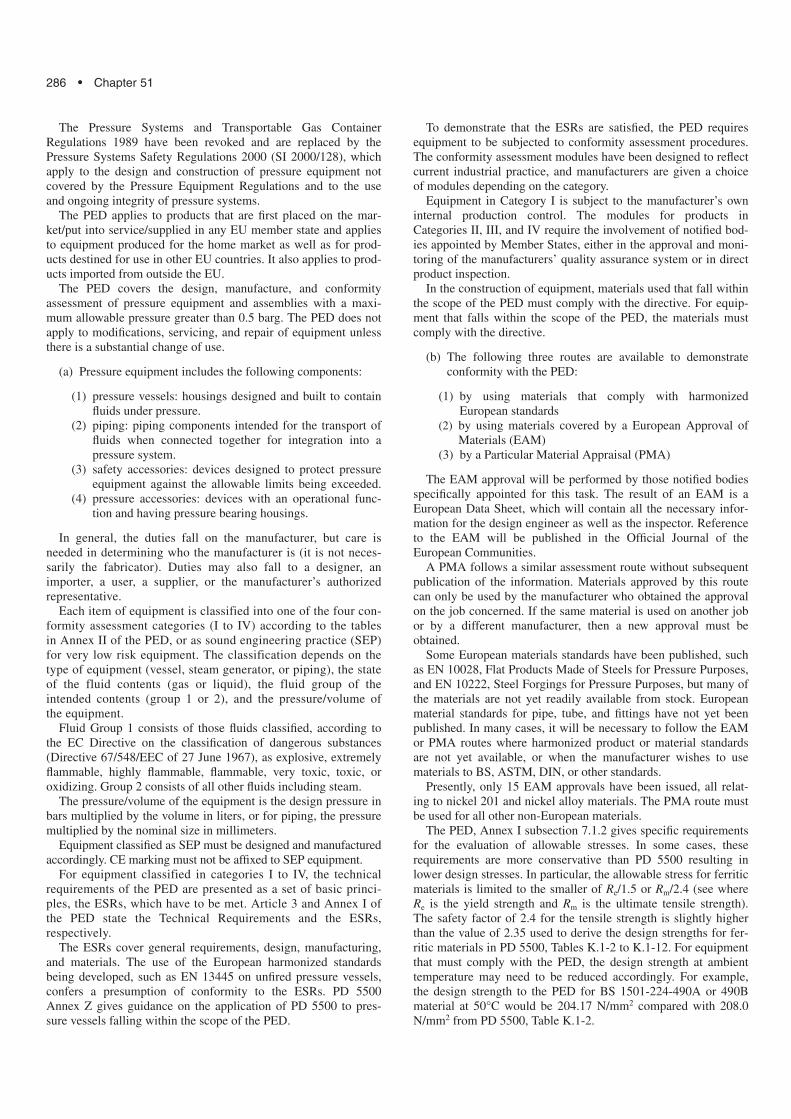
This strain is a function of the mode shape of collapse of thevessel and it, in turn, is a function of the unsupported length,diameter, and thickness of the shell. The theoretical bucklingstrain is given in graphical form and also by a supporting equation(see Fig. 51.3).
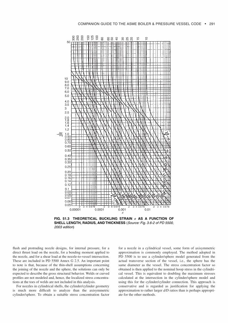
To correct for real vessels that may have slight shape imperfec-tions and some residual compressive stress, a graph was providedby Kendrick [15] that relates the theoretical collapse pressure tothe actual experimental collapse pressure with a 1.5 safety factor.This graph is nondimensionalized (see Fig. 51.4) by dividing bythe yield pressure found previously (i.e., K � Pm/Py and � �Pallow/Py).
Spherical shells and dished ends are designed in a similar man-ner using appropriate equations for a spherical shell. Again, two
pm �Ee�
R
pressure quantities are evaluated. The theoretical buckling pres-sure is related to the actual collapse load using the lower of thetwo curves shown in Fig. 51.4.
The calculations are valid for cylindrical shells that are circularto within 0.5% on the radius. This tolerance may be increasedat the design stage if the design external pressure is increased inthe ratio of (increased percentage of radial tolerance/0.5). Forexample, if the radial tolerance is increased to 0.8%, then thedesign external pressure must be increased by a factor of 1.6. Amore refined method for evaluating the allowable external pres-sure when the radial tolerance exceeds 0.5% is given in Annex M,but this procedure requires measurements of the as-built shape,which are not available until after the vessel has been fabricated.
This procedure satisfies the interstiffener buckling condition.When stiffeners are present, interstiffener buckling must berechecked; however, the stiffener shell and ring must satisfy theoverall buckling requirements. In addition, the proportions ofthe stiffener must not exceed prescribed limits. This ensures thatthe tripping condition will not prevail.
51.2.5 Nozzle ReinforcingThe traditional way of reinforcing an opening or nozzle is to
provide material near the hole in excess of the minimum thicknessrequired for the individual components considered as unpiercedshells. Planes through the center of the opening and normal to thevessel surface are considered, and the area (in the plane) of addi-tional material is required to be at least equal to the area removedby making the hole in a shell of minimum thickness. This type ofdesign approach has been applied very widely. It was used, forinstance, in BS 1500 and BS 1515 pressure vessel codes and inBS 1113, the water-tube boiler code, and is found in Europeancodes as well as various sections of the ASME Boiler andPressure Vessel Code.
A different form of presentation, generally known as the pres-sure-area method, is used in the French pressure vessel code(CODAP) [15]. Here, in essence, the product of the total area ofmaterial within the defined region and the design stress, f, is com-pared with the product of the design pressure, p, and the area overwhich the pressure acts. The pressure-area method has beenadopted for the European unfired pressure vessel standard EN13445 and the simple unfired pressure vessel standard EN 286,and it is now included as an alternative method in PD 5500Section 3.5.4.9.
One of the main disadvantages of the area-replacementapproach is that it gives no information on the stresses and thesecan vary considerably from one design to another, resulting in dif-fering performance especially under fatigue conditions. Also, themethod is not readily capable of being extended to situationswhere there are significant loads in addition to pressure.
In the UK, the main approach for the design of nozzles andtheir reinforcement has been based on stress analysis and this,thereafter, being cast into a design-by-rule method.
For nozzles in spherical shells, the methods are based on thework of Leckie and Penny with their solution of the elastic, small-displacement, thin-shell equations for an intersecting cylinder andsphere. In this, the maximum stress is due to some loading at thenozzle intersection, when expressed as a stress concentration fac-tor K by dividing by the nominal stress produced in the vessel.They did this by observing that, for useful ranges of r/R and R/T,these variables can be combined, and the SCF expressed as a func-tion of the parameter independently of the precise values of r/Rand R/T, so long as is fairly small. Curves were given for both
FIG. 51.2 BUCKLING FORMS FOR STIFFENER CYLINDRI-CAL SHELLS (Source: Fig. 3.6-2 of PD 5500, 2003 edition)
COMPANION GUIDE TO THE ASME BOILER & PRESSURE VESSEL CODE • 291
flush and protruding nozzle designs, for internal pressure, for adirect thrust load on the nozzle, for a bending moment applied tothe nozzle, and for a shear load at the nozzle-to-vessel intersection.These are included in PD 5500 Annex G 2.5. An important pointto note is that, because of the thin-shell assumptions concerningthe joining of the nozzle and the sphere, the solutions can only beexpected to describe the gross structural behavior. Welds or curvedprofiles are not modeled and, hence, the localized stress concentra-tions at the toes of welds are not included in this analysis.
For nozzles in cylindrical shells, the cylinder/cylinder geometryis much more difficult to analyze than the axisymmetriccylinder/sphere. To obtain a suitable stress concentration factor
for a nozzle in a cylindrical vessel, some form of axisymmetricapproximation is commonly employed. The method adopted inPD 5500 is to use a cylinder/sphere model generated from theactual transverse section of the vessel, i.e., the sphere has thesame diameter as the vessel. The stress concentration factor soobtained is then applied to the nominal hoop stress in the cylindri-cal vessel. This is equivalent to doubling the maximum stressescalculated at the intersection in the cylinder/sphere model andusing this for the cylinder/cylinder connection. This approach isconservative and is regarded as justification for applying theapproximation to rather larger d/D ratios than is perhaps appropri-ate for the other methods.
FIG. 51.3 THEORETICAL BUCKLING STRAIN � AS A FUNCTION OFSHELL LENGTH, RADIUS, AND THICKNESS (Source: Fig. 3.6-2 of PD 5500,2003 edition)
292 • Chapter 51
The design approach for nozzle reinforcement is based on elas-tic stresses used in conjunction with shakedown criteria. This isthe same approach as used in older UK codes, namely, BS 3915(steel vessels for primary circuits of nuclear reactors) in 1965 andin the 1968 edition of BS 1515. In BS 3915 and BS 1515, the per-mitted elastically calculated stress range was limited to 2.25fwhere f is the design stress; the same method is used in PD 5500for nozzles in spherical vessels. For nozzles in cylindrical vessels,a slightly different approach has been employed. Shakedown fac-tors are taken from a paper by Macfarlane and Findlay [16].Assuming a Tresca yield criterion and uniaxial condition at thecrotch corner, it can easily be shown that
where
K � is the elastic SCF obtained from a Leckie and Penny for-mulation
When the loading consists of cycling between zero and designpressure, limiting the stress range in effect means controlling themaximum elastic stress. The latter is the product of the SCF andthe membrane stress near the nozzle. If it is necessary to reducethe maximum stress, additional material can be placed near theintersection aimed primarily at reducing the SCF. Alternatively,the vessel can be thickened by means of a reinforcing pad, or ageneral increase in plate thickness, giving a reduced local mem-brane stress. A combination of these methods can also be used.
The theoretical background to Section 3.5.4.3 of PD 5500involves many simplifications and is limited in scope. For exam-ple, only isolated, circular nozzles radial to the vessel are consid-ered. The design curves apply only to nozzles sufficiently distant
Ks �4K � 3
2K � 1
from each other, and any further significant structural discontinu-ities that the maximum stresses at the junction are not affected.For the particular case of a nozzle or opening in a dished end, theminimum acceptable distance from the vessel/end junction asone-tenth of the vessel diameter is needed for the provisions ofSection 3.5.4.3 to be applicable.
For multiple nozzles in some vessel applications, it is necessaryto have a large number of small nozzles (or tube connections) andclose pitching often results. It is usually possible to arrange thetubes in rows in either a rectangular or triangular pattern.Reinforcement is provided by an increase in the general vesselthickness determined using a ligament efficiency factor. Thisapproach was extensively developed for use in BS 1113, thewater-tube boiler code.
In addition to this design approach, PD 5500 gives guidance onthe thickness of the nozzle for external force and moments load-ings and also provides data for the calculation of shakedown loadsfor nozzles in spherical vessels.
In 1996, Appendix F in PD 5500 was completely revised. Theprevious calculation method was replaced with a pressure-areamethod based on that used in the European unfired pressure ves-sel standard EN 13445. This method is now incorporated into PD5500 Section 3.5.4.9. The method is well established and is usedwith some variations in many European pressure vessel codes,including CODAP and AD Merkblatter [17].
51.2.6 Bolted Flanged JointsMost inspection openings or nozzles on vessels are provided
with circular-type standard flanges for quick, easy disassembly ofclosing covers or connected piping. Under normal circumstances,when using standard, rated flanges (such as BS 1560, BS 4504,BS EN 1092, BS EN 1759, or ASME B16.5), calculations neednot be performed because the design of the flange will have beenpreviously covered and noted on the supplied test certificate. Only
FIG. 51.4 GRAPH OF NONDIMENSIONALISED ALLOWABLE EXTERNAL PRESSUREVERSUS THEORETICAL COLLAPSE LOAD (Source: Fig. 3.6-3 of PD 5500, 2003 edition)
COMPANION GUIDE TO THE ASME BOILER & PRESSURE VESSEL CODE • 293
nonstandard flanges are designed or existing flanges checked formaximum working pressures.
There are three main types of circular, bolted flange covered inPD 5500 Section 3.8 as follows:
(a) Narrow-Faced Flanges. These are flanges where all thegasket contact area lies inside the circle enclosed by thebolts, and they are designed in accordance with subsection3.8.3. PD 5500 also covers ungasketed seal-welded flangesin subsection 3.8.5.
(b) Full-Faced Flanges. These are flanges where the gasketcontact area extends outside the bolt circle. Full-facedflanges with soft, ring-type gaskets are designed in accor-dance with subsection 3.8.4. A simple method for full-faced flanges with metal-to-metal contact outside the boltcircle is now included in PD 5500 subsection 3.8.8.
(c) Reverse Flanges. Theses are flanges where the shell isattached at the outer edge of the flange. They are usedwhere there is a requirement to limit the maximum outsidediameter of the vessel. Narrow-faced reverse flanges aredesigned in accordance with subsection 3.8.6, and full-facedreverse flanges are in accordance with subsection 3.8.7.
PD 5500 Enquiry Case 5500/133 covers rectangular, narrow-faced and full-faced flanges.
When standard flanges cannot be used or are not appropriate tothe circumstances, then it becomes necessary to design the joint indetail to match specific requirements. PD 5500 provides methodsfor analysis and design of a range of special joints, allowing thedesigner to create a design for the most appropriate joint in agiven solution.
Flanged joint behavior has been the subject of detailed researchfor many decades. In all this time, probably the most significantcontribution was the paper published in 1937 by Waters,Wesstrom, Rossheim, and Williams [18], in which the authors, forthe first time, the comprehensive flange design system thatbecame the basis of the well-known Taylor Forge method. Themethod of analysis used involves modeling the joint elementsusing simplified plate-and-shell theory with known boundary con-ditions, and then combining the elements to derive stresses in thevarious parts. This analysis was the first complete analysis thatconsidered the flange, hub, and shell as properly defined entitieswith minimal approximation.
Wide acceptance and the relative simplicity in its applicationhave made the Taylor Forge method the most widely used flangedesign technique in modern use, and it forms the basis of theflange design sections of PD 5500, ASME BPVC Section VIII,and many other codes around the world. However, this methodinvolves several assumptions that potentially limit its applicabilityto certain classes of joints. The technique has suffered from a fewproblems, most notably the potential for joint leakage due to theincreased flange flexibility of the inherently lighter (and moreeconomic) joints. Although this problem was later cured by theintroduction of an equation-limiting flange rotation, the TaylorForge method remains the prescribed method in the UK code.
The method requires that the geometry of the joint be specifiedalong with details of the preferred sealing element or gasket. Thegasket requires a certain amount of bolt preload to initialize andprovide a seal. This is defined by the parameter y and this factorhelps determine the required load for bolt-up. A second parame-ter, m, is related to the ability to seal once compressed and is usedto determine the amount of bolting required to maintain a seal inthe operating condition. From these conditions, the actual bolting
requirements can be established and the number and core area ofbolts can be fixed. Thereafter, the various moments are calculatedand the stresses in the flange ring and shell hub are evaluated. Thestresses are categorized and limited according to their nature.Membrane stresses are limited to two-thirds of yield and bendingstress to yield. However, the method assumes that the design pres-sure is used to size the flange ring and, if designed to the limit,then some limited yielding can occur during hydrotest. If leakagedoes occur during test, then the test should stop, the gasketreplaced, and the test repeated. Some problems have been experi-enced in certain cases with bolted flanged joints in vessels with adiameter over 1 m. A stress reduction factor, k, has recently beenintroduced to limit the stress levels in the shell hub connection.
If 1000 � D � 2000, then ; if D � 2000,
then .
Flange calculations are quite complex and will usually involveseveral iterations before the design is finalized. Because of this,most flange design is now performed using computer programs.
51.2.7 Flat Plates and CoversFlat ends or domed covers may be used to blank off flanges for
pressure tests (blind flange), provide manway closures, or fix orremove end closures. This section covers the design rules given inPD 5500 subsection 3.5.5 for welded or bolted flat ends and sub-section 3.5.6 for domed and bolted ends. There are rules govern-ing the design of three groups of flat ends and plates:
(a) welded flat ends and covers(b) non welded flat ends and covers(c) flat-stayed plates without openings (not covered in this
course)
Any of these ends or covers may be noncircular and the appro-priate factors are included in the design methods. Welded flatends are normally used only for small-diameter vessels operatingat low pressures. This is because of the large bending stressesinduced in a flat plate subject to pressure loading. This results inflat ends being considerably thicker than the corresponding dishedends.
The calculations for the minimum thickness of a circularunstayed flat end are given in subsection 3.5.5.3.1, and for a non-circular flat end they are given in Enquiry Case 5500/133.
The basic thickness of a flat end can be evaluated by consider-ing the analysis of a circular plate subject to pressure loading[19]. The most important consideration is the restraint imposed bythe connection to the shell. This is established by the use of a fac-tor, C, which ranges from 0.3 for a clamped edge to 0.41 for asimply supported edge.
Also, the stresses in the shell at the edge of the plate can beevaluated and these are limited to 2.7f. This should be comparedwith the 3f allowed in PD 5500 Annex A, clause A.3.4.2.4. Thelower value provides some ability to accept additional loads.
For flat-bolted covers, the methods are similar to those for flatplates with the addition of a term to account for the stressesinduced by the bolting.
The method in Section 3.5.6 of PD 5500 allows the design of adished closure or head connected to a flanged ring with a suitable
e � CD√ p
f
k �4
3
k �2
3 �1 �D
2000 �
294 • Chapter 51
narrow-faced gasket to be evaluated. The procedure is similar tothe ASME code method and to other international codes. Theanalysis is somewhat simplified and empirical factors are intro-duced to take account of the discontinuity forces that interactbetween the two components.
51.2.8 Jacketed VesselsThe rules for the design of jacketed vessels are given in Section
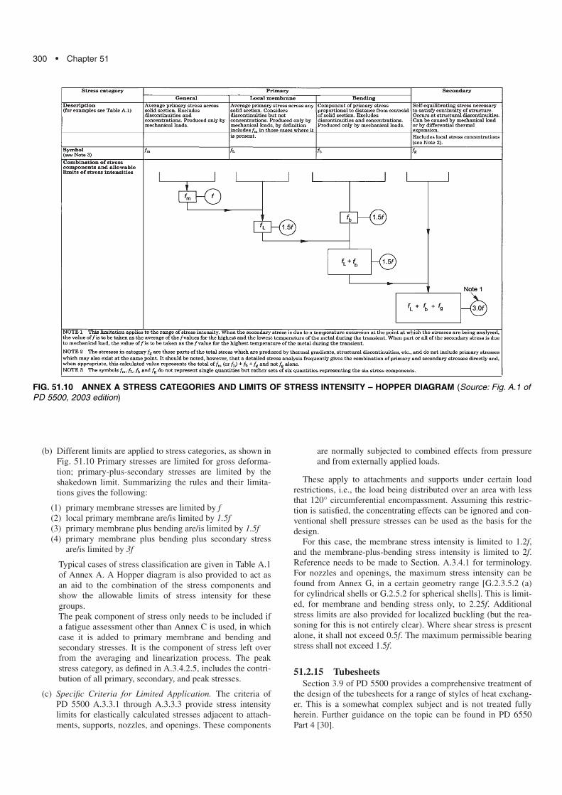
3.11 of PD 5500 as part of the main design section. The reasonfor the adoption of a jacket is to provide either heating or coolingto the main vessel contents. Also, the jacket may provide a sealedinsulation chamber for the vessel. The use of such jacketed ves-sels is primarily found in the process industry, and these types ofvessels are usually cylindrical in construction. Jackets are tradi-tionally fabricated in the form of an additional shell belt, encom-passing part or all of the main vessel shell; jackets can also oftenencompass the lower dished head (see Fig. 51.5).
Because there are numerous types of jacket designs, the rulesprovided in PD 5500 allow the main elements of the jacketed ves-sel to be analyzed and designed in accordance with the require-ments for each individual element. However, due to the possibilityof differing pressures in the jacket interspace, there are specificguidelines provided that ensure that any additional pressure load-ing transferred to the main shell is adequately handled. InSeptember 2001, Enquiry Case 5500/128 was issued, giving pre-liminary rules for a less-conservative design of jacket blockingrings.
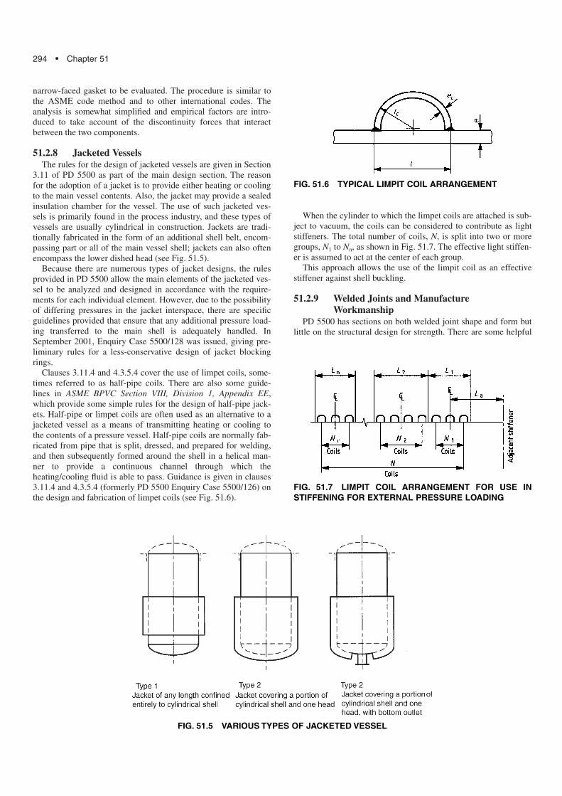
Clauses 3.11.4 and 4.3.5.4 cover the use of limpet coils, some-times referred to as half-pipe coils. There are also some guide-lines in ASME BPVC Section VIII, Division 1, Appendix EE,which provide some simple rules for the design of half-pipe jack-ets. Half-pipe or limpet coils are often used as an alternative to ajacketed vessel as a means of transmitting heating or cooling tothe contents of a pressure vessel. Half-pipe coils are normally fab-ricated from pipe that is split, dressed, and prepared for welding,and then subsequently formed around the shell in a helical man-ner to provide a continuous channel through which theheating/cooling fluid is able to pass. Guidance is given in clauses3.11.4 and 4.3.5.4 (formerly PD 5500 Enquiry Case 5500/126) onthe design and fabrication of limpet coils (see Fig. 51.6).
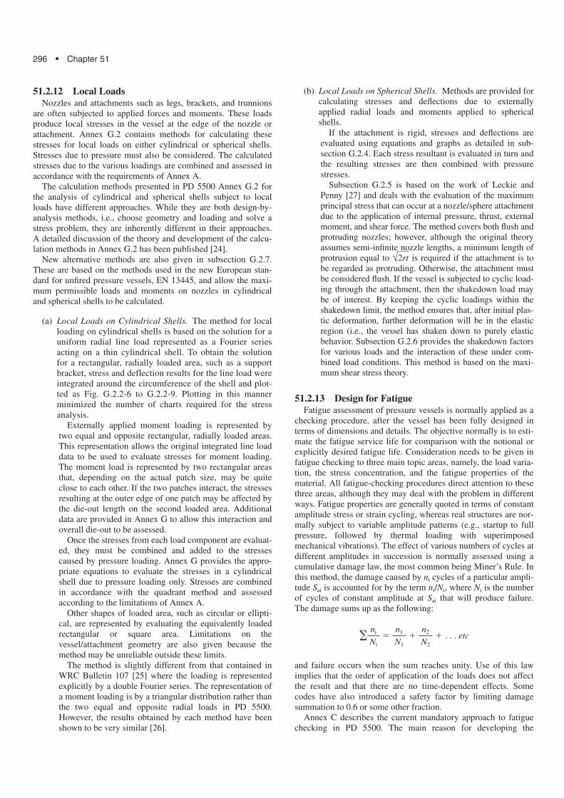
When the cylinder to which the limpet coils are attached is sub-ject to vacuum, the coils can be considered to contribute as lightstiffeners. The total number of coils, N, is split into two or moregroups, N1 to Nn, as shown in Fig. 51.7. The effective light stiffen-er is assumed to act at the center of each group.
This approach allows the use of the limpit coil as an effectivestiffener against shell buckling.
51.2.9 Welded Joints and ManufactureWorkmanship
PD 5500 has sections on both welded joint shape and form butlittle on the structural design for strength. There are some helpful
FIG. 51.5 VARIOUS TYPES OF JACKETED VESSEL
FIG. 51.7 LIMPIT COIL ARRANGEMENT FOR USE INSTIFFENING FOR EXTERNAL PRESSURE LOADING
FIG. 51.6 TYPICAL LIMPIT COIL ARRANGEMENT

COMPANION GUIDE TO THE ASME BOILER & PRESSURE VESSEL CODE • 295
comments on manufacture and workmanship including usefulinformation on preheating for welding, stress relieving, and shapemeasurements. This is not discussed in detail here.
51.2.10 Inspection and TestingThe standard test pressure for a vessel section to PD 5500 shall
be not less that pt, as follows:
where
fa and ft � the design strengths at ambient and temperature,respectively
t � is the shell thicknessc � is the corrosion allowance
This allows the vessel to be tested at room temperature but fac-tor in the changes in stress at high temperature and also when thevessel is corroded.
This equation applies to all levels of construction. Where thevessel to be tested consists of several nonconnected parts (as in aheat exchanger), then each part is tested independently with theappropriate standard test pressure. There are particular cases thatrequire special consideration. These include glass-lined vessels orthose where coating could be damaged, vessels under externalpressure, and jacketed vessels. A full description of the limits ofthe standard test pressure and the applicable test pressures for allother cases are given in Section 5.8.5.
Where a component is subjected to an internal test pressure thatis greater than 1.08 times the standard test pressure, then a designcheck must be carried out to ensure that the general membranestress in that component during the test does not exceed 90% ofthe minimum specified yield or proof stress of the material.
For vertical vessels, the effect of the pressure due to the statichead of the test liquid must be considered. Tall vessels are nor-mally tested horizontally in the shop, but may be required to betested vertically on site. For large vessels, the weight of the testliquid will be considerable (a cubic meter of water weighs 1 ton)and may control the design of the supports.
51.2.11 SupportsPD 5500 Section 3.7 and Annex G, Section G.3 are concerned
with the supports for pressure vessels (and other fittings) that arecarried by the shell or ends of a pressure vessel. The main designconsideration is to understand the effect of these supports on theshell. No account is made of the support design. These can nor-mally be designed by the usual structural methods. PD 5500 givessome general information about supports and attachments, butdoes not contain any calculation procedures. Supports producelocal moments and membrane forces in the vessel wall and theseare treated by applying the rules for local loads on pressure vesselshells in PD 5500 Annex G, Section G.2, with the exception ofsaddle supports. The assessment of stresses in saddle-mountedvessels is covered by Annex G, subsection G.3.3. A derivation ofthe equations and constants used in subsection G.3.3 is given inPD 6497 [20].
When vessels are supported in the horizontal plane, they aresubject to longitudinal bending moments and local shear forcesdue to the weight of the vessel and its contents. In addition tothese, local stresses arise at the support or fitting. A vessel may
pt � 1.25 �pfa
ft�
t
t � c �
be designed to be located in the vertical position in service, butmost vessels, both horizontal and vertical, are constructed andtransported in the horizontal position. Some vertical vesselsmay also have their hydraulic pressure test in the horizontalposition.
In all cases, it is preferable to support the vessel at two profilesequidistant from each end. If the vessel is very flexible or is sub-ject to external pressure, then ring supports may be required.However, under normal circumstances, saddle supports are themost commonly used method of supporting such vessels duringfabrication, transportation, and in service. It is noted that leg sup-ports are used for small L/r ratios where the longitudinal stressesare small in comparison to the axial stresses in the shell due topressure.
This arrangement means that the vessel acts like a beam inbending and this area requires to be considered at the designstage. Unlike the ring support, the shell is only supported overpart of its circumference, typically 120° wraparound, and highstresses can occur at several areas in the plane of the saddle.Therefore, the twin-saddle support problem is one of the morecomplex problems covered in PD 5500 and is not discussed indetail herein.
The procedure, based on the work of Zick [21] and implement-ed into PD 5500 by Tooth [22], can be broken down into fourmain design elements. When the vessel is situated on twin sad-dles, the following high-stress (f) areas must be investigated:
(a) longitudinal bending stresses at the vessel midspan, i.e., f1
at the highest and f2 at the lowest sections(b) longitudinal stresses at the saddles, i.e., f3 at the highest or
equator and f4 at the lowest sections(c) tangential shearing stresses at the saddles, i.e., q (and qe
when saddle is near the end)(d) circumferential stresses at the saddles, i.e., f5 at the lowest
and f6 at the horn sections
Each of these stresses must be assessed against specific criteriadepending on the influence of other loads and the possible failuremode (e.g., plastic deformation or buckling collapse).
Consideration must be given to establishing the bendingmoments at the midspan and at the plane of the support.Thereafter, a series of factors are derived that relate the locationof the support with respect to the end. If the support is near thevessel end, then the shell remains circular and the full section isavailable to resist bending. If not, then only a partial section isavailable. The highest stress is often at the saddle horn, where theshell bends over the support and has little or no resistance to radi-al deformation. Again, various factors are evaluated and thestress, f6, determined. However, the absolute value of f6 should notexceed 1.25f. This is significantly different from the 3f secondarystress limit that should be used. This reduction is present due tothe assumptions in the method and also the work by Tooth thathas shown the method to underpredict stress levels when the sup-port is rigid, i.e., like a concrete or very substantial support. Forflexible saddles, the method provides reasonable agreement withexperiments.
If the value of the stress f6 calculated using the above method isless than 1.25f, then this will provide adequate safety margin forstatic loading conditions; however, this value of f6 is not appropri-ate for use in a fatigue assessment [23]. A procedure is given insubsection G.3.3.2.8 for the determination of a maximum stressthat, when added to the stress due to pressure, can be used in afatigue analysis to Annex C.
296 • Chapter 51
(b) Local Loads on Spherical Shells. Methods are provided forcalculating stresses and deflections due to externallyapplied radial loads and moments applied to sphericalshells.
If the attachment is rigid, stresses and deflections areevaluated using equations and graphs as detailed in sub-section G.2.4. Each stress resultant is evaluated in turn andthe resulting stresses are then combined with pressurestresses.
Subsection G.2.5 is based on the work of Leckie andPenny [27] and deals with the evaluation of the maximumprincipal stress that can occur at a nozzle/sphere attachmentdue to the application of internal pressure, thrust, externalmoment, and shear force. The method covers both flush andprotruding nozzles; however, although the original theoryassumes semi-infinite nozzle lengths, a minimum length ofprotrusion equal to is required if the attachment is tobe regarded as protruding. Otherwise, the attachment mustbe considered flush. If the vessel is subjected to cyclic load-ing through the attachment, then the shakedown load maybe of interest. By keeping the cyclic loadings within theshakedown limit, the method ensures that, after initial plas-tic deformation, further deformation will be in the elasticregion (i.e., the vessel has shaken down to purely elasticbehavior. Subsection G.2.6 provides the shakedown factorsfor various loads and the interaction of these under com-bined load conditions. This method is based on the maxi-mum shear stress theory.
51.2.13 Design for FatigueFatigue assessment of pressure vessels is normally applied as a
checking procedure, after the vessel has been fully designed interms of dimensions and details. The objective normally is to esti-mate the fatigue service life for comparison with the notional orexplicitly desired fatigue life. Consideration needs to be given infatigue checking to three main topic areas, namely, the load varia-tion, the stress concentration, and the fatigue properties of thematerial. All fatigue-checking procedures direct attention to thesethree areas, although they may deal with the problem in differentways. Fatigue properties are generally quoted in terms of constantamplitude stress or strain cycling, whereas real structures are nor-mally subject to variable amplitude patterns (e.g., startup to fullpressure, followed by thermal loading with superimposedmechanical vibrations). The effect of various numbers of cycles atdifferent amplitudes in succession is normally assessed using acumulative damage law, the most common being Miner’s Rule. Inthis method, the damage caused by ni cycles of a particular ampli-tude Sai is accounted for by the term ni/Ni, where Ni is the numberof cycles of constant amplitude at Sai that will produce failure.The damage sums up as the following:
and failure occurs when the sum reaches unity. Use of this lawimplies that the order of application of the loads does not affectthe result and that there are no time-dependent effects. Somecodes have also introduced a safety factor by limiting damagesummation to 0.6 or some other fraction.
Annex C describes the current mandatory approach to fatiguechecking in PD 5500. The main reason for developing the
� ni
Ni�
n1
N1�
n2
N2� . . . etc
√2rt
51.2.12 Local LoadsNozzles and attachments such as legs, brackets, and trunnions
are often subjected to applied forces and moments. These loadsproduce local stresses in the vessel at the edge of the nozzle orattachment. Annex G.2 contains methods for calculating thesestresses for local loads on either cylindrical or spherical shells.Stresses due to pressure must also be considered. The calculatedstresses due to the various loadings are combined and assessed inaccordance with the requirements of Annex A.
The calculation methods presented in PD 5500 Annex G.2 forthe analysis of cylindrical and spherical shells subject to localloads have different approaches. While they are both design-by-analysis methods, i.e., choose geometry and loading and solve astress problem, they are inherently different in their approaches.A detailed discussion of the theory and development of the calcu-lation methods in Annex G.2 has been published [24].
New alternative methods are also given in subsection G.2.7.These are based on the methods used in the new European stan-dard for unfired pressure vessels, EN 13445, and allow the maxi-mum permissible loads and moments on nozzles in cylindricaland spherical shells to be calculated.
(a) Local Loads on Cylindrical Shells. The method for localloading on cylindrical shells is based on the solution for auniform radial line load represented as a Fourier seriesacting on a thin cylindrical shell. To obtain the solutionfor a rectangular, radially loaded area, such as a supportbracket, stress and deflection results for the line load wereintegrated around the circumference of the shell and plot-ted as Fig. G.2.2-6 to G.2.2-9. Plotting in this mannerminimized the number of charts required for the stressanalysis.
Externally applied moment loading is represented bytwo equal and opposite rectangular, radially loaded areas.This representation allows the original integrated line loaddata to be used to evaluate stresses for moment loading.The moment load is represented by two rectangular areasthat, depending on the actual patch size, may be quiteclose to each other. If the two patches interact, the stressesresulting at the outer edge of one patch may be affected bythe die-out length on the second loaded area. Additionaldata are provided in Annex G to allow this interaction andoverall die-out to be assessed.
Once the stresses from each load component are evaluat-ed, they must be combined and added to the stressescaused by pressure loading. Annex G provides the appro-priate equations to evaluate the stresses in a cylindricalshell due to pressure loading only. Stresses are combinedin accordance with the quadrant method and assessedaccording to the limitations of Annex A.
Other shapes of loaded area, such as circular or ellipti-cal, are represented by evaluating the equivalently loadedrectangular or square area. Limitations on thevessel/attachment geometry are also given because themethod may be unreliable outside these limits.
The method is slightly different from that contained inWRC Bulletin 107 [25] where the loading is representedexplicitly by a double Fourier series. The representation ofa moment loading is by a triangular distribution rather thanthe two equal and opposite radial loads in PD 5500.However, the results obtained by each method have beenshown to be very similar [26].

COMPANION GUIDE TO THE ASME BOILER & PRESSURE VESSEL CODE • 297
approach in the revised Annex C was that the philosophy onwhich the previous method, developed from the ASME Codemethod, was based was inappropriate for weld areas in vesselswhere fatigue failures are most likely (see Fig. 51.8). The assess-ment of load variation is virtually the same in both approaches,the main differences being in the philosophies used to assess andlink the stress concentration effects and the fatigue strength/life-property curves (S/N curves).
In the ASME approach, only one S/N curve was given to coverall metallic materials used in the vessel, aside from bolts. Thiscurve was based on data obtained by testing flush-ground weldsunder strain control (hence, without significant stress concentra-tion effect), and the design curve was set four standard deviationsbelow the mean of the test results to give a safety margin (equiva-lent to a factor of 2.2 on stress and 15 on life). The curve wasexpressed in terms of stress amplitude Sa (being half the stressrange) and in the units used in the Standard; the linear part can berepresented by the following equation:
which is typical of the log-log form for fatigue curves.The peak stress amplitude in the region of the vessel to be
assessed was then calculated in terms of the nominal stress ampli-tude times a universal stress concentration factor of 2.5 for any
S3.5a N � 1.1 � 1012
detail other than a smoothly dressed weld or a threaded member.Table 51.1 gives the different bases of the ASME-based and thecurrent Annex C.
The complexity of stress concentration factors in welds and thedifficulty of estimating these properly are recognized in theAnnex C approach by including the stress concentration effect ofthe weld geometry in the family of S/N curves provided for differ-ent geometries (see Fig. 51.9). The curves do not, however,include the effect of discontinuity stress concentrations such aswould occur at a shell/head. junction.
The Annex C associates each curve with pictures of typicalwelded details (Table C.2), which have been found throughfatigue testing programs to have the indicated strengths. Thedesigner is not given an SCF, therefore, but assesses the stressconcentration effect by selecting the detail that corresponds bestto the one he is checking. The fatigue curves are cast in terms ofthe nominal stress range Sr (note Sr � 2 � Sa). The S/N curves arealso given in equation form, using the constants m and A given inTable 51.2.
(a) ASME Stresses and Stress Concentration Factors. TheASME Code is based on a single SN curve originating fromuni-axial tests on flush-ground, butt-weld specimens. The
Smr N � A
FIG. 51.8 ASME-BASED/OLD BS 5500 FATIGUE DESIGN CURVE (Source: Fig. C.2.1 of BS 5500,1994 edition)
TABLE 51.1 COMPARISON OF THE BASES OF ASME AND PD 5500 FATIGUE METHODS (Source: Table C.1 AnnexC of PD 5500, 2003 edition)
Basis ASME/old BS 5500 Annex C
Fatigue Data ‘Single’ S-N curve for all materials Several S-N curves for different weldsRelevant Stress Max stress intensity range � 2 Max normal stress perpendicular to
crack directionStress Level Gross and local effects to be included Gross effects to be includedWeld Detail Consideration SCF � 2.5 MIN (Butt or fillet) Included in all S-N curves

298 • Chapter 51
relevant stress in this procedure was the alternating stressintensity, denoted as Salt and defined as , whereSr is the absolute magnitude of the stress intensity. It isnoted that the stress intensity is the maximum absolutevalue of the stress differences of the three principal stress-es; the values of the principal stresses may change through-out a load cycle and, therefore, the designer should ensurethat the maximum stress differences are considered withrespect to time over the whole cycle. The above procedurerelates primarily to the case where the principal stressdirection remains constant over the load cycle. In thosecases where the principal stress directions change, therange of fluctuation should be determined from the stressdifferences to find the full algebraic range. It may be neces-sary to try various points in time to find the one that resultsin the largest value of the alternating stress intensity.
There are various features of a vessel and the weld thatwill reduce the fatigue life of the component. These are
Salt � 0.5Sr
dealt with by multiplying the nominal stress by an appro-priate stress concentration factor (SCF) or fatigue reductionfactor in calculating the peak stress. Stress concentrationfactors are not given explicitly but reference is made to var-ious well-known publications in the bibliography.An SCF of 1 was assumed for a dressed, smooth buttweld. A stress concentration factor of at least 2.5 wasused for the toe of an as-welded butt or fillet weld. For acontour-dressed fillet weld, the stress concentration wouldbe dependent on the local geometry and suitable SCF val-ues would have to be obtained from technical literature[28].
(b) PD 5500 Stresses. In Annex C, the fatigue assessment isbased on the primary-plus-secondary stress category.Direct stress is used rather than the stress intensity, whichis used elsewhere in PD 5500. The full stress range is used,regardless of applied or mean stress because the design S/N
FIG. 51.9 FAMILY OF FATIGUE DESIGN CURVES FROM ANNEX C OFPD 5500 (Source: Fig. C.3 of PD 5500, 2003 edition)
TABLE 51.2 DETAILS OF FATIGUE DESIGN CURVES
Class Constants of S-N curve Stress range atN � 107 cycles N/mm2
For N � 177 cycles for N � 107 cycles
m A1) m A1)
C2) 3.5 4.22 � 1013 5.5 2.55 � 1017 78D 3 1.52 � 1012 5 4.18 � 1015 53E 3 1.04 � 1012 5 2.29 � 1015 47F 3 6.33 � 1011 5 1.02 � 1015 40F2 3 4.31 � 1011 5 5.25 � 1014 35G 3 2.50 � 1011 5 2.05 � 1014 29W 3 1.58 � 1011 5 9.77 � 1013 251) for E � 2.09 � 105 N/mm2.2) if Sr � 766 N/mm2 or N � 3380 cycles, use class D curve.
COMPANION GUIDE TO THE ASME BOILER & PRESSURE VESSEL CODE • 299
curves provided take into account the effects of peak andresidual stresses.
However, the fatigue curves for bolting do not account forstress concentrations in the bolt, and the stress range shouldinclude a suitable concentration factor (see Annex C, clauseC.3.3.4).
When the directions of the principal stresses remain fixed, thenSr is the maximum range through which any of the principalstresses changes as follows:
f1 max � f1 min
f2 max � f2 min
f3 max � f3 min
where f1, f2, and f3 are the three principal stresses; usually f3 israrely relevant and can often be ignored.
If the principal stress directions change, then the three directand three shear components must be determined and, there-after, for each stress component, the algebraic differencebetween the stresses must be found. From this, the principalstresses can be found and Sr is the greatest of these principalstresses.
From stresses in weld metal, Sr is the maximum range of stressacross the effective weld throat, calculated as the load carried bythe weld divided by the throat area. This, therefore, assumes thatno load is carried by bearing between either of the two adjoiningcomponents.
For stress cycling in weld metal due to a single application andremoval of load,
where
� � the direct stress on the weld throat� � the shear stress on the weld throat
For complex cycling conditions, it is preferable to evaluate thevector difference of all pairs of extreme load conditions. It isalways safe to assume
where
�1 and �2 � the components of shear stress
Generally, in arriving at the primary-plus-secondary stressesrequired for use in Annex C, it is necessary to account forstructural discontinuities including the following: discontinu-ities such as cylinder-to-end junctions, changes in thickness,and welded-on rings; deviations from the intended shape,including ovality, peaking, and mismatched welds; and temper-ature gradients.
Methods in PD 5500 allow the required stresses to be evaluatedfor many geometries or at least allow a conservative estimate tobe made.
51.2.14 Design by AnalysisIn the early 1960s, the ASME BPVC Committee, having rec-
ognized with considerable foresight the advantages to be gainedfrom detailed stress analysis, introduced the so-called design-by-analysis route for nuclear pressure vessel design. The rules
Sr � √(�1max � �1min)2 � (�1max � �1min)2 � (�2max � �2min)2
Sr � √� 2 � � 2
formulated in the design by analysis approach were based onconcepts derived from plasticity theory in an attempt to avoidthe consequences of possible bursting or ratcheting failure andfatigue.
However, the effort in determining whether a vessel would failby any of these mechanisms was often considerable and expen-sive and only undertaken by experienced persons. Nevertheless, itwas realized that there were many more circumstances wherebenefit could be gained if detailed stress analysis were performed,essentially by proving a design by carrying out a proper stressanalysis.
This approach required an elastic analysis of the vessel or com-ponent (although it did not restrict design to elastic analysisalone) and the subsequent classification of the calculated shelltype stresses into certain categories, primary, secondary, and peak,to which different design allowables could be applied. Themethod of calculation was not specified, although it was clear atthe time that shell discontinuity analysis was seen as the mainmethod of analysis.
The dominant problem in design by analysis is not usually incarrying out the analysis but in the categorization of the resultingstresses. The rules governing this are not precise, but experienceand common practice coupled with the use of thin-shell calcula-tions has allowed some degree of reliability to be introduced intothe design process. If the elastic analysis is performed usingmore-detailed, modern continuum, finite-element calculations,then the categorization of the stresses and the extraction of shelltype through wall membrane and bending stresses becomesfraught with difficulty, even though some feel a finite elementsolution must be better.
The PD 5500 code committee essentially recognized the advan-tages of this design philosophy and subsequently incorporated it(with minor notational changes and with reference to the UKmaterial specifications) into PD 5500 as Annex A.
Essentially, design by analysis is based on the use of theresults of elastic stress analysis. When the ASME Code wasintroduced, the writers were specifically thinking of generalvessel stress analysis based on shell discontinuity analysis oron specific analysis for specific components. Current practicewould be to use advanced, finite-element analysis.Unfortunately, the pressure vessel codes do not really addressthe use of such methods, which can and does lead to variousproblems of interpretation.
(a) The main failure mechanisms that PD 5500 addresses arethe following:
(1) gross plasticity: large, obvious bulges in the shell(2) incremental collapse (or ratcheting): collapse by repeat-
ed load cycling, which increments the amount of plastic-ity through the thickness
(3) buckling: general collapse of the shell into a number ofmodes, normally attributed to compressive loads andapplied external pressure
(4) fatigue: repeated load cycling, either mechanical or ther-mal, which continually impairs the material and inducesa material breakdown
Once an analysis has been carried out, there follows theprocess of assigning the resulting stresses into specificcategories depending on the nature and source of thestress and its location and influence on adjacent compo-nents.
300 • Chapter 51
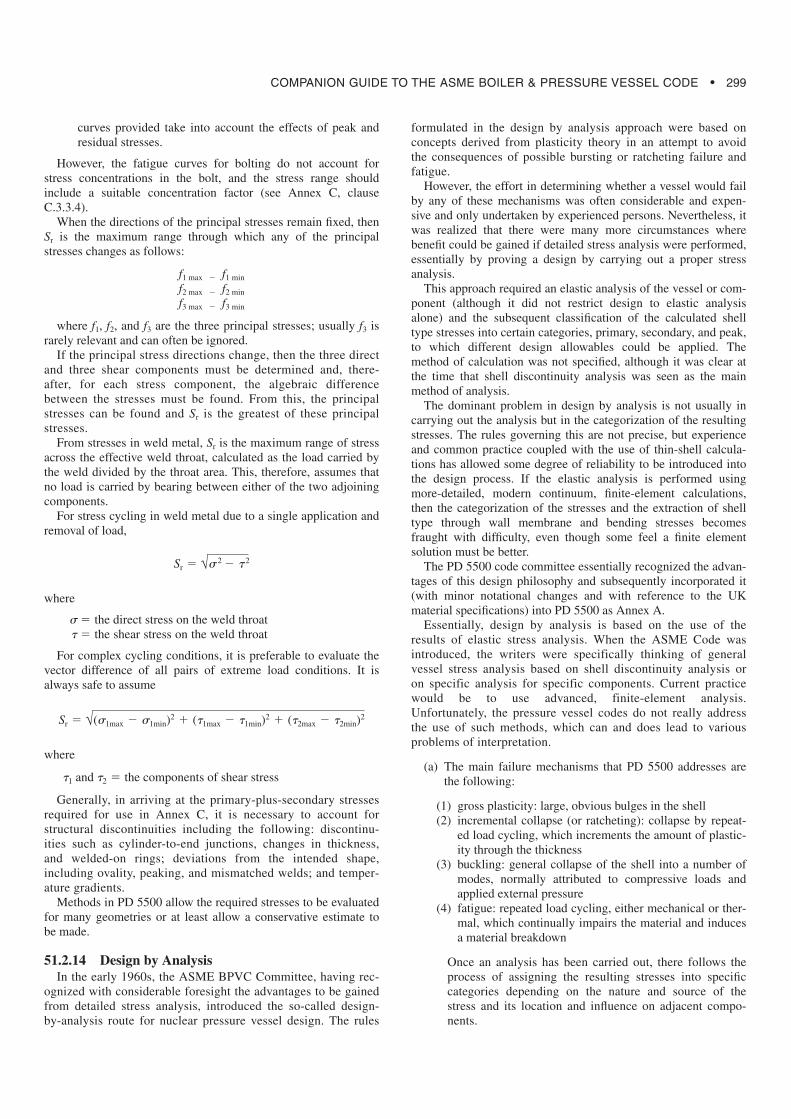
(b) Different limits are applied to stress categories, as shown inFig. 51.10 Primary stresses are limited for gross deforma-tion; primary-plus-secondary stresses are limited by theshakedown limit. Summarizing the rules and their limita-tions gives the following:
(1) primary membrane stresses are limited by f(2) local primary membrane are/is limited by 1.5f(3) primary membrane plus bending are/is limited by 1.5f(4) primary membrane plus bending plus secondary stress
are/is limited by 3f
Typical cases of stress classification are given in Table A.1of Annex A. A Hopper diagram is also provided to act asan aid to the combination of the stress components andshow the allowable limits of stress intensity for thesegroups.The peak component of stress only needs to be included ifa fatigue assessment other than Annex C is used, in whichcase it is added to primary membrane and bending andsecondary stresses. It is the component of stress left overfrom the averaging and linearization process. The peakstress category, as defined in A.3.4.2.5, includes the contri-bution of all primary, secondary, and peak stresses.
(c) Specific Criteria for Limited Application. The criteria ofPD 5500 A.3.3.1 through A.3.3.3 provide stress intensitylimits for elastically calculated stresses adjacent to attach-ments, supports, nozzles, and openings. These components
are normally subjected to combined effects from pressureand from externally applied loads.
These apply to attachments and supports under certain loadrestrictions, i.e., the load being distributed over an area with lessthat 120° circumferential encompassment. Assuming this restric-tion is satisfied, the concentrating effects can be ignored and con-ventional shell pressure stresses can be used as the basis for thedesign.
For this case, the membrane stress intensity is limited to 1.2f,and the membrane-plus-bending stress intensity is limited to 2f.Reference needs to be made to Section. A.3.4.1 for terminology.For nozzles and openings, the maximum stress intensity can befound from Annex G, in a certain geometry range [G.2.3.5.2 (a)for cylindrical shells or G.2.5.2 for spherical shells]. This is limit-ed, for membrane and bending stress only, to 2.25f. Additionalstress limits are also provided for localized buckling (but the rea-soning for this is not entirely clear). Where shear stress is presentalone, it shall not exceed 0.5f. The maximum permissible bearingstress shall not exceed 1.5f.
51.2.15 TubesheetsSection 3.9 of PD 5500 provides a comprehensive treatment of
the design of the tubesheets for a range of styles of heat exchang-er. This is a somewhat complex subject and is not treated fullyherein. Further guidance on the topic can be found in PD 6550Part 4 [30].
FIG. 51.10 ANNEX A STRESS CATEGORIES AND LIMITS OF STRESS INTENSITY – HOPPER DIAGRAM (Source: Fig. A.1 ofPD 5500, 2003 edition)
COMPANION GUIDE TO THE ASME BOILER & PRESSURE VESSEL CODE • 301
51.3 EN 13445
EN 13445 was developed as a harmonized standard for usewith the PED and is intended to cover the ESR of the PED. Useof the CEN standard is not mandatory in the PED, but vesselsdesigned, manufactured, and tested in accordance with the CENstandard will have an automatic presumption of conformity withthe ESR of the PED.
The major difference from other pressure vessel standards andcodes is that there is (or should be) no reference in the standard tothe responsibilities of the parties (the Purchaser, Manufacturer,and Independent Inspection Authority). This aspect is covered bythe PED.
There are some safety matters that the PED says must be con-sidered (e.g., venting and draining, external fire), not all of whichare mentioned in the standard.
The general layout of the standard and the philosophy behind itare similar to the UK approach in PD 5500:2000. There is natu-rally some common material because BS 5500 was always a well-regarded and well-maintained standard, but there are beneficialnew methods for dished ends, flanges, tubesheets, expansion bel-lows, and vessels of rectangular section. In recent years, there hasbeen a tendency for EN 13445 and PD 5500 to converge as newmethods or improvements to existing methods in the standardhave been incorporated into PD 5500.
Various safety factors are provided by the PED and are copiedverbatim; they were firstly agreed by the code writers at an earlystage and then transferred into the PED. Now that they are in thePED they can only be modified with great difficulty.
The standard consists of the following parts:
(a) Part 1, general(b) Part 2, materials(c) Part 3, design(d) Part 4, manufacture(e) Part 5, inspection and testing(f) Part 6, additional requirements for design and fabrication of
pressure vessels and vessel parts constructed of spheroidalgraphite cast iron
Each part contains various annexes, including an Annex Z thatlists the clauses of the standard addressing the ESRs and otherprovisions of the PED. (There is a similar Annex Z in PD 5500.)In common with other CEN standards, EN 13445 uses a commafor the decimal point.
51.3.1 Part 1, GeneralThis part gives the scope of the standard and contains some
general definitions, responsibilities of the manufacturer, andrequirements for symbols and units.
51.3.2 Part 2, MaterialsThis part gives general requirements for materials and lists
the various CEN standards for materials. It has several annexescontaining specific requirements, including those for the pre-vention of brittle fracture (similar to Annex D in PD 5500).There are no tables of design stresses; the evaluation of designstresses from the properties of the material is covered in Part 3.Carbon steels, low alloy steels, and austenitic stainless steelsare included, but nonferrous materials and creep are not yetcovered.
51.3.3 Part 3, DesignThe first six sections of Part 3 deal with general matters, such
as definitions, symbols and abbreviations, basic design criteria,and design stresses.
(a) Section 3, definitions, provides clarity in some areas that isan improvement over PD 5500. Distinctions are madebetween design pressure and calculation pressure andbetween design temperature and calculation temperature.These are particularly relevant for heat exchangers. A dis-tinction is also made among required thickness, analysisthickness, and nominal thickness (now adopted by PD5500).
(b) Section 5, basic design criteria, includes information oncorrosion, loadings, design methods, thickness, weld jointcoefficients, and design of welded joints.
(1) General. The requirements are applicable when the fol-lowing applies:
(a) The materials and welds are not subject to localizedcorrosion in the presence of products that the vessel isto contain.
(b) The design is outside the creep range.
This will be changed when the section on creep design is pre-pared.
(2) Corrosion. There is some clear guidance given for caseswhere reduction of wall thickness is possible as a resultof surface corrosion. The minimum corrosion allowanceof 1 mm in the 1999 draft has been removed.
(3) Load cases. Classification of load cases identifies threeclasses: normal operating load case, exceptional loadcases (e.g., internal explosion), and testing load cases.Higher nominal design stresses may be used for excep-tional load cases. A familiar-looking list of loadings isprovided, which must be taken into account in the designof a vessel. In EN 13445, these are defined as actions.
(a) internal and/or external pressure(b) maximum static head of contained fluid under operat-
ing conditions(c) weight of the vessel(d) maximum weight of contents under operating condi-
tions(e) weight of water under hydraulic pressure test condi-
tions(f) wind, snow, and ice loading(g) earthquake loading(h) other loads supported by or reacting on the vessel,
including loads during transport and installation
(4) When necessary, consideration shall be given to the effectof the following loads in cases where it is not possible todemonstrate the adequacy of the proposed design, e.g., bycomparison with the behavior of other vessels:
(a) stresses caused by supporting lugs, ring, girders, sad-dles, internal structures, or connecting piping or inten-tional offsets of median lines on adjacent components
(b) shock loads caused by water hammer or surging of thevessel contents
(c) bending moments caused by eccentricity of the centerof the working pressure relative to the neutral axis ofthe vessel
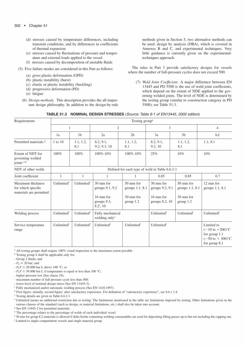
302 • Chapter 51
(d) stresses caused by temperature differences, includingtransient conditions, and by differences in coefficientsof thermal expansion
(e) stresses caused by fluctuations of pressure and temper-ature and external loads applied to the vessel
(f) stresses caused by decomposition of unstable fluids
(5) Five failure modes are considered in this Part as follows:
(a) gross plastic deformation (GPD)(b) plastic instability (burst)(c) elastic or plastic instability (buckling)(d) progressive deformation (PD)(e) fatigue
(6) Design methods. This description provides the all-impor-tant design philosophy. In addition to the design-by-rule
methods given in Section 5, two alternative methods canbe used: design by analysis (DBA), which is covered inAnnexes B and C, and experimental techniques. Verylittle guidance is currently given on the experimental-techniques approach.
The rules in Part 3 provide satisfactory designs for vesselswhere the number of full-pressure cycles does not exceed 500.
(7) Weld Joint Coefficient. A major difference between EN13445 and PD 5500 is the use of weld joint coefficients,which depend on the extent of NDE applied to the gov-erning welded joints. The level of NDE is determined bythe testing group (similar to construction category in PD5500); see Table 51.3.
TABLE 51.3 NOMINAL DESIGN STRESSES (Source: Table 6-1 of EN13445, 2002 edition)
Requirements Testing groupa
1 2 3 4
1a 1b 2a 2b 3a 3b b,I
Permitted materials g 1 to 10 1.1, 1.2, 8.2, 9.1, 1.1, 1.2, 8.2, 9.1, 1.1, 1.2, 1.1, 8.18.1 9.2, 9.3, 10 8.1 9.2, 10 8.1
Extent of NDT for 100% 100% 100%-10% 100%-10% 25% 10% 10%governing welded joints e,h
NDT of other welds Defined for each type of weld in Table 6.6.2-1
Joint coefficient 1 1 1 1 0.85 0.85 0.7
Maximum thickness Unlimitedf Unlimitedf 30 mm for 50 mm for 30 mm for 50 mm for 12 mm forfor which specific groups 9.1, 9.2 groups 1.1, 8.1 groups 9.2, 9.1 groups 1.1, 8.1 groups 1.1, 8.1materials are permitted
16 mm for 30 mm for 16 mm for 30 mm forgroups 9.3, group 1.2 groups 8.2, 10 group 1.28.2i, 10
Welding process Unlimitedf Unlimitedf Fully mechanical Unlimitedf Unlimitedf Unlimitedf
welding onlyc
Service temperature Unlimitedf Unlimitedf Unlimitedf Unlimitedf Unlimitedf Limited torange (�10 to �200)°C
for group 1.1(�50 to � 300)°C for group 8.1
a All testing groups shall require 100% visual inspection to the maximum extent possibleb Testing group 4 shall be applicable only for:- Group 2 fluids; and- PS � 20 bar; and- PSV � 20 000 bar L above 100 °C; or- PSV � 50 000 bar L if temperature is equal or less than 100 °C;- higher pressure test (See clause 10);- maximum number of full pressure cycle less than 500;- lower level of nominal design stress (See EN 13445-3).c Fully mechanized and/or automatic welding process (See EN 1418:1997).d First figure: initially, second figure: after satisfactory experience. For definition of “satisfactory experience”, see 6.6.1.1.4e Testing details are given in Table 6.6.2-1f Unlimited means no additional restriction due to testing. The limitations mentioned in the table are limitations imposed by testing. Other limitations given in thevarious clauses of the standard (such as design, or material limitations, etc.) shall also be taken into account.
g See EN 13445-2 for permitted materials.h The percentage relates to the percentage of welds of each individual vesselI 30 mm for group 8.2 materials is allowed if delta ferrite containing welding consumables are used for depositing filling passes up to but not including the capping run.j Limited to single compartment vessels and single material group.
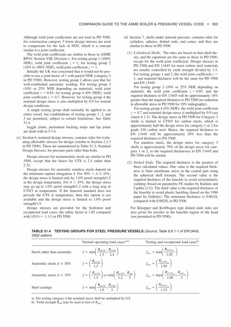
COMPANION GUIDE TO THE ASME BOILER & PRESSURE VESSEL CODE • 303
Although weld joint coefficients are not used in PD 5500,for construction category 3 lower design stresses are usedto compensate for the lack of NDT, which is a conceptsimilar to a joint coefficient.
The weld joint coefficients are similar to those in ASMEBPVC Section VIII, Division 1. For testing group 1 (100%NDE), weld joint coefficient z � 1; for testing group 2(10% to 100% NDE), weld joint coefficient z � 1.
Initially the UK was concerned that it would not be pos-sible to use a joint factor of 1 with partial NDE (category 2in PD 5500). However, testing group 2 allows just that forwell-established automatic welding. For testing group 3(10% or 25% NDE depending on material), weld jointcoefficient z � 0.85; for testing group 4 (0% NDE), weldjoint coefficient z � 0.7. However, for testing group 4 thenominal design stress is also multiplied by 0.9 for normaldesign conditions.
A single testing group shall normally be applied to anentire vessel, but combinations of testing groups 1, 2, and3 are permitted, subject to certain limitations. See Table51.4.
Joggle joints, permanent backing strips and lap jointsare dealt with in 5.7.4.
(c) Section 6, nominal design stresses, contains rules for evalu-ating allowable stresses for design (similar to Section 2.3.3in PD 5500). These are summarized in Table 51.3, NominalDesign Stresses, for pressure parts other than bolts.
Design stresses for nonaustenitic steels are similar to PD5500, except that the factor for UTS is 2.4 rather than2.35.
Design stresses for austenitic stainless steels depend onthe minimum rupture elongation A. For 30% � A � 35%,the design stress is limited only by 1.0% proof strength/1.5at the design temperature. For A � 35%, the design stressmay go up to 1.0% proof strength/1.2 with a long stop ofUTS/3 at temperature. If the material standard does notprovide the UTS at temperature, then this option is notavailable and the design stress is limited to 1.0% proofstrength/1.5.
Design stresses are provided for the hydrotest andexceptional load cases; the safety factor is 1.05 comparedwith 1/0.9 (� 1.11) in PD 5500.
(d) Section 7, shells under internal pressure, contains rules forcylinders, spheres, dished ends, and cones, and they aresimilar to those in PD 5500.
(1) Cylindrical Shells. The rules are based on thin-shell the-ory, and the equations are the same as those in PD 5500,except for the weld joint coefficient. Design stresses inPD 5500 and EN 13445 for most carbon steel materialsare usually controlled by yield strength divided by 1.5.For testing groups 1 and 2, the weld joint coefficient z �1, and required thickness will be the same for PD 5500and EN 13445.For testing group 3 (10% or 25% NDE depending on
material), the weld joint coefficient z � 0.85, and therequired thickness to EN 13445 will be approximately 18%greater than the required thickness to PD 5500 (no reductionin allowable stress in PD 5500 for 10% radiography).
For testing group 4 (0% NDE), the weld joint coefficientz � 0.7 and nominal design stress is multiplied by 0.9 (seeclause 6.1.3). The design stress in PD 5500 for Category 3shells is limited to UTS/5 for carbon steels, which isapproximately half the design stress for category 1 or 2 forgrade 430 carbon steel. Hence, the required thickness toEN 13445 will be approximately 20% less than therequired thickness to PD 5500.
For stainless steels, the design stress for category 3shells is approximately 70% of the design stress for cate-gory 1 or 2, so the required thicknesses to EN 13445 andPD 5500 will be similar.
(2) Dished Ends. The required thickness is the greatest ofthree calculated values. One value is the required thick-ness to limit membrane stress in the central part usingthe spherical shell formula. The second value is therequired thickness of the knuckle to avoid axisymmetricyielding (based on parametric FE studies by Kalnins andUpdike [11]). The third value is the required thickness ofthe knuckle to avoid plastic buckling (based on the 1986paper by Galletly). The minimum thickness is 0.001De
compared with 0.002De in PD 5500.
For Kloepper and Korbbogen type dished ends rules arealso given for nozzles in the knuckle region of the head(not permitted in PD 5500).
TABLE 51.4 TESTING GROUPS FOR STEEL PRESSURE VESSELS (Source: Table 6.6.1-1 of EN13445,2002 edition)
Normal operating load casesa) b) Testing and exceptional load casesb)
Steels other than austenitic
Austenitic steels A � 30%
Austenitic steels A � 35%
Steel castings
a) For testing category 4 the nominal stress shall be multiplied by 0,9b) Yield strength ReH may be used in lieu of Rp0,2
ftest � � Rp0.2/ttest
1.33 �f � min� Rp0.2/t
1.9;
Rm/20
3 �
ftest � max� Rp1.0/ttest
1.05;
Rm/ttest
2 �f � � Rp1.0/t
1.5 � or min� Rp1.0/t
1.2;
Rm/t
3 �
ftest � � Rp1.0/ttest
1.05 �f � � Rp1.0/t
1.5 �
ftest � min� Rp0.2/ttest
1.05 �f � min� Rp0.2/t
1.5;
Rm/20
2.4 �
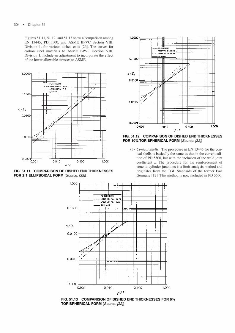
304 • Chapter 51
Figures 51.11, 51.12, and 51.13 show a comparison amongEN 13445, PD 5500, and ASME BPVC Section VIII,Division 1, for various dished ends [26]. The curves forcarbon steel materials to ASME BPVC Section VIII,Division 1, include an adjustment to incorporate the effectof the lower allowable stresses to ASME.
(3) Conical Shells. The procedure in EN 13445 for the con-ical shells is basically the same as that in the current edi-tion of PD 5500, but with the inclusion of the weld jointcoefficient z. The procedure for the reinforcement ofcone to cylinder junctions is a limit-analysis method andoriginates from the TGL Standards of the former EastGermany [12]. This method is now included in PD 5500.
FIG. 51.11 COMPARISON OF DISHED END THICKNESSESFOR 2:1 ELLIPSOIDAL FORM (Source: [32])
FIG. 51.12 COMPARISON OF DISHED END THICKNESSESFOR 10% TORISPHERICAL FORM (Source: [32])
FIG. 51.13 COMPARISON OF DISHED END THICKNESSES FOR 6%TORISPHERICAL FORM (Source: [32])
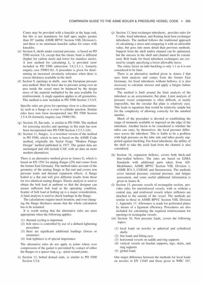
COMPANION GUIDE TO THE ASME BOILER & PRESSURE VESSEL CODE • 305
Cones may be provided with a knuckle at the large end,but this is not mandatory for half apex angles greaterthan 30° (unlike ASME BPVC Section VIII, Division1),and there is no minimum knuckle radius for cones withknuckles.
(e) Section 8, shells under external pressure, is based on PD5500 section 3.6, except that the elastic limit is different(higher for carbon steels and lower for stainless steels).A new method for calculating Le is provided (nowincluded in PD 5500 subsection 3.6.2.3.1.1, formerlyenquiry case 5500/116). A procedure is given for deter-mining an increased circularity tolerance when there isexcess thickness available in the shell.
(f) Section 9, openings in shells, uses the European pressurearea method. Here the force due to pressure acting over anarea inside the vessel must be balanced by the designstress of the material multiplied by the area available forreinforcement. A single equation applies to all geometries.This method is now included in PD 5500 Section 3.5.4.9.
Specific rules are given for openings close to a discontinu-ity such as a flange or a cone to cylinder junction. Similarrules have now been incorporated into PD 5500 Section3.5.4.10 (formerly enquiry case 5500/130).
(g) Section 10, flat ends, is similar to PD 5500. The methodfor assessing nozzles and openings in flat ends has nowbeen incorporated into PD 5500 Section 3.5.5.3.1(b).
(h) Section 11, flanges, is a rewritten version of the methodin PD 5500, which in turn is based on the ASME Codemethod, originally the Taylor Forge “Modern FlangeDesign” method published in 1937. The gasket data areunchanged and still include CAF, with no data on moremodern alternatives.
There is an alternative method given in Annex G, which isbased on EN 1591 for piping flanges [29] and comes fromthe former East Germany. The method takes account of thegeometry of the mating flange or flat end and covers nonpressure loads and thermal expansion effects. A flangebolted to a flat end will give different results from thosefor two identical mating flanges. Elastic analysis is used toobtain the bolt load at ambient so that the designer canensure sufficient bolt load at the operating condition.Scatter of bolt load at bolting up is a major consideration.A limit analysis is used to check loadings in the flange.
The calculations require much iteration, and even chang-ing the flange thickness means that the whole calculationhas to be restarted.
It is worth noting that the alternative rules are mostappropriate when the following applies:
(1) thermal cycling is important(2) bolt stress is controlled by use of a defined tightening
procedure(3) there are significant additional loadings (forces or
moments)(4) leak tightness is of special importance
The alternative rules do not apply to joints where overcompression of the gasket is prevented by contact of eitherthe flanges or a spacer ring, e.g., spiral wound joints.
(i) Section 12, bolted domed ends, is similar to PD 5500Section 3.5.6.
(j) Section 13, heat exchanger tubesheets, provides rules forU-tube, fixed tubesheet, and floating head heat exchangertubesheets. The method follows the traditional approachof calculating a stress and comparing it with an allowablevalue, but goes into more detail than previous methods.Support from the shell and/or channel can be optimized,but the stresses in the shell and channel must be consid-ered. Bolt loads for fixed tubesheet exchangers are cov-ered by simply specifying a lower allowable stress.The safety factor on tube buckling is only 1.1 as it is not
considered to be fatal.There is an alternative method given in Annex J that
uses limit analysis and comes from the former EastGermany; for fixed tubesheets without bellows, it is alsonecessary to calculate stresses and apply a fatigue failurecriterion.
The method is built around the limit analysis of thetubesheet as an axisymmetric flat plate. Limit analysis ofpressure vessel components is often difficult, or nearlyimpossible, but the circular flat plate is relatively easy.This leads to equations that would be relatively simple butfor the complexity of allowing correctly for the untubedannulus.
Much of the procedure is devoted to establishing therange of moments available or imposed on the edge of thetubesheet. Another factor to be considered is whether thetubes can carry, by themselves, the local pressure differ-ence across the tubesheet. This is liable to be a problemwith high pressure on the tube side and tubes poorly sup-ported against buckling. For fixed tubesheets, the ability ofthe shell to take the axial load from the channel is alsoconsidered.
(k) Section 14, expansion bellows, covers both thick-andthin-walled bellows. The rules are based on EJMAStandards with additional parts taken from AD-Merkblatter, ASME BPVC Section VIII, Division 1,ASME B31.3, CODAP, and Stoomwezen. The methodscover internal pressure, external pressure, and fatigueassessment, and some useful additional information isgiven in Annex K.
(l) Section 15, pressure vessels of rectangular section, pro-vides rules for unreinforced vessels, with or without acentral stay, and reinforced vessels where stiffeners areattached to the outside of the vessel. The methods aresimilar to those in ASME BPVC Section VIII, Division1, Appendix 13. Allowance is made for perforated platesby means of a ligament efficiency. Procedures are alsoincluded for calculating the required reinforcement foropenings in rectangular vessels.
(m) Section 16, Non pressure loads, covers the followingtopics:
(1) local loads on nozzles in spherical and cylindricalshells
(2) line loads and lifting eyes(3) horizontal vessels on saddle and ring supports(4) vertical vessels on bracket supports, legs, skirts, and
ring supports(5) global loads
One major difference between the methods for local loadson nozzles in EN 13445 and those given in WRC 107,

306 • Chapter 51
WRC 297, or PD 5500 Annex G, is that in EN 13445 localloads are assessed by comparing them with maximumallowable loads based on a limit load analysis, in additionto calculating stresses and comparing these with allowablestresses.A major advantage for the designer is that there are con-siderably fewer charts and tables in EN 13445 comparedwith the other methods, and equations are given for eachof the curves for use in computer programs or spread-sheets. PD 5500 Annex G, Section G.2.8 (formerlyenquiry case 5500/122) now includes alternative methodsfor analyzing local loads on nozzles in cylindrical andspherical shells based on EN 13445.
The method for line loads comes from East Germany;simple allowable load equations are combined with abending limit stress that allows for pressure and globalloads. A procedure is given for the evaluation of allowableloads on lifting eyes (lifting lugs).
The rules for saddle supports are based on a limit loadanalysis and are quite different from those in PD 5500(which are based on the Zick method). The method in EN13445 requires a geometry configuration to be given and alimit load evaluated. This requires various formulae to becalculated and the evaluation of several factors fromgraphs.
For vertical vessels EN 13445 contains design methodsfor vertical vessels on bracket supports (section 16.10),vertical vessels on leg supports (section 16.11), verticalvessels with skirts (section 16.12), and vertical vesselswith ring supports (section 16.13). Sections 16.10 and16.11 only cover assessment of support loadings in theshell or head and do not cover the design of the actualbrackets or legs. Section 16.12 includes design proceduresfor skirts, including the effects of skirt openings and skirt-to-vessel attachment. Section 16.13 includes proceduresfor the design of ring supports.
(n) Section 17, simplified assessment of fatigue life, givesrules for simplified fatigue assessment for pressure loadingonly.
(o) Section 18, detailed assessment of fatigue life, providesrules for detailed fatigue assessment for pressure vesselsand components subject to stress fluctuations.
Both fatigue sections are based on the method in PD 5500Annex C with additional refinements.
Ten separate fatigue design curves are provided for differentweld categories, compared with seven in PD 5500. In addition, afatigue curve is given for unwelded material, together with corre-sponding rules.
51.3.4 Part 4, ManufactureThis part covers requirements for material traceability and
marking, manufacturing tolerances, acceptable weld details, weld-ing, NDE personnel, production testing, postweld heat treatment,and repairs.
51.3.5 Part 5, Inspection and TestingThis part covers requirements for design documentation,
inspection and testing during fabrication, final assessment, mark-ing and declaration of conformity with the standard, and files tobe compiled (records).
For testing groups 1, 2, and 3, the standard hydraulic test pres-sure is the higher of the following:
51.3.6 New DevelopmentsThere have been several minor revisions to EN 13445 to correct
various errors in the standard, and there is a considerable programof work to cover areas not yet included in the current edition,including the following:
(a) aluminium vessels(b) reinforced and toroidal bellows(c) experimental design methods(d) creep(e) austenitic nodular cast irons(f) stiffened flat walls
A new edition of EN 13445 is planned for 2006. Further guid-ance on the use of EN 13445 can be found elsewhere [32]. Furtherbackground in formation on PD 5500 can be found [33].
A document entitled EN 13445, Unfired Pressure Vessels,Background to the rules in Part 3: Design [34] has been producedby Guy Baylac and Danielle Koplewicz. This is available fordownloading from the EN 13445 help desk Web site atwww.unm.fr/en/general/en13445/.
51.4 REFERENCES
1. BS 5500, Unfired Fusion-Welded Pressure Vessels. British StandardsInstitution; 1976–2000.
2. BS 1500, Specification for Fusion-Welded Pressure Vessels forGeneral Purposes. British Standards Institution; 1965.
3. BS 1515, Part 1, Specification for Fusion-Welded Pressure Vessels.British Standards Institution; 1968.
4. Draft International Standard ISO/DIS2694, published by ISO, 1973.
5. EN 13445, Unfired Pressure Vessels. CEN, 2002.
6. European Pressure Equipment Directive (PED) 97/23/EC, 1997.
7. Pressure Equipment Regulations 1999 (SI 1999/2001, Department ofTrade and Industry, London, 1999.
8. BS EN 287, Qualification Test of Welders. Fusion Welding Steels.British Standards Institution; 2004.
9. BS EN 288, Specification and Approval of Welding Procedures forMetallic Materials. British Standards Institution; 2004.
10. ASME BPVC Section VIII. In: ASME Boiler and Pressure VesselCode. New York: American Society of Mechanical Engineers.
11. Kalnins A, Updike DP. New Design Curves for Torispherical Heads(Bulletin 364). Welding Research Council; 1991.
12. Fachbereitstandard, Behalter und Apparate, Festigskeitsberechnung,Kegelschalen, TGL32903/06. Standardsversand, Leipzig, April 1989.
13. PD 6550, Explanatory Supplement to BS 5500:1988. Specification forUnfired Fusion-Welded Pressure Vessels: Section 3, Design. VesselsUnder External Pressure. British Standards Institution; 1989.
14. Kendrick S. Design for External Pressure Using General Criteria.International Journal of Mechanical Science 1982;24(4):209–218.
15. CODAP, French Code for the Construction of Pressure Vessels. Editedby SNCT and AFIAP.
pt � 1.25pd fa
ft
or pt � 1.43pd

COMPANION GUIDE TO THE ASME BOILER & PRESSURE VESSEL CODE • 307
16. Macfarlane WA, Findlay GE. A Simple Technique for CalculatingShakedown Loads in Pressure Vessels. Proceedings IMechE1972;186(4):45–52.
17. AD-Merkblätter Berechnung von Druckbehältern.
18. Waters EO, Wesstrom DB, Rossheim DB, Williams FSG. Formulasfor Stresses in Bolted Flange Connections. Transactions ASME1937;59:161.
19. Young WC, Roark RC. Roark’s Formulas for Stress and Strain (6thEdition). London: McGraw-Hill Publishers; 1989.
20. PD 6497, Stresses in Horizontal Cylindrical Pressure Vessels Supportedon Twin Saddles: a Derivation of the Basic Equations and ConstantsUsed in G3.3 of BS 5500. British Standards Institution; 1982.
21. Zick LP. Stresses in Large Horizontal Cylindrical Pressure Vessels onTwo Saddle Supports. Welding Research Journal (Supplement) 1951.
22. Tooth AS, Duthie G, White GC, Carmichael J. Stresses in HorizontalStorage Vessels: A Comparison of Theory and Experiment. Journal ofStrain Analysis 1982;17:169–176.
23. Tooth AS, Nash DH. Stress Analysis and Fatigue Assessment of TwinSaddle Supported Pressure Vessels. PVP Vol. 217, Pressure Vesselsand Components, ASME Conference, June 1991, pp 41–48.
24. Tooth AS. Local Loads, Supports, and Mounting (Chapter 4). In:Pressure Vessel Design – Concepts and Principles. Eds. Spence J,Tooth AS, E and F N Spon; 1994.
25. Tooth AS, Nash DH. The Use of Microcomputer in the Design ofCylindrical Pressure Vessels. International Journal of PressureVessels and Piping 1986.
26. Wichman KR, Hopper AG, Mershon JL. Local Stresses in Sphericaland Cylindrical Shells Due to External Loadings (Bulletin 107).Welding Research Council; 1979.
27. Leckie FA, Penny RK. (1) A Critical Study of the Solutions for theAsymmetric Bending of Spherical Shells; (2) Solutions for theStresses at Nozzles in Pressure Vessels; and (3) Stress ConcentrationFactors for the Stresses at Nozzle Intersections in Pressure Vessels(Bulletin 90). Welding Research Council; 1963.
28. Peterson RE. Stress Concentration Factors. John Wiley & Sons;1974.
29. EN 1591, Flanges and Their Joints. Design Rules for GasketedCircular Flange Connections. Calculation method, CEN, 2001.
30. PD 6550, Explanatory Supplement to BS 5500:1988. Specification forUnfired Fusion-Welded Pressure Vessels: Section 3, Design. HeatExchanger Tubesheets. British Standards Institution; 1989.
31. Earland SW, Nash DH. European Pressure Equipment, the PED andEN 13445, Course Notes. Glasgow: The University of Strathclyde;2004.
32. Earland SW, Nash DH, Garden W. Guide to European PressureEquipment. PEP, 2003.
33. Nichols RW. Pressure Vessel Codes and Standards. Elsevier AppliedScience; 1987.
34. Baylac G, Koplewicz D. EN 13445, Unfired Pressure Vessel.Background to the Rules in Part 3: Design. Available at:www.unm.fr/en/general/en13445.
