chapter 6
DESCRIPTION
Chapter 6. Digital Data Communications Techniques. Asynchronous and Synchronous Transmission 1. We are concerned with serial transmission of data, I.e. transmission over a single path rather than parallel set of lines Signals are sent down the line one at a time each containing - PowerPoint PPT PresentationTRANSCRIPT
TUNALI Data Communication 1
Chapter 6
Digital Data Communications Techniques
TUNALI Data Communication 2
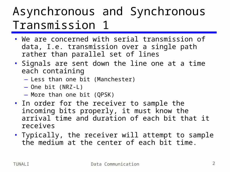
Asynchronous and Synchronous Transmission 1• We are concerned with serial transmission of
data, I.e. transmission over a single path rather than parallel set of lines
• Signals are sent down the line one at a time each containing—Less than one bit (Manchester)—One bit (NRZ-L)—More than one bit (QPSK)
• In order for the receiver to sample the incoming bits properly, it must know the arrival time and duration of each bit that it receives
• Typically, the receiver will attempt to sample the medium at the center of each bit time.
TUNALI Data Communication 3
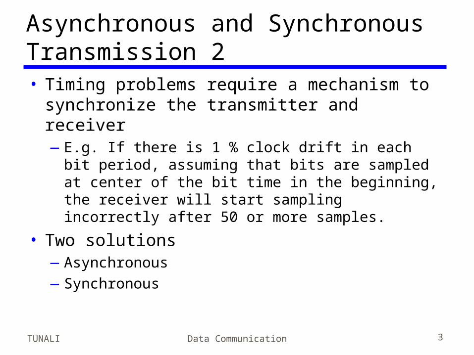
Asynchronous and Synchronous Transmission 2• Timing problems require a mechanism to
synchronize the transmitter and receiver—E.g. If there is 1 % clock drift in each bit
period, assuming that bits are sampled at center of the bit time in the beginning, the receiver will start sampling incorrectly after 50 or more samples.
• Two solutions—Asynchronous—Synchronous

TUNALI Data Communication 4
Asynchronous• Data are transmitted one character at a
time—5 to 8 bits
• Timing only needs maintaining within each character
• Resynchronize with each character

TUNALI Data Communication 5
Rules• When no characters are transmitted, the line
is idle, that is equivalent to signaling element 1.
• NRZ-L is common in asynchronous transmission
• The beginning of a character is signaled by a start bit with a value of binary zero.
• The bits of the character are sent beginning with the least significant bit. This is followed by the parity bit.
• Then the stop bit is sent (binary 1). There is a minimum duration specified for the stop bit.

TUNALI Data Communication 6
Asynchronous (diagram)
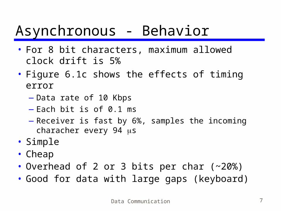
Asynchronous - Behavior• For 8 bit characters, maximum allowed clock
drift is 5%• Figure 6.1c shows the effects of timing error
—Data rate of 10 Kbps—Each bit is of 0.1 ms—Receiver is fast by 6%, samples the incoming
characher every 94 s • Simple• Cheap• Overhead of 2 or 3 bits per char (~20%)• Good for data with large gaps (keyboard)
Data Communication 7
TUNALI Data Communication 8
Async. Trans. Cont.• Two errors:1.The character is incorrectly received2.The bit count is out of alignment (framing
error)— if bit 7 is a 1 and bit 8 is a 0, bit 8 could be
mistaken for a start bit— Framing error can also occur if some noise
condition causes the false appearance of a start bit during the idle state
TUNALI Data Communication 9
Synchronous - Bit Level• Block of data transmitted without start or stop
bits• Clocks must be synchronized• Can use separate clock line, one side pulses the
line regularly with one short pulse per bit time—Good over short distances—Subject to impairments
• Embed clock signal in data—Manchester encoding—Carrier frequency (analog): synchronize the receiver
based on the phase of the carrier
TUNALI Data Communication 10
Sync. Tran. Cont’d.• There should be a second level of
synchronization to allow receiver recognize the beginning and end of block data.
• To achieve this, a special bit pattern is used.
TUNALI Data Communication 11
Synchronous - Block Level• Need to indicate start and end of block• Use preamble and postamble
—The frame starts with a preamble called a flag, 8 bits long
—Same flag is used as a postamble
• More efficient (lower overhead) than async

TUNALI Data Communication 12
Synchronous (diagram)
TUNALI Data Communication 13
Example• HDLC contains 48 bits of control,
preamble and postamble.• Thus, for 1000-character block of data,
each frame consists of 48 bits of overhead, 1000x8=8000 bits of data yielding 48/8048=0.6% percentage overhead which is much lower than that of asynchronous transmission
TUNALI Data Communication 14
Types of Error• An error occurs when a bit is altered between
transmission and reception• Single bit errors
—One bit altered—Adjacent bits not affected—White noise
• Burst errors—Length B—Contiguous sequence of B bits in which first last and any
number of intermediate bits in error—Impulse noise, Fading in wireless—For data rate of 10 Mbps, 1 s impulse noise event or
fading event : error bursts of 10 bits —Effect greater at higher data rates

TUNALI Data Communication 15
Error Detection MotivationDefinePb = probability of a single bit error
P1 = probability that a frame arrives with no bit errors
P2 = probability that a frame arrives with one or more undetected bit errors
F = number of bits in a frame
P1 = (1 - Pb) F and P2 = 1 - P1

TUNALI Data Communication 16
ExampleOn 64 kbps ISDN channel Pb=10-6. At most one
frame of length 1000 bits can be allowed to have undetected bit error per day.
Let us see how this compares with the result of BER of 10-6:
# frames in a day = 5.529 106
P2 = 1 / (5.529 106) = 0.18 10-6 = acceptableCompare this to
P2 = 1- P1 = 1 – (1 – Pb)F = 1 – (1-10-6)1000 = 10-3
Conclusion:Unacceptable error rate! Do something
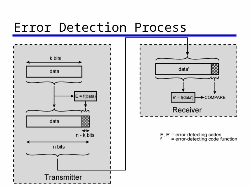
Error-Detecting Code• Additional bits added by transmitter for error
detection code (error-detection code)• For a data block of k bits transmitter
generates error detection code of n-k bits, n-k<k
• Transmit n bits• Receiver seperates frame into k bits data and
(n-k) bits of error detection code, performs same calculation
• A detected error occurs if there is a mismatch
TUNALI Data Communication 17
TUNALI Data Communication 18
Error Detection Process

TUNALI Data Communication 19
Parity Check• Simplest error detection code is to append
a parity bit• Parity
—Value of parity bit is such that character has even (even parity) or odd (odd parity) number of ones
—Even number of bit errors goes undetected

Parity Check - Example• Transmitter transmits IRA character G
(1110001)• Using odd parity, it will append a 1 and
transmit 11110001• The receiver assumes no error has
occured if the total no of 1s is odd• if one bit (or any odd no of bits) is
erroneously converted, the receiver will detect an error
TUNALI Data Communication 20

TUNALI Data Communication 21
Cyclic Redundancy Check• For a block of k bits transmitter generates
n-k bit sequence known as Frame Check Sequence (FCS)
• Transmit n bits which is exactly divisible by some number
• Receiver divides frame by that number—If no remainder, assume no error—For math, see Stallings chapter 6
TUNALI Data Communication 22
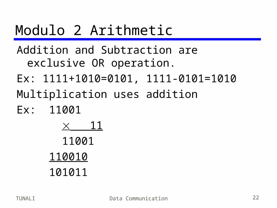
Modulo 2 ArithmeticAddition and Subtraction are exclusive OR
operation.Ex: 1111+1010=0101, 1111-0101=1010Multiplication uses additionEx: 11001 11 11001 110010 101011
TUNALI Data Communication 23
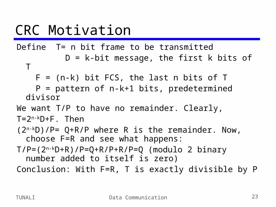
CRC MotivationDefine T= n bit frame to be transmitted
D = k-bit message, the first k bits of T F = (n-k) bit FCS, the last n bits of T P = pattern of n-k+1 bits, predetermined
divisorWe want T/P to have no remainder. Clearly,T=2n-kD+F. Then(2n-kD)/P= Q+R/P where R is the remainder. Now,
choose F=R and see what happens:T/P=(2n-kD+R)/P=Q+R/P+R/P=Q (modulo 2 binary
number added to itself is zero)Conclusion: With F=R, T is exactly divisible by P
TUNALI Data Communication 24
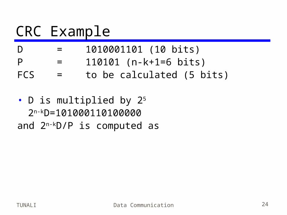
CRC ExampleD = 1010001101 (10 bits)P = 110101 (n-k+1=6 bits)FCS = to be calculated (5 bits)
• D is multiplied by 25
2n-kD=101000110100000 and 2n-kD/P is computed as

CRC Example
Data Communication 25

TUNALI Data Communication 26
CRC Example (cont’d)Hence T=2n-kD+R=101000110101110 which
is transmitted.
If there are no errors, the receiver receives T intact. Dividing T by P yields no remainder.
If there are errors, what receiver receives is not T and dividing by P yields a remainder and receiver concludes that an error has occurred.

TUNALI Data Communication 27
CRC Polynomials• Each binary number can be viewed as
coefficients of a polynomial with a dummy variable X.
• E.g. For M=110011 M(X)=X5+X4+X+1• Popular polynomials used in practice are
—CRC-12 = X12 + X11 + X3 + X + 1—CRC-16 = X16 + X15 + X2 + 1—CRC-CCITT = X16 + X12 + X5 + 1—CRC-32 = too long, check the book
TUNALI Data Communication 28
Error Correction• Correction of detected errors usually requires
data block to be retransmitted (see chapter 7)
• Not appropriate for wireless applications—Bit error rate is high
• Lots of retransmissions
—Propagation delay can be long (satellite) compared with frame transmission time
• Would result in retransmission of frame in error plus many subsequent frames
• Need to correct errors on basis of bits received
TUNALI Data Communication 29
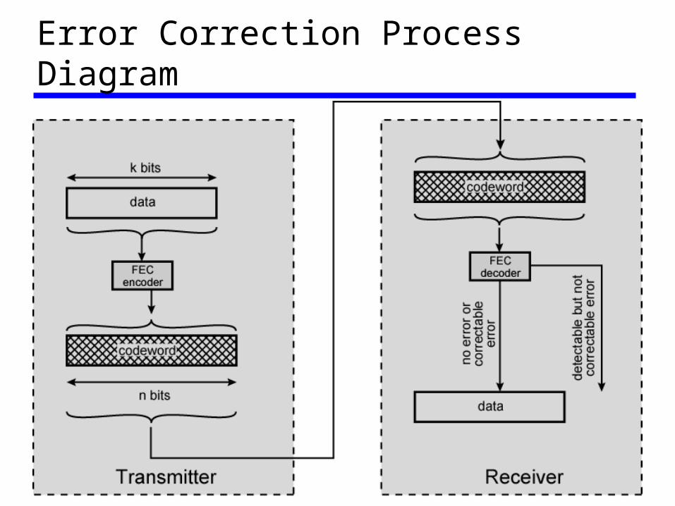
Error Correction Process Diagram

TUNALI Data Communication 30
Error Correction Process• Each k bit block mapped to an n bit block (n>k)
—Codeword—Forward error correction (FEC) encoder
• Codeword sent• Received bit string similar to transmitted but may
contain errors• Received code word passed to FEC decoder
—If no errors, original data block output—Some error patterns can be detected and corrected—Some error patterns can be detected but not corrected—Some (rare) error patterns are not detected
• Results in incorrect data output from FEC
TUNALI Data Communication 31
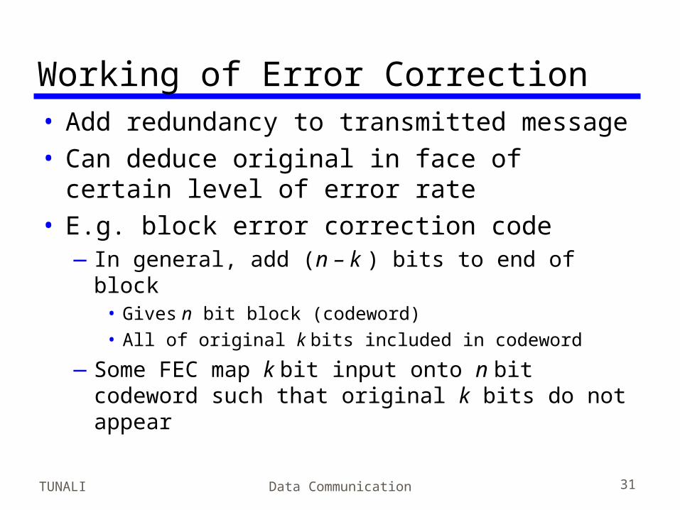
Working of Error Correction• Add redundancy to transmitted message• Can deduce original in face of certain level
of error rate• E.g. block error correction code
—In general, add (n – k ) bits to end of block• Gives n bit block (codeword)• All of original k bits included in codeword
—Some FEC map k bit input onto n bit codeword such that original k bits do not appear
Data Communication 32
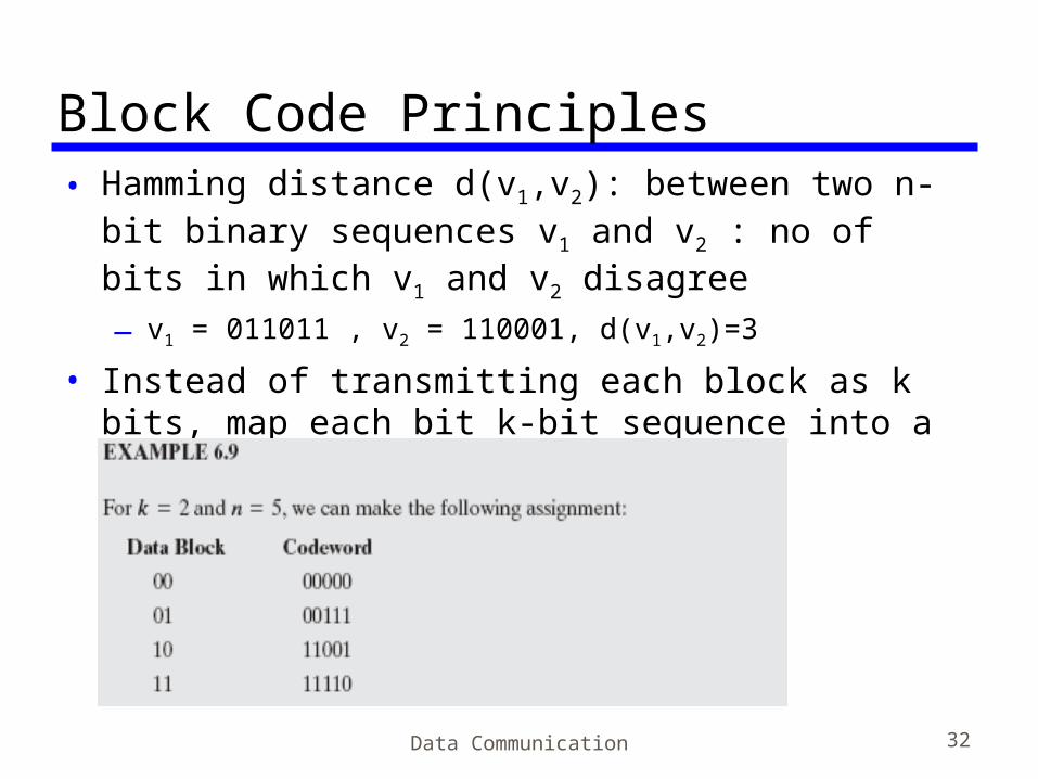
Block Code Principles• Hamming distance d(v1,v2): between two n-bit
binary sequences v1 and v2 : no of bits in which v1 and v2 disagree—v1 = 011011 , v2 = 110001, d(v1,v2)=3
• Instead of transmitting each block as k bits, map each bit k-bit sequence into a unique n-bit codeword

Example• Suppose a codeword is received with bit
pattern 00100• In terms of Hamming distances, we have
• If an invalid codeword is received, the valid code with min distance is selected
• What if there is more than one valid code at a minimum distance?
Data Communication 33
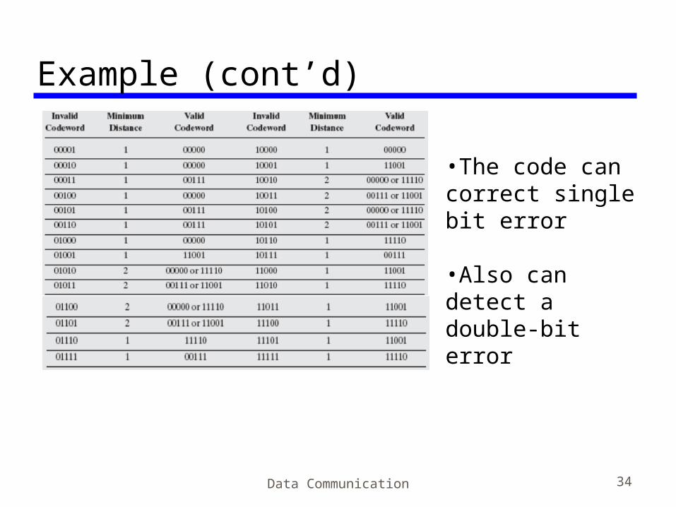
Example (cont’d)
Data Communication 34
•The code can correct single bit error
•Also can detect a double-bit error
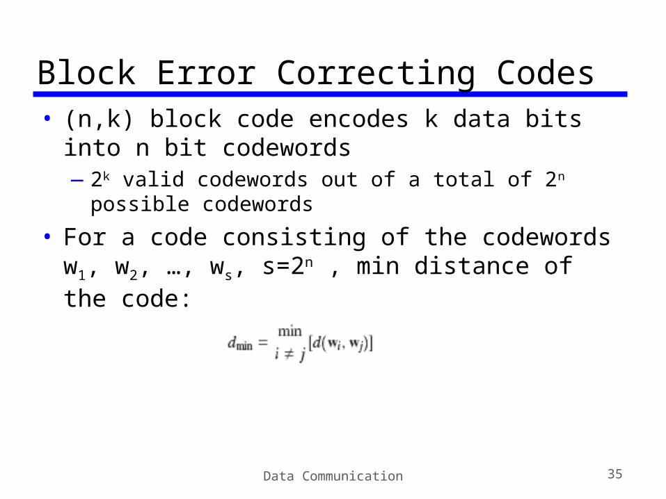
Block Error Correcting Codes• (n,k) block code encodes k data bits into n
bit codewords—2k valid codewords out of a total of 2n possible
codewords
• For a code consisting of the codewords w1, w2, …, ws, s=2n , min distance of the code:
Data Communication 35
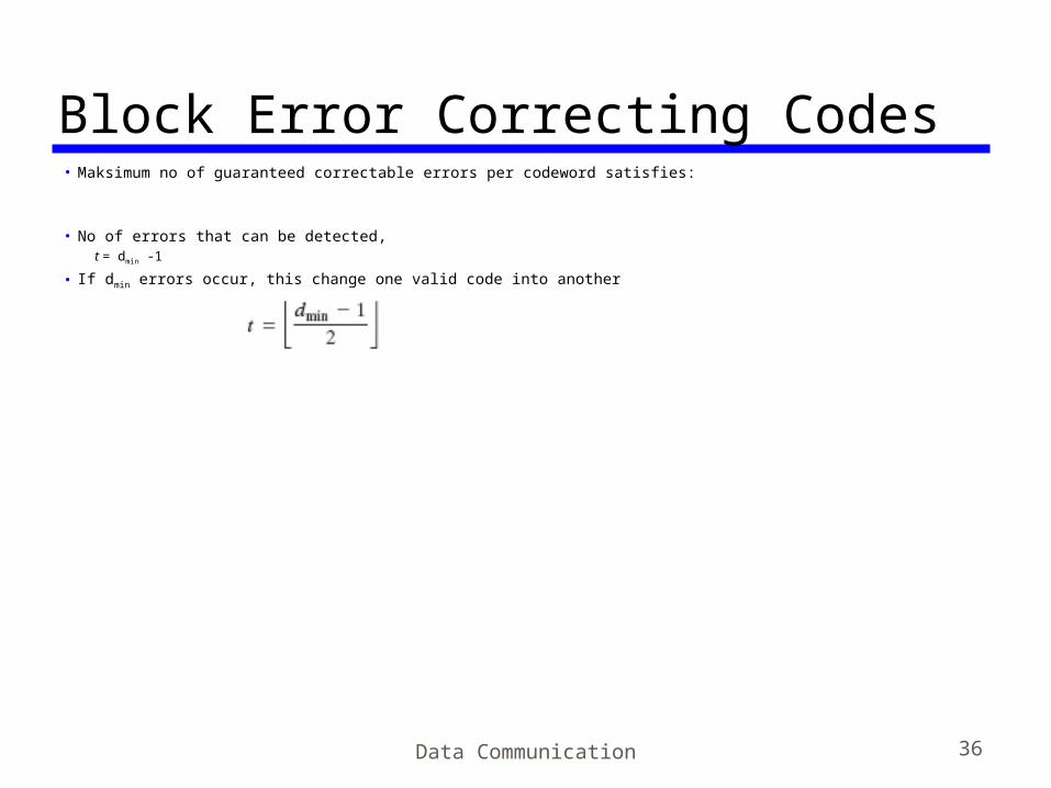
Block Error Correcting Codes• Maksimum no of guaranteed correctable errors per codeword satisfies:
• No of errors that can be detected,t = dmin -1
• If dmin errors occur, this change one valid code into another
Data Communication 36
Block Code Design• Design of a block code involves some
considerations:—Largest possible value of dmin
—Relatively easy encode and decode—(n-k) to be small, to reduce bandwidth—(n-k) to be large, to reduce error rate
TUNALI Data Communication 37

TUNALI Data Communication 38
Line Configuration• Topology
—Physical arrangement of stations on medium—Point to point—Multi point
• Computer and terminals, local area network
• Advantages of multipoint configuration—the computer needs only a single I/O port and—a single transmission line, which saves cost

TUNALI Data Communication 39
Traditional Configurations

Line Configuration• Half duplex
—Only one station may transmit at a time—Requires one data path—Often used for terminal-to-computer
interaction
• Full duplex—Simultaneous transmission and reception
between two stations—Requires two data paths (or echo canceling)—Used for computer-to-computer data exchange
TUNALI Data Communication 40
TUNALI Data Communication 41
Line Conf. Cont’d• For analog signaling, if station operates on
only one frequency, then it must use half duplex.
• If it uses two frequencies, then it may send on one frequency and receive on the other (either guided or unguided media)
• Digital signaling requires guided transmission. Hence, full duplex operation requires two different transmission paths, while half duplex transmission requires only one transmission path.

TUNALI Data Communication 42
Foreground Reading• Stallings chapter 6