chapter 6 anti-vignetting — balancing uneven illumination · 102 chapter 6 anti-vignetting —...
TRANSCRIPT
99
Chapter 6Anti-Vignetting — Balancing Uneven Illumination
In the previous Chapter, we discussed various sourcesof noise and explored some techniques to reduce ran-dom, background noise by stacking images. Now wewill turn our attention to one of the principal sources ofnon-random noise — uneven field illumination.
Virtually all photographic images, regardless ofthe capture source or optical system used, exhibit dif-ferences in background illumination across the field ofview. This holds true for “normal” daylight photo-graphs as well as for astrophotographs. Since mostdaylight images are relatively bright, however, the ef-fect is generally not noticeable. But small differencesin luminosity become readily apparent when setagainst the near black background sky of an astropho-tograph.
Uneven illumination is caused by many factors.Almost all lens/telescope systems exhibit light falloffto some degree. This manifests itself as a circular pat-
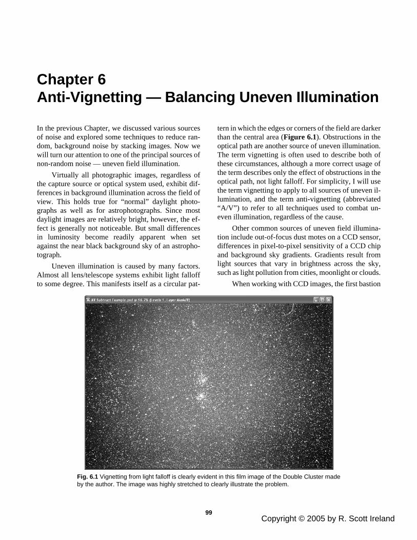
tern in which the edges or corners of the field are darkerthan the central area (Figure 6.1). Obstructions in theoptical path are another source of uneven illumination.The term vignetting is often used to describe both ofthese circumstances, although a more correct usage ofthe term describes only the effect of obstructions in theoptical path, not light falloff. For simplicity, I will usethe term vignetting to apply to all sources of uneven il-lumination, and the term anti-vignetting (abbreviated“A/V”) to refer to all techniques used to combat un-even illumination, regardless of the cause.
Other common sources of uneven field illumina-tion include out-of-focus dust motes on a CCD sensor,differences in pixel-to-pixel sensitivity of a CCD chipand background sky gradients. Gradients result fromlight sources that vary in brightness across the sky,such as light pollution from cities, moonlight or clouds.
When working with CCD images, the first bastion
Fig. 6.1 Vignetting from light falloff is clearly evident in this film image of the Double Cluster madeby the author. The image was highly stretched to clearly illustrate the problem.
Copyright © 2005 by R. Scott Ireland

100 Chapter 6 Anti-Vignetting — Balancing Uneven Illumination
Photoshop Astronomy
against vignetting, as always, is to carefully calibratethe images using dark frames and flat field frames. Buteven after careful flat-fielding, uneven illuminationmay still appear, particularly in the form of linear gra-dients caused by sky glow.
In order to combat vignetting, we need to employa new set of techniques. Stacking will not work, sincevignetting is not random noise. Uneven illuminationwill generally appear in the same place from frame toframe, so stacking will increase this non-random noisein the same manner as the signal. In fact, some wouldsay that non-random noise is signal. It is just a part ofthe signal that we do not wish to keep in our final im-age!
In essence, A/V techniques are just another formof flat-fielding. Our goal is to create a customized flat-field frame that takes into account the conditionspresent on a given night, at a given moment, using aparticular array of equipment to image a particular areaof sky. One of the simplest ways to accomplish this isto use the information that is already contained withinthe image itself. Let me restate and generalize this veryimportant concept;
Whenever possible, let the image do the work for you.
What does this mean, exactly? In the case of A/V,it means using the vignetting pattern in the image itselfto create a “map”, or mask, of the uneven illumination.This mask is then subtracted from the image to balancethe luminosity. We cannot divide the A/V mask intothe image, as we would with a CCD flat-field frame,since Photoshop does not offer us a way to performpixel division. However, we can make do with subtrac-tion, since it is essentially the same process. The ApplyImage or Calculations commands can be used to per-form pixel subtraction directly (the “Subtraction Meth-od”). Or, we may balance illumination by adding an A/V mask into the image layer stack (the “A/V LayerMask method”).
Sometimes an image contains large or complexsubject matter that makes it difficult or impossible toextract an adequate A/V mask directly from the image.In such cases, we may create a “synthetic” A/V maskusing Photoshop’s Gradient Tool (the “Synthetic Maskmethod”).
We will explore each of these techniques in thefollowing examples. As with any mask in Photoshop,an A/V mask may be edited and fine-tuned until itachieves the desired result. This is one reason why
masking is such a powerful and useful technique tomaster. In this chapter, you will have the opportunity tofurther expand upon your masking knowledge, the ap-plication of which extends to countless other areas ofimage processing as well.
Where does A/V fit into the image-processingworkflow? Ideally, A/V should be applied early in theprocess, right after stacking. When images are stackedusing the Average or Addition methods, vignetting isnot altered significantly in the final stack. It is averagedin the same manner as the other signals. Therefore, it isgenerally unnecessary to perform A/V on the individu-al frames prior to stacking. An exception to this is whenthe individual images exhibit different vignetting char-acteristics, such as a sky gradient that changes betweenexposures, or when combining images taken on differ-ent nights. In these cases, it may be desirable to balancethe illumination of the individual frames prior to stack-ing.
While we are on the subject, this is another reasonwhy stacking images using hybrid methods, such asmultiplication, may be undesirable. An unintendedconsequence is enhancement of the brightness differ-ences across the frame, exaggerating vignetting and re-quiring stronger A/V processing.
The Subtraction Method — Introduction to Cloning
OK, let’s get down to work! We will start with the Sub-traction A/V method, which directly subtracts the A/Vmask pixels from the base image using the Apply Im-age command.
1. From the tutorial disc, open the file “AV BaseImage.tif” (File|Open). This is a widefield shot ofthe Double Cluster in Perseus. I used a 300mmcamera lens to take this film image, and thevignetting pattern (light falloff at the edges of thefield) is readily apparent since I used the lens at itswidest aperture.
2. Duplicate the image with Image|Duplicate andclick OK. A new image, “AV Base Image copy”appears on the screen. We will use this image tocreate our A/V mask.
3. Make AV Base Image copy the active image win-dow and open Filter|Blur|Gaussian Blur. Set theRadius to 90 pixels and make sure the Previewbox is checked. Do not click OK yet. The imagenow looks like Figure 6.2. Notice what has hap-

The Subtraction Method — Introduction to Cloning 101
R. Scott Ireland
pened. By selecting a wide blur radius, all of theindividual stars have disappeared and “blended”into the background. What remains is a broad, softrendition of the overall field illumination. The vi-gnetting pattern is clearly evident, but we havehandily eliminated the details, except for one area.The center of the image has two “hot spots”, theDouble Cluster itself. If we eliminate these hotspots, we should have an excellent A/V mask.
4. Click Cancel to close the Gaussian Blur dialogbox without applying the filter. Select the CloneStamp Tool from the Toolbox (keyboard shortcut“S”). This tool used to be called the Rubber StampTool, but since everyone else on the planet calledit the Clone Tool, the Photoshop guys finally ac-quiesced and changed its name (they couldn’t re-sist leaving the “Stamp” in though). Using theClone Stamp Tool starts with the user placing a“sampling point” in the image. As the mouse isthen moved around in the image, the samplingpoint moves with it synchronously. When the leftmouse button is clicked and held, the area underthe sampling point is copied to the new mouse lo-cation. Why is this good? Because it lets us sam-
ple areas very close to the objects we want toeliminate. The cloned areas thereby remainsmooth, without obvious artifacts, since the colorsand luminosities of the sampled areas are verynearly the same as the areas being replaced. Thesecret to good cloning technique is to continuous-ly set new sampling points and keep those pointsvery close to the areas being cloned. This is muchharder to describe than it is to do. Once learned,cloning can be done very quickly.
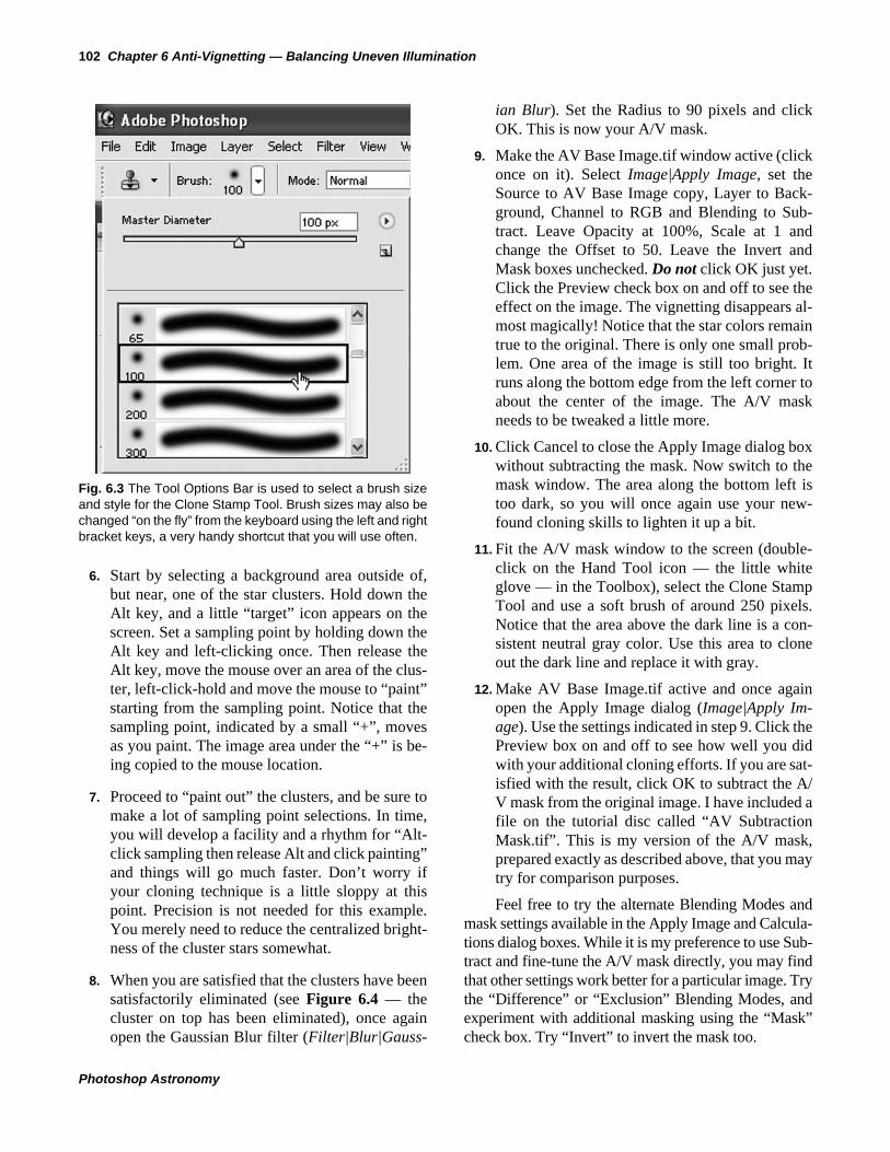
5. With the Clone Stamp Tool selected, choose a 100pixel soft-edged round brush from the Tool Op-tions Bar at the top of the Photoshop window(Figure 6.3). If the Tool Options Bar is not dis-played, select Window|Options. Also make surethat the Mode is set to Normal, that both the Opac-ity and Flow are set to 100% and the “Aligned”box is checked. Now press “Z” to select the ZoomTool and zoom well into the image so that theDouble Cluster is prominent in the center of theimage window. This will be a display setting ofaround 67%. Press “S” to re-select the CloneStamp Tool.
Fig. 6.2 A Gaussian Blur is applied to the image to create an A/V mask. In this case, the mask is not satisfactory becauseof the two “hot spots” in the center. The Double Cluster was not removed from the image prior to blurring.
102 Chapter 6 Anti-Vignetting — Balancing Uneven Illumination
Photoshop Astronomy
6. Start by selecting a background area outside of,but near, one of the star clusters. Hold down theAlt key, and a little “target” icon appears on thescreen. Set a sampling point by holding down theAlt key and left-clicking once. Then release theAlt key, move the mouse over an area of the clus-ter, left-click-hold and move the mouse to “paint”starting from the sampling point. Notice that thesampling point, indicated by a small “+”, movesas you paint. The image area under the “+” is be-ing copied to the mouse location.
7. Proceed to “paint out” the clusters, and be sure tomake a lot of sampling point selections. In time,you will develop a facility and a rhythm for “Alt-click sampling then release Alt and click painting”and things will go much faster. Don’t worry ifyour cloning technique is a little sloppy at thispoint. Precision is not needed for this example.You merely need to reduce the centralized bright-ness of the cluster stars somewhat.
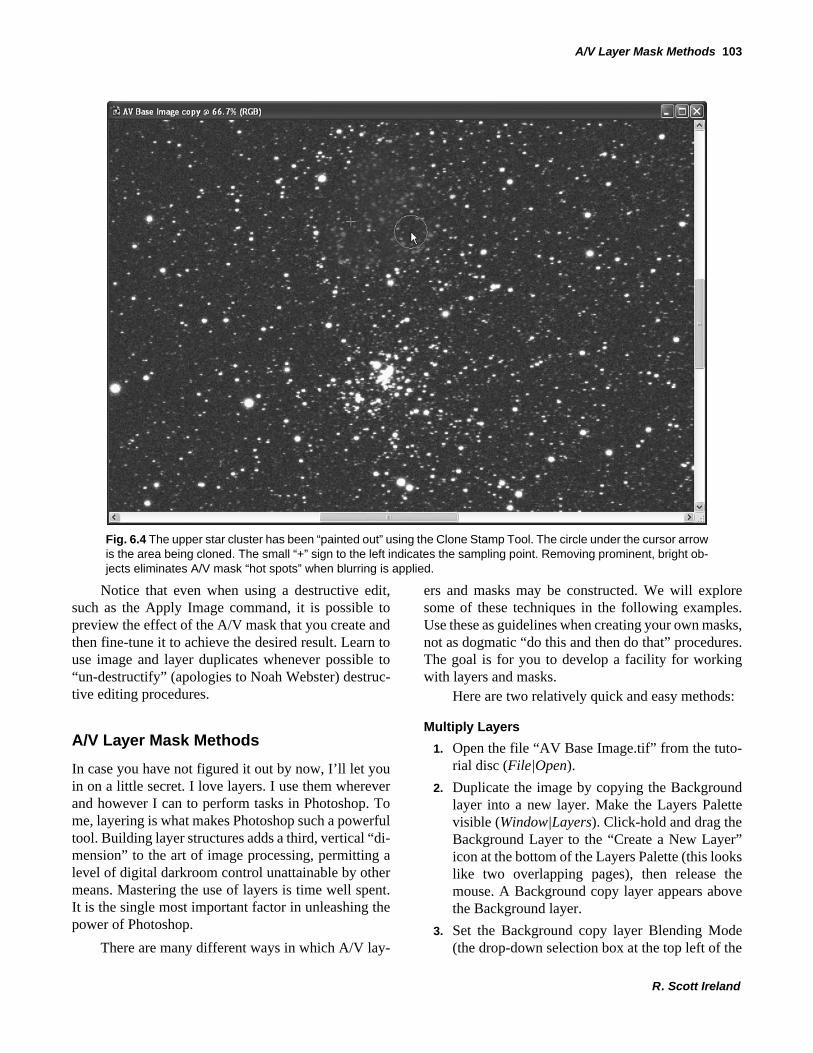
8. When you are satisfied that the clusters have beensatisfactorily eliminated (see Figure 6.4 — thecluster on top has been eliminated), once againopen the Gaussian Blur filter (Filter|Blur|Gauss-
ian Blur). Set the Radius to 90 pixels and clickOK. This is now your A/V mask.
9. Make the AV Base Image.tif window active (clickonce on it). Select Image|Apply Image, set theSource to AV Base Image copy, Layer to Back-ground, Channel to RGB and Blending to Sub-tract. Leave Opacity at 100%, Scale at 1 andchange the Offset to 50. Leave the Invert andMask boxes unchecked. Do not click OK just yet.Click the Preview check box on and off to see theeffect on the image. The vignetting disappears al-most magically! Notice that the star colors remaintrue to the original. There is only one small prob-lem. One area of the image is still too bright. Itruns along the bottom edge from the left corner toabout the center of the image. The A/V maskneeds to be tweaked a little more.
10. Click Cancel to close the Apply Image dialog boxwithout subtracting the mask. Now switch to themask window. The area along the bottom left istoo dark, so you will once again use your new-found cloning skills to lighten it up a bit.
11. Fit the A/V mask window to the screen (double-click on the Hand Tool icon — the little whiteglove — in the Toolbox), select the Clone StampTool and use a soft brush of around 250 pixels.Notice that the area above the dark line is a con-sistent neutral gray color. Use this area to cloneout the dark line and replace it with gray.
12. Make AV Base Image.tif active and once againopen the Apply Image dialog (Image|Apply Im-age). Use the settings indicated in step 9. Click thePreview box on and off to see how well you didwith your additional cloning efforts. If you are sat-isfied with the result, click OK to subtract the A/V mask from the original image. I have included afile on the tutorial disc called “AV SubtractionMask.tif”. This is my version of the A/V mask,prepared exactly as described above, that you maytry for comparison purposes.
Feel free to try the alternate Blending Modes andmask settings available in the Apply Image and Calcula-tions dialog boxes. While it is my preference to use Sub-tract and fine-tune the A/V mask directly, you may findthat other settings work better for a particular image. Trythe “Difference” or “Exclusion” Blending Modes, andexperiment with additional masking using the “Mask”check box. Try “Invert” to invert the mask too.
Fig. 6.3 The Tool Options Bar is used to select a brush sizeand style for the Clone Stamp Tool. Brush sizes may also bechanged “on the fly” from the keyboard using the left and rightbracket keys, a very handy shortcut that you will use often.
A/V Layer Mask Methods 103
R. Scott Ireland
Notice that even when using a destructive edit,such as the Apply Image command, it is possible topreview the effect of the A/V mask that you create andthen fine-tune it to achieve the desired result. Learn touse image and layer duplicates whenever possible to“un-destructify” (apologies to Noah Webster) destruc-tive editing procedures.
A/V Layer Mask Methods
In case you have not figured it out by now, I’ll let youin on a little secret. I love layers. I use them whereverand however I can to perform tasks in Photoshop. Tome, layering is what makes Photoshop such a powerfultool. Building layer structures adds a third, vertical “di-mension” to the art of image processing, permitting alevel of digital darkroom control unattainable by othermeans. Mastering the use of layers is time well spent.It is the single most important factor in unleashing thepower of Photoshop.
There are many different ways in which A/V lay-
ers and masks may be constructed. We will exploresome of these techniques in the following examples.Use these as guidelines when creating your own masks,not as dogmatic “do this and then do that” procedures.The goal is for you to develop a facility for workingwith layers and masks.
Here are two relatively quick and easy methods:
Multiply Layers
1. Open the file “AV Base Image.tif” from the tuto-rial disc (File|Open).
2. Duplicate the image by copying the Backgroundlayer into a new layer. Make the Layers Palettevisible (Window|Layers). Click-hold and drag theBackground Layer to the “Create a New Layer”icon at the bottom of the Layers Palette (this lookslike two overlapping pages), then release themouse. A Background copy layer appears abovethe Background layer.
3. Set the Background copy layer Blending Mode(the drop-down selection box at the top left of the
Fig. 6.4 The upper star cluster has been “painted out” using the Clone Stamp Tool. The circle under the cursor arrowis the area being cloned. The small “+” sign to the left indicates the sampling point. Removing prominent, bright ob-jects eliminates A/V mask “hot spots” when blurring is applied.