chapter 6 enhancement of power quality using upqc...
TRANSCRIPT

CHAPTER 6
ENHANCEMENT OF POWER QUALITY USING
UPQC
6.1. INTRODUCTION
The Unified Power Quality Conditioner is a custom power device
that incorporates the series and shunt active filters, connected back-
to-back on the dc side and allotment a common DC capacitor, it
utilizes two voltage source inverters (VSIs) that are connected to a
common DC energy storage capacitor [62]. One of these two VSIs is
coupled in series with the feeder and the other one is connected in
parallel to the same feeder. The series element of the UPQC is
accountable for mitigation of the supply side disturbances such as
voltage sags/swells, flicker, voltage unbalance and harmonics. It
inserts voltages so as to maintain the load voltages at a desired level
balanced and distortions free [121]. The simulation part analyzes the
dynamic and steady-state performance of UPQC with two typical case
studies.
In case one CSI based UPQC using PI Controller and Fuzzy
Logic Controller and in case two UPQC by synchronous reference
frame theory with PI Controller and Fuzzy Logic Controller have been
simulated and the results of voltage and current waveforms are
analyzed and presented in this chapter.

109
6.2. POWER CIRCUIT STRUCTURE
The Unified Power Quality Conditioner is a combination of series
and parallel active power filters connected back-to-back to a common
dc energy storage capacitor, as mentioned earlier. One form of UPQC
configuration [98], which is used in three-phase three wire systems, is
shown in Fig. 6.1.
Fig. 6.1 Detailed Power circuit structure for a Three-Phase UPQC.
For power factor improvement and compensation of load current
harmonics and unbalances the shunt active filter is accountable. Also,
the DC storage capacitor maintains constant average voltage across it.
The shunt part of the UPQC consists of a VSI connected to the
common DC storage capacitor on the dc side and on the ac side it is
connected in parallel with the load through the shunt interface

110
inductor and shunt coupling transformer. The shunt interface
inductor and shunt filter capacitor are used to filter out the switching
frequency harmonics produced by the shunt VSI [78]. To match the
network and VSI voltages the shunt coupling transformer is used.
6.3. PRINCIPLE OF OPERATION
In order to recognize its compensation objectives, reactive and
harmonic components of the load currents are cancelled and the load
current unbalance is eliminated due to shunt active filter injects
currents at the point of common coupling, This current injection is
offered by the dc storage capacitor and the shunt VSI. The control
system generates the appropriate switching signals for the shunt VSI
switches based on measured currents and voltages [76, 48].
The specific currents and voltages to be measured depend on
the applied control method. The shunt VSI is controlled in current
control mode. The suitable VSI switches are turned on and off at
definite time instances such that the currents injected by the shunt
active filter track some reference currents within a fixed hysteresis
band (assuming a hysteresis controller is used) according to the
compensation points. The VSI switches alternately join the dc
capacitor to the system, either in the positive or negative sense. When
the dc capacitor voltage is connected in the positive sense, it is added
to the supply voltage and the VSI current is increasing [69].
In the case of the dc capacitor connected in the negative sense,
its voltage is in opposition to the supply voltage and the VSI current is

111
decreasing. Hence alternately increasing and decreasing the current
within the hysteresis band, the reference current is tracked. This
control procedure is called “hysteresis band control” [33]. The dc side
capacitor assists two main purposes, it maintains the dc voltage with
a small ripple in the steady state and it assists as an energy storage
element to supply the real power during the transient period. The
average voltage across the dc capacitor is maintained constant and in
order that the shunt active filter can draw a leading current, this
voltage has to be higher then the peak of the supply voltage. This is
achieved through an suitable PI control, by regulating the quantity of
active current drawn by the shunt active filter from the system [50].
The series active filter is accountable for voltage compensation
during supply side disturbances, such as voltage sag/swell, flicker
and unbalance. The series part of the UPQC also consists of a VSI
connected on the dc side to the same energy storage capacitor and on
the ac side it is connected in series with the line, through the series
low pass filter (LPF) and coupling transformers [63]. The series LPF
prevents the switching frequency harmonics produced by the series
VSI entering the system. The series coupling transformers offer voltage
matching and isolation between the network and the VSI. The series
active filter compensation objectives are achieved by injecting voltages
in series with the supply voltages such that the load voltages are
balanced and undistorted. Their magnitudes are maintained at the
desired level. This voltage injection is supplied by the dc storage
capacitor and the series VSI. Based on measured supply and/or load

112
voltages the control system generates the suitable switching pulses for
the series VSI switches. The series VSI is controlled in voltage-control
mode using the well-known pulse-width-modulated (PWM) switching
technique described in detail in [44].
In order to construct the injected voltage of desired magnitude,
waveform, phase shift and frequency, the desired signal is calculated
with a triangular waveform signal of higher frequency and suitable
switching signals are generated. The dc capacitor is alternately
connected to the inverter outputs with positive and negative polarity.
The output voltages of the series VSI do not have the shape of the
desired signals, but contain switching harmonics, which are filtered
out by the series low pass filter. The amplitude, phase shift, frequency
and harmonic content of injected voltages are controllable.
6.4. POWER CIRCUIT DESIGN CONSIDERATIONS
The design of UPQC power circuit includes the selection of the
following three main parameters.
1 Shunt interface inductors.
2 DC Link reference voltage.
3 DC Link capacitor.
Design schemes on selection of the above three parameters are
presented in [62]. The design of the shunt interface inductor and the
dc reference voltage is based on the following principles. Limiting the
high frequency components of the injected currents, the
instantaneous di/dt generated by the shunt active filter should be
113
greater than the di/dt of the harmonic component of the load, so that
the proper harmonic cancellation can occur.
On one hand, for a enhanced harmonic cancellation and
reactive power compensation a higher inductance is desirable, but on
the other hand, too high inductance will consequence in slow dynamic
response of the shunt compensator and it could not be conceivable to
compensate for some of the load harmonics [2]. Hence a compromise
solution has to be found. A higher DC Link reference voltage results in
a higher di/dt of the shunt compensator, improved dynamic response
and reactive power compensation performance, but it also increases
the strain experienced by the inverter switching devices.
The dc capacitor dimension is selected to control the dc voltage
ripple within realistic limits. The dc voltage ripple is determined by
both the quantity of reactive power to be compensated and the active
power supplied by dc capacitor during the transient. To accurate for
the effects of supply voltage distortion, the series compensator is
required to inject suitable harmonic voltages [107].
6.5. CONTROL STRATEGIES
6.5.1. Control of the Shunt Active Filter
The success of an active power filter depends basically on the
design characteristics of the current controller, the technique
implemented to produce the reference model and the modulation
procedure used. The control process of a shunt active power filter
must estimate the current reference waveform for each phase of the

114
inverter, preserve the dc voltage constant, and produce the inverter
gating signals [119]. Also the compensation effectiveness of an active
power filter depends on its aptitude to follow the reference signal
calculated to compensate the distorted load current with a minimum
error and time delay.
The shunt component of UPQC can be controlled in two ways
6.5.1.1. Tracking the Shunt Converter Reference Current
The load current is sensed and the shunt compensator
reference current is calculated from it. The reference current is
determined by calculating the active fundamental component of the
load current and subtracting it from the load current. This control
technique involves both the shunt active filter and load current
measurements.
6.5.1.2. Tracking the Supply Current
In this case the shunt active filter guarantees that the supply
reference current is tracked. Thus, the supply reference current is
analyzed rather than the current injected by the shunt active filter.
The supply current is often required to be sinusoidal and in phase
with the supply voltage. Since the waveform and phase of the supply
current is known, only its amplitude needs to be determined. Also,
when used with a hysteresis current controller, this control technique
involves only the supply current measurement.

115
6.5.1.2.1. Average DC Voltage Regulation
This method is used for supply reference current determination
and it is based on the fact that the magnitude of the supply current
depends on power balance between the supply and the load. The dc
capacitor serves as energy storage element. If the shunt active filter
losses are neglected, in steady-state, the power supplied by the system
has to be equal to the real power demand of the load and no real
power flows into the dc capacitor [98].
The average dc capacitor voltage is thus maintained at reference
voltage level. If a power unbalance caused by a load change occurs,
the dc capacitor must supply the power difference between the supply
and load that will result in reducing the dc capacitor voltage. To
reestablish the average dc capacitor voltage to the reference level some
active power has to be supplied to the dc capacitor, so the magnitude
of the supply current has to be increased.
When the average dc capacitor voltage increases, the magnitude
of the supply current has to be decreased. So, by controlling the
average voltage across the dc capacitor the amplitude of the supply
current is spontaneously controlled. Applying this concept, the control
circuit can by simplify and the number of current sensors reduced.
Therefore, this control technique has been chosen to be used in the
UPQC simulation model (presented in section 6.4). This method is
discussed in detail in [48, 49]. The dc voltage regulation is achieved by
using a PI Controller and Fuzzy Logic Controller. Fuzzy Logic
Controller gives fast response than PI Controller. The capacitor voltage

116
is compared with some reference value and a PI Controller processes
the voltage error then this error and change of error are inputs of
Fuzzy Logic Controller.
6.5.1.2.2. Instantaneous PQ Theory
The idea of instantaneous active and reactive powers and its
application for shunt active filter reference currents generation was
created by Akagi et al. in [53]. The instantaneous active and reactive
powers for a three-phase three-wire system are described as
i
i
vv
vv
q
p (6.1)
Where the three-phase voltages are modified from a-b-c to
frame and vice versa using the following transformation relations:
c
b
a
v
v
v
v
v
23230
21211
3
2
(6.2)
v
v
v
v
v
c
b
a
2321
2321
01
3
2 (6.3)
The same modification matrices are used for the conversion of
currents. Then from (6.3) the currents i and i are expressed:
q
p
vv
vv
vvi
i
22
1 (6.4)
Both active power p and reactive power q defined above are
constituted of two components, constant (or dc) and oscillating.

117
ppp ~ qqq ~ (6.5)
where p and q are the standard active and reactive powers (dc
values) creating from the symmetrical fundamental (positive sequence)
component of the load current p the standard active power delivered
to the load and q is the average reactive power drawn by the load. To
get better the power factor, q has to be completely )1(cos or
moderately )1(cos compensated by the shunt active filter.
Fig. 6.2 Controlling circuit of Shunt Active Filter.
p~ and q~ are the ripple active and reactive powers (ac values) from the
harmonic and asymmetrical fundamental (negative sequence)
components of the load currents. These two oscillating components
are equal to zero if both the load currents and supply voltages are
symmetrical and undistorted. In many cases the supply voltage
irregularity and distortion are so small that they can be neglected. So,
the supply voltages are assumed to be proportioned sinusoids. Then,

118
if the load currents are regular and undistorted, p~ =0 and q~ =0. When
the load currents are either asymmetrical or imprecise p~ and q~ are
different from zero and they have to be compensated by the shunt
active filter.
In the case where the shunt active filter is to compensate for
making the supply currents balanced, precise and in phase with the
supply voltages, the shunt active filter reference currents in the
reference frame will be calculated as per (6.6).
p
vv
vv
vvi
i
f
f
~
~1
22*
,
*
,
(6.6)
The oscillating element p~ is achieved by filtering out the
constant element p from the total active power P, using a high pass
filter. The appearance similar to (6.3) is used to transform the
currents from to a-b-c reference frame. For the regulation of the
DC capacitor voltage, the active power loss compensate component
pLoss has to be added to p~ in (6.6) [68].
The instantaneous p-q theory and its purpose for reference
currents calculation is conversed in detail in [3] and many supporting
examples are presented. It is to be stated that, when using this
approach a PLL is not needed. The above-described method for
reference currents withdrawal only works when the supply voltages
are equilibrium and harmonic free, as it was assumed above.

119
6.5.1.2.3. Synchronous Reference Frame Theory
In this case the load currents presented in the frame are
converted into a synchronous reference frame as per (6.7). [34]
i
i
wtwt
wtwt
i
i
q
d
)cos()sin(
)sin()cos( (6.7)
The reference frame is synchronized with the supply voltage,
and is rotating with the equal frequency. A PLL is needed for
implementing this method.
Like p and q in the instantaneous p-q method presented above,
id and iq are also composed of dc and ac components according to
(6.8).
ddd iii~
qqq iii~
(6.8)
The dc components di and qi correspond to the fundamental
load currents and the ac components di~
and qi~
correspond to the load
currents harmonics. Component qi corresponds to the reactive power
drawn by the load. The separation of the ac component can be
achieved by filtering out the dc offset. The compensation reference
signals are obtained from the following expressions.
drefd ii~
,
qqrefq iii~
, (6.9)

120
The shunt active filter reference currents in a-b-c frame are
obtained with the following expression.
refq
refd
cf
bf
af
i
i
wtwt
wtwt
i
i
i
,
,
*
,
*
,
*
,
)cos()sin(
)sin()cos(
2321
2321
01
3
2
(6.10)
This method does not include the source voltages in
calculations and the reference currents are derived directly from the
load currents. So, it could seem that the calculation of reference
currents using this approach is not affected by voltage unbalance
or/and distortion. However, as it was mentioned above a PLL is used
with this technique. And the transformation angle is obtained from
the supply voltage. Hence the presentation of this approach is also
influenced by the unbalance and distortion in supply voltages. A
relative analysis of this issue and above discussed control techniques
under unbalanced and distorted supply voltages is presented in [126].
6.5.2. Control of the DC Bus
For a voltage source inverter the dc voltage needs to be
preserved at a certain level to make sure the dc-ac power transfer. For
a current source inverter the dc current needs to be preserved at a
certain level to make sure the dc-ac power transfer. Because of the
switching and other power losses inside UPQC, the voltage level of the
dc capacitor will be reduced if it is not compensated. Thus, the DC
Link voltage control unit is intended to keep the average dc bus

121
voltage constant and equal to a given reference value. The DC Link
voltage control is achieved by adjusting the small amount of real
power absorbed by the shunt inverter. This small amount of real
power is regulated by changing the amplitude of the fundamental
component of the reference current. The ac source offers some active
current to recharge the dc capacitor [129].
Thus, in addition to reactive and harmonic components, the
reference current of the shunt active filter has to have some amount of
active current as compensating current. This active compensating
current flowing through the shunt active filter regulates the dc
capacitor voltage. The DC Link inductor functions as dc power supply
sources and hence does not demand any external power source.
However, in order to maintain constant dc current in the energy
storage element, a small fundamental current is drawn to compensate
active filter losses.
Fig. 6.3 Block diagram of DC Link Voltage PI Controller.
Usually a PI Controller is used for determining the magnitude of
this compensating current from the error between the average voltage
across the dc capacitor and the reference voltage. In [122] a practical

122
approach (Ziegler-Nichols tuning rules) for tuning the PI Controller is
proposed. The PI Controller has a simple structure and fast response.
As an alternative to PI Controller, a simple linear control
technique is proposed in [23] with application to a single-phase shunt
active filter. This is a proportional gain type control and the
proportional coefficient is calculated instantaneously as a function of
the dc capacitor average voltage error.
Here, the expression used for calculation of the proportional
coefficient is obtained through integration of a fist-order differential
equation. However, the formula derivation for the proportional
coefficient is not that simple for a three-phase UPQC, if possible at all
(a high-order differential equation has to be integrated analytically).
Also, a residual steady-state error occurs with a proportional only
controller.
The general structure of a complete fuzzy control system is
given in Fig. 6.4. The plant control ‘Du’ is inferred from the two state
variables, error (i) and change in error (Δi).
Fig. 6.4. Basic structure of fuzzy control system

123
The actual crisp input are approximates to the closer values of
the respective universes of is course. Hence, the fuzzyfied inputs are
described by singleton fuzzy sets. The elaboration of this controller is
based on the phase plan. Here NB is negative big, NM is negative
medium, ZR is zero, PM is positive medium and PB is positive big, are
labels of fuzzy sets
Table 6.1 Rules Base for current control
Table 6.1 shows one of possible control rule base. The rows
represent the rate of the error change e and the columns represent the
error i. Each pair (i, Δi) determines the output level NB to PB
corresponding to u.
The continuity of input membership functions, reasoning method,
and defuzzification method for the continuity of the mapping ufuzzy(i, Δi)
is necessary. The triangular membership function, the max-min
reasoning method, and the center of gravity defuzzification method are
used.
In [98], instead of the PI Controller, Fuzzy Logic Controller is
proposed for processing the dc capacitor average voltage error. The

124
Fuzzy Logic Controller has advantages over the PI Controller. It does
not require an accurate mathematical model can work with imprecise
inputs, it can handle non-linear functions and it is more robust. As
per the simulation results presented in following sections show that
the Fuzzy Logic Controller have a better dynamic behavior than the PI
Controller.
6.5.3. Control of the Series Active Filter
The series component of UPQC is controlled to insert the proper
voltage between the point of common coupling and load, such that the
load voltages become balanced, distortion free and have the desired
magnitude. Theoretically the injected voltages can be of any arbitrary
magnitude and angle. However, the power flow and device rating are
significant issues that have to be considered when determining the
magnitude and the angle of the injected voltage.
While the shunt compensator VA rating is reduced as the active
power consumption of the series compensator is minimized and it also
compensates for a part of the load reactive power demand. Also the
shunt compensator must provide the active power injected by the
series compensator. Thus, in this case the VA rating of the shunt
compensator increases, an analysis for optimization of the converter
rating is presented in [48,49] and an approximate sub optimal control
strategy for UPQC minimum losses operation is proposed.

125
Fig. 6.5 Series Active Filter Control Block.
The load voltage lV is equal to the sum of the voltage at the point
of common coupling tV and the voltage injected by the series filter fV :
)( jbaVVV ftl (6.12)
where a + jb is a vector of unity magnitude and 900 ahead the
supply current.
If the load voltage is assumed to be 00 ll VV the following
quadratic equation is obtained from (6.12).
02222
tlflf VVVVaV (6.13)
Solving this quadratic equation the magnitude of the injected
voltage reference is obtained. As it was mentioned above, the phase of
the injected voltage reference is 900 from the supply current. The
quadratic equation (6.13) gives two solutions, from which the solution
corresponding to a smaller voltage injection has to be chosen. The
fundamental of the instantaneous injected voltage is obtained by
multiplying fV determined from (6.13) with the sinusoidal template
phase locked to the supply current. To compensate for supply voltage

126
unbalance and distortion some additional component has to be added
to the reference calculated above, which can be determined by
subtracting the positive sequence fundamental component from the
voltage at the PCC [50].
An alternative strategy for the determination of the UPQC-Q
injected voltage reference, based on instantaneous symmetrical
components, is proposed in [51]. The instantaneous power in a three-
phase system is defined as (6.14).
ccbbaa ivivivP (6.14)
The instantaneous symmetrical components for ai , bi and ci are
defined as (6.15).
c
b
a
a
a
a
a
i
i
i
aa
aaa
i
i
i
i2
2
2
1
0
012
1
1
111
3
1 (6.15)
Where
0120jea and the subscripts 0, 1 and 2 correspond to
zero, positive and negative sequence respectively. For balanced
currents the component 0ai is equal to zero and the component 1ai is
complex conjugate of 2ai . The same transformation is applied for
voltages.
Taking into consideration (6.15) and above comments, equation
(6.14) can be rewritten as (6.16).
)Re(2 *
11
*
111
*
1211200 aaaaaaaaaaaa ivivivivivivp (6.16)

127
Since the desired load voltages are balanced sinusoids and the
currents flowing through the series compensator are also balanced
(shunt compensator action), the instantaneous UPQC output power
outP is constant and this must be equal to the average power entering
the UPQC (losses are neglected) avinP , . Thus from (6.16) we get (6.17).
avinalisalvlasalasalout pivivP ,,,1,1,
*
1,1, cos2Re2 (6.17)
Where 1,avl and 1,ais are the angles of the vectors 1,alv and
1,asi , respectively. From 6.17
1,
1
1,1,
,
,2
cos ais
asal
avin
alvliv
p
(6.18)
The desired instantaneous symmetrical components of the load
voltage are defined and given in (6.19).
1,
1,
0
2
3
2
1
0
avl
avl
j
m
j
m
la
la
la
eV
eV
v
v
v
(6.19)
Then the instantaneous load voltages are calculated by applying
a transformation inverse to (6.15). Once the instantaneous load
voltages are obtained, the reference series filter voltages are obtained
using the following expression (6.20).
tlf vvv (6.20)

128
6.6. SIMULATION OF UPQC WITH PI CONTROLLER AND
FUZZY LOGIC CONTROLLER
UPQC is a complex power electronics device and the analysis of
its behavior, which leads to improved understanding, would be very
difficult without computer simulations (if possible at all). The overall
design process can be shortened through the use of computer
simulations, since it is usually easier to study the influence of a
parameter on the system behavior in simulation. A UPQC simulation
models has been created in Matlab/Simulink, then dynamic and
steady-state performance of UPQC are analyzed for two typical case
studies. The results of voltage and current waveforms are presented
below.
Fig. 6.6 Main system without UPQC.
Fig. 6.7 Three Phase Voltage Source Subsystem.

129
6.6.1. Current Source Inverter (CSI) based UPQC using PI
Controller and Fuzzy Logic Controller
In this work unified power quality conditioner is being used as a
unified active power conditioning device to mitigate both current as
well as voltage harmonics at a distribution end of power system
network. The performance of UPQC mainly depends upon its fast
operation and accuracy of compensation signals is derived.
Fig. 6.8 Main system with UPQC.

130
Fig. 6.9 Series Active Filter/Shunt Active Filter Subsystem.
Fig. 6.10 Shunt Active Filter with PI Controller Sub system.
The steady state and dynamic operation of control circuit in
different load current and utility voltages conditions is studied
through simulation results. The presented method has acceptable
dynamic response with a very simple configuration of control circuit.

131
Fig. 6.11 Series Active Filter Controller Subsystem.
Fig. 6.12 Non Linear Load Subsystem.
This work presents performance validation of current source
inverter based UPQC using Fuzzy Logic Controller and its results are
compared with current source inverter based UPQC using
conventional PI Controller. Fuzzy Logic Controller used system THD
values and waveforms are better than PI Controller used system.

132
Fig. 6.13 Shunt Active Filter with Fuzzy Logic Controller Subsystem.
Fig. 6.14 Fuzzy Logic Controller Subsystem.

133
The FLC based compensation scheme eliminates voltage and
current magnitude of harmonics with good dynamic response. UPQC
and its converters and their controllers simulink design structures are
shown Fig. 6.8 to Fig. 6.14. Extensive simulation results using RL
load connected through an uncontrolled bridge rectifier validates the
performance of FLC compensator. CSI based UPQC has a faster phase
voltage control loop and inherent short circuit protection capability. It
also minimizes the cost as in this case passive filter connection
between UPQC and the load is not necessary. The only disadvantage
of CSI based UPQC is that its DC Link inductor is bulky and heavy
which leads to high DC Link losses.
Table 6.2 Simulation parameters for test case 1 with UPQC
For the verification of the performance of UPQC the system is
simulated. Simulation parameters mentioned in the following table
6.2. To observe the performance of shunt filter for voltage correction,
the shunt filter is switched on first and then the series filter is
switched on.
Supply 3Ф, 50Hz,230V RMS, with 10% of 5th & 5% of 7th harmonics
Load (150+j12.56)Ω
DC Link inductance 150mH
DC Link resistance 0.01Ω
LC filter 25μF, 1Ω,0.4mH
Sample time 1μs
Smoothening inductor 1mH
Line inductance 50μH
Line resistance 0.01Ω

134
Table 6.3 Comparison of Total Harmonic Distortion.
The large data of source current, reference load voltage, power
loss component and reference compensation current from
conventional method are collected at a sample rate of 0.05 sec. These
data are used for Fuzzy Logic Controller. The performance of UPQC
using designed based on PI Controller and Fuzzy Logic Controller for a
non linear load derived using an uncontrolled diode bridge with Total
Harmonic Distortion is presented in the table 6.3.
Fig. 6.15 Three Phase Source Current (UPQC with PI Controller).
S.No Parameter UPQC with PI
Controller
UPQC with fuzzy
logic Controller
1 THD for Load Current 29.29% 28.14%
2 THD for Source Current 5.34% 0.76%
3 THD for Source Voltage 0.34% 0.33%
4 THD for Load Voltage 5.16% 1.16%

135
Fig. 6.16 Source Current in Phase A (UPQC with PI Controller).
Fig. 6.17 Compensation Current in Phase A (UPQC with PI Controller).
Fig. 6.18 Compensation Voltage (UPQC with PI Controller).
Fig. 6.19 Load Voltage and Current (UPQC with PI Controller).

136
Fig. 6.20 Source Voltage in Phase A (UPQC with PI Controller).
Fig. 6.21 Three Phase Source Voltage (UPQC with PI Controller).
Fig. 6.22 Three Phase Load Current (UPQC with PI Controller).

137
Fig. 6.23 Load Current in Phase A (UPQC with PI Controller).
Fig. 6.24 Injected Voltages (UPQC with PI Controller).
Fig. 6.25 DC Link Current (UPQC with PI Controller).
Fig. 6.26 Load Voltage in Phase A (UPQC with PI Controller).

138
Fig. 6.27 Injected Voltage (UPQC with FL Controller).
Fig. 6.28 Load Voltage (UPQC with FL Controller).
Fig. 6.29 Load Voltage and Current (UPQC with FL Controller).
Fig. 6.30 Three Phase Source Voltage (UPQC with FL Controller).
139
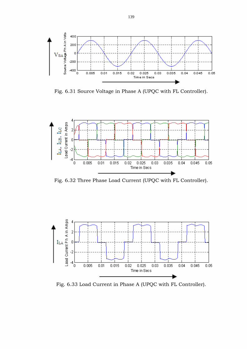
Fig. 6.31 Source Voltage in Phase A (UPQC with FL Controller).
Fig. 6.32 Three Phase Load Current (UPQC with FL Controller).
Fig. 6.33 Load Current in Phase A (UPQC with FL Controller).

140
Fig. 6.34 Source Current in Phase A (UPQC with FL Controller).
Fig. 6.35 Three Phase Source Current (UPQC with FL Controller).
Fig. 6.36 Compensation Current (UPQC with FL Controller).

141
Fig. 6.37 Compensation Current in Phase A (UPQC with FL
Controller).
Fig. 6.38 Compensation Voltage (UPQC with FL Controller).
Fig. 6.39 DC Link Current (UPQC with FL Controller).
From Fig. 6.15 to Fig. 6.26 show the performance
characteristics of UPQC with PI Controller. From Fig. 6.27 to Fig. 6.39
show the performance characteristics of UPQC with Fuzzy Logic
Controller. It is observed that the UPQC with Fuzzy Logic controller
system performs satisfactorily comparing with PI Controller
performance. The shunt active filter compensates voltage harmonics

142
and reactive power. Similarly the series filter compensates for voltage
harmonics present in the system, harmonic content of source voltage
eliminates. The performance of shunt active filter and series active
filter for voltage harmonics, current harmonics and reactive power
compensation is high in UPQC with Fuzzy logic Controller.
The Fuzzy Logic Controller performs better in elimination of
THD of source current and regulation of DC Link current. This can be
observed from its performance characteristics of source voltage as
shown in Fig. 6.21 for UPQC with PI Controller and Fig. 6.30 for UPQC
with Fuzzy Logic Controller. The system voltages even have distortions
and unbalances, provided the sinusoidal and balanced source
currents from efficient control strategy of shunt active filter. The
harmonics and unbalanced voltages are cancelled by series-active
power filter.
UPQC performance mainly depends upon how accurately and
quickly reference signals are derived. By using conventional Akagi’s
principle reference signals is derived. The simulated result shows that
it has considerable response time for yielding effective compensation
in the network. Using conventional compensator data, a Fuzzy Logic
Controller is tuned with large number of data points. Simulation
results clearly demonstrate the victorious application of Fuzzy Logic
Controller for the success of UPQC for RL load using uncontrolled
rectifier.
The simulation results have shown that the UPQC perform
better with FLC. Proposed scheme eliminates both voltage as well as

143
current harmonics effectively. It is also observed that the response
time for derivation of compensation signals reduces significantly with
improved accuracy.
6.6.2. UPQC by Synchronous Reference Frame Theory
with PI Controller and Fuzzy Logic Controller
Nonlinear apparatus, such as power electronics converters,
introduce harmonic currents in the AC system and amplify overall
reactive power demanded by the equivalent load. Also, the number of
sensitive loads that require ideal sinusoidal supply voltages for their
appropriate operation has increased. In order to keep power quality
under limits proposed by standards, it is necessary to include some
sort of compensation.
Fig. 6.40 UPQC with Synchronous Reference Frame Theory.
144
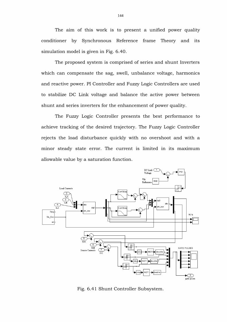
The aim of this work is to present a unified power quality
conditioner by Synchronous Reference frame Theory and its
simulation model is given in Fig. 6.40.
The proposed system is comprised of series and shunt Inverters
which can compensate the sag, swell, unbalance voltage, harmonics
and reactive power. PI Controller and Fuzzy Logic Controllers are used
to stabilize DC Link voltage and balance the active power between
shunt and series inverters for the enhancement of power quality.
The Fuzzy Logic Controller presents the best performance to
achieve tracking of the desired trajectory. The Fuzzy Logic Controller
rejects the load disturbance quickly with no overshoot and with a
minor steady state error. The current is limited in its maximum
allowable value by a saturation function.
Fig. 6.41 Shunt Controller Subsystem.

145
Fig. 6.42 Series Controller Subsystem.
Fig. 6.43 Shunt Active Filter with Fuzzy Logic Controller Subsystem.

146
Table 6.4 Simulink Parameters for test case 2 with UPQC
Fig. 6.44 Source Current in Phase-A (UPQC with PI Controller).
Fig. 6.45 Source voltage in Phase-A (UPQC with PI Controller).
Parameters Values
Source Phase voltage 220v/50Hz
DC Link Voltage 600v
Shunt inverter rating 15kVA
Series inverter rating 15kVA
Shunt inverter inductance(Lf) 3mH
Shunt inverter Capacitance (Cf) 10µF
Switching Frequency 20kHz
Series inverter inductance(Ls) 3mH
Series inverter Capacitance (Cs) 15µF
Series inverter Resistance (Rs) 12Ω

147
Fig. 6.46 Three Phase Source voltage (UPQC with PI Controller).
Fig. 6.47 Three Phase Source currents (UPQC with PI Controller).
Fig. 6.48 Three Phase Load Voltage (UPQC with PI Controller).
Fig. 6.49 Compensated Voltage (UPQC with PI Controller).

148
Fig. 6.50 Compensated Current in Phase-A (UPQC with PI Controller).
Fig. 6.51 Injected Voltage in Phase-A (UPQC with PI Controller).
Fig. 6.52 Injected Current in Phase-A (UPQC with PI Controller).
Fig. 6.53 DC Link Voltage (UPQC with PI Controller).

149
Fig. 6.54 Load Voltage and Current (Power Factor) (UPQC with PI
Controller).
Fig. 6.55 Load Current in Phase A (UPQC with PI Controller).
Fig. 6.56 Source Current in Phase A (UPQC with FL Controller).
Fig. 6.57 Source Voltage in Phase A (UPQC with FL Controller).

150
Fig. 6.58 Three Phase Source Voltage (UPQC with FL Controller).
Fig. 6.59 Three Phase Source Current (UPQC with FL Controller).
Fig. 6.60 Compensated Voltages (UPQC with FL Controller).
Fig. 6.61 Three Phase Load Current (UPQC with FL Controller).

151
Fig. 6.62 Load Current in Phase A (UPQC with FL Controller).
Fig. 6.63 Compensated Current in Phase A (UPQC with FL Controller).
Fig. 6.64 Voltage Injection in Phase A (UPQC with FL Controller).
Fig. 6.65 Current Injection in Phase A (UPQC with FL Controller).

152
Fig. 6.66 DC Link Voltage (UPQC with FL Controller).
Fig. 6.67 Load Voltage and Current (Power Factor) (UPQC with FL
Controller).
In order to validate the control strategies are discussed above,
digital simulation studies are made the system uncomplicated. The
UPQC system is designed and simulated with PI Controller and Fuzzy
Logic Controller based on synchronous reference frame theory.
Simulated circuits are given in Fig. 6.40 to Fig. 6.43. The control
presents the best performances, to achieve tracking of the desired
trajectory. The Fuzzy Logic Controller rejects the load disturbance
rapidly with no overshoot and with a negligible steady state error. The
current is limited in its maximal admissible value by a saturation
function. The reason for superior performance of fuzzy controlled
153
system and the controller is able to realize different control law for
each input state (Error and Change in Error).
In this work, power circuit is modeled as a 3-phase 3-wire
system with a non linear load comprised of RC load which is connected
to source through three phase diode bridge. Simulation parameters
used in simulation are shown in table 6.4. The non linear load is a
parallel RC and diode rectifier bridge. It imposes a non sinusoidal
current to source. Non linear load current is shown in Fig. 6.55 and
Fig. 6.62 while providing PI Controller and Fuzzy Logic Controller for
UPQC Respectively.
The developed UPQC system has been tested for harmonic
elimination and reactive power compensation. Simulation results
shown in Fig. 6.44 and Fig. 6.56 source current wave forms are plotted.
In Fig. 6.52 and Fig. 6.65 Plotted injected current wave forms. In Fig.
6.50 and Fig. 6.63 plotted compensated current wave forms. Shunt
inverter is activated in 0.02 sec of operation. Immediately the source
current is corrected. The source current wave forms are shown in Fig.
6.45 and Fig. 6.57. Fig. 6.51 and Fig. 6.64 shown the voltage injected
by the series inverter. The shunt part has been able to correct the
source current appropriately. To eliminate swell and sag of the voltage,
voltage distortions imposed to load from the source are properly
compensated by series inverter. In this simulation, series inverter
operates at 0.02 sec and voltage source faces voltage sag with 100V. A
voltage swell with 50 V occurs in 0.08 sec. Simulation results show

154
that the load voltage is constant during the operation of UPQC series
inverter.
By using PI and Fuzzy Logic Controllers individually for shunt
controller DC Link voltage is shown in Fig. 6.53 and Fig. 6.64
respectively. From that the distortions in DC Link voltage can be
minimized by Fuzzy Logic Controller. In this simulation, series and shunt
inverters start to operate at 0.02 sec. As it is seen, capacitor voltage is
decreasing until this moment. By operating shunt inverter, the
capacitor voltage increases and reaches to the reference value (600 V).
At 0.04 sec of operation voltage sag amplitude for 100 V occurs in
source voltage.
Fig. 6.53 and Fig. 6.66 respectively have shown the exact operation
of control loop of DC link capacitor voltage, while providing PI
Controller and Fuzzy Logic Controller for UPQC. RL load with 6 kW
active power and 6 kVAR reactive power is applied in simulation to study
how reactive power is compensated by shunt inverter. Simulation
results show that the phase difference between voltage and current is
cleared by shunt inverter operation. Actually, by operating UPQC,
required reactive power is provided.
Fig. 6.54 and Fig. 6.67 shown the load current and load voltage
with PI Controller and Fuzzy Logic Controller with UPQC circuit
simulated individually. It is shown that, load current leads voltage
initially. At 0.06 sec of operation and operating shunt inverter the
phase difference between voltage and current gets zero. Comparison of

155
this study results with related studies, indicates that the proposed
system compensates voltage and current distortions accurately and the
response time of the control system is relatively low and also the
proposed control system is simply applicable.
In this work Unified Power Quality Conditioner is analyzed and
simulated through synchronous reference frame theory with PI
Controller and Fuzzy Logic Controller. Simulation results show the
proposed system's ability in voltage distortion, reactive power and
current harmonics compensation. Fuzzy Logic Controller balances the
power between series and shunt inverters by stabilizing DC Link
voltage.
6.7. SUMMARY
The series component of the UPQC is responsible for mitigation
of the supply side disturbances viz. voltage sags/swells, flicker,
voltage unbalance and harmonics. It inserts voltages so as to
maintain the load voltages at a desired level, balanced and distortion
free.
Detailed power circuit structure, Principle of operation, Power
circuit design considerations, Control strategies for shunt active filter
like Tracking the shunt converter reference current, Tracking the
supply current in this average dc voltage regulation, Instantaneous p-
q theory, Synchronous Reference Frame Theory, for Control of the dc
bus, through PI Controller, Fuzzy Logic Control and Control of the
series active filter and finally in simulation study part analyze the

156
dynamic and steady-state performance of UPQC with two typical case
studies.
In test Case I CSI based UPQC using PI Controller and Fuzzy
Logic Controller, the simulation results have shown that the UPQC
perform better with FLC proposed scheme eliminates both voltage as
well as current harmonics effectively. It is also observed that the
response time for derivation of compensation signals reduces
significantly with improved accuracy.
And in test Case II UPQC by Synchronous Reference frame
Theory with PI Controller and Fuzzy Logic Controller have been
simulated. Simulation results show the proposed system's ability in
voltage distortion, reactive power and current harmonics compensation.
Fuzzy logic controller balances the power between series and shunt
inverters by stabilizing DC Link voltage and the results of voltage and
current waveforms are presented in this chapter.