chapter 6 external memory disk and raid (redundant arrays of independent disks) cs-147 fall 2010...
TRANSCRIPT

Chapter 6
External Memory
Disk and RAID (Redundant Arrays of Independent Disks)
CS-147 Fall 2010
Jonathan Wang

Magnetic Disk Coated with magnetizable material for read
and write purpose. The substrat used to be aluminum. Recently use glass.
Better stiffness Greater shock/damage resistance Lower fly height Improved uniformity of surface helps to
reduced read-write errors

Magnetic Write and Read Mechanism
Head: Fixed head
One read-write head per track
Heads build into a fixed ridged arm
Movable head
One read-write head per surface
Build into a movable armWhen the track passes under the head, it generates a current of the same polarity as the one already recorded.
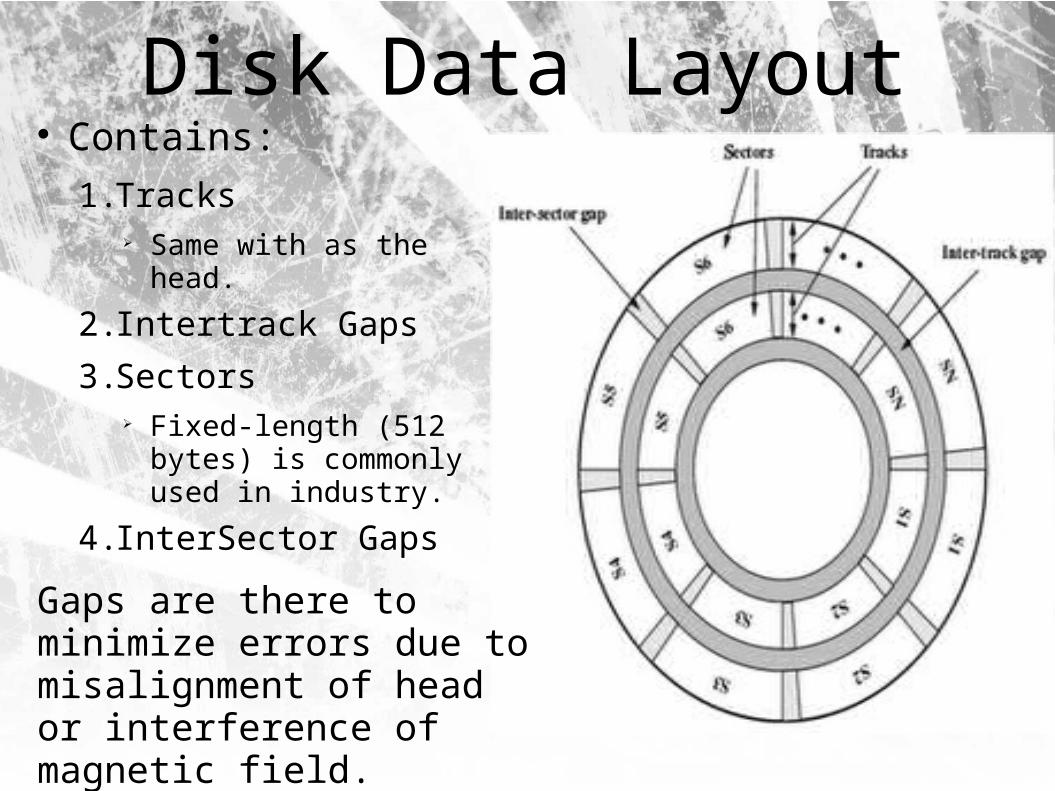
Disk Data Layout Contains:
1. Tracks Same with as the head.
2. Intertrack Gaps
3. Sectors Fixed-length (512 bytes)
is commonly used in industry.
4. InterSector Gaps
Gaps are there to minimize errors due to misalignment of head or interference of magnetic field.

Disk Layout Methods CAV – Constant Angular Velocity Multiple Zone Recording: to enhance density(capacity)

Characteristics Movable Head or not Removability
Provides unlimited storage capacity
Easy data transfer between systems
Multiple Platter Single or double sided.

Disk Performance Parameters
Seek Time : time to position the head at the track Rotational Delay : The time it takes for the begining of the
sector to reach the head Transfer Time : time required for the transfer
T = Transfer time
b = Number of bytes to be transfered
N = Number of bytes on a track
r = rotation speed in rev/sec
Units usually is in ms, and considered average case
T=b /rN

RAID Stand for Redundant Arrays of Independent Disks
RAID is a set of physical disk drives viewed by the perating system as a single logical drive
Data are distributed across the physical drives of array in ascheme known as striping, describes subseuently.
Redundant disk capacity is used to store parity information, which quarantees data recoverability in case of a disk failure.
Uses Array Management Software Level 0 ~ 6 and more, such as RAID 10 (a combination of
RAID 0 and RAID 1)

RAID Level 0 Not a true member of RAID family No redundancy or fault tolerance High transfer capacity for large
and small I/O data It's there because it distrbites
datas across mutiple disks No parity coculation is needed Easy to implement

RAID Level 0In a transaction environment, there may be hundreds of
I/O requests per second. A disk array can provide high I/O executtion rates by balancing the I/O load across mutiple disks.
Parallel processing
Any error is uncorrectable
One disk's failure will result in all data in an array being lost

RAID Level 1Redundancy is achieved by having a mirror disk
Insufficient use of space
Read request is really efficiency (the one involves minimum seek time plus rotational latency)
Write request could be done parallelly (T = the larger one)
Recovery is really simple.Just replace the broken diskwith a new one

RAID
Comparison – see Table 6.4 p.204

Reference
Text Book - Computer Organization and Architecture: Designing for Performance, 8th Edition By William Stallings, Prentice Hall
Wikipedia http://en.wikipedia.org/wiki/RAID