chapter 6a - eastern mediterranean university
TRANSCRIPT

CIVL222 STRENGTH OF MATERIALS
Chapter 6aTORSION
Instructor: Assoc.Prof.Dr. Mürüde Çelikağ

Definition
Torque is a moment that tends totwist a member about itslongitudinal axis. Slender memberssubjected to a twisting load are saidto be in torsion.
CIVL222Dr. Mürüde Çelikağ2

Example of TorsionWhen opening the lid of a common plastic drinks bottle, atorque T applied to the cap is gradually increased until the plasticconnectors between the cap and the bottle experience shear failure.
CIVL222Dr. Mürüde Çelikağ3

Example of TorsionShafts are structural members with length significantly greater
than the largest cross-sectional dimension used in transmitting
torque from one plane to another.
CIVL222Dr. Mürüde Çelikağ4

Example of Torsion
CIVL222Dr. Mürüde Çelikağ5

Example of TorsionFor a non-circular section member or an opensection member subjected to torsion:
Plane cross sections of the member do notremain plane and the cross sections distort in amanner which is called warping. In otherwords, the fibers in the longitudinal directiondeform unequally.
CIVL222Dr. Mürüde Çelikağ6

Example of Torsion
CIVL222Dr. Mürüde Çelikağ7

Example of TorsionFor a circular shaft or a closed circular sectionmember subjected to torsion:
Plane circular cross sections remain plane andthe cross sections at the ends of the memberremain flat.
The length and the radius of the memberremain unchanged.
Plane circular cross sections remainperpendicular to the longitudinal axis.
CIVL222Dr. Mürüde Çelikağ8

Analogy Between Axial Deformation and Torsion
• Axial Force (P)• Elongation ()• Normal Stress ()• Extensional Strain ()• Modulus of Elasticity (E)
• Torque (T)• Twist Angle ()• Shear Stress ()• Shear Strain ()• Shear Modulus (G)
CIVL222Dr. Mürüde Çelikağ9

Torsion Theory for circular sections
CIVL222Dr. Mürüde Çelikağ10

Absence of Warping
CIVL222Dr. Mürüde Çelikağ11

Investigate Deformation
CIVL222Dr. Mürüde Çelikağ12

Investigate Deformation
CIVL222Dr. Mürüde Çelikağ13

State of Pure Shear
CIVL222Dr. Mürüde Çelikağ14

Shear Strain Relate to Angel of Twist
CIVL222Dr. Mürüde Çelikağ15

Linear Variation of Shear Stress
CIVL222Dr. Mürüde Çelikağ16

Linear Variation of Shear Stress
CIVL222Dr. Mürüde Çelikağ17

Shear Stress Surfaces
CIVL222Dr. Mürüde Çelikağ18

Shear Stress Surfaces
CIVL222Dr. Mürüde Çelikağ19

Moment “dM” developed on “dA”
CIVL222Dr. Mürüde Çelikağ20

Setup the Integration “dM” over the Area “A”
CIVL222Dr. Mürüde Çelikağ21

Relating Torque and Stress
CIVL222Dr. Mürüde Çelikağ22
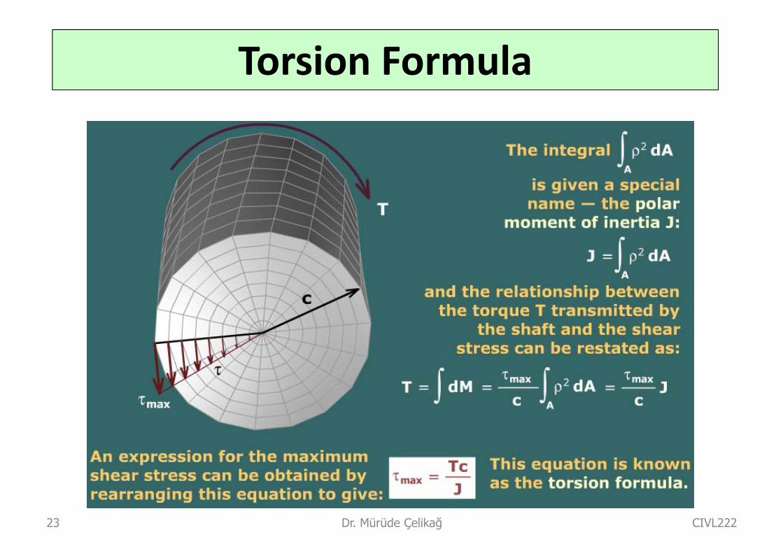
Torsion Formula
CIVL222Dr. Mürüde Çelikağ23

“J” for Solid Circular Shape
CIVL222Dr. Mürüde Çelikağ24

“J” for Hollow Circular Shape
CIVL222Dr. Mürüde Çelikağ25

Angle of Twist Formula
CIVL222Dr. Mürüde Çelikağ26

Summery of Key Equations
CIVL222Dr. Mürüde Çelikağ27

Sign Conventions
CIVL222Dr. Mürüde Çelikağ28

Sign Conventions
CIVL222Dr. Mürüde Çelikağ29

Sign Conventions
CIVL222Dr. Mürüde Çelikağ30

Sign Conventions
CIVL222Dr. Mürüde Çelikağ31

Example #1
CIVL222Dr. Mürüde Çelikağ32
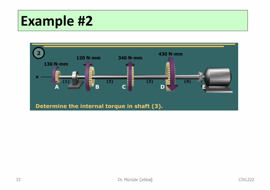
Example #2
CIVL222Dr. Mürüde Çelikağ33

Example #3
The steel shaft of a socket wrench has a diameter of 8.0 mm. and a length of200 mm (see figure). If the allowable stress in shear is 60 MPa, what is themaximum permissible torque Tmax that may be exerted with the wrench?Through which angle (in degrees) will the shaft twist under the action of themaximum torque? (Assume G = 78 GPa and disregard any bending of theshaft.)
CIVL222Dr. Mürüde Çelikağ34

Example #4
A hollow steel shaft used in a constructionauger has outer diameter d2 =150 mm. andinner diameter d1 = 115 mm. (see figure).The steel has shear modulus of elasticity G= 80 GPaFor an applied torque of 17 kN.m,determine the following quantities:
(a) shear stress 2 at the outer surface ofthe shaft,
(b) shear stress 1 at the inner surface,and
(c) rate of twist (degrees per unit oflength).
Also, draw a diagram showing how theshear stresses vary in magnitude along aradial line in the cross section.
CIVL222Dr. Mürüde Çelikağ35

Example #5A hollow aluminum tube used in a roof structure has an outside diameter d2 =100 mmand an inside diameter d1 =80 mm (see figure). The tube is 2.5 m long, and thealuminum has shear modulus G= 28 GPa.(a) If the tube is twisted in pure torsion by torques acting at the ends, what is the angle
of twist (in degrees) when the maximum shear stress is 50 MPa?(b) What diameter d is required for a solid shaft (see figure) to resist the same torque
with the same maximum stress?(c) What is the ratio of the weight of the hollow tube to the weight of the solid shaft?
CIVL222Dr. Mürüde Çelikağ36

Example #6Four gears are attached to a circular shaft and transmit the torques shown inthe figure. The allowable shear stress in the shaft is 68 MPa.
(a) What is the required diameter d of the shaft if it has a solid cross section?
(a) What is the required outside diameter d if the shaft is hollow with an insidediameter of 25 mm ?
CIVL222Dr. Mürüde Çelikağ37
Work Done and Power Transmitted
When a force moves in a straight line with constant velocity the work
done is given by the product of the magnitude of the force and the
distance through which it has moved.
Work done = force × distance
The power transmitted by this action is defined as the rate at
which this work is done, i.e. the work done in unit time.
CIVL222Dr. Mürüde Çelikağ38

Work Done and Power TransmittedThe ‘distance’ travelled by a rotating body is measured by the
number of radians through which it rotates. The work done by a
torque acting on a shaft is therefore given by the product of the
magnitude of the Torque and the amount of rotation in radians.
For one revolutions of the shaft:
The work done = T ×2
(since the shaft turns through 2 radians in one revolution)
If the shaft is rotating at N revolutions per minute, then
work done = T ×2 N
(units of work per minute)
CIVL222Dr. Mürüde Çelikağ39

Work Done and Power TransmittedUsually the torque will be measured in Newton meters (N‐m) and
therefore the units of work will also be N.m. However, it is more
usual to give work in joules (J) which are equal numerically to
Newton meters.
1 joule = 1 Newton meter
Power is measured in watts (W),
1 W = 1 J/s
= 1 N.m/s
=(1/60) N.m/minCIVL222Dr. Mürüde Çelikağ40

Work Done and Power Transmitted
Hence, the power transmitted by a shaft rotating at N revolutionsper minute and subject to torque of T (N.m) will be given by:
WattsNTPower602
: the shaft’s angular velocity (rad/s) : the frequency of shaft’s rotation (Hz = 1 revolution/s)
rpm : revolutions per minutehp: horsepower , 1 hp = 746 W
fPPT
fTTP
2
2
f 2
CIVL222Dr. Mürüde Çelikağ41

Example #7
A motor drives a shaft at 12 Hz and delivers 20 kW of power (see figure).
(a) If the shaft has a diameter of 30 mm, what is the maximum shear stressmax in the shaft?
(b) If the maximum allowable shear stress is 40 MPa, what is the minimumpermissible diameter dminof the shaft?
CIVL222Dr. Mürüde Çelikağ42

Example #8The drive shaft for a truck (outer diameter 60 mm and inner diameter 40 mm) isrunning at 2500 rpm (see figure).
(a) If the shaft transmits 150 kW, what is the maximum shear stress in theshaft?
(b) If the allowable shear stress is 30 MPa, what is the maximum power thatcan be transmitted?
CIVL222Dr. Mürüde Çelikağ43