chapter 6:peer to peer protocols - dr. bhargavi goswami can be added to the blocks before...
TRANSCRIPT

Chapter 6:Peer to Peer
ProtocolsDr. Bhargavi Goswami
Associate Professor – Head
Department of Computer Science
Garden City College – Bangalore.
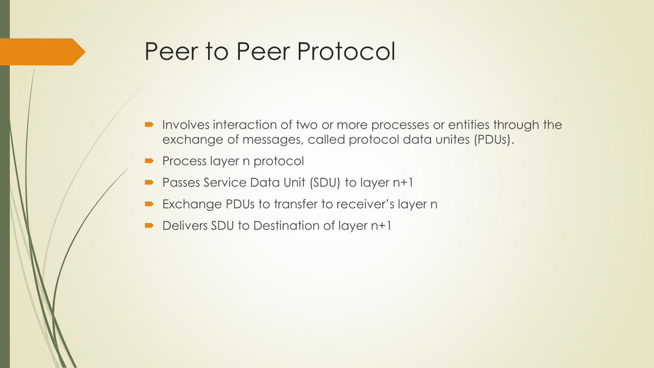
Peer to Peer Protocol
Involves interaction of two or more processes or entities through the
exchange of messages, called protocol data unites (PDUs).
Process layer n protocol
Passes Service Data Unit (SDU) to layer n+1
Exchange PDUs to transfer to receiver’s layer n
Delivers SDU to Destination of layer n+1
Service Models
Constant Bit Rate
Variable non real time Bit Rate
Variable real time Bit Rate
Best Effort Service
Quality of Service (QoS)

Features of Services
Arbitrary Message Size or structure
Sequencing
Reliability
Timing
Pacing
Flow Control
Multiplexing
Privacy, Integrity and Authentication

Basic Settings of Peer to Peer Protocol
HOP BY HOP
Initiates error recovery quickly
More reliable service
Node processing is complex
Every element should process
correctly.
Impose small delay
Frame arrive in order
Not recommended in Noisy
Unreliable channel
END TO END
Uses network layer services
Recommended for environment
with less errors
Intermediate nodes are free from
responsibility of error recovery
Blocks of information are
forwarded across the path
Error recovery is performed only
by end systems

ARQ
Automatic Repeat Request Protocols
Does error control
Provide reliable data transfer
Is a control mechanism for data transfer
Based on Acknowledgement and Non Acknowledgement
i.e ACK and NACK
Elements
Protocol
Frames (Data and Control)
Timeout Mechanism
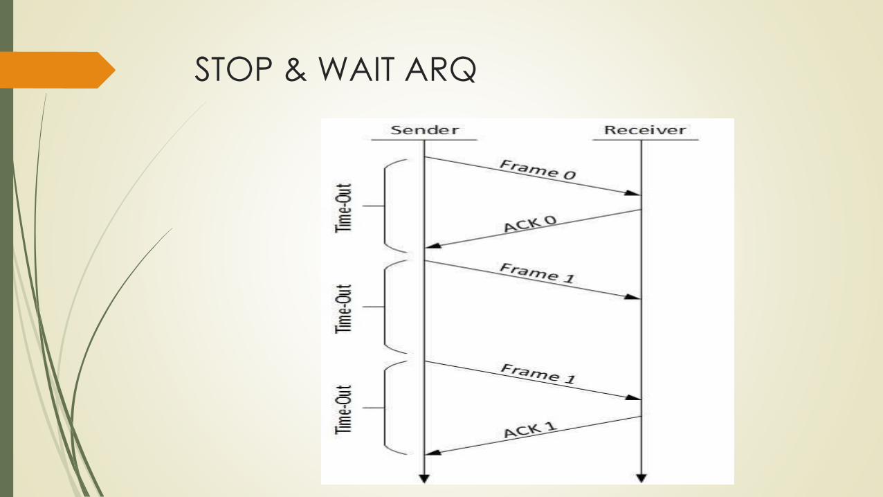
STOP & WAIT ARQ

Stop & Wait
The sender maintains a timeout counter.
When a frame is sent, the sender starts the timeout counter.
If acknowledgement of frame comes in time, the sender transmits the next
frame in queue.
If acknowledgement does not come in time, the sender assumes that
either the frame or its acknowledgement is lost in transit. Sender retransmits
the frame and starts the timeout counter.
If a negative acknowledgement is received, the sender retransmits the
frame.

Frame Lost

Delayed ACK Frame

Requirement of
ACK Number

Solution:
ACK Number

Piggybacking

Same Piggybacking

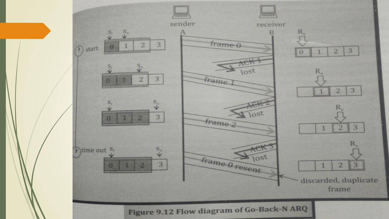
Go Back N
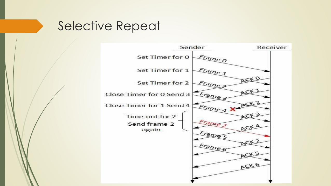
Selective Repeat


Sliding Window
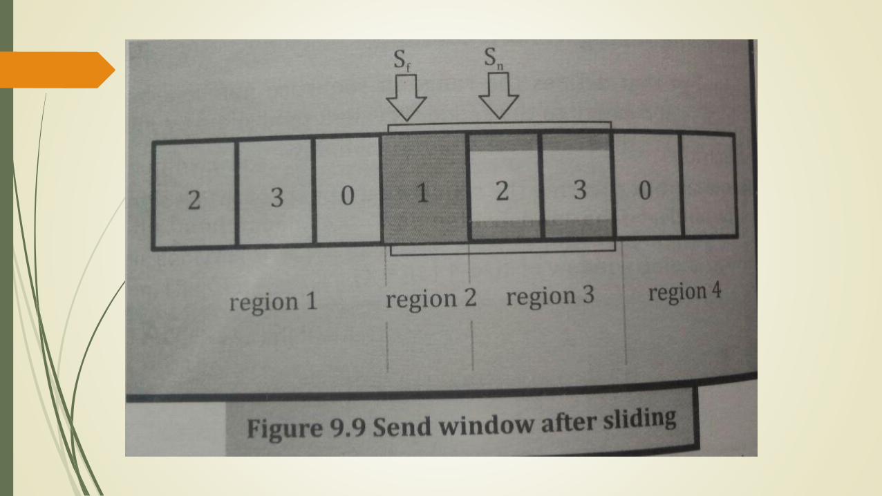


Sliding Window Flow Control

Sliding Window Flow Control
It guarantees the reliable delivery of data
It ensures that data delivers in order
It enforce flow control between sender and receiver
Two types
On – Off Flow Control
Sliding Window Flow Control

TIMING RECOVERY FONR
SYNCHRONOUS SERVICES
The information must be input to decoder at the same rate at which it was produced at encoder.
But, in reality, network impose delay.
This effect is called Timing Jitter.
Solution: Timing Recovery protocols.
Timestamp can be added to the blocks before transmission begins.
These timestamps are used by receivers for further time synchronization.
Clock Recovery Procedure: Procedure to synchronize the receiver clock to transmitter clock.
Two techniques:
Adaptive Clock Recovery
Clock Recovery with Synchronous Network

Adaptive Clock Recovery

Clock Recovery with Synchronous N/w
All the elements are synchronized to common clock
Use GPS – Global Positioning System
Fn = (1/M)Fs (1/N)
Fr = Fn - ∆F
Fs – Frequency of sender
Fn – Frequency of network
N – Cycles of Sender
M – Cycles of Network
∆F – Difference of frequency, Delta Frequency
Fr – Received Frequency
Fn – Network Frequency
FRAMING
Two Types:
Character Based / Byte Stuffing
Flag Based / Bit Stuffing
Practice examples taught on board.
Check next two figures.

Byte Stuffing

Bit Stuffing

Point to Point Protocol (PPP)
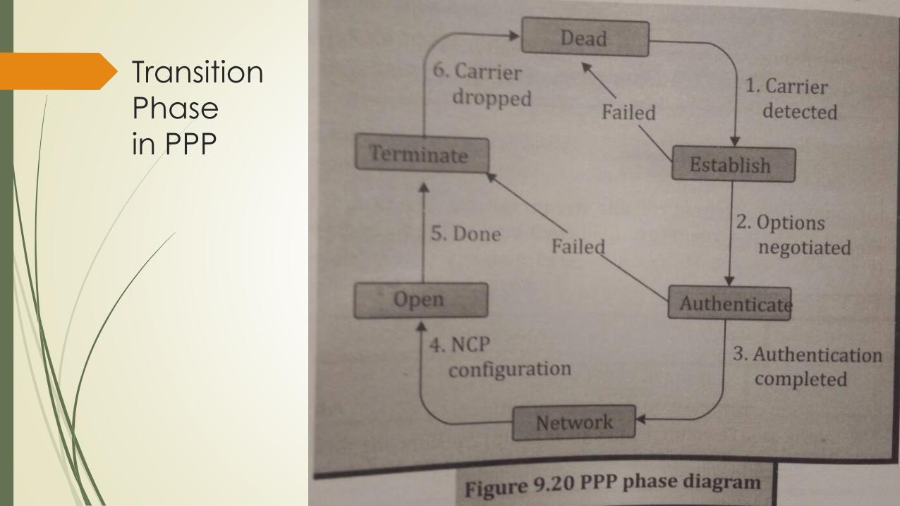
Transition
Phase
in PPP
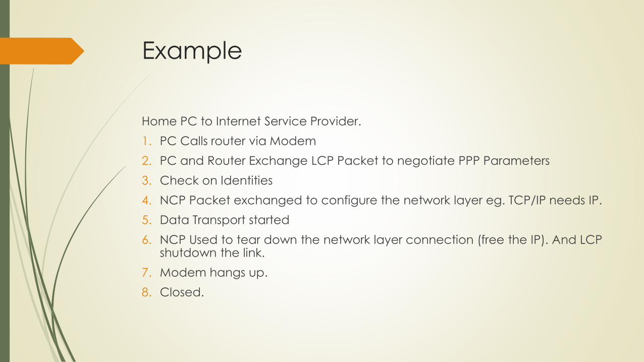
Example
Home PC to Internet Service Provider.
1. PC Calls router via Modem
2. PC and Router Exchange LCP Packet to negotiate PPP Parameters
3. Check on Identities
4. NCP Packet exchanged to configure the network layer eg. TCP/IP needs IP.
5. Data Transport started
6. NCP Used to tear down the network layer connection (free the IP). And LCP shutdown the link.
7. Modem hangs up.
8. Closed.

HDLC – High Level Data Link Control
It is Bit Oriented Protocol for communication over Point to Point and
Multipoint links.
It implement ARQ Techniques.
Topics:
Configuration and Transfer Modes
Frame Format
Frame Types
Control Field

HDLC Configuration and Transfer
Modes
Provides two modes
NRM – Normal Response Mode
ABM – Asynchronous Balanced Mode
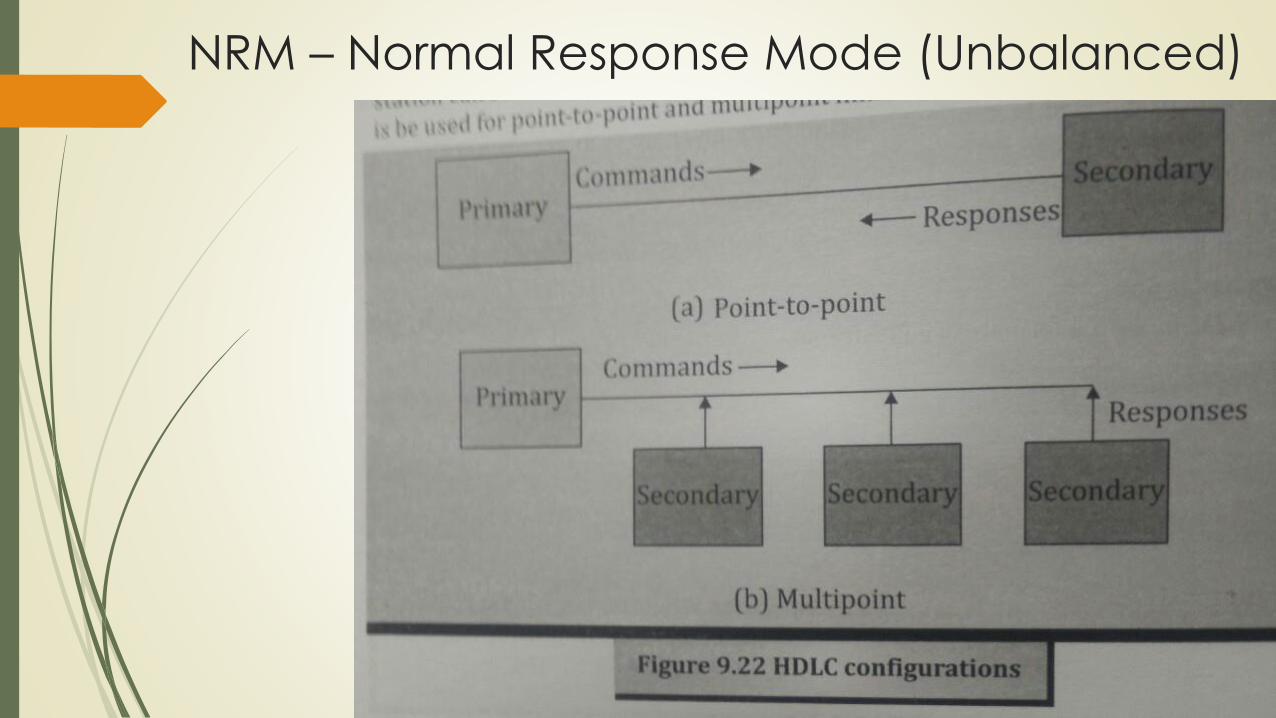
NRM – Normal Response Mode (Unbalanced)

ABM – Asynchronous Balanced Mode
(Balanced)

HDLC Frame Format

HDLC Frame Types
INFORMATION FRAME: Used to transport data and control information
relating to user data.
SUPERVISORY FRAME: Used only to transport control information
UNNUMBERED FRAME: Reserved for system management. Eg. For
Connection Establishment and Termination.
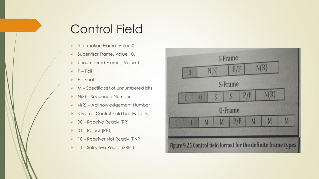
Control Field Information Frame. Value 0
Supervisor Frame. Value 10.
Unnumbered Frames. Value 11.
P – Poll
F – Final
M – Specific set of unnumbered bits
N(S) – Sequence Number
N(R) – Acknowledgement Number
S-Frame Control Field has two bits:
00 – Receive Ready (RR)
01 – Reject (REJ)
10 – Receiver Not Ready (RNR)
11 – Selective Reject (SREJ)

STATISTICAL MULTIPLEXING
A type of Communication Link Sharing
Here, a communication channel is divided into an arbitrary number of
variable bit rate digital channels or data streams.
Adaptive to instantaneous traffic demands.
Alternative of TDM and FDM.
Provides improved link utilization, called statistical multiplexing gain.
Facilitated through packet mode.
Each stream is divided into packets that are delivered asynchronously in
FCFS – First Come First Served fashion.
Some scheduling techniques like fair queuing or differentiated QoS.

STATISTICAL MULTIPLEXING
Supports wireless schemes:
Random Frequency Hopping Orthogonal Frequency Division Multiple Access (RFH-OFDMA)
Code Division Multiple Access (CDMA).
Normally imply “On Demand” service rather than “Pre-allocated resources”.
Here, each packet contains complete destination address information.
Examples:
Digital TV Transmission. Channel#=Program ID. Has Constant Length.
UDP and TCP Protocols. Channel#=Port#. Variable Length.
X.25 and Frame Relay. Channel#=Virtual Connection ID (VCI). Varying Length. Packet Switched Network.
ATM – Asynchronous Transfer Mode. Fixed Length. VCI and VPI – Virtual Path Identifier.

Comparison
Statistical Multiplexing
Fixed (Time Slot) / Variable (data
frames) length.
Frames experience variable
delay.
Bandwidth divided into arbitrary
variable number of channels.
Ensures no slot wastage.
Performed over Data Link Layer.
Time Division Multiplexing
Assigned to same recurrent time
slot in every TDM Frame.
Frames experience fixed delay.
#Channels and Data Rate are
fixed.
TDM can waste slots.
Performed over Physical Layer.

THANK YOU.UNIT 3 OVER. TOMORROW WE WILL START WITH UNIT 4.