chapter 7 body builder... · alternator output characteristic ... 11 chapter 7 electrical system...
TRANSCRIPT
Chapter 7ELECTRICAL SYSTEM
LAMPS, REFLECTIVE DEVICES AND ••••••••••••••••••••••••••••••••••••••• 1 ASSOCIATED EQUIPMENTFUSE BLOCK, RELAY PANEL AND FUSIBLE LINK BLOCK ••••••• 4ALTERNATOR OUTPUT CHARACTERISTIC •••••••••••••••••••••••••••••• 11INSTALLATION OF 180A ALTERNATOR (OPT) •••••••••••••••••••••••••• 13ELECTRICAL POWER SOURCES •••••••••••••••••••••••••••••••••••••••••••••• 15BACK-UP BUZZER (OPTION EQUIPMENT) ••••••••••••••••••••••••••••••• 28HARNESS WIRING •••••••••••••••••••••••••••••••••••••••••••••••••••••••••••••••••••• 29
KK-US007C

1
Chapter 7 ELECTRICAL SYSTEM
KK-US007C
LAMPS, REFLECTIVE DEVICES AND ASSOCIATED EQUIPMENT
Requirements of FMVSS 108
The following devices are provided, located and/or wired by Hino Motors Sales U.S.A., Inc. Requirements of FMVSS 108. Head lamps Frontsidereflexreflectors Front side marker lamps Front turn signal lamps Front cab roof clearance & I.D. lamps Side turn signal lamps * Rearreflexreflectors(Temporaryloc.) * Taillamps(Temporaryloc.) * Stoplamps(Temporaryloc.) * Licenseplatelamps(Temporaryloc.) * Backuplamps(Temporaryloc.) * Rearturnsignallamps(Temporaryloc.)
The following additional devices must be installed on the body and meet all the requirements of FMVSS 108. Rear side marker lamps Rearsidereflexreflectors Rear clearance lamps Rearidentificationlamps
The following additional devices must be installed on the body and meet all the requirements of FMVSS 108 if the overall vehicle length is 30 feet or greater. Intermediate side marker lamps Intermediatesidereflexreflector
Installation of Rear Lamps
Asrearcombinationlamps(Taillamps,Stoplamps,TurnsignallampsandRearreflexreflec-tors,Backuplamps,Licenseplatelamps)aretemporallylocatedontheendofchassisframeat factory, they should be relocated by subsequent manufacturer to conform to FMVSS 108.
Notes for relocation of rear combination lamps:
• Tail lamps,stop lampsanddirectionsignal lamps,backup lamps, licenseplate lampsaredesigned in one body as rear combination lamps. Do not install the rear combination lamps horizontally or up side down not to affect the performance of license plate lamps and water drain holes.
• Install therearcombinationlampstotheoutsideofframeendatrightandleftusingsameholes,boltsandnutsofframeendastemporaryfitted.
• Wheninstallingtherearcombinationlampstotherearbody,besuretopreventbreakage,deflectionandvibrationofrearcombinationlampbody.
• Tighteningtorqueforrearcombinationlampmountingnutsis50±20kgf·cm(3.6±1.4lb·ft).

2
Chapter 7 ELECTRICAL SYSTEM
KK-US007C
Installation of Rear Combination Lamps

3
Chapter 7 ELECTRICAL SYSTEM
KK-US007C
• Tighteningtorqueforthestaymountingboltsis210±80kgf·cm(15±6lb·ft).
• Donotapplyrust-proofingclearlacquertolamplensorbody.
• Bracketforrearlicenseplateisfittedtogetherwithrearcombinationlamp,LH,tothechassisframe.
Case of rear combination lamp less option
Preper the rear combination lamp which complied with FMVSS 108 by the Body Manufacturer and install to comply with FMVSS 108.Vehicles are equipped with connectors linked to rear combination lamp as shown in following figure.
Cautions Regarding Additional Turn Signal Lamps
Thisistocautionyoutoavoidapossiblefailureofflasherunitarisingfromexcessiveelectricalloadingduetothemountingofadditionalturnsignallampstotheflasherunitofthevehicle.
Theflasherunitoneachvehicleisdesignedtoaccommodatethetotalwattageoftheturnsig-nal lamps, if anticipated in the design of the vehicle, when they work as hazard warning lamps, in which case the total wattage doubles that of their use as turn signals.
TheturnsignallampsoneachvehiclemeettheFMVSS(FederalMotorVehicleSafetyStan-dard:aregulationintheU.S.A.),andnoadditionallampisneededinthisregardsolongasthe vehicle is used as it was designed.
In consequence, adding the turn signal lamps is strictry prohibited due to design capacity of flasherunit.
4
Chapter 7 ELECTRICAL SYSTEM
KK-US007C
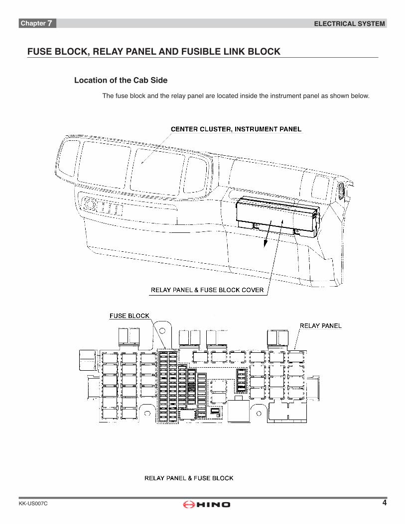
FUSE BLOCK, RELAY PANEL AND FUSIBLE LINK BLOCK
Location of the Cab Side
The fuse block and the relay panel are located inside the instrument panel as shown below.
5
Chapter 7 ELECTRICAL SYSTEM
KK-US007C
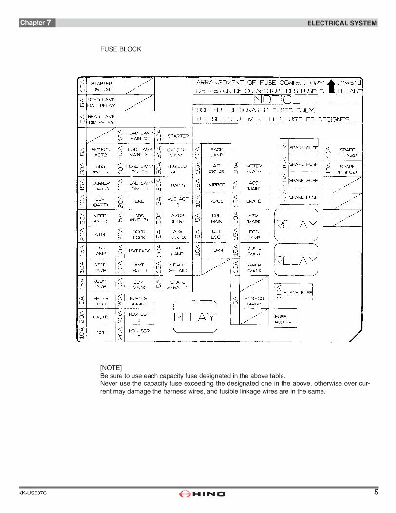
FUSE BLOCK
[NOTE]Be sure to use each capacity fuse designated in the above table.Neverusethecapacityfuseexceedingthedesignatedoneintheabove,otherwiseovercur-rent may damage the harness wires, and fusible linkage wires are in the same.
6
Chapter 7 ELECTRICAL SYSTEM
KK-US007C
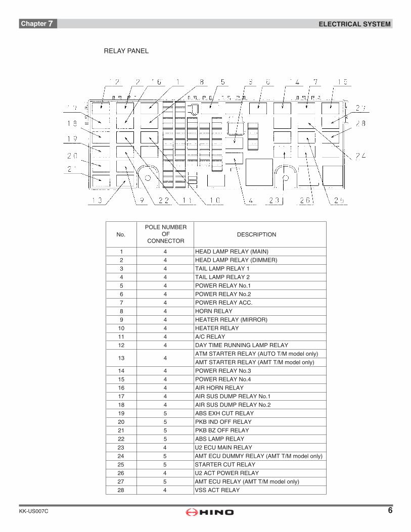
RELAY PANEL
POLE NUMBEROF
CONNECTORNo. DESCRIPTION
1 HEAD LAMP RELAY (MAIN)
2 HEAD LAMP RELAY (DIMMER)
3 TAIL LAMP RELAY 1
4 TAIL LAMP RELAY 2
5 POWER RELAY No.1
6 POWER RELAY No.2
7 POWER RELAY ACC.
8 HORN RELAY
9 HEATER RELAY (MIRROR)
10 4 HEATER RELAY
11 4 A/C RELAY
12 4 DAY TIME RUNNING LAMP RELAY
13 4ATM STARTER RELAY (AUTO T/M model only)
AMT STARTER RELAY (AMT T/M model only)
14 4 POWER RELAY No.3
15 4 POWER RELAY No.4
16 4 AIR HORN RELAY
17 4 AIR SUS DUMP RELAY No.1
18 4 AIR SUS DUMP RELAY No.2
19 5
4
4
4
4
4
4
4
4
4
ABS EXH CUT RELAY
20 5 PKB IND OFF RELAY
21 5 PKB BZ OFF RELAY
22 5 ABS LAMP RELAY
23 4 U2 ECU MAIN RELAY
24 5 AMT ECU DUMMY RELAY (AMT T/M model only)
25 5 STARTER CUT RELAY
26 4 U2 ACT POWER RELAY
27 5 AMT ECU RELAY (AMT T/M model only)
28 4 VSS ACT RELAY
7
Chapter 7 ELECTRICAL SYSTEM
KK-US007C
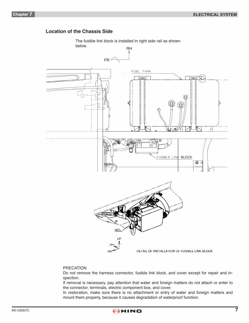
Location of the Chassis Side
The fusible link block is installed in right side rail as shown below.
FR
RH
BLOCK
PRECATIONDonotremovetheharnessconnector, fusible linkblock,andcoverexceptforrepairandin-spection.If removal is necessary, pay attention that water and foreign matters do not attach or enter to theconnector,terminals,electriccomponentbox,andcover.In restoration, make sure there is no attachment or entry of water and foreign matters and mount them properly, because it causes degradation of waterproof function.
8
Chapter 7 ELECTRICAL SYSTEM
KK-US007C
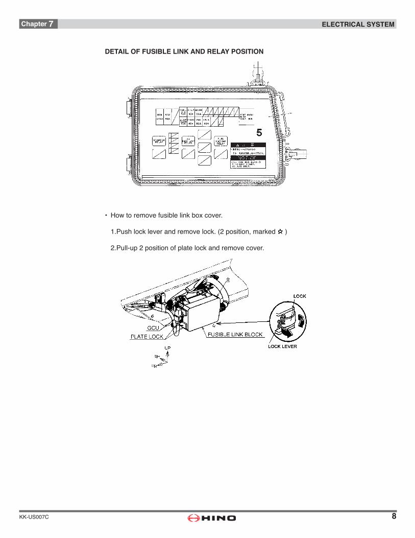
• Howtoremovefusiblelinkboxcover.
1.Pushlockleverandremovelock.(2position,marked)
2.Pull-up2positionofplatelockandremovecover.
DETAIL OF FUSIBLE LINK AND RELAY POSITION

9
Chapter 7 ELECTRICAL SYSTEM
KK-US007C
Installation of Additional Switches
Whenfittingswitchesofthebodyattheinstrumentpanelorfloorconsole,observefollowingprecautions.
• Fittheswitchofthebodyatfreespaceofinstrumentpanelorfloorconsole. (seefollowingfigure)
• Neverconnectanelectricalcircuitofthebodytotheexistingswitch,otherwiseovercurrentmay damage harness and switch.
• Fitacautionplateshowingthepurposeofeachswitchestopreventwrongoperation.
• Followingfiguresshowallswitcheswhichareinstalled.
INSTRUMENT PANEL
10
Chapter 7 ELECTRICAL SYSTEM
KK-US007C
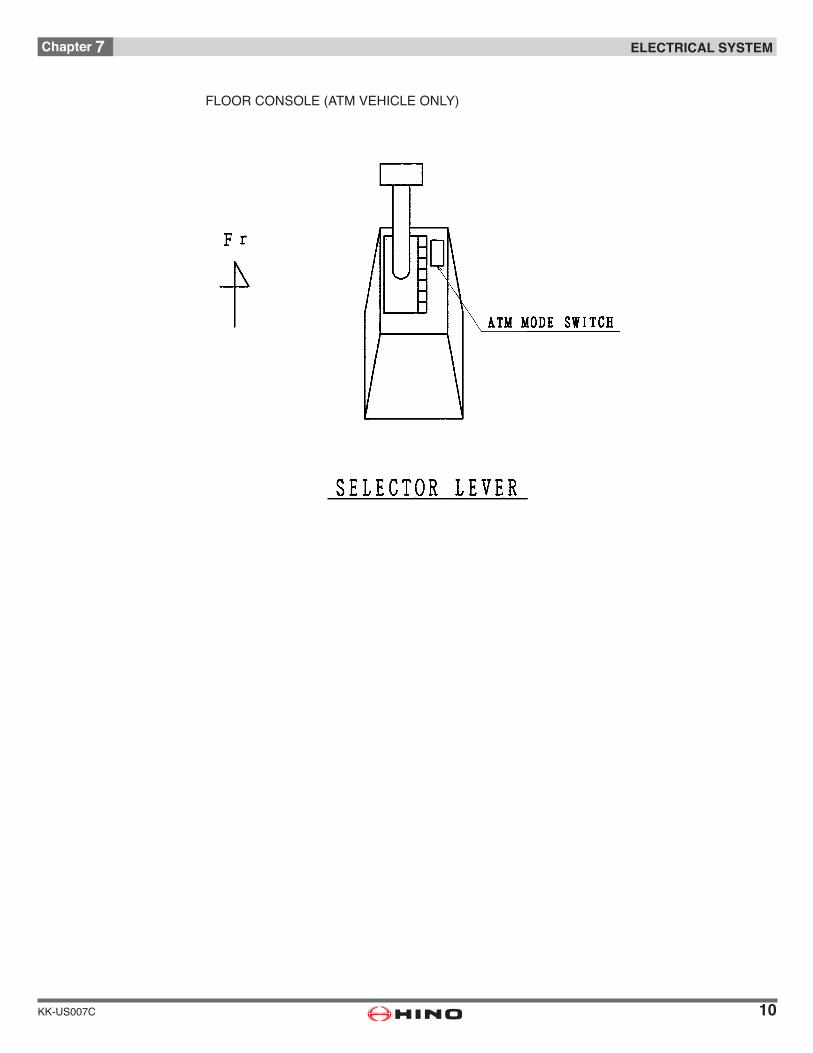
FLOORCONSOLE(ATMVEHICLEONLY)
11
Chapter 7 ELECTRICAL SYSTEM
KK-US007C
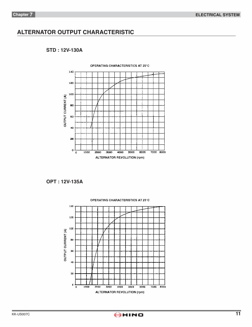
ALTERNATOR OUTPUT CHARACTERISTIC
STD : 12V-130A
OPT : 12V-135A
12
Chapter 7 ELECTRICAL SYSTEM
KK-US007C
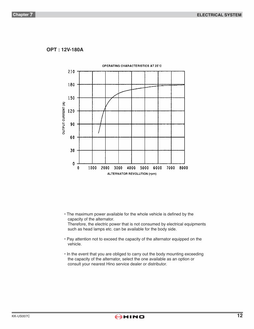
OPT : 12V-180A
•Themaximumpoweravailableforthewholevehicleisdefinedbythe capacity of the alternator. Therefore, the electric power that is not consumed by electrical equipments such as head lamps etc. can be available for the body side.
•Payattentionnottoexceedthecapacityofthealternatorequippedonthe vehicle.
•Intheeventthatyouareobligedtocarryoutthebodymountingexceeding the capacity of the alternator, select the one available as an option or consult your nearest Hino service dealer or distributor.
13
Chapter 7 ELECTRICAL SYSTEM
KK-US007C
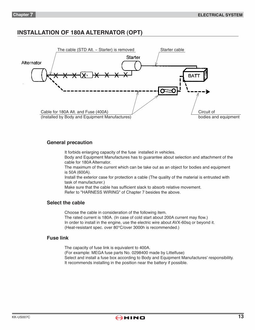
INSTALLATION OF 180A ALTERNATOR (OPT)
General precaution
It forbids enlarging capacity of the fuse installed in vehicles.Body and Equipment Manufactures has to guarantee about selection and attachment of thecable for 180A Alternator.Themaximumofthecurrentwhichcanbetakeoutasanobjectforbodiesandequipmentis50A(600A).Installtheexteriorcaseforprotectionacable(Thequalityofthematerialisentrustedwithtaskofmanufacturer.)Makesurethatthecablehassufficientslacktoabsorbrelativemovement.Referto"HARNESSWIRING"ofChapter7besidestheabove.
Select the cable
Choose the cable in consideration of the following item.Theratedcurrentis180A.(Incaseofcoldstartabout200Acurrentmayflow.)Inordertoinstallintheengine,usetheelectricwireaboutAVX-60sqorbeyondit.(Heat-resistantspec.over80°C/over3000hisrecommended.)
Fuse link
Thecapacityoffuselinkisequivalentto400A.(Forexample:MEGAfusepartsNo.0298400madebyLittelfuse)SelectandinstallafuseboxaccordingtoBodyandEquipmentManufactures'responsibility.It recommends installing in the position near the battery if possible.
The cable (STD Alt. ~ Starter) is removed Starter cable
Circuit ofbodies and equipment
Cable for 180A Alt. and Fuse (400A)(Installed by Body and Equipment Manufactures)

14
Chapter 7 ELECTRICAL SYSTEM
KK-US007C
15
Chapter 7 ELECTRICAL SYSTEM
KK-US007C
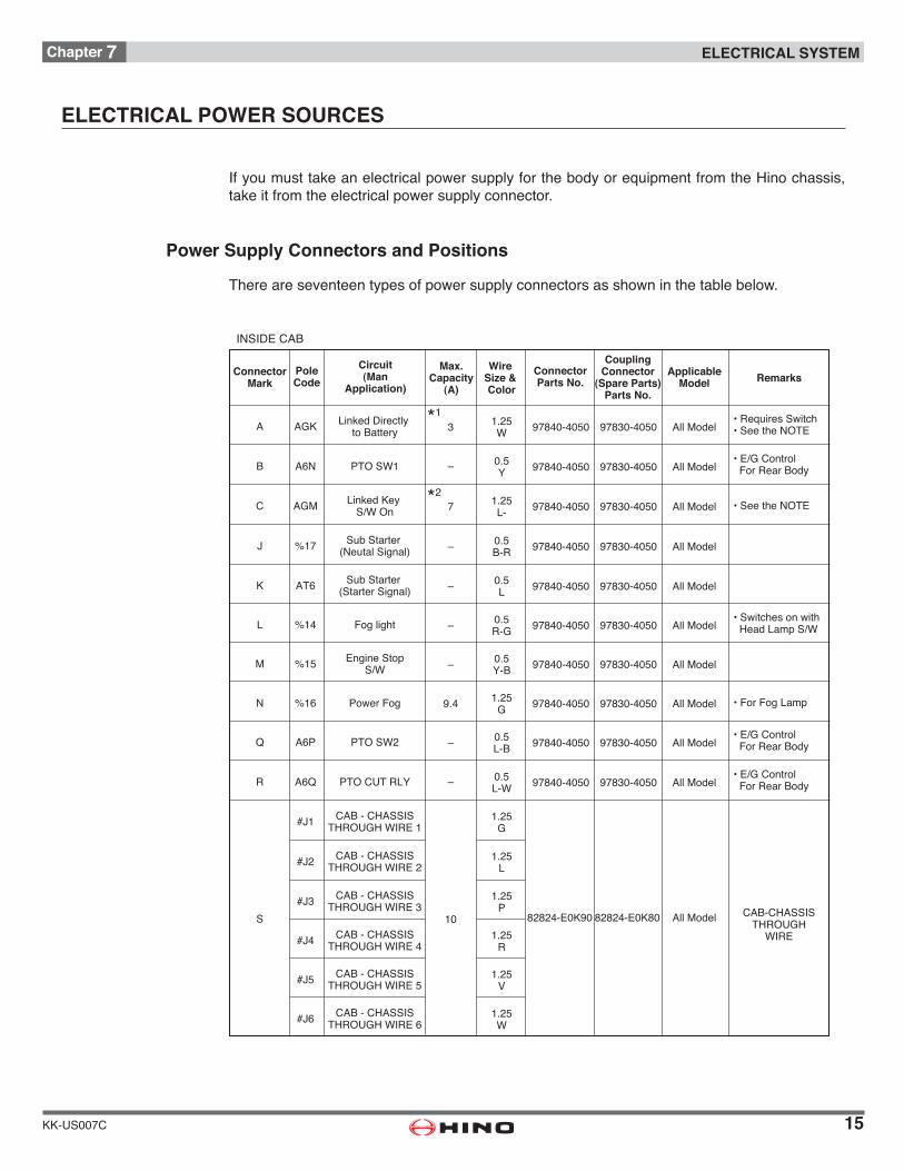
ELECTRICAL POWER SOURCES
If you must take an electrical power supply for the body or equipment from the Hino chassis, take it from the electrical power supply connector.
Power Supply Connectors and Positions
There are seventeen types of power supply connectors as shown in the table below.
INSIDE CAB
ConnectorMark
PoleCode
Circuit(Man
Application)
Max.Capacity
(A)
A AGK Linked Directly to Battery 97840-40503 1.25
W 97830-4050 All Model*1
*2
• E/G Control For Rear Body
• Switches on with Head Lamp S/W
• For Fog Lamp
B –A6N 97840-40500.5Y 97830-4050 All Model
• Requires Switch• See the NOTE
C AGM Linked Key S/W On 97840-40507 1.25
L- 97830-4050 All Model
J %17 Sub Starter (Neutal Signal) 97840-4050– 0.5
B-R 97830-4050 All Model
K AT6 Sub Starter (Starter Signal) 97840-4050– 0.5
L 97830-4050 All Model
L %14 Fog light 97840-4050– 0.5R-G 97830-4050 All Model
M %15 Engine StopS/W 97840-4050– 0.5
Y-B 97830-4050 All Model
N %16 Power Fog 97840-40509.4 1.25G 97830-4050 All Model
• See the NOTE
PTO SW1
Wire Size & Color
ConnectorParts No.
CouplingConnector
(Spare Parts)Parts No.
ApplicableModel Remarks
Q A6P 97840-4050– 0.5L-B 97830-4050 All Model
• E/G Control For Rear Body
CAB-CHASSISTHROUGH
WIRE
R –A6Q 97840-40500.5L-W 97830-4050 All Model
S
#J1 CAB - CHASSISTHROUGH WIRE 1
CAB - CHASSISTHROUGH WIRE 2
82824-E0K9010
1.25G
82824-E0K80 All Model
#J2
CAB - CHASSISTHROUGH WIRE 3
1.25L
#J3
CAB - CHASSISTHROUGH WIRE 4
1.25P
#J4
CAB - CHASSISTHROUGH WIRE 5
CAB - CHASSISTHROUGH WIRE 6
1.25R
#J5 1.25V
#J6 1.25W
PTO CUT RLY
PTO SW2• E/G Control For Rear Body

16
Chapter 7 ELECTRICAL SYSTEM
KK-US007C
CONNECTOR
MARK
POLE
CODE
CIRCUIT
(MAN APPLICATION)
MAX
CAPACITY
(A)
WIRE
SIZE &
COLOR
CONNECTOR
PARTS NO.
COUPLING
CONNECTOR
APPLICABLE
MODELREMARKS
ESQ POWER SUPPLY(BAT) 30.85
W
ESR POWER SUPPLY(ACC) 20.85
GR
ESU EG CTRL DIAG CAN(HI) -0.5
P
ESW VCS CAN(HI) -0.5
Y
EST GND -0.5
BR
ESS POWER SUPPLY(KEY ON) 70.85
L
ESV EG CTRL DIAG CAN(LO) -0.5
V
ESX VCS CAN(LO) -0.5
G
US8281-E0D10
(COLOR:BLUE)S8281-E0D00 ALL MODEL For Telematics
*1
*2
[NOTE]
*1:Totalmax.currentinPoleCodeAGK&ESQ.*2:Totalmax.currentinPoleCodeAGM&ESS.
17
Chapter 7 ELECTRICAL SYSTEM
KK-US007C
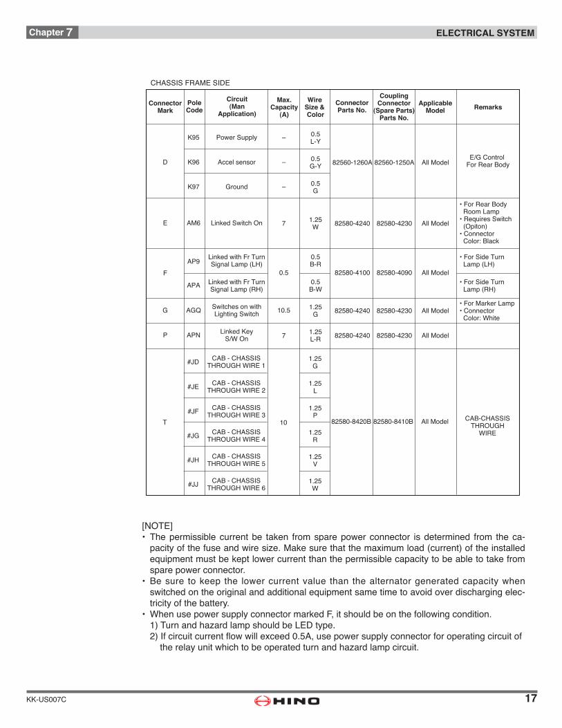
[NOTE]• Thepermissiblecurrentbe taken fromsparepowerconnector isdetermined from theca-pacityofthefuseandwiresize.Makesurethatthemaximumload(current)oftheinstalledequipment must be kept lower current than the permissible capacity to be able to take from spare power connector.
• Be sure to keep the lower current value than thealternator generated capacitywhenswitched on the original and additional equipment same time to avoid over discharging elec-tricity of the battery.
• WhenusepowersupplyconnectormarkedF,itshouldbeonthefollowingcondition. 1)TurnandhazardlampshouldbeLEDtype. 2)Ifcircuitcurrentflowwillexceed0.5A,usepowersupplyconnectorforoperatingcircuitof the relay unit which to be operated turn and hazard lamp circuit.
CHASSIS FRAME SIDE
ConnectorMark
PoleCode
Circuit(Man
Application)
Max.Capacity
(A)
E AM6 Linked Switch On 82580-42407
0.5
1.25W 82580-4230 All Model
G AGQ Switches on withLighting Switch 82580-42401.25
G 82580-4230 All Model10.5
F
• For Rear Body Room Lamp• Requires Switch (Opiton)• Connector Color: Black
• For Marker Lamp• Connector Color: White
Wire Size & Color
ConnectorParts No.
CouplingConnector
(Spare Parts)Parts No.
ApplicableModel Remarks
7P APN Linked KeyS/W On
1.25L-R 82580-423082580-4240 All Model
AP9 Linked with Fr TurnSignal Lamp (LH)
82580-4100
0.5B-R
82580-4090 All Model
• For Side Turn Lamp (LH)
• For Side Turn Lamp (RH)APA Linked with Fr Turn
Signal Lamp (RH)0.5B-W
E/G Control For Rear Body
K97 Ground 0.5G
D –K96 Accel sensor 82560-1260A0.5G-Y 82560-1250A All Model
K95 Power Supply 0.5L-Y
–
–
#JJ
CAB-CHASSISTHROUGH
WIRET
#JD CAB - CHASSISTHROUGH WIRE 1
CAB - CHASSISTHROUGH WIRE 2
82580-8420B10
1.25G
82580-8410B All Model
#JE
CAB - CHASSISTHROUGH WIRE 3
1.25L
#JF
CAB - CHASSISTHROUGH WIRE 4
1.25P
#JG
CAB - CHASSISTHROUGH WIRE 5
CAB - CHASSISTHROUGH WIRE 6
1.25R
#JH 1.25V
1.25W
18
Chapter 7 ELECTRICAL SYSTEM
KK-US007C
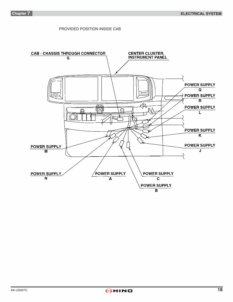
PROVIDED POSITION INSIDE CAB

19
Chapter 7 ELECTRICAL SYSTEM
KK-US007C
POSITION OF TELEMATICS CONNECTOR
UPFR
LH
Blower Motor Relay Panel
Rack of ECU
Blower Motor
Rack of ECU
To Door Harness UPFR
LH
TELEMATICS CONNECTORU
20
Chapter 7 ELECTRICAL SYSTEM
KK-US007C
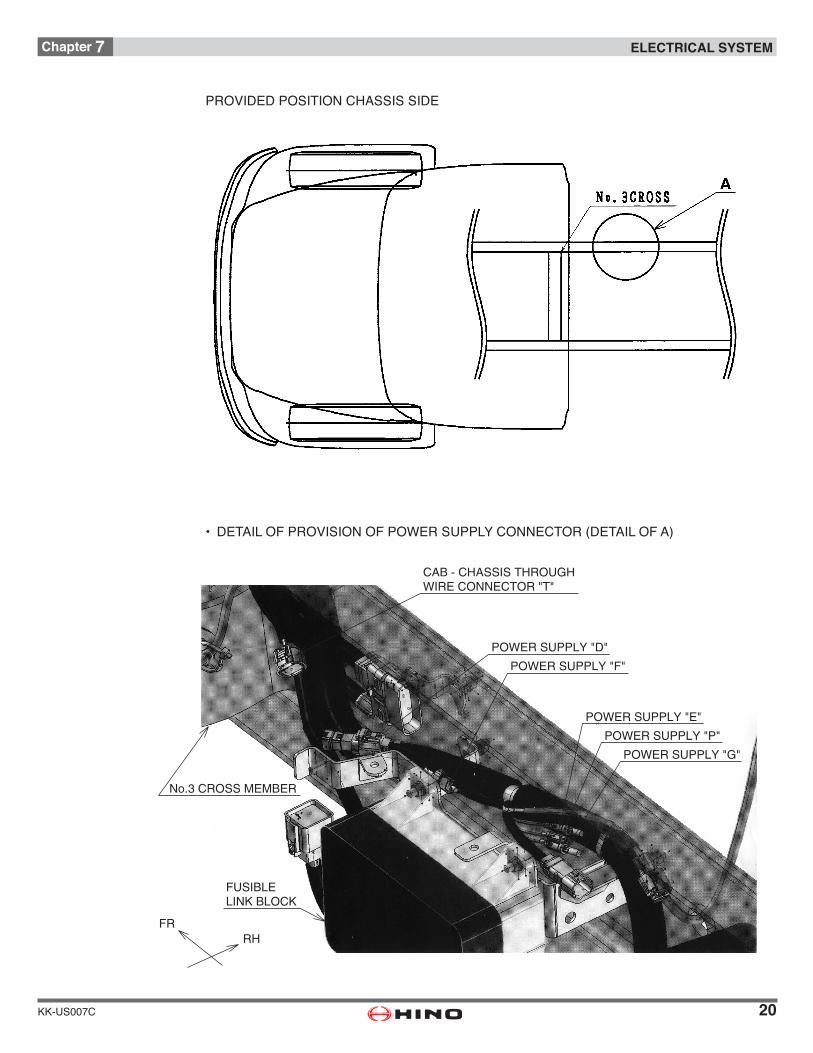
PROVIDED POSITION CHASSIS SIDE
• DETAILOFPROVISIONOFPOWERSUPPLYCONNECTOR(DETAILOFA)
CAB - CHASSIS THROUGHWIRE CONNECTOR "T"
POWER SUPPLY "D"
POWER SUPPLY "F"
POWER SUPPLY "G"
POWER SUPPLY "P"
POWER SUPPLY "E"
No.3 CROSS MEMBER
FRRH
FUSIBLELINK BLOCK
21
Chapter 7 ELECTRICAL SYSTEM
KK-US007C
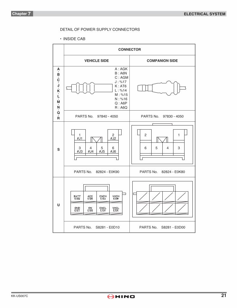
DETAILOFPOWERSUPPLYCONNECTORS
• INSIDECAB
A·B·C·J·K·L·M·N·Q·R PARTS No. 97830 - 4050PARTS No. 97840 - 4050
S
U
PARTS No. 82824 - E0K80PARTS No. 82824 - E0K90
PARTS No. S8281 - E0D00PARTS No. S8281 - E0D10
CONNECTOR
VEHICLE SIDE COMPANION SIDE
A : AGKB : A6NC : AGMJ : %17K : AT6L : %14M : %15N : %16Q : A6PR : A6Q
4#J4
3#J3
5#J5
6#J6
1#J1
2#J2
56 4 3
2 1
22
Chapter 7 ELECTRICAL SYSTEM
KK-US007C
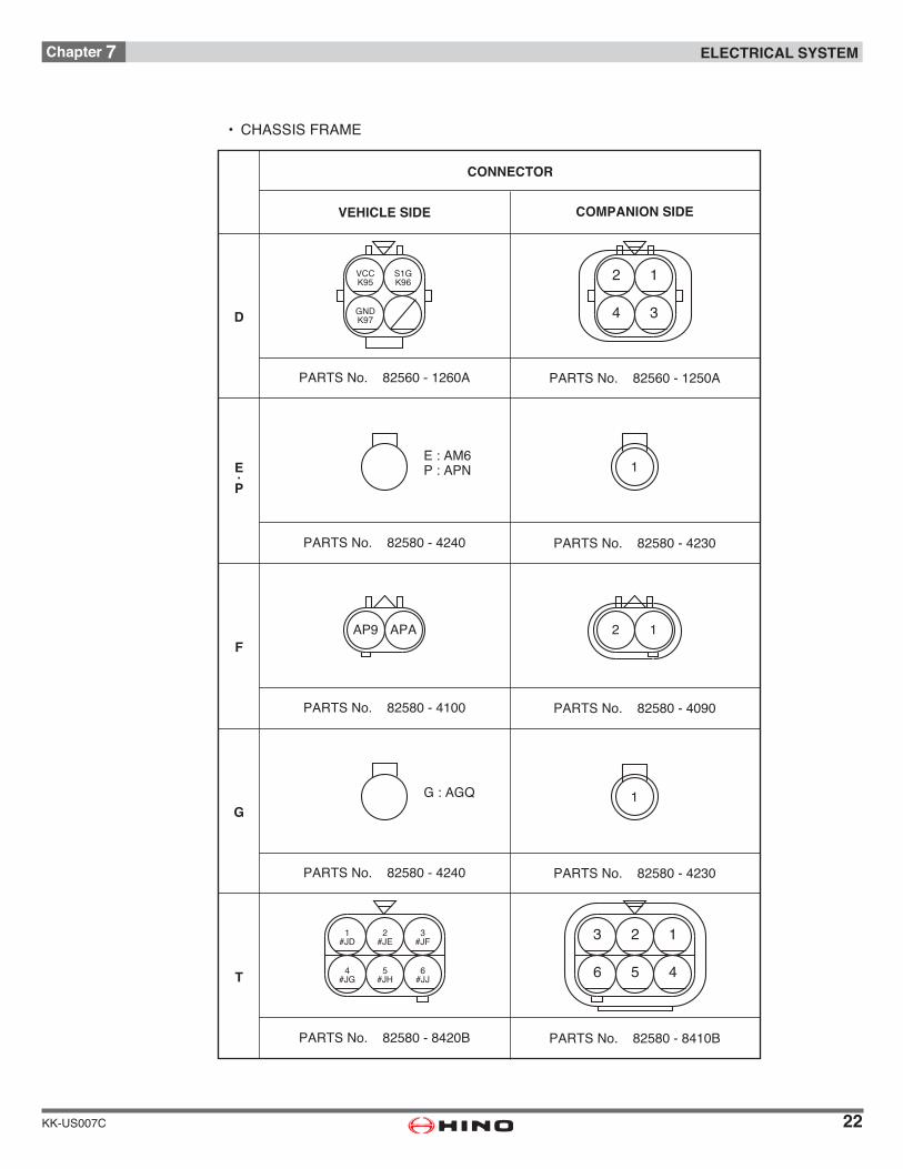
• CHASSISFRAME
CONNECTOR
VEHICLE SIDE COMPANION SIDE
1
PARTS No. 82580 - 4240
G : AGQ
PARTS No. 82580 - 4230
E·P
F
1
PARTS No. 82580 - 4240
E : AM6P : APN
PARTS No. 82580 - 4230
G
PARTS No. 82580 - 8420B PARTS No. 82580 - 8410B
T
PARTS No. 82580 - 4100 PARTS No. 82580 - 4090
D
PARTS No. 82560 - 1260A PARTS No. 82560 - 1250A
2 1AP9 APA
VCCK95
S1GK96
GNDK97
2 1
4 3
1#JD
2#JE
4#JG
3#JF
5#JH
6#JJ
123
456

23
Chapter 7 ELECTRICAL SYSTEM
KK-US007C
HOWTOTAKEELECTRICITYFROMPOWERSUPPLYCONNECTOR
[NOTE]• Asfaraspossibletakepowerusingsub-harnesstype.• Ifyoumusttakepowerusingdirectconnectingtype,besuretoobservetheprecautionsde-scribedhereinaftersection“HARNESSWIRING”.
24
Chapter 7 ELECTRICAL SYSTEM
KK-US007C
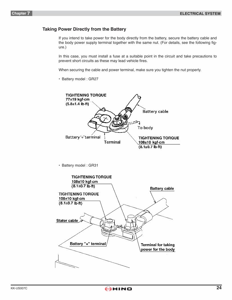
Taking Power Directly from the Battery
If you intend to take power for the body directly from the battery, secure the battery cable and thebodypowersupplyterminaltogetherwiththesamenut.(Fordetails,seethefollowingfig-ure.)
In this case, you must install a fuse at a suitable point in the circuit and take precautions to preventshortcircuitsasthesemayleadvehiclefires.
Whensecuringthecableandpowerterminal,makesureyoutightenthenutproperly.
• Batterymodel:GR27
• Batterymodel:GR31

25
Chapter 7 ELECTRICAL SYSTEM
KK-US007C
Room Lamp Switch, Van Body
Room lamp switch is provided as an optional equipment.Besuretofollowthemannerdescribedinfollowngfigureswheninstalltheswitch.
INSTALLATIONPOSITIONOFSWITCH
[NOTE]•Installtheswitchafter
removed cover plate.

26
Chapter 7 ELECTRICAL SYSTEM
KK-US007C
Detail of Provision of Connector
• Connectorwhichisconnectedwithroomlampswtch,vanbodyisprovidedcenterofdashboardpaneldescribedinfollowngfigure.
• Makesuretoconnectthepowersupplyconnectorwithswitch.

27
Chapter 7 ELECTRICAL SYSTEM
KK-US007C
Precaution for Installing Wires, etc., to Cab
Wheninstallingaharnessetc.throughtheholeoffrontdashpanel,tosecuretherustpreven-tionandwaterproofbeforethesaidtaken-in,carryoutfittingandwiringaccordingtothefol-lowing instructions.• Throughholeø30mm(1.2 in.) isprovidedon the frontdashpanelbut it isclosedwithagrommet.Makeaslitonthisgrommetand,afterthewiring,sufficientlysealitsperipherywitha sealing agent.
• Inordertosecurethewaterproofness,lowerthewiringonceasshownon“SectionA-A”todrain the water and after that bring the wiring into the cab.
• It isprohibitedtofixthewiringwithatappingscrewetc.,becausethiscanbeacauseofpenetration of dust.
28
Chapter 7 ELECTRICAL SYSTEM
KK-US007C
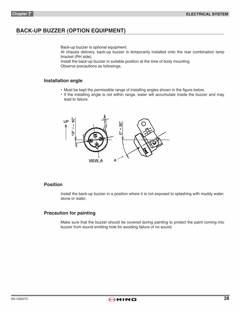
BACK-UP BUZZER (OPTION EQUIPMENT)
Back-up buzzer is optional equipment.At chassis delivery, back-up buzzer is temporarily installed onto the rear combination lamp bracket(RHside).Install the back-up buzzer in suitable position at the time of body mounting.Observe precautions as followings.
Installation angle
• Mustbekeptthepermissiblerangeofinstallinganglesshowninthefigurebelow.• If theinstallingangle isnotwithinrange,waterwillaccumulate insidethebuzzerandmay
lead to failure.
Position
Installtheback-upbuzzerinapositionwhereitisnotexposedtosplashingwithmuddywater,stone or water.
Precaution for painting
Make sure that the buzzer should be covered during painting to protect the paint coming into buzzer from sound emitting hole for avoiding failure of no sound.
29
Chapter 7 ELECTRICAL SYSTEM
KK-US007C
HARNESS WIRING
• Ifamistakeismadeintheharnesswiringwhilemountingabodyorequipment,theharnesswire may be damaged by vehicle vibration while the vehicle is driving, or water, dust, or mud enteringintotheharnesswire.Iftheseoccur,ashort-circuitorfiremayresultcausingase-vere accident.
• Accordingly,besuretoobservetheproceduresgivenbelowformodificationsoralterationsof the harness wire involved with the body mounting or other actions.
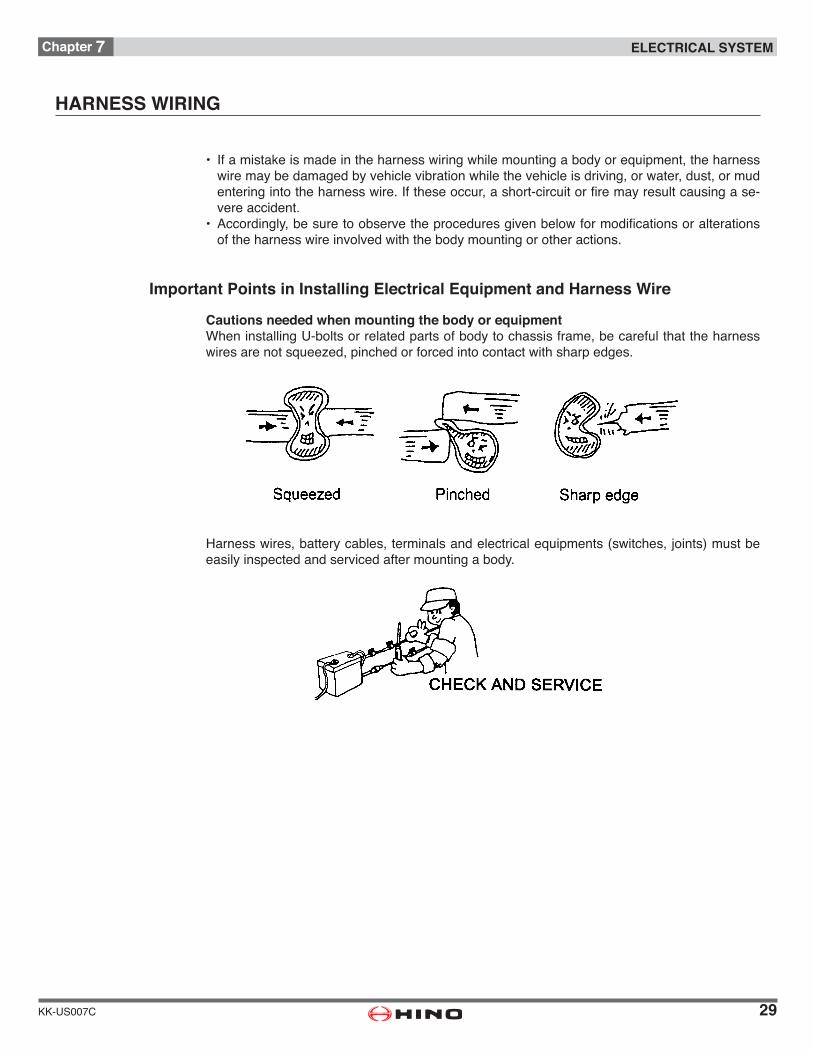
Important Points in Installing Electrical Equipment and Harness Wire
Cautions needed when mounting the body or equipmentWheninstallingU-boltsorrelatedpartsofbodytochassisframe,becarefulthattheharnesswires are not squeezed, pinched or forced into contact with sharp edges.
Harnesswires,batterycables,terminalsandelectricalequipments(switches,joints)mustbeeasily inspected and serviced after mounting a body.
30
Chapter 7 ELECTRICAL SYSTEM
KK-US007C
Ifyouintendedtofitabuzzerforthebody,makesurethat itssoundisclearlydifferentfromthatoftheexistingbuzzeraroundthedriver’sseat.
[SPECIFICATIONOFEXISTINGBUZZERAROUNDDRIVER’SSEAT]
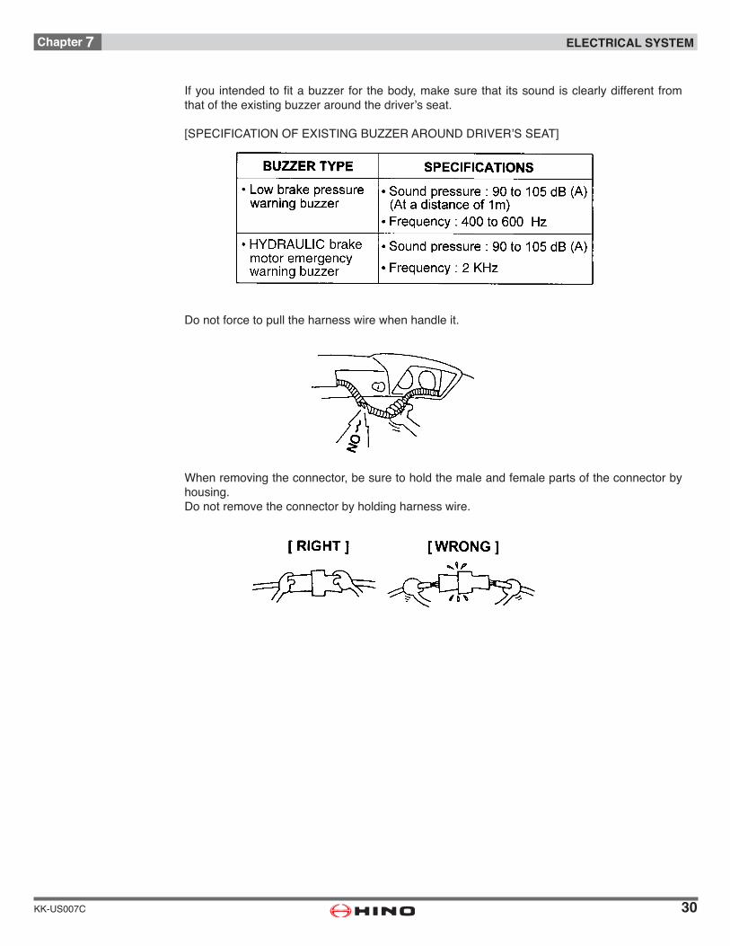
Do not force to pull the harness wire when handle it.
Whenremovingtheconnector,besuretoholdthemaleandfemalepartsoftheconnectorbyhousing.Do not remove the connector by holding harness wire.
31
Chapter 7 ELECTRICAL SYSTEM
KK-US007C
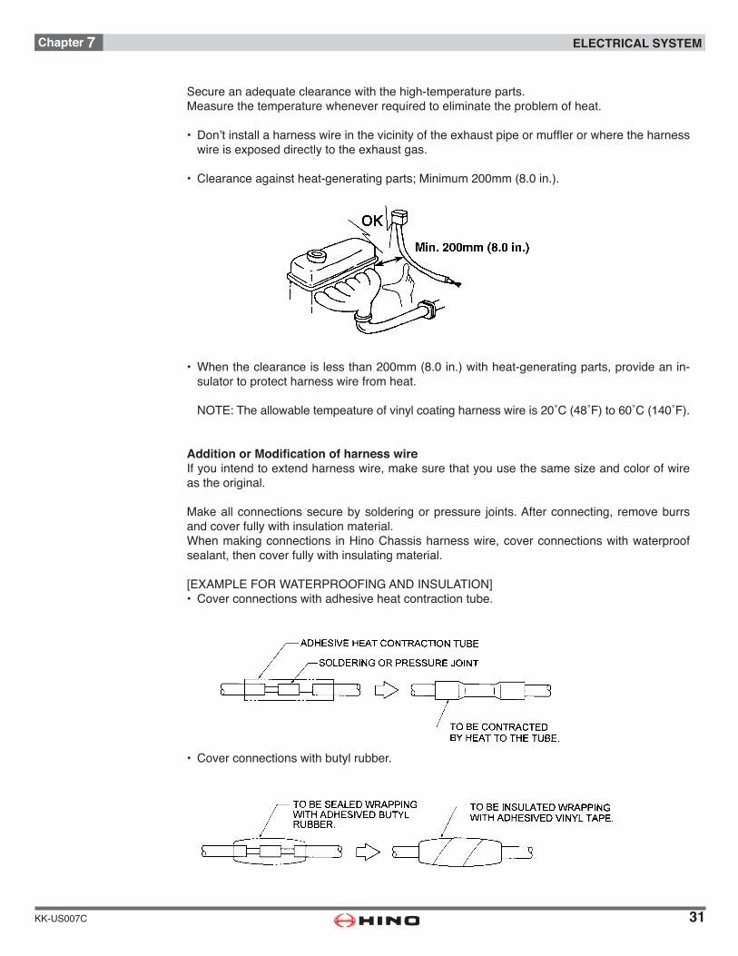
Secure an adequate clearance with the high-temperature parts.Measure the temperature whenever required to eliminate the problem of heat.
• Don’tinstallaharnesswireinthevicinityoftheexhaustpipeormufflerorwheretheharnesswireisexposeddirectlytotheexhaustgas.
• Clearanceagainstheat-generatingparts;Minimum200mm(8.0in.).
• Whentheclearanceislessthan200mm(8.0in.)withheat-generatingparts,provideanin-sulator to protect harness wire from heat.
NOTE:Theallowabletempeatureofvinylcoatingharnesswireis20˚C(48˚F)to60˚C(140˚F).
Addition or Modification of harness wireIfyouintendtoextendharnesswire,makesurethatyouusethesamesizeandcolorofwireas the original.
Makeallconnectionssecurebysolderingorpressure joints.Afterconnecting, removeburrsand cover fully with insulation material.Whenmakingconnections inHinoChassisharnesswire,coverconnectionswithwaterproofsealant, then cover fully with insulating material.
[EXAMPLEFORWATERPROOFINGANDINSULATION]• Coverconnectionswithadhesiveheatcontractiontube.
• Coverconnectionswithbutylrubber.
32
Chapter 7 ELECTRICAL SYSTEM
KK-US007C
Whensoldering,donotusechlorine.
Ifyouintendtomovethebatteryormodifythebatterycablelayout,donotextendorshortenthe battery cable.If youmove thebattery, resistanceof theextendedharnesswire should bebelow45milli-Ohms. Otherwise critical burner failure can be brought.Inareaswherethebatterycablesaresubjecttomovementdue to relative motion of the starter and the side rail, do not modify the clamping method, posi-tions of clamps, or the amount of slack in the cables.
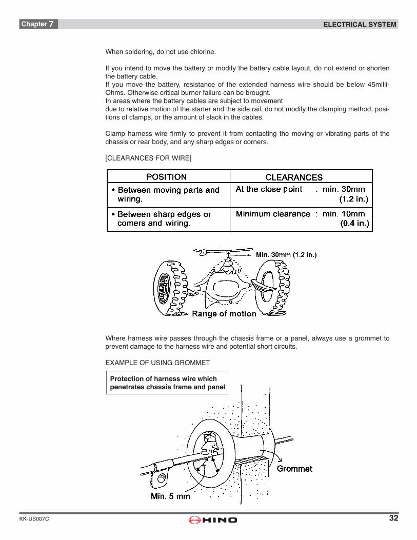
Clampharnesswirefirmly toprevent it fromcontacting themovingorvibratingpartsof thechassis or rear body, and any sharp edges or corners.
[CLEARANCESFORWIRE]
Whereharnesswirepassesthroughthechassisframeorapanel,alwaysuseagrommettoprevent damage to the harness wire and potential short circuits.
EXAMPLEOFUSINGGROMMET
Protection of harness wire which penetrates chassis frame and panel

33
Chapter 7 ELECTRICAL SYSTEM
KK-US007C
Do not install harness wire where it may be damaged by accumulation of mud or snow, by freezing,orbyflyingstones.If you must install harness wire in such positions, protect it with metal plates.
When installingaharnesswire inside thesiderail,place theharnesswirealongalready in-stalled harness wire and do not wire independently along empty spaces.Also,whenwiringunderthefloorofthebodyorinsidetheroofconstruction,besuretoplacethe harness wire along the structure frame, use a clip following the indicated interval, carry out waterproofingmeasuresandobservetheharnesswiringrules.
Do not make connections by cutting open the coating of a wire and pulling out the bare wire. This procedure is very dangerous and may damage other wires.
Plug up the passage hole of a harness wire with a grommet so that water dose not pour in in an electrical equipment along with a harness wire.Make a terminal part higher than the entrance of a harness wire.
34
Chapter 7 ELECTRICAL SYSTEM
KK-US007C
Installharnesswirewheretheyarenotexposedtodustorwater.
Do not install the harness wire on the top or outer side of the chassis frame.Insuchpositions,theymaybedamagedbybeingsteppedonduringbodymounting,orbyfly-ing stones during vehicle operation.
If there is a harness for the chassis already installed close to the wiring area when wiring is done inside the chassis frame, the wiring and taping should be done along this harness.
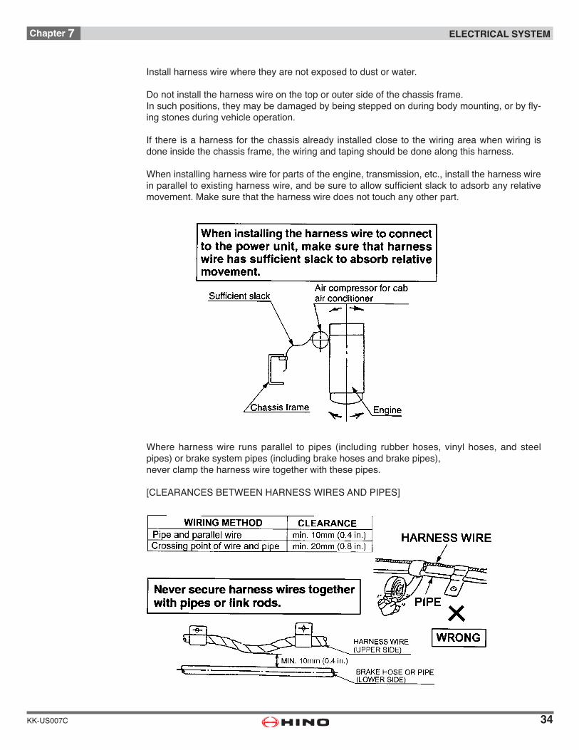
Wheninstallingharnesswireforpartsoftheengine,transmission,etc.,installtheharnesswireinparalleltoexistingharnesswire,andbesuretoallowsufficientslacktoadsorbanyrelativemovement. Make sure that the harness wire does not touch any other part.
Whereharnesswire runsparallel to pipes (including rubber hoses, vinyl hoses, and steelpipes)orbrakesystempipes(includingbrakehosesandbrakepipes),never clamp the harness wire together with these pipes.
[CLEARANCESBETWEENHARNESSWIRESANDPIPES]
35
Chapter 7 ELECTRICAL SYSTEM
KK-US007C
If you move the battery, you may have to temporarily remove the battery cables from the ter-minals of the battery.Whenrefittingthebatterycables,observethespecifiedtorquetoavoiddamagingthebatteryterminal:
(Ifaterminalisdamaged,replaceitwithanewpart.)
Ifyoumovethebattery,makesureitispositionedatleast200mm(8.0in.)awayfromtheex-haustsystem(muffler,tailpipe,etc.).Ifyoumustinstallthebatterywithin200mm(8.0in.)oftheexhaustsystem,protectitwithin-sulating panels.
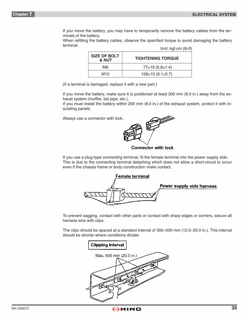
Always use a connector with lock.
Ifyouuseaplug-typeconnectingterminal,fitthefemaleterminalintothepowersupplyside.This is due to the connecting terminal detaching which does not allow a short-circuit to occur even if the chassis frame or body construction make contact.
To prevent sagging, contact with other parts or contact with sharp edges or corners, secure all harness wire with clips.
Theclipsshouldbespacedatastandardintervalof300~500mm(12.0~20.0in.).Thisintervalshould be shorter where conditions dictate.
Unit: kgf·cm (lb·ft)
SIZE OF BOLT & NUT
M8 77±19 (5.8±1.4)
M10 108±10 (8.1±0.7)
TIGHTENING TORQUE

36
Chapter 7 ELECTRICAL SYSTEM
KK-US007C
All clips should use resin coating or attached grommets.
[RECOMMENDED CLIP TYPES]
Crocodile clips and adhesive clips should only be used for temporary installation.
Harness wires should be installed above fuel hoses or pipes to avoid fuel dripping onto the harness wire in the event that a fuel leak occurs.Keepaclearanceofatleast20mm(0.8in.)betweentheharnesswireandfuelhose.
Bundle unused harness wires and their terminals should be bundled with other harness wires and covered with vinyl tape to prevent water from penetrating the terminal.
37
Chapter 7 ELECTRICAL SYSTEM
KK-US007C
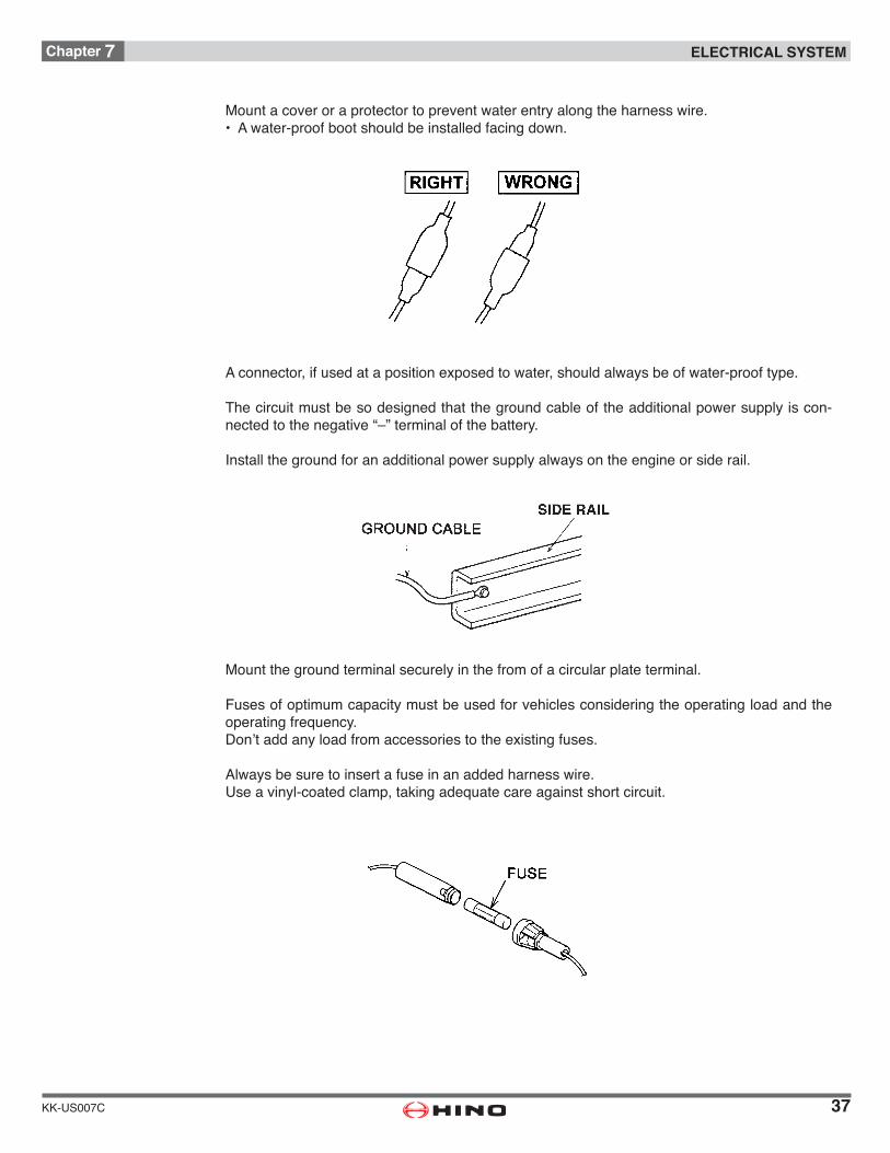
Mount a cover or a protector to prevent water entry along the harness wire.• Awater-proofbootshouldbeinstalledfacingdown.
Aconnector,ifusedatapositionexposedtowater,shouldalwaysbeofwater-prooftype.
The circuit must be so designed that the ground cable of the additional power supply is con-nectedtothenegative“–”terminalofthebattery.
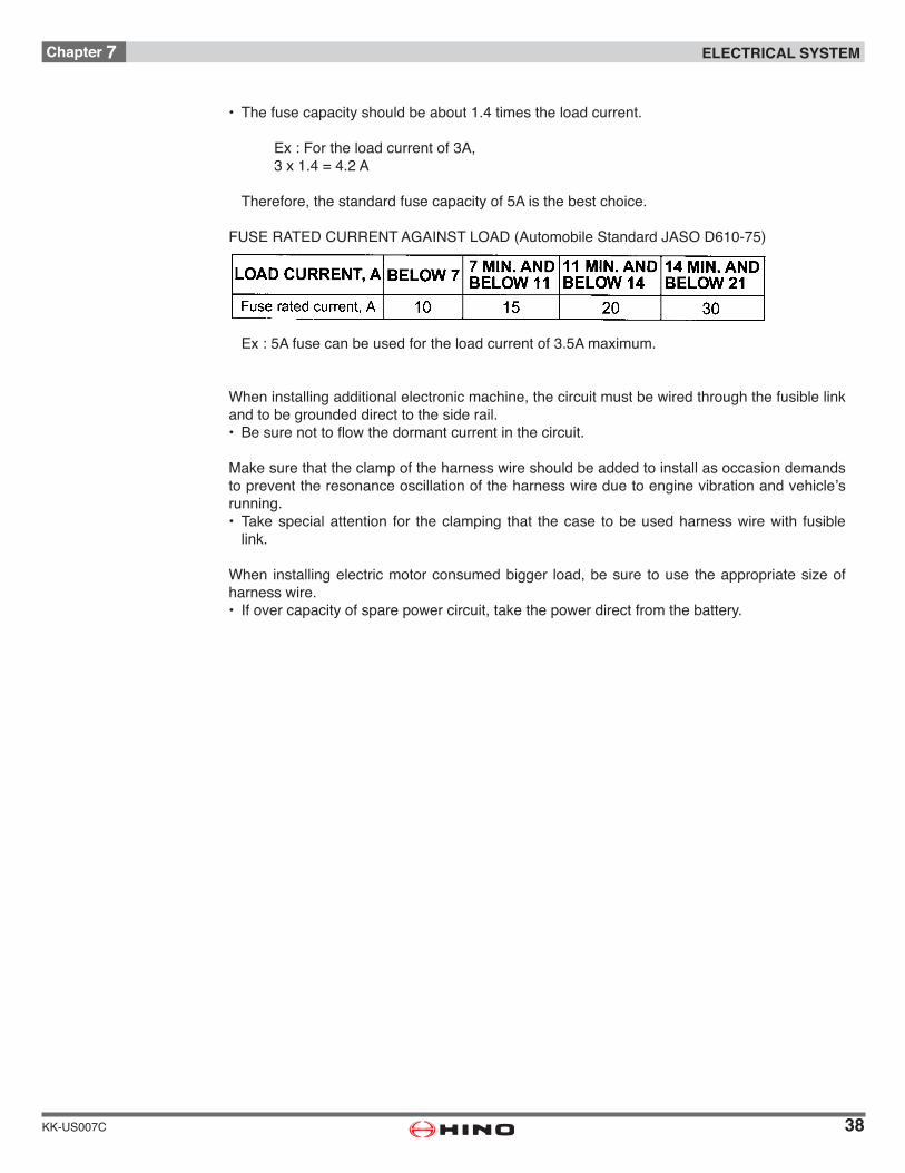
Install the ground for an additional power supply always on the engine or side rail.
Mount the ground terminal securely in the from of a circular plate terminal.
Fuses of optimum capacity must be used for vehicles considering the operating load and the operating frequency.Don’taddanyloadfromaccessoriestotheexistingfuses.
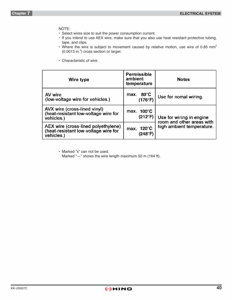
Always be sure to insert a fuse in an added harness wire.Use a vinyl-coated clamp, taking adequate care against short circuit.
38
Chapter 7 ELECTRICAL SYSTEM
KK-US007C
• Thefusecapacityshouldbeabout1.4timestheloadcurrent.
Ex:Fortheloadcurrentof3A, 3x1.4=4.2A
Therefore,thestandardfusecapacityof5Aisthebestchoice.
FUSERATEDCURRENTAGAINSTLOAD(AutomobileStandardJASOD610-75)
Ex:5Afusecanbeusedfortheloadcurrentof3.5Amaximum.
Wheninstallingadditionalelectronicmachine,thecircuitmustbewiredthroughthefusiblelinkand to be grounded direct to the side rail.• Besurenottoflowthedormantcurrentinthecircuit.
Make sure that the clamp of the harness wire should be added to install as occasion demands topreventtheresonanceoscillationoftheharnesswireduetoenginevibrationandvehicle’srunning.• Takespecialattention for theclamping that thecase tobeusedharnesswirewith fusible
link.
When installingelectricmotorconsumedbigger load,besure touse theappropriatesizeofharness wire.• Ifovercapacityofsparepowercircuit,takethepowerdirectfromthebattery.

39
Chapter 7 ELECTRICAL SYSTEM
KK-US007C
Electric Wire Size and Permissible Currents
Wire Size and CurrentsWhenwiringtheharnesswiretogetherwiththebodymountingoperations,selectanappropri-atetypeofharnesswiretakingintoconsiderationthepowerconsumptioncapacity(A)oftheelectrical equipment such will be mounted and the condition of the installation location refer-ring as following table.
WIRE TYPE
WIRE TYPE
WIRE SIZE AND LENGTH
WIRE SIZE AND PERMISSIBLE CURRENT
( A )
CONNECTINGFUSE CAPACITY AMBIENT
TEMPERATURE (0.0008 in. )AV 80˚C (176˚F)
5 AVX 100˚C (212˚F)120˚C (248˚F)
80˚C (176˚F)100˚C (212˚F)120˚C (248˚F)
80˚C (176˚F)100˚C (212˚F)120˚C (248˚F)
80˚C (176˚F)100˚C (212˚F)120˚C (248˚F)
80˚C (176˚F)100˚C (212˚F)120˚C (248˚F)
80˚C (176˚F)100˚C (212˚F)120˚C (248˚F)
80˚C (176˚F)100˚C (212˚F)120˚C (248˚F)
80˚C (176˚F)
100˚C (212˚F)120˚C (248˚F)
80˚C (176˚F)
100˚C (212˚F)120˚C (248˚F)
80˚C (176˚F)
100˚C (212˚F)120˚C (248˚F)
MAX. 30m(MAX. 98 ft)
(MAX. 49 ft) (MAX. 66 ft) (MAX. 98 ft)
(MAX. 49 ft) (MAX. 66 ft) (MAX. 115 ft)
(MAX. 49 ft) (MAX. 82 ft)
(MAX. 16 ft) (MAX. 33 ft) (MAX. 49 ft) (MAX. 82 ft)
(MAX. 16 ft) (MAX. 30 ft) (MAX. 66 ft) (MAX. 66 ft)
(MAX. 23 ft) (MAX. 33 ft) (MAX. 49 ft)
(MAX. 16 ft) (MAX. 33 ft)
(MAX. 33 ft)
(MAX. 131 ft)
— — — — — —AEXAV
10 AVX MAX. 15m MAX. 20m MAX. 30m — — — —AEXAV
15 AVX X MAX. 15m MAX. 20m MAX. 35m — — —AEXAV
20 AVX X X MAX. 15m MAX. 25m MAX. 40m — —AEXAV
30 AVX X X X MAX. 5m MAX. 10m MAX. 15m MAX. 25m
AEXAV
40 AVX X X X MAX. 5m MAX. 9m MAX. 20m MAX. 20m
AEXAV
50 AVX X X X X MAX. 7m MAX. 10m MAX. 15m
AEXAV
60 AVX X X X X X MAX. 5m MAX. 10m
AEXAV
80 AVX X X X X X X MAX. 10m
AEX
AV 9A 11A 14A 20A 27A 36A 47AAVX 8A 10A 13A 17A 24A 33A 43A
AEX 7A 9A 12A 17A 23A 32A 42A
2 (0.0013 in. )2 (0.002 in. )2 (0.0031 in. )2 (0.005 in. )2 (0.008 in. )2 (0.012 in. )2
(0.0008 in. )2 (0.0013 in. )2 (0.002 in. )2 (0.0031 in. )2 (0.005 in. )2 (0.008 in. )2 (0.012 in. )2
0.5mm 0.85mm 1.25mm 2mm 3mm 5mm 8mm2 2 2 2 2 2 2
AMBIENTTEMPERATURE
0.5mm 0.85mm 1.25mm 2mm 3mm 5mm 8mm2 2 2 2 2 2 2
40
Chapter 7 ELECTRICAL SYSTEM
KK-US007C
NOTE:• Selectwiressizetosuitthepowerconsumptioncurrent.• IfyouintendtouseAEXwire,makesurethatyoualsouseheatresistantprotectivetubing,
tape, and clips.• Where thewire is subject tomovement causedby relativemotion, usewire of 0.85mm2 (0.0013in.2)crosssectionorlarger.
• Characteristicofwire.
• Marked“x”cannotbeused. Marked“—”showsthewirelengthmaximum50m(164ft).

41
Chapter 7 ELECTRICAL SYSTEM
KK-US007C
Coding for Electrical WiresWirecodesrepresentsizeandcolor