chapter 7insaat.ege.edu.tr/uploads/d339_testing_chpter7.pdfchapter 7 characteristics of ... in the...
TRANSCRIPT

1
CHAPTER 7
Characteristics of
Mechanical Tests

2
7.1 Static Tension
A simple tension test is accomplished by gripping opposite ends of the piece of material and pulling it apart.
The use of tension test is largely determined by the type of service to which a material is to be subjected.
Metals and plastics generally exhibit relatively high tenacity for resisting tensile loads.
3
Specimens for tensile tests
Tensile strength test procedures are used to determine the properties of;
wire, reinforcement bars
rod, fibers
tubing, fabrics
The cross section of the specimen is usually round, square or rectangular.
The central portion of the length is usually (but not always) of smaller cross section than the end portions in order to cause failure at a section where the stresses are not affected by the gripping device.

4
Specimens for tensile tests
The gage length is the marked on which elongation or extensometer measurements are made.
The shape of the ends should be suitable to the material and fit properly to the gripping device.
The ends of the round specimens may be plain, shouldered or threaded.
5
Specimens for tensile test
The percent elongation (or strain) of a ductile metal specimen of given diameter depends on the gage length over which the measurements are made.
For small cylindrical specimens for ductile materials, ASTM (E8) calls for a gage length of four times the diameter.
TS 138 EN 10002-1 “Metallic materials- Tensile testing- Part 1: Method of test at ambient temperature” is the standard test method to obtain the tensile strength of reinforcement bars and other metallic materials of construction.
ASTM standards and TS 138 use specified gage length and thickness or diameter as a base.
6
The properties obtained by
tensile strength test
In the commercial tension test of metals the properties usually determined are:
• yield strength (yield point of ductile materials),
• tensile strength,
• ductility (elongation and reduction in area),
• type of fracture.
For brittle materials, only the tensile strength and character of fracture are commonly determined.
In more complete tests, determinations of stress-strain relations, modulus of elasticity and other mechanical properties are included.

7

8
Application of tensile strength test
Prior to applying the load to a specimen, diameter or width and the thickness of the critical section are measured.
If elongation measurements are to be made, the gage lengths are marked very light so as not to damage the metal and influence the break.
The speed of testing should not be greater than the rate at which the load and other readings can be made with the desired degree of accuracy.
9
Elongation & Reduction in area
After the specimen has failed, it is removed from the testing machine, and if elongation values are needed, the broken ends of a specimen are fitted together and the distance between gage points is measured to the nearest 0.2 mm. The diameter of the smallest section is calipered for determining the reduction in area.
The elongation is the increase in gage length, expressed as a ratio of the original gage length. The reduction in area is the difference between the area of smallest cross section (at the break) and the original cross-sectional area, expressed as a ratio of the original cross-sectional area.

10
Tensile fracture types
Ductile metals experience observable plastic deformation prior to fracture. Brittle metals experience little or no plastic deformation prior to fracture.
Some metals behave in a transitional manner - partially ductile/brittle.
Ductile fracture has dimpled, cup-cone fracture appearance. The dimples can become elongated by a lateral shearing force, or the crack may be in the opening (tearing) mode.
Brittle fracture displays either cleavage or intergranular fracture.
A description of the fracture type should be given in every test report.

11
Comparison of Breaks.
Steel
neck down
break
Aluminum
45 degree
break
Cast iron
straight break

12
Effect of size of the specimen
on tensile strength test
The size and shape of a specimen affect the
mechanical properties of a metal to a different
degree.
If the metal is of uniform quality, the size of
geometrically similar specimens does not
appreciably affect the results of the tension test.
The diameter and the gage length of the piece must
be fixed for obtaining comparable elongations on
metal specimens.

13
7.2 Static Compression
Compressive strength is the most significant
strength for concrete since the concrete
members are primarily designed for
compressive loads.
Furthermore, some reliable correlations exist
between the compressive strength and
other strengths and properties of practical
significance.

14
Concrete Compressive Strength Test-
Cylinder samples

15
Concrete Compressive Strength Test-Cube
samples

16
Standard specimens for concrete
compressive strengh test
For concrete, the standard specimens used in USA are cylinders twice the diameter in height which changes with the maximum aggregate size Dmax:
Dmax< 50 mm 150x300 mm
Dmax < 65 mm 200x400 mm
Dmax < 150 mm (mass concrete) 450x900mm
In Europe (Turkey) 150mm cubes or 150x300mm cylinders are chosen as the standard specimens.
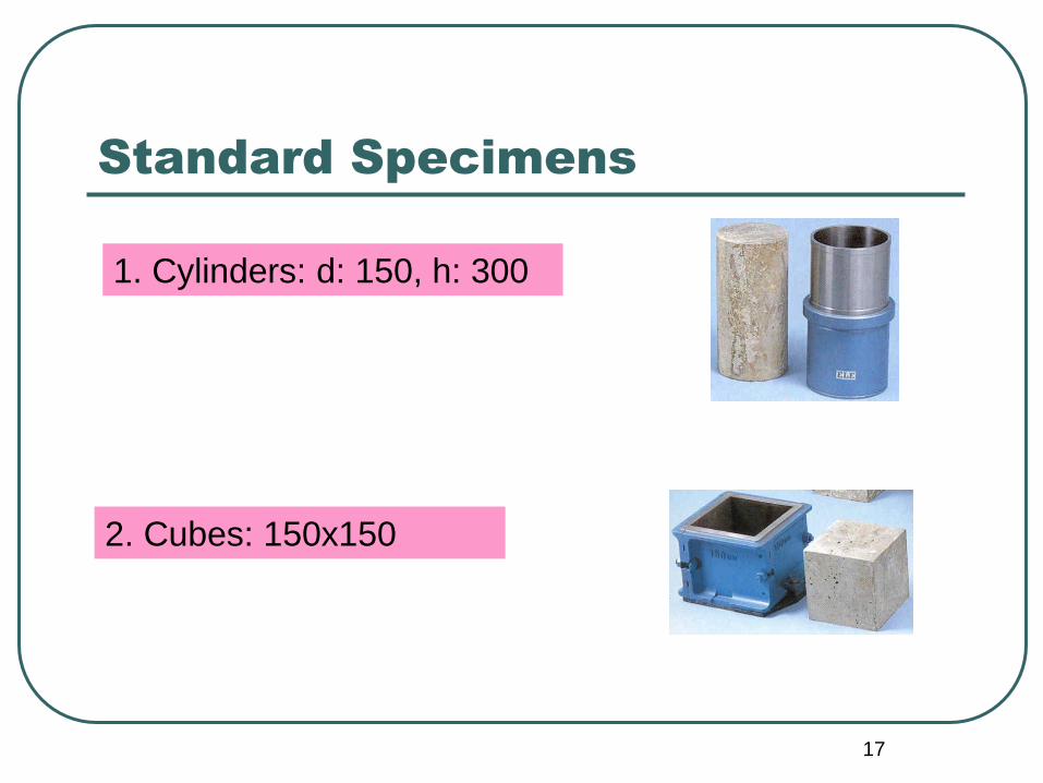
17
1. Cylinders: d: 150, h: 300
2. Cubes: 150x150
Standard Specimens
18
Standard specimens for mortar
and wood
For compressive strength testing of mortars ASTM specifies cubes of 50 mm dimensions, however, EN specifies the use of 40x40x160 mm for bending test and the use of 40 mm modified cubes for compressive strength tests.
Specimens for compression tests of small pieces of wood parallel to the grain are 50x50x200 mm rectangular prisms.
Compression tests perpendicular to the grain are made on nominal 50x50x150mm specimens. The load is applied through a metal bearing plate 50 mm width placed across the upper surface.

19
Compression test of wood
perpendicular to the grain

20
Bearing Plates
Bearing plates should be flat and parallel surfaces which should also be strong and hard relative to the test specimen.
Usually one end of the specimen should bear on a spherically seated block.
The purpose of the block is to overcome the effect of a small lack of parallelism between the head of the machine and the end face of the specimen.
It is desirable that the spherically seated bearing block be at the upper end of the specimen. The specimen should be centered with respect to the center of the spherical surface.

21
Spherical bearing blocks for
compression tests
Spherical
seat
Concrete
specimen
22
Test Procedure
In commercial tests, the only property determined is the compressive strength. The dimensions of the test specimens should be determined with appropriate precision. Metals: to the nearest 0.02 mm, concrete and wood: to the nearest 0.2 mm.
The rate of loading of the compressive strength test should be within 1.4-3.5 kgf/cm2/sec.
Above the practical range, increasing the test speed increases the ultimate strength, while decreasing the test speed reduces it due to creep effect.

23
Types of failure of brittle
materials under compression
Brittle materials commonly
rupture either along a
diagonal plane, or with a
cone- (cylindrical
specimens) or a pyramidal-
(square specimen) shaped
fracture, sometimes called
an hourglass fracture.
Shear
cone or
hourglass
(mortar or
stone
cubes)

24
Mohr’s Theory of Rupture
A material that resists deformation and failure by internal friction as well as by cohesion and that behaves in accordance with the Mohr theory of rupture, the angle of rupture is not 45o (the plane of maximum stress) but is a function of the internal friction angle ; the angle which the plane of failure makes with the axis of loading is equal to 45 - /2.
The internal friction angle for cast iron, sandstone, brick and concrete is approximately 20° for specimens long enough for normal failure surfaces to develop.

25
Relation between angle of
rupture& angle of friction

26
Deviation from the theory
The behavior of materials such as iron, concrete or ceramics do not conform exactly to Mohr’s theory due to two main reasons:
• Their nonhomogeneous composition causes irregularities in the stress pattern.
• The angle of rupture may deviate from the theoretical value due to the stress conditions induced in the end portions of compression specimens by restraint to lateral expansion caused by friction of the bearing plates on the end surfaces.
The second effect is more pronounced for the short specimens
27
If the specimen is so short that a normal failure plane cannot develop within its length, then the strength is appreciably increased, and other types of failure, such as crushing may occur.
With brittle materials in short specimens, when there is a combination of high compressive strength and unrestrained lateral expansion at the ends, the pieces often fail by separation into columnar fragments, known as splitting failure or columnar fracture.

28
Wood under compression
Wood under compressive loading exhibits a behavior
peculiar unto itself. It is an isotropic material
composed of cells formed by organic growth that
align themselves to form a series of tubes and
columns in the direction of the grain.
As a result of this structure, its elastic limit is relatively
low without any definite yield point. These
properties vary with the orientation of the load with
respect to the direction of grain.

29
Wood under compression
For loads normal to the grain, the load that causes
lateral collapse of the tubes or fibers is the
significant load.
For loads parallel to the grain, the elastic strength as
well as the strength at rupture is of importance.
Ductile and plastic materials bulge laterally and take
on a barrel shape as they are compressed,
provided that the specimen does not bend or
buckle.

30
Types of failure of wood under
compression paralled to grain

31
Effect of Specimen Shape&Size
For uniform stressing of the compression specimen, a circular cross section is preferred, square or rectangular shapes are often used.
The selection of the ratio of height to diameter of a compression specimen is of importance.
The effect of frictional restraint at the ends of the specimen (end-effect) becomes unimportant by increasing h/d ratio.
h/d: 2 is commonly employed.

32
Effect of height of concrete on
strength
80
100
120
140
160
180
200
0 1 2 3 4
h/d ratio
Rela
tive c
om
pre
ssiv
e s
tr.
%

33
The actual size of the specimen depends on the type of the material, the type of the measurements to be made and the testing apparatus available.
The ends to which the load is applied should be flat and perpendicular to the axis of the specimen or made so by using caps or adjustable bearing devices.
It is desirable for the capping material to have a modulus of elasticity and strength at least equal to that of the material of the specimen. The cap should be as thin as is practicable (3-5 mm).
Effect of Specimen Shape&Size

34
Effect of size on concrete
cylinders on strength

35
7.3 Shear Tests
A shearing stress acts parallel to a plane,
as distinguished from tensile and
compressive stresses, which act normal
to a plane.
Loadings causing shear conditions:
• Direct shear
• Torsion shear

36
Direct Shear
If the resultants of parallel but opposed
forces act through the centroids of sections
that are spaced very small distances apart,
the shearing stresses over the sections
would be uniform and a state of pure direct
shear would exist.
This condition may be approached but is
never realized practically.

37
Direct shear loadings
Rivet in double shear Wood block in single shear

38
Direct Shear Test
For the direct shear of metals, a bar is usually sheared in some device that clamps a portion of the specimen while the remaining portion is subjected to load by means of suitable dies.
In the direct shear test, the testing device should hold the specimen firmly and preserve good alignment, the load should be applied at right angles to the axis of the piece.
The only critical value that can be observed in the direct shear test is the maximum load P. If A is the area subjected to the force, then the average shearing strength is taken as P/A. The shape and the fractured surface of the specimen should be reported.

39
Methods of testing metals in
direct shear

40
Torsion
The applied forces are parallel and opposite but
do not lie in a plane of longitudinal axis of the
body, thus a couple is set up that produces a
twist about a longitudinal axis.
Torsional shearing stresses on circular cross
sections vary from zero at the axis of twist to a
maximum at the extreme fibers.

41
Torsional loading
42
Torsion Test
The purpose of torsion tests is usually
parallel to those for tension tests.
Often used for testing brittle materials and
can be tested in full-sized parts, i.e.
axles and twist drills which are subjected
to torsional loading in service.
43
Apparatus for torsion tests
Although some UTMs have torsional capacity,
special testing machines for torsion testing are
available. Torsion-testing equipment consists of:
1) A twisting head, with a chuck for gripping the
specimen and for applying the twisting moment to
the specimen.
2) A weight head, which grips the other end of the
specimen and measures the twisting moment of
torque.

44
Torsion test macines

45
Torsion test specimens
A circular cross section specimen is
normally used since in the elastic range,
shear stress varies linearly from a value
zero at the centre of the bar to a
maximum value at the surface.
Thin-walled tubular specimens are
frequently used.

46
Test procedure
A twisting moment is applied to the specimen and the torque is measured.
The angular displacement (or degree of rotation) of a point near one end of the test section of the specimen with respect to a point on the same longitudinal element at the opposite end is determined by using a troptometer (twistmeter).

47
The shear strain γ is given by
Θ: is the angle of twist or degree of rotation, radian
L: is the test length of the specimen
r: radius of the specimen
In the elastic range, the extreme fiber stress т is related to the torque T by the torsion formula for circular shafts:
т: shear stress, Pa
T: torque (or torsional moment), Nm
r: radius of the bar, m
J: polar moment of inertia, m4
J
Tr

48
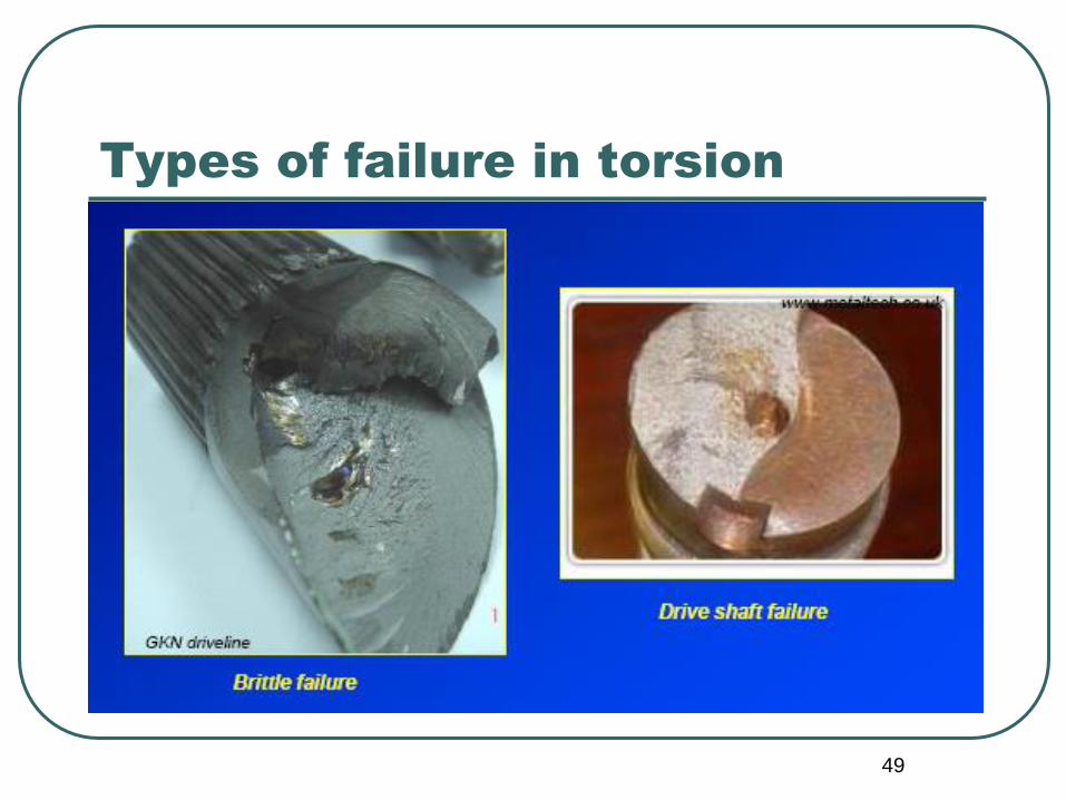
Types of failure in torsion
Solid bar-
ductile
material
Solid bar-
brittle
material
49
Types of failure in torsion

50
7.4 Static Bending
If forces act on a piece of material in such
a way that they tend to induce
compressive stresses over one part of a
cross section of the piece and tensile
stresses over the remaining part, the
piece is said to be in bending.
Bending action in beams is often referred
to as flexure.

51
The variations in total transverse shear
and in bending moment along a beam
are commonly represented by shear and
moment diagrams.
It should be noted that symmetrical two
point loading given a condition of pure
bending (constant moment) over the
central portion of the span.

52
Shear and moment diagrams

53
Scope of Bending Tests
Most structures and machines have members
whose primary function are to resist loads that
cause bending; e.g., beams, slabs and
columns under eccentric loads.
The design of such members is based on tensile,
compressive and shearing properties
accounted for in various bending formulas. The
bending test may serve as a direct means of
evaluating behavior under bending loads.
54
Scope of Bending Tests
Bending test is often as a control test for
brittle materials such as cast iron and
concrete.
For wire and sheet metals relative flexibility
may be measured by a simple bend test.

55
Specimens in Bending Test
A beam to be tested in flexural failure must be so proportioned that it does not fail by lateral buckling or in shear before the ultimate flexural strength is reached.
In order to avoid shear failure, the span must not be too short with respect to its depth.
L = 6d, L=12d where L: length, d: depth
Against lateral buckling: L<15b where b: width
Standardized specimens are used for routine testing of common materials such as concrete, iron, brick and wood.

56
Test Apparatus
Many flexure tests are conducted in UTMs with the supports placed on the platen and with the loading block fastened under the movable head. Some hand-operated machines are also employed.
Fiber strains are measured by deformeters or strainometers supported to the bending fixture or the beam itself.
Test speeds should be planned so that the readings can be taken accurately.

57
Third-point loading

58
Center loading
59
Rupture
The failure of beams of brittle materials such as iron and plain concrete always occurs by sudden rupture.
Failure finally occurs in the tensile fibers, the ratio of tensile to compressive strength is ~25% for cast iron and ~10% for concrete. Ultimate tensile strength of such materials measured by bending test is referred to as flexural tensile strength.
For beams of brittle material, the nominal fiber stress at rupture as computed by the flexure formula (the modulus of rupture in bending) is usually greater than the true tensile strength of the material. The ratio of modulus of rupture to the true tensile strength is ~1.8 for cast iron and ~1.5 to 2 for concrete.

60
Effect of Loading type in
bending test
The relative magnitudes of the modulus of
rupture for three common types of loading are
as follows:
1. In a simple span, the largest value of the
modulus of rupture is obtained from center
loading.
2. Third point loading on a simple span gives
results somewhat less than center-point
loading (~10-15%).
61
7.4 Hardness
Hardness refers to various properties of
solid matter that gives it high resistance
to various kinds of shape change when
force is applied.
There is no single measure of hardness,
however there are different definitions of
hardness.

62
Definitions of Hardness
1. Resistance to permanent indentation under
static and dynamic loads – indentation hardness
2. Energy absorption under impact loads- rebound
hardness
3. Resistance to scratching- scratch hardness
4. Resistance to abrasion-wear hardness
5. Resistance to cutting or drilling- machinability

63
Results of a hardness test may
be utilized as follows:
1. It should be noted that a hardness number cannot be utilized directly in design and analysis, for example, rebound hammer (Schmidt hammer) test results do not indicate the compressive strength of concrete.
2. The quality level of materials or products may be checked or controlled by hardness tests. They may be applied to determine the uniformity of samples of a material or the uniformity of some treatment such as surface hardening, alloying, heat-treatment etc.
3. By establishing a correlation between hardness and some other desired property, e.g., tensile strength, simple hardness tests may serve to control the uniformity of the tensile strength and to indicate rapidly whether more complete tests are warranted.

64
Indentation Hardness Tests
Hardness measurement by resistance to indentation is the basis for a variety of instruments. The indenter, either a ball or a plain or truncated cone or pyramid, is usually made of hard steel or diamond.
Either the load that produces a given depth of indentation or the indentation produced under a given load can be measured.
The loads may be applied either static or dynamic ways. In dynamic tests, the force is developed by a drop or a spring load and the height of rebound of the indenter is taken as a measure of hardness.

65
Hardness Tests
Most commonly used hardness tests for
metals are Brinell and Rockwell tests.
Increased use of very hard steels or hardened
steel surfaces has brought into use of
several other tests, e.g., Shore scleroscope,
Vickers, Monotron, Rockwell superficial and
Herbert machines.

66
Static Hardness Tests/a.Brinell Test
Exerting a static load on an indenter deforms the specimen.
10mm hardened steel ball is used
Load exerted by a mass of ;
• 3000 kg for hard metals,
• 1500 kg for metals of intermediate hardness,
• 500 kg for soft metals.

67
Brinell Test
)(2
22iDDDD
FBHN

68
b. Rockwell Test
Similar to Brinell test, the hardness number is a
function of the degree of indentation of the
test piece by action of an indenter under a
given static load.
This test differs from Brinell test in that the
indenters and load are smaller (60, 100, or
150 kg) and the resulting indentation is
smaller and shallower.

69
Rockwell Test

70
c. Vickers Test
An indentation is made and the hardness
number is determined from the ratio P/A of
the load exerted by a mass P (kg) to the
contact surface area A (mm2) of the
indentation.
The indenter is a square based diamond
pyramid, the mass varies between 1-120 kg.

71
Vickers Test

72
d. Other Static Hardness Tests
Monotron hardness test measures the pressure in kg/mm2 necessary to give a fixed indentation depth of 45 μm.
Microhardness testers such as Knoop indenter is used to determine the hardness of a material over a very small area.
A static ball indentation test is standardized for use with wood, but its usage is not common.

73
Dynamic Hardness Tests/
a.Shore scleroscope
The hardness measured by this instrument is
often referred to as rebound hardness.
Scleroscope hardness is expressed by a
number given by the height of rebound of a
small pointed hammer after falling within a
glass tube from a height of 254 mm against
the surface of the specimen.

74
Shore Scleroscope

75
b. Schmidt Hammer
A Schmidt hammer is a device to measure the surface hardness of concrete or rock. The hammer measures the rebound of a spring loaded mass impacting against the surface of the sample. When conducting the test the hammer should be held at right angles to the surface which in turn should be flat and smooth.
The rebound reading will be affected by the orientation of the hammer, when used in a vertical position gravity will increase the rebound distance of the mass and vice versa for a test conducted on a floor slab.

76
Types of Schmidt Hammer
Classified according to
their impact energy:
Type L-0.735 Nm
Type N-2.207 Nm
Type M-29.43 Nm

77
Schmidt Hammer
Schmidt hammer should be calibrated using a calibration test anvil supplied by the manufacturer for that purpose.
The average of 15 readings should be obtained.
Using this method of testing is classed as indirect as it does not give a direct measurement of the strength of the material.
It simply gives an indication based on surface properties, it is only suitable for making comparisons between samples.

78
Wear-Hardness Tests
Abrasion or wear tests have found their principal use in
connection with paving materials, a number of tests
are standardized.
Abrasion resistance of concrete may be determined by
sand blast method (TS 3262).
For mineral aggregates or brick, the resistance to
degradation or abrasion resistance may be
determined by use of Los Angeles machine (TS EN
1097-2).

79
Scratch Hardness Tests
For a qualitative classification of materials over a wide range, perhaps the most applicable type of test is the scratch test:
A scale is set up in terms of several materials, each of which will just scratch the material of next lower hardness number.
Mohs’ Scale
Hardness No Reference Material
1 Talc
2 Gypsum
3 Calcite
4 Fluorite
5 Apatite
6 Feldspar (orthoclase)
7 Quartz
8 Topaz
9 Sapphire or Corundum
10 Diamond
80
7.5 Impact
An important type of dynamic loading is that in which the load is applied suddenly, as from the impact of a moving mass.
The energy of a blow may be absorbed in a number of ways, through:
- elastic deformation,
- plastic deformation,
- histeresis effects in the parts,
- frictional action between parts and,
- effects of inertia of moving parts.

81
7.5 Impact
In the design of many types of structures that must take impact loading, the aim is to provide for the absorption of as much energy as possible through elastic action.
In such structures, the resilience of the material is a significant property.
In most tests to determine the energy-absorption characteristics of materials under impact loads, the object is to utilize the energy to cause rupture (toughness) of the test piece.

82
Impact
Toughness depends fundamentally on strength and ductility and appears to be independent of the type of loading.
However, the rate at which the energy is absorbed may markedly affect the behavior of a material, different (more or less) measures of toughness may be obtained from impact loadings than from static loadings.

83
Impact resistance of materials
The form of a piece may have a marked effect on its capacity to resist impact loads.
In order to induce fracture to take place under a single blow, test specimens of a ductile material are notched. The use of a notch causes high localized stress concentrations, causes most of the energy of rupture to be absorbed in a localized region of the piece and tends to induce a brittle type of fracture.
The tendency of a ductile material to act like a brittle material when broken in the form of a notched specimen is referred to as notch sensitivity.

84
Types of Impact Tests
In an impact test, the load may be applied in
flexure, tension, compression or torsion.
The impact blow may be delivered through
the use of;
• a dropping weight,
• a swinging pendulum, (Izod and Charpy
tests)
• a rotating flywheel.
85
Pendulum Devices
The principle features of a single-blow pendulum impact machine are:
1. a moving mass whose kinetic energy is great enough to cause rupture of the test specimen placed in its part,
2. an anvil and a support on which the specimen is placed to receive the blow,
3. a means for measuring the residual energy of the moving mass after the specimen has been broken.
86
Pendulum Principle
In pendulum tests, calculation of the energy required for fracture is of primary importance.
Energy loss due to friction or air resistance of the pendulum is generally less than 1% in quality machines.

87
Pendulum Principle
Initial energy :
Ei=m g a = W a
Energy after rupture:
Er=m g b = W b
Energy absorbed by impact:
Eabs=m g (a - b) = W (a - b)
a = R (1 – cos α)
b = R (1 - cos β)
88
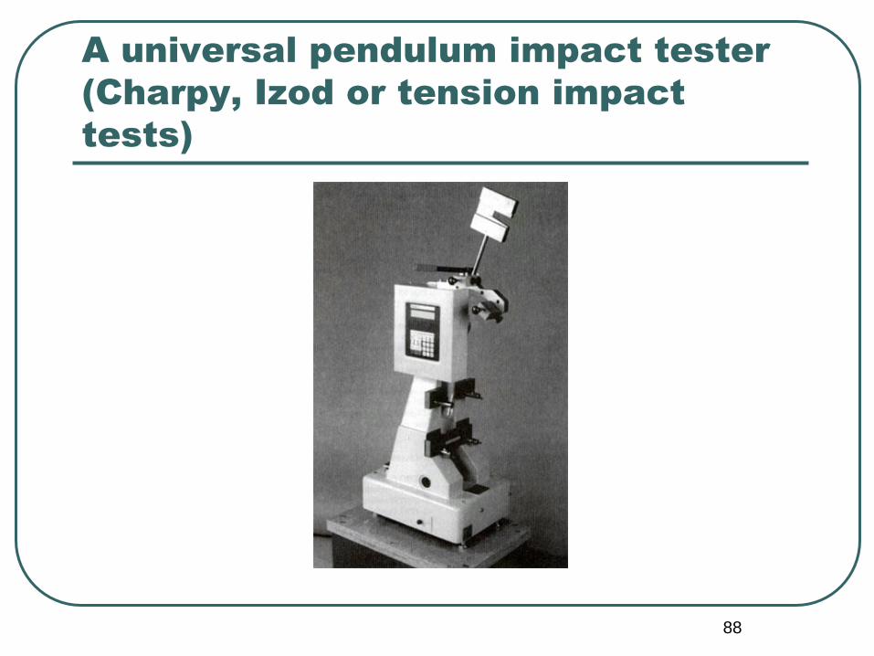
A universal pendulum impact tester
(Charpy, Izod or tension impact
tests)

89
Charpy & Izod Tests
These tests are made on small notched specimens
broken in flexure.
In the Charpy test, the specimen is supported as a
single beam and in the Izod test, it is supported
as a cantilever.
These tests do not simulate shock loading in
service, they simply give the relative resistance
of a particular notched metal specimen to
fracture under a particular type of blow.

90
Charpy Test -Specimens
The standard metal specimen for the Charpy test is a square notched prism of 10x10x55 mm. The specimen is arranged as a simple beam with a span of 40 mm, the notch being on the tension side.

91
Charpy Testing Machine

92
Izod Test
For the Izod test 10x10x75 mm notched prisms are clamped to act as vertical cantilevers

93
Drop-weight machines
In drop weight machines the principal features are the moving mass of known kinetic energy.
In contrast to pendulum type tests, the drop-weight tests do not necessarily break a specimen.
There may be an automatic rebound brake to limit the impact to a single blow.

94
Drop-weight machines

95
Drop-weight machines
The tup is raised by an electric motor to a specified or
desired release position.
Machines with drop heights up to about 2.5 m are
available, but ~0.6 m is more usual.
Thus velocities may be as high as 7 m/s but are typically
around 3 m/s. The tup masses usually range from ~10
to 200 kg. The energy achieved may be as high as
18kJ.
The kinetic energy of the tup equals the potential energy
before release, there are minor energy losses due to
friction and air resistance.

96
7.6 Fatigue
Fatigue is the progressive and localized
structural damage that occurs when a
material is subjected to cyclic loading.
The maximum stress values are less than
the ultimate tensile stress limit, and may
be below the yield stress limit of the
material.

97
The stress at which a metal fails by fatigue after a certain number of cycles is termed the fatigue strength.
For most materials, there is a limiting stress below which a load may be repeatedly applied and indefinitely large number of times without causing failure, this limiting stress is called fatigue limit or endurance limit.
For most constructional materials, the fatigue limit in completely reversed bending varies between about 0.2 and 0.6 of the static strength.

98
S-N Curve
From a test series, a record may be produced that relates the number of cycles N to which the specimen had been subjected before failure occurred to the fatigue strength S (S-N curve or Wöhler curve).
The red points in the chart represent the cyclic stress for each test and the number of cycles at which the specimen broke. The blue points represent the stress levels and number of cycles applied to specimens which did not fail. This diagram clearly demonstrates the statistical nature of metal fatigue failure

99
S-N Curve
If the applied stress level is below the endurance limit of the material, the structure is said to have an infinite life.
This is characteristic of steel and titanium, typical S-N curve corresponding to this type of material is shown Curve A.
Many non-ferrous metals and alloys, such as aluminum, magnesium, and copper alloys, do not exhibit well-defined endurance limits. In such cases a fatigue strength Sf for a given number of cycles must be specified. An effective endurance limit for these materials is sometimes defined as the stress that causes failure at 1x10⁸ or 5x10⁸ loading cycles.

100
Types of Fatigue Loadings
Zero-to-max-to zero: a part which is carrying no load is then subjected to a load, and later, the load is removed, so the part goes back to the no-load condition.
Varying load superimposed on a constant load: The suspension wires in a railroad bridge are an example of this type. The wires have a constant static tensile load from the weight of the bridge, and an additional tensile load when a train is on the bridge.
Fully-reversing load. One cycle of this type of fatigue loading occurs when a tensile stress of some value is applied to an unloaded part and then released, then a compressive stress of the same value is applied and released. A rotating shaft with a bending load applied to it is a good example of fully reversing load.

101
Fully reversing load Varying load superimposed
on a constant load
Zero-max-zero if σmin=0

102
Fatigue Tests
One of the simplest and widely used type of
fatigue test is completely fully reversed flexural
loading on rotating beam specimens, the
maximum stress being computed with the
simple flexure formula.
A constant amplitude test for metals is described
by ASTM E 466.
A fatigue test is generally unsuitable for an
inspection or a quality control test, owing to the
time and effort required for collecting data.

103
Fatigue test specimens
These laboratory samples are optimized for fatigue life.
They are machined with shape characteristics which maximize the fatigue life of a metal, and are highly polished to provide the surface characteristics which enable the best fatigue life.

104
Fatigue Testing Machines-1
Machines for making fatigue tests under cycles of repeated or reversed stress may be classified according to the type of stress produced:
1. Machines for cycles of axial stress (tension, compression)
2. Machines for cycles of flexural stress
3. Machines for cycles of torsional shearing stress
4. Machines for axial, flexural, or torsional shearing stresses or combinations of them

105
Fatigue Testing Machines-2
All repeated stress testing machines must be provided with a means for applying load to a specimen and with a means for measuring the load. Also there must be a counter for recording the number of cycles applied and some device that automatically disengages the counter when the specimen breaks.
Several types of fatigue testing machines are broader in application. They have one stationary head or fixed platen and one vibratory platen. The vibratory platen exerts a controlled motion or force on the specimen: if exerted axially, tensile and compressive stresses will be developed. By use of fixtures, torsional or flexural stresses can be developed.

106

107
Testing Procedure
To determine the fatigue limit of a metal, it is necessary to prepare a supply of identical specimens that are representative of the material.
The first specimen is tested at a relatively high stress so that failure will occur after a small number of applications of stress. Succeeding specimens are then tested, each one at lower stress. The number of repetitions required to produce failure increases as the stress decreases.
Specimens stressed below the fatigue limit will not rupture.
S-N diagram, as described earlier, is then prepared.

108
7.7 Creep
The phenomenon of gradual increase in strain with time under a given sustained stress is called creep. The physical process that brings about failure is a slow but progressively increasing strain.
Material deformation occurs as a result of long term exposure to levels of stress that are below the yield strength or ultimate strength of the material.

109
Effect of Creep on Materials
While most materials are subject to creep, structural differences among metals, plastics, rubber, concrete and other materials cause considerable dissimilarities in the creep mechanisms.
It is not surprising that the effects of temperature, as well as stress, vary widely.
In steel, temperatures of several hundred degrees Celcius may make creep a problem, whereas some plastics, concretes and lead may undergo creep at normal atmospheric temperatures.
110
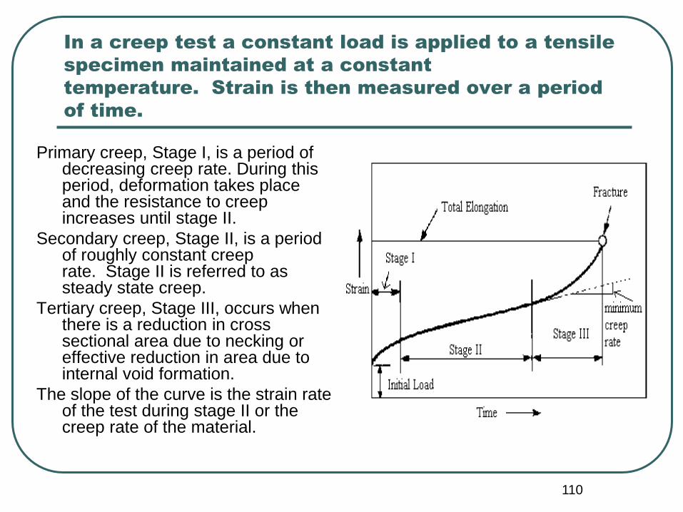
In a creep test a constant load is applied to a tensile
specimen maintained at a constant
temperature. Strain is then measured over a period
of time.
Primary creep, Stage I, is a period of decreasing creep rate. During this period, deformation takes place and the resistance to creep increases until stage II.
Secondary creep, Stage II, is a period of roughly constant creep rate. Stage II is referred to as steady state creep.
Tertiary creep, Stage III, occurs when there is a reduction in cross sectional area due to necking or effective reduction in area due to internal void formation.
The slope of the curve is the strain rate of the test during stage II or the creep rate of the material.

111
If a specimen undergoing creep is unloaded, some of
the strain is recovered, but an appreciable plastic
strain has become permanent, its amount
depending on the material and test conditions.
Change in
length

112
Stress Relaxation
The phenomenon of gradual decrease in
stress with time under a given sustained
strain is called stress relaxation.
The specimen is first subjected to a fixed
strain at an initial stress and the load
required to maintain the strain is
observed progressively by time.

113
Creep Test for Metals-1
Creep tests at high temperatures appear to be the only satisfactory guide to the performance of metals for high temperature service.
Creep tests are inherently long-time tests, but the test periods may nevertheless be short in comparison with periods of high temperature service in actual structures, so that extrapolation of creep-test data must be made with judgment.
Four variables are involved in a creep test for metals: stress, strain, time and temperature. The test may be conducted on individual specimens at each of several loads and several temperatures.

114
Creep Test for Metals-2
The determination of creep characteristics of metals
at high temperatures requires the use of three
pieces of major equipment:
(1) an electric furnace with suitable temperature-
control,
(2) an extensometer,
(3) a loading device.
Temperature measurements are made with
thermocouples.

115
Creep Test for Metals-3

116
Creep Tests for Concrete-1
Two similar test methods for determining
the creep of concrete are;
ASTM C512- Standard Test Method for
Creep of Concrete in Compression.
TS 3454 Test Method for Determining
the Creep of Concrete in Compression.

117
Creep Tests for Concrete-2
Creep of cylindrical concrete specimens
having Dmax< 50mm is determined under
constant compressive load.
Creep test specimens were loaded until
40% of their compressive strength
(compressive strength is determined on
identical specimens from the same batch).

118
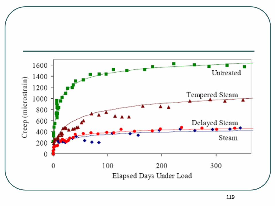
Creep Tests for Concrete-3
Strain values are recorded just before and
after loading, 2 hours and 6 hours later,
respectively. Following records were
made everyday up to one week, every
week up to one month and every month
up to one year.
At the end of the test period, creep-log t
diagram is plotted.
119