chapter 7 metals identification section … · and phosphorous.other elements are also present, but...
TRANSCRIPT

TC 9-237
CHAPTER 7METALS IDENTIFICATION
Section I. CHARACTERISTICS
7-1. GENERAL
Most of the metals and alloys used in Army materiel can be welded by one or more ofthe processes described in this manual. This section describes the characteristicsof metals and theirwelding operations.
7-2. PROPERTIES OF
a. Definitions.
(1) Ferrous
alloys, with particular reference to their significance in
METALS
All metals fall within two categories, ferrous or nonferrous.
metals are metals that contain iron. Ferrous metals appear inthe form of cast iron, carbon steel, and tool steel. The various alloys of-iron,after undergoing cetain processes, are pig iron, gray cast iron, white iron, whitecast iron, malleable cast iron, wrought iron, alloy steel, and carbon steel. Allthese types of iron are mixtures of iron and carbon, manganese, sulfur, silicon,and phosphorous. Other elements are also present, but in amounts that do not appre-ciably affect the characteristics of the metal.
(2) Nonferrous metals are those which do not contain iron. Aluminum, cop-per, magnesium, and titanium alloys are among those metals which belong to thisgroup .
b. Physical Proper t i e s . Many of the physical properties of metals determine ifand how they can be welded and how they will perform in service. Physical proper-ties of various metals are shown in table 7-1, p 7-2.
7-1


TC 9-237
(1) Color. Color relates to the quality of light reflected from the metal.
(2) Mass or density. Mass or density relates to mass with respect to vol-ume. Commonly known as specific gravity, this property is the ratio of the mass ofa given volume of the metal to the mass of the same volume of water at a specifiedtemperature, usually 39
0F (4 0C ) . For example, the ratio of weight of one cubicfoot of water to one cubic foot of cast iron is the specific gravity of cast iron.This property is measured by grams per cubic millimeter or centimeter in the metricsystem.
(3) Melting point. The melting point of a metal is important with regardto welding. A metal’s fusibility is related to its melting point, the temperatureat which the metal changes from a solid to a molten state. Pure substances have asharp melting point and pass from a solid state to a liquid without a change intemperature. During this process, however, there is an absorption of heat duringmelting and a liberation of heat during freezing. The absorption or release ofthermal energy when a substance changes state is called its latent heat. Mercuryis the only common metal that is in its molten state at normal room temperature.Metals having loW melting temperatures can be welded with lower temperature heatsources. The soldering and brazing processes utilize low-temperature metals tojoin metals having higher melting temperatures.
(4) Boiling point. Boiling point is also an important factor in welding.The boiling point is the temperature at which the metal changes from the liquidstate to the vapor state. Some metals, when exposed to the heat of an arc, willvaporize.
(5) Conductivity. Thermal and electrical conductivity relate to the met-al’s ability to conduct or transfer heat and electricity. Thermal conductivity,the ability of a metal to transmit heat throughout its mass, is of vital importancein welding, since one metal may transmit heat from the welding area much more quick-ly than another. The thermal conductivity of a metal indicates the need for pre-heating and the size of heat source required. Thermal conductivity is usuallyrelated to copper. Copper has the highest thermal conductivity of the common met-als, exceeded only by silver. Aluminum has approximately half the thermal conduc-tivity of copper, and steels have abut one-tenth the conductivity of copper.Thermal conductivity is measured in calories per square centimeter per second perdegree Celsius. Electrical conductivity is the capacity of metal to conduct anelectric current. A measure of electrical conductivity is provided by the abilityof a metal to conduct the passage of electrical current. Its opposite is resistivi-ty, which is measured in micro-ohms per cubic centimeter at a standardize tempera-ture, usually 20 0C . Electrical conductivity is usually considered as a percentageand is related to copper or silver. Temperature bears an important part in thisproperty. As temperature of a metal increases, its conductivity decreases. Thisproperty is particularly important to resistance welding and to electrical circuits.
7-3

TC 9-237
7-2. PROPERTIES OF METALS (cont)
(6) Coefficient of linear thermal expansion. With few exceptions, solidsexpand when they are heated and contract when they are cooled. The coefficient oflinear thermal expansion is a measure of the linear increase per unit length basedon the change in temperature of the metal. Expansion is the increase on the dimen-sion of a metal caused by heat. The expansion of a metal in a longitudinal direc-tion is known as the linear expansion. The coefficient of linear expansion isexpressed as the linear expansion per unit length for one degree of temperature in-crease. When metals increase in size, they increase not only in length but also inbreadth and thickness. This is called volumetric expansion. The coefficient oflinear and volumetric expansion varies over a wide range for different metals.Aluminum has the greatest coefficient of expansion, expanding almost twice as muchas steel for the same temperaturespect to warpage, wapage controllar metals.
(7) Corrosion resistance.or wearing away by air, moisture,
change. This is important for welding with re-and fixturing, and for welding together dissimi-
Corrosion resistance is the resistance to eatingor other agents.
c. Mechanical Properties. The mechanical properties of metals determine therange of usefulness of the metal and establish the service that can be expected.Mechanical properties are also used to help specify and identify the metals. Theyare important in welding because the weld must provide the same mechanical proper-ties as the base metals being joined. The adequacy of a weld depends on whether ornot it provides properties equal to or exceeding those of the metals being joined.The most common mechanical properties considered are strength, hardness, ductility,and impact resistance. Mechanical properties of various metals are shown in table7-2.
7-4

TC 9-237
(1) Tensile strength. Tensile strength is defined as the maximum load intension a material will withstand before fracturing, or the ability of a materialto resist being pulled apart by opposing forces. Also known as ultimate strength,it is the maximum strength developed in a metal in a tension test. (The tensiontest is a method for determing the behavior of a metal under an actual stretchloading. This test provides the elastic limit , elongation, yield point, yieldstrength, tensile strength, and the reduction in area.) The tensile strength isthe value most commonly given for the strength of a material and is given in poundsper square inch (psi) (kiloPascals (kPa)). The tensile strength is the number ofpounds of force required1.00 in. (25.4 mm) thick
to pull apart a bar of material 1.0 in. (25.4 mm)(fig. 7-1).
wide and
(2) Shear strength. Shear strength is the ability of a material to resistbeing fractured by opposing forces acting of a straight line but not in the sameplane, or the ability of a metal to resist being fractured by opposing forces notacting in a straight line (fig. 7-2).
7-5

TC 9-237
7-2. PROPERTIES OF METALS (cont)
(3) Fatigue strength. Fatigue strength is the maximum load a material canwithstand without failure during a large number of reversals of load. For example,a rotating shaft which supports a weight has tensile forces on the top portion ofthe shaft and compressive forces on the bottom. As the shaft is rotated, there isa repeated cyclic change in tensile and compressive strength. Fatigue strengthvalues are used in the design of aircraft wings and other structures subject torapidly fluctuating loads. Fatigue strength is influenced by microstructure, sur-face condition, corrosive environment, and cold work.
(4) Compressive strength. Compressive strength is the maximum load incompression a material will withstand before a predetermined amount of deformation,or the ability of a material(fig. 7-3). The compressivethan their tensile strength.
to withstand pressures acting in a given planestrength of both cast iron and concrete are greaterFor most materials, the reverse is true.
(5) E las t ic i ty . Elasticity is the ability of metal to return to its origi-nal size, shape, and dimensions after being deformed, stretched, or pulled out ofshape. The elastic limit is the point at which permanent damage starts. The yieldpoint is the point at which definite damage occurs with little or no increase inload. The yield strength is the number of pounnds per square inch (kiloPascals) ittakes to produce damage or deformation to the yield point.
(6) Modulus of elasticity. The modulus of elasticity is the ratio of theinternal stress to the strain produced.
(7) Duct i l i ty . The ductility of a metal is that property which allows itto be stretched or otherwise changed in shape without breaking, and to retain thechanged shape after the load has been ramoved. It is the ability of a material,such as copper, to be drawn or stretched permanently without fracture. The ductili-ty of a metal can be determined by the tensile test by determining the percentageof elongation. The lack of ductility is brittleness or the lack of showing anypermanent damage before the metal cracks or breaks (such as with cast iron).
(8) P las t ic i ty . Plasticity is the ability of a metal to be deformed exten-sively without rupture. Plasticity is similar to ductility.
(9) Malleabil i ty. Malleability is another form of plasticity, and is theability of a material to deform permanently under compression without rupture. Itis this property which allows the hammering and rolling of metals into thinsheets. Gold, silver, tin, and lead are examples of metals exhibiting high mallea-b i l i t y . Gold has exceptional malleability and can be rolled into sheets thinenough to transmit light.
7-6

TC 9-237
(10) Reduction of area. This is a measure of ductility and is obtainedfrom the tensile test by measuring the original cross-sectional area of a specimento a cross-sectional area after failure.
(11) Brit t leness. Brittleness is the property opposite ofducti l i ty. A brittle metal is one than cannot be visibly deformedone that lacks plasticity.
plasticity orpermanently, or
(12) Toughness. Toughness is a combination of high strength and mediumducti l i ty. It is the ability of a material or metal to resist fracture, plus theability to resist failure after the damage has begun. A tough metal, such as coldchisel, is one that can withstand considerable stress, slowly or suddenly applied,and which will deform before failure. Toughness is the ability of a material toresist the start of permanent distortion plus the ability to resist shock or absorbenergy.
(13) Machinability and weldability. The property of machinability andweldability is the ease or difficulty with which a material can be machined orwelded.
(14) Abrasion resistance. Abrasion resistance is the resistance to wearingby friction.
(15) I mpact resistance. Resistance of a metal to impacts is evaluated interms of impact strength. A metal may possess satisfactory ductility under staticloads, but may fail under dynamic loads or impact. The impact strength of a metalis determined by measuring the energy absorbed in the fracture.
(16) Hardness. Hardness is the ability of a metal to resist penetrationand wear by another metal or material. It takes a combination of hardness andtoughness to withstand heavy pounding. The hardness of a metal limits the easewith which it can be machined, since toughness decreases as hardness increases.Table 7–3, p 7-8, illustrates hardness of various metals.
(a) Brinell hardness test. In this test, a hardened steel ball ispressed slowly by a known force against the surface of the metal to be tested. Thediameter of the dent in the surface is then measured, and the Brinell hardnessnumber (bhn) is determined by from standard tables (table 7-3, p 7-8).
(b) Rockwell hardness test. This test is based upon the differencebetween the depth to which a test point is driven into a metal by a light load andthe depth to which it is driven in by a heavy load. The light load is first ap-plied and then, without moving the piece, the heavy load is applied. The hardnessnumber is automatically indicated on a dial. The letter designations on the Rock-well scale, such as B and C, indicate the type of penetrator used and the amount ofheavy load (table 7-3, p 7-8). The same light load is always used.
(c) Scleroscope hardness test. This test measures hardness by lettinga diamond-tipped hammer fall by its own weight from a fixed height and rebound fromthe surface; the rebound is measured on a scale. It is used on smooth surfaceswhere dents are not desired.
7-7

TC 9-237

TC 9-237
7-3. CATEGORIES OF METALS (cont)
a. General. It is necessary to know the composition of the metal being weldedin order to produce a successful weld. Welders and metal workers must be able toidentify various metal products so that proper work methods may be applied. ForArmy equipment, drawings (MWOs) should be available. They must be examined inorder to determine the metal to be used and its heat treatment, if required. AfterSome practice, the welder will learn that certain parts of machines or equipmentare always cast iron, other parts are usually forgings, and so on.
b. Tests. There are seven tests that can be performed in the shop to identifymetals. Six o f t h e d i f f e r e n t t e s t s a r e summarized in table 7-4, p 7-10. Theseshould be supplemented by tables 7-1 and 7-2 (p 7-2 and 7-4) which present physicaland mechanical properties of metal, and table 7-3, which presents hardness data.These tests are as follows:
7-9


TC 9-237
(1) A ppearance test. The appearance test includes such things as color andappearance of machined as well as unmachined surfaces. Form and shape give defi-nite clues as to the identity of the metal. The shape can be descriptive; forexample, shape includes such things as cast engine blocks, automobile bumpers,reinforcing rods, I beams or angle irons, pipes, and pipe fittings. Form should beconsidered and may show how the part was rode, such as a casting with its obvioussurface appearance and parting mold lines, or hot rolled wrought material, extrudedor cold rolled with a smooth surface. For example, pipe can be cast, in which caseit would be cast iron, or wrought, which would normally be steel. Color provides avery strong clue in metal identification. It can distinguish many metals such ascopper, brass, aluminum, magnesium, and the precious metals. If metals are oxi-dized, the oxidation can be scraped off to determine the color of the unoxidizedmetal. This helps to identify lead, magnesium, and even copper. The oxidation onsteel, or rust, is usually a clue that can be used to separate plain carbon steelsfrom the corrosion-resisting steels.
(2) Fracture test. Some metal can be quickly identified by looking at thesurface of the broken part or by studying the chips produced with a hammer andchisel. The surface will show the color of the base metal without oxidation. Thiswill be true of copper, lead, and magnesium. In other cases, the coarseness orroughness of the broken surface is an indication of its structure. The ease ofbreaking the part is also an indication of its ductility of lack of ductility. Ifthe piece bends easily without breaking, it is one of the more ductile metals. Ifit breaks easily with little or no bending, it is one of the brittle metals.
(3) Spark test. The spark test is a method of classifying steels and ironaccording to their composition by observing the sparks formed when the metal isheld against a high speed grinding wheel. This test does not replace chemicalanalysis, but is a very convenient and fast method of sorting mixed steels whosespark characteristics are known. When held lightly against a grinding wheel, thedifferent kinds of iron and steel produce sparks that vary in length, shape, andcolor. The grinding wheel should be run to give a surface speed of at least 5000ft (1525 m) per minute to get a good spark stream. Grinding wheels should be hardenough to wear for a reasonable length of time, yet soft enough to keep a free-cut-ting edge. Spark testing should be done in subdued light, since the color of thespark is important. In all cases, it is best to use standard samples of metal forthe purpose of comparing their sparks with that of the test sample.
(a) Spark testing is not of much use on nonferrous metals such as cop-pers, aluminums, and nickel-base alloys, since they do not exhibit spark streams ofany significance. However, this is one way to separate ferrous and nonferrousmetals.
7-11

TC 9-237
7-3. CATEGORIES OF METALS (cont)
(b) The spark resulting from the test should be directed downward andstudied. The color, shape, length, and activity of the sparks relate to character-istics of the material being tested. The spark stream has specific items which Car.be identified. The straight lines are called carrier lines. They are usuallysolid and continuous. At the end of the carrier line, they may divide into threeshort lines, or forks. If the spark stream divides into more lines at the end, itis called a sprig. Sprigs also occur at different places along the carrier line.These are called either star or fan bursts. In some cases, the carrier line willenlarge slightly for a very short length, continue, and perhaps enlarge again for ashort length. When these heavier portions occur at the end of the carrier line,they are called spear points or buds. High sulfur creates these thicker spots incarrier lines and the spearheads. Cast irons have extremely short streams, whereaslow–carbon steels and most alloy steels have relatively long streams. Steels usual-ly have white to yellow color sparks, while cast irons are reddish to straw yel-low. A 0.15 percent carbon steel shins sparks in long streaks with some tendencyto burst with a sparkler effect; a carbon tool steel exhibits pronounced bursting;and a steel with 1.00 percent cabon shows brilliant and minute explosions or spar-klers. As the carbon content increases, the intensity of bursting increases.
(c) One big advantage of this test is that it can be applied to metal in,all stages, bar stock in racks, machined forgings or finished parts. The sparktest is best conducted by holding the steel stationary and touching a high speedportable grinder to the specimen with sufficient pressure to throw a horizontalspark stream about 12.00 in. (30.48 cm) long and at right angles to the line ofvision. Wheel pressure against the work is important r because increasing pressurewill raise the temperature of the spark stream and give the appearance of highercarbon content. The sparks near and around the wheel, the middle of the sparkstream, and the reaction of incandescent particles at the end of the spark streamshould be observed. Sparks produced by various metals are shown in figure 7-4.
7-12


TC 9-237
7-3. CATEGORIES OF METALS (cont)
CAUTIONThe torch test should be used with discretion, as it may damage thepart being tested. Additionally, magnesium may ignite when heated inthe open atmosphere.
(4) Torch test. With the oxyacetylene torch, the welder can identify vari-ous metals by studying how fast the metal melts and how the puddle of molten metaland slag looks, as well as color changes during heating. When a sharp corner of awhite metal part is heated, the rate of melting can be an indication of its identi-ty. If the material is aluminum, it will not melt until sufficient heat has beenused because its high conductivity. If the part is zinc, the sharp corner willmelt quickly, since zinc is not a good conductor. In the case of copper, if thesharp comer melts, it is normally deoxidized copper. If it does not melt untilmuch heat has been applied, it is electrolytic copper. Copper alloys, if composedof lead, will boil. To distinguish aluminum from magnesium, apply the torch tofi l ings. Magnesium will burn with a sparkling white flame. Steel will show charac-teristic colors before melting.
(5) Magnetic test. The magnetic test can be quickly performed using asmall pocket magnet. With experience, it is possible to judge a strongly magneticmaterial from a slightly magnetic material. The nonmagnetic materials are easilyrecognized. Strongly magnetic materials include the carbon and low-alloy steels,iron alloys, pure nickel, and martensitic stainless steels. A slightly magneticreaction is obtained from Monel and high-nickel alloys and the stainless steel ofthe 18 chrome 8 nickel type when cold worked, such as in a seamless tube. Nonmag-netic materials include copper-base alloys, aluminum-base alloys, zinc-base alloys,annealed 18 chrome 8 nickel stainless, the magnesium, and the precious metals.
(6) Chisel test. The chip test or chisel test may also be used to identifymetals. The only tools required are a banner and a cold chisel. Use the coldchisel to hammer on the edge or corner of the material being examined. The ease ofproducing a chip is an indication of the hardness of the metal. If the chip iscontinuous, it is indicative of a ductile metal, whereas if chips break apart, itindicates a brittle material. On such materials as aluminum, mild steel and mallea-ble iron, the chips are continuous. They are easily chipped and the chips do nottend to break apart. The chips for gray cast iron are so brittle that they becomesmall, broken fragments. On high-carbon steel, the chips are hard to obtain be-cause of the hardness of the material, but can be continuous.
(7) Hardness test. Refer to table 7-3, p 7-8, for hardness values of thevarious metals, and to p 7-7 for information on the three hardness tests that arecommonly used. A less precise hardness test is the file test. A summary of thereaction to filing, the approximate Brinell hardness, and the possible type ofsteel is shown in table 7-6. A sharp mill file must be used. It is assumed thatthe part is steel and the file test will help identify the type of steel.
7-14

TC 9-237
(8). Chemical test. There are numerous chemical test than can be made in the shop to identify some material. Monel can be distinguished form Inconel byone drop of nitric acid applied to the surface. It will turn blue-green on Monel,but will show no reaction on Inconel. A few drops of a 45 percent phosphoric acid will bubble on low-chomium stainless steels. Magnesium can be distinguished fromaluminum using silver nitrate, which will leave a black deposit on magnesium, butnot on aluminum. These tests can become complicated, and for this reason are notdetailed further here.
c. Color Code for Marking Steel Bars. The Bureau of Standards of the UnitedStates Department of Commerce has a color code for making steel bars. The colormarkings provided in the code may be applied by painting the ends of bars. Solidcolors usually mean carbon steel, while twin colors designate alloy and free-cut-ting steel.
d. Ferrous Metal . The basic substance used to make both steel and cast iron(gray and malleable) is iron. It is used in the form of pig iron. Iron is pro-duced form iron ore that occurs chiefly in nature as an oxide, the two most impor-tant oxides being hematite and magetite. Iron ore is reduced to pig iron in a blast furnace, and the impurtities are removed in the form of slag (fig. 7-5, p7-16). Raw materials charged into the furnace include iron ore, coke, and lime-stone. The pig iron produced is udes to manufacture steel or cast i ron.
Plain carbon steel consists of iron and carbon. Carbon is the hardening element. Tougher alloy steel contains other elements such as chromium, nickel, and molybde- num. Cast iron is nothing more than basic carbon steel with more carbon added, along with silicon. The carbon content range for steel is 0.03 to 1.7 percent, and 4.5 percent for cast iron.
7 - 1 5

TC 9-237
7-3. CATEGORIES OF METALS (cont)
Steel is produced in a variety of melting furnaces, such as open-hearth, Bessemerconverter, crucible, electric-arc, and induction. Most carbon steel is made inopen-hearth furnaces, while alloy steel is melted in electric-arc and inductionfurnaces. Raw materials charged into the furnace include mixtures of iron ore, pigiron, limestone, and scrap. After melting has been completed, the steel is tappedfrom the furnace into a ladle and then poured into ingots or patterned molds. Theingots are used to make large rectangular bars, which are reduced further by roll-ing operations. The molds are used for castings of any design.
7-16

TC 9-237
Cast iron is produced by melting a charge of pig iron, limestone, and coke in acupola furnace. It is then poured into sand or alloy steel molds. When makinggray cast iron castings, the molten metal in the mold is allowed to become solidand cool to room temperature in open air. Malleable cast iron, on the other hand,is made from white cast iron, which is similar in content to gray cast iron exceptthat malleable iron contains less carbon and silicon. White cast iron is annealedfor more than 150 hours at temperatures ranging from 1500 to 1700 OF (815 to927 0C). The result is a product called malleable cast iron. The desirable proper-ties of cast iron are less than those of carbon steel because of the difference inchemical makeup and structure. The carbon present in hardened steel is in solidsolution, while cast iron contains free carbon known as graphite. In gray castiron, the graphite is in flake form, while in malleable cast iron the graphite isin nodular (rounded) form. This also accounts for the higher mechanical propertiesof malleable cast iron as compared with gray cast iron.
Iron ore is smelted with coke and limestone in a blast furnace to remove the oxygen(the process of reduction) and earth foreign matter from it. Limestone is used tocombined with the earth matter to form a liquid slag. Coke is used to supply thecarbon needed for the reduction and carburization of the ore. The iron ore, lime-stone, and coke are charged into the top of the furnace. Rapid combustion with ablast of preheated air into the smelter causes a chemical reaction, during whichthe oxygen is removed from the iron. The iron melts, and the molten slag consist-ing of limestone flux and ash from the coke, together with compounds formed byreaction of the flux with substances present in the ore, floats on the heavier ironliquid. Each material is then drawn off separately (fig. 7-6, p 7-18).
All forms of cast iron, steel, and wrought iron consist of a mixture of iron, car-bon, and other elements in small amounts. Whether the metal is cast iron or steeldepends entirely upon the amount of carbon in it. Table 7-7 shows this principle.
Cast iron differs from steel mainly because its excess of carbon (more than 1.7percent) is distributed throughout as flakes of graphite, causing most of the re-maining carbon to separate. These particles of graphite form the paths throughwhich failures occur, and are the reason why cast iron is brittle. By carefullycontrolling the silicon content and the rate of cooling, it is possible to causeany definite amount of the carbon to separate as graphite or to remain combined.Thus, white, gray, and malleable cast iron are all produced from a similar base.
7-17


TC 9-237
(1) Wrought iron.
(a) General. Wrought iron is almost pure iron. It is made from pigiron in a puddling Furnace and has a carbon content of less than 0.08 percent.Carbon and other elements present in pig iron are taken out, leaving almost pureiron. In the process of manufacture, some slag is mixed with iron to form a fi-brous structure in which long stringers of slag, running lengthwise, are mixed withlong threads of iron. Because of the presence of slag, wrought iron resists corro-sion and oxidation, which cause
(b) Uses. Wroughtimplements, nails, barbed wire,
(c) Capabil i t ies.plated, and is easily formed.
rusting .
iron is used for porch railings, fencing, farmchains, modern household furniture, and decorations.
Wrought iron can be gas and arc welded, machined,
(d) Limitations. Wrought iron has loW hardness and low fatiguestrength.
(e) Propert ies. Wrought iron has Brinell hardness number of 105;tensile strength of 35,000 psi; specific gravity of 7.7; melting point of 2750 0F(151O 0C); and is ductile and corrosion resistant.
(f) Appearance test. The appearance of wrought iron is the same asthat of rolled, low-carbon steel.
(g) Fracture test. Wrought iron has a fibrous structure due tothreads of slag. As a result, it can be split in the direction in which the fibersrun. The metal is soft and easily cut with a chisel, and is quite ductile. Whennicked and bent, it acts like rolled steel. However, the break is very jagged dueto its fibrous structure. Wrought iron cannot be hardened.
(h) S p a rk test. When wrought iron is ground, straw-colored sparksform near the grinding wheel, and change to white, forked sparklers near the end ofthe stream.
(i) Torch test . Wrought iron melts quietly without sparking. It hasa peculiar slag coating with white lines that are oily or greasy in appearance.
(2) Cast iron (gray, white, and malleable).
(a) General . Cast iron is a manmade alloy of iron, carbon, and sili-con. A portion of the carbon exists as free carbon or graphite. Total carboncontent is between 1.7 and 4.5 percent.
(b) Uses. Cast iron is used for water pipes, machine tool castings,transmission housing, engine blocks, pistons, stove castings, etc.
(c) Capabi l i t i e s . Cast iron may be brazed or bronze welded, gas andarc welded, hardened, or machined.
(d) Limitations. Cast iron must be preheated prior to welding. Itcannot be worked cold.
7-19

TC 9-237
7-3. CATEGORIES OF METALS (cont)
(e) Propert ies. Cast iron has a Brinell hardness number of 150 to 220(no alloys) and 300 to 600 (alloyed); tensile strength of 25,000 to 50,000 psi(172,375 to 344,750 kPa) (no alloys) and 50,000 to 100,OOO psi (344,750 to 689,500kPa) (alloyed); specific gravity of 7.6; high compressive strength that is fourtimes its tensile strength; high rigidity; good wear resistance; and fair corrosionresistance.
(f) Gray cast iron. If the molten pig iron is permitted to cool slow-ly, the chemical compund of iron and carbon breaks up to a certain extent. Muchof the carbon separates as tiny flakes of graphite scattered throughout the metal.This graphite-like carbon, as distinguish from combined carbon, causes the grayappearance of the fracture, which characterizes ordinary gray cast iron. Sincegraphite is an excellent lubricant , and the metal is shot throughout with tiny,flaky cleavages, gray cast iron is easy to machine but cannot withstand a heavyshock. Gray cast iron consists of 90 to 94 percent metallic iron with a mixture ofcarbon, manganese, phosphorus, sulfur, and silicon. Special high-strength gradesof this metal also contain 0.75 to 1.50 percent nickel and 0.25 to 0.50 percentchromium or 0.25 to 1.25 percent molybdenum. Commercial gray iron has 2.50 to 4.50percent carbon. About 1 percent of the carbon is combined with the iron, whileabout 2.75 percent remains in the free or graphitic state. In making gray castiron, the silicon content is usually increased, since this allows the formation ofgraphitic carbon. The combined carbon (iron carbide), which is a small percentageof the total carbon present in cast iron, is known as cementite. In general, themore free carbon (graphitic carbn) present in cast iron, the lower the combinedcarbon content and the softer the iron.
1. Appe arance test. The unmachined surface of gray cast ironcastings is a very dull gray in color and may be somewhat roughened by the sandmold used in casting the part. Cast iron castings are rarely machined all over.Unmachined castings may be ground in places to remove rough edges.
2. Fracture test. Nick a corner all around with a chisel orhacksaw and strike the corner with a sharp blow of the hammer. The dark gray colorof the broken surface is caused by fine black specks of carbon present in the formof graphite. Cast iron breaks short when fractured. Small, brittle chips madewith a chisel break off as soon as they are formed.
3. S park test. A small volume of dull-red sparks that follow astraight line close to the wheel are given off when this metal is spark tested.These break up into many fine, repeated spurts that change to a straw color.
4. Torch test. The torch test results in a puddle of moltenmetal that is quiet and has a jelly like consistency. When the torch flame israised, the depression in the surface of the molts-puddle disappears instantly. A heavy, tough film forms on the surface as it melts. The molten puddle takes timeto harden and gives off no sparks.
(g) White cast iron. When gray cast iron is heated to the moltenstate, the carbon completely dissolves in the iron, probably combining chemicallywith it. If this molten metal is cooled quickly, the two elements remain in thecombined state, and white cast iron is formed. The carbon in this type of iron
7-20

TC 9-237
measures above 2.5 to 4.5 percent by weight, and is referred to as combined car-bon. White cast iron is very hard and brittle, often impossible to machine, andhas a silvery white fracture.
(h) Malleable cast iron. Malleable cast iron is made by heating whitecast iron froman 1400 to 1700 0F (760 and 927 0C) for abut 150 hours in boxes con-taining hematite ore or iron scale. This heating causes a part of the combinedcarbon to change into the free or uncombined state. This free carbon separates ina different way from carbon in gray cast iron and is called temper carbon. Itexists in the form of small, rounded particles of carbon which give malleable ironcastings the ability to bend before breaking and to withstand shock better thangray cast iron. The castings have properties more like those of pure iron: highstrength, ductility, toughness, and ability to resist shock. Malleable cast ironcan be welded and brazed. Any welded part should be annealed after welding.
1. Appearance test. The surface of malleable cast iron is verymuch like gray cast iron, but is generally free from sand. It is dull gray andsomewhat lighter in color than gray cast iron.
2. Fracture test. When malleable cast iron is fractured, thecentral portion of the broken surface is dark gray with a bright, steel-like bandat the edges. The appearance of the fracture may best be described as a pictureframe. When of good quality, malleable cast iron is much tougher than other castiron and does not break short when nicked.
3 . S p a rk test. When malleable cast iron is ground, the outer,bright layer gives off bright sparks like steel. As the interior is reached, thesparks quickly change to a dull-red color near the wheel. These sparks from theinterior section are very much like those of cast iron; however, they are somewhatlonger and are present in large volume.
4. Torch test. Molten malleable cast iron boils under the torchflame. After the-flame has been withdrawn, the surface will be full of blowholes.When fractured, the melted parts are very hard and brittle, having the appearanceof white cast iron (they have been changed to white or chilled iron by melting andfairly rapid cooling). The outside, bright, steel-like band gives off sparks, butthe center does not.
(3) S t e e l .
(a) General. A form of iron, steel contains less carbon than castiron, but considerably more than wrought iron. The carbon content is from 0.03 to1.7 percent. Basic carbon steels are alloyed with other elements, such as chromiumand nickel, to increase certain physical properties of the metal.
(b) Uses. Steel is used to make nails, rivets, gears, structuralsteel, roles, desks, hoods, fenders, chisels, hammers, etc.
(c) Capabilities. Steel can be machined, welded, and forged, all tovarying degrees, depending on the type of steel.
(d) Limitations. Highly alloyed steel is difficult to produce.
7-21

TC 9-237
7-3. CATEGORIES OF METALS (cont)
(e) Propert i e s . Steel has tensile strength of 45,000 psi (310,275kPa) for low-carbon steel, 80,000 psi (551,600 kPa) for medium-carbon steel, 99,000psi (692,605 kPa) for high-carbon steel, and 150,000 psi (1,034,250 kPa) for al-loyed steel; and a melting point of 2800 0F (1538 0C).
(f) Low-carbon steel (carbon content up to 0.30 percent. This steelis soft and ductile, and can be rolled, punched, sheared, and worked when eitherhot or cold. It is easily machined and can readily be welded by all methods. Itdoes not harden to any great amount; however, it can easily be case hardened.
1. Appearance test. The appearance of the steel depends upon themethod of preparation rather than upon composition. Cast steel has a relativelyrough, dark-gray surface, except where it has been machined. Rolled steel has finesurface lines running in one direction. Forged steel is usually recognizable byits shape, hammer marks, or fins.
2. Fracture test. When low-carbon steel is fractured, the coloris bright crystalline gray. It is tough to chip or nick. Low carbon steel,wrought iron, and steel castings cannot be hardened.
3. Spark test. The steel gives off sparksstreaks, brighter than cast iron, that show some tendency toforked sparklers.
4. Torch test. The steel gives off sparksens almost instantly.
in long yellow-orangeburst into white,
when melted, and hard-
(g) Medium-carbon steel (carbon content ranging from 0.30 to 0.50percent). This steel may be heat-treated after fabrication. It is used for gener-al machining and forging of parts that require surface hardness and strength. Itis made in bar form in the cold-rolled or the normalized and annealed condition.During welding, the weld zone will become hardened if cooled rapidly and must bestress-relieved after welding.
(h) High-carbon steel (carbon content ranging from 0.50 to 0.90 per-cent ) . This steel is used for the manufacture of drills, taps, dies, springs, andother machine tools and hand tools that are heat treated after fabrication to devel-op the hard structure necessary to withstand high shear stress and wear. It ismanufactured in bar, sheet, and wire forms, and in the annealed or normalized condi-tion in order to be suitable for machining before heat treatment. This steel isdifficult to weld because of the hardening effect of heat at the welded joint.
1. Appearance test. The unfinished surface of high-carbon steelis dark gray and similar to other steel. It is more expensive, and is usuallyworked to produce a smooth surface finish.
2. Fracture test. High-carbon steel usually produces a veryfine-grained fracture, whiter than low-carbon steel. Tool steel is harder and morebrittle than plate steel or other low-carbon material. High-carbon steel can behardened by heating to a good red and quenching in water.
7-22

3.bright yellow-orange
4.
Spark test. High-carbon steel gives off a largesparks.
TC 9-237
volume of
Torch test. Molten high-carbon steel is brighter than low-carbon steel, and the melting surface has a porous appearance. It sparks morefreely than low-carbon (mild) steels, and the sparks are whiter. -
(i) High carbon tool steel. Tool steel (carbon content ranging from0.90 to 1.55 percent) is used in the manufacture of chisels, shear blades, cutters,large taps, wood-turning tools, blacksmith’s tools, razors, and similar parts wherehigh hardness is required to maintain a sharp cutting edge. It is difficult toweld due to the high carbon content. A spark test shows a moderately large volumeof white sparks having many fine, repeating bursts.
(4) Cast steel.
(a) General. Welding is difficult on steel castings containing over0.30 percent carbon and 0.20 percent silicon. Alloy steel castings containing nick-el, molybdenum, or both of these metalslow.
, are easily welded if the carbon content isThose containing chromium or vanadium are more difficult to weld. Since
manganese steel is nearly always used in the form of castings, it is also consid-ered with cast steel. Its high resistance to wear is its most valuable property.
(b) Appearance test. The surface of cast steel is brighter than castor malleable iron and sometimes contains small,
(c) Fracture test .crystalline gray. This steel isare tougher than malleable iron,nese steel, however, is so toughmachined.
The color of atough and doesand chips madethat is cannot
bubble-like depressions.
fracture in cast steel is brightnot break short. Steel castingswith a chisel curl up more. Manga-be cut with a chisel nor can it be
(d) Spark test. The sparks created from cast steel are much brighterthan those from cast iron. Manganese steel gives off marks that explode, throwingoff brilliant sparklers at right angles to the original-path of the spark:
(e) Torch test. When melted, cast steel sparks and hardens quickly.
(5) Steel forgings.
(a) General . Steel forgings may be of carbon or alloy steels. Alloysteel forgings are harder and more brittle than low carbon steels.
(b) Appearance test. The surface of steel forgings is smooth. Wherethe surface of drop forgings has not been finished, there will be evidence of thefin that results from the metal squeezing out between the two forging dies. Thisfin is removed by the trimming dies, but enough of the sheared surface remains foridentification. All forgings are covered with reddish brown or black scale, unlessthey have been purposely cleaned.
7-23

TC 9-237
7-3. CATEGORIES
(c)
OF METALS (cont)
Fracture test. The color of a fracture in a steel forging variesfrom bright crystalline to silky gray. Chips are tough; and when a sample isnicked, it is harder to break than cast steel and has a finer grain. Forgings maybe of low- or high-carbon steel or of alloy steel. Tool steel is harder and morebrittle than plate steel or other low-carbon material. The fracture is usuallywhiter and finer grained. Tool steel can be hardened by heating to a good red andthen quenching in water. Low-carbon steel, wrought iron, and steel castings cannotbe usefully hardened.
(d) S p a rk test. The sparks given off are long, yellow-orange stream-ers and are typical steel sparks. Sparks from high-carbon steel (machinery andtool steel) are much brighter than those from low-carbon steel.
(e) Torch test. Steel forgings spark when melted, and the sparksincrease in number and brightness as the carbon content becomes greater.
(6) Alloy steel.
(a) General. Alloy steel is frequently recognizable by its use.There are many varieties of alloy steel used in the manufacture of Army equipment.They have greater strength and durability than carbon steel, and a given strengthis secured with less material weight. Manganese steel is a special alloy steelthat is always used in the cast condition (see cast steel, p 7-23).
Nickel, Chromiumr vanadium, tungsten, molybdenum, and silicon are the most commonelements used in alloy steel.
1. Chromium is used as an alloying element in carbon steels toincrease hardenability, corrosion resistance, and shock resistance. It impartshigh strength with little loss in ductility.
2. Nickel increases the toughness, strength, and ductility ofsteels, and lowers the hardening temperatures so than an oil quench, rather than awater quench, is used for hardening.
3. Manganese is used in steel to produce greater toughness, wearresistance, easier hot rolling, and forging. An increase in manganese contentdecreases the weldability of steel.
4. Molybdenum increases hardenability, which is the depth ofhardening possible through heat treatment. The impact fatigue property of thesteel is improved with up to 0.60 percent molybdenum. Above 0.60 percent molybde-num, the impact fatigue property is impaired. Wear resistance is improved withmolybdenum content above 0.75 percent. Molybdenum is sometimes combined with chro-mium, tungsten, or vanadium to obtain desired properties.
5. Titanium and columbium (niobium) are used as additional alloy-ing agents in low-carbon content, corrosion resistant steels. They support resis-tance to intergranular corrosion after the metal is subjected to high temperaturesfor a prolonged time period.
7-24

6. Turgsten,fine, dense grain-when used in
as ansmall
TC 9-237
alloying element in tool steel, produces aquantities. When used in larger quantities,
from 17 to 20 percent, and in combination with other alloys, it produces a steelthat retains its hardness at high temperatures.
7. Vanadium is used to help control grain size. It tends toincrease hardenability and causes marked secondary hardness, yet resists temper-ing. It is also added to steel during manufacture to remove oxygen.
8. Silicon is added to steel to obtain greater hardenability and—corrosion resistance, and is often used with manganese to obtain a strong, toughsteel . High speed tool steels are usually special alloy compositions designed forcutttig tools. The carbon content ranges from 0.70 to 0.80 percent. They aredifficult to weld except by the furnace induction method.
9. High yield strength, low alloy structural steels (often re-ferred to as constructional alloy steels) are special low carbon steels containingspecific small amounts of alloying elements. These steels are quenched and tem-pered to obtain a yield strength of 90,000 to 100,000 psi (620,550 to 689,500 kPa)and a tensile strength of 100,000 to 140,000 psi (689,500 to 965,300 kPa), depend-ing upon size and shape. Structural members fabricated of these high strengthsteels may have smaller cross sectional areas than common structural steels, andstill have equal strength. In addition, these steels are more corrosion and abra-sion resistant. In a spark test, this alloy appears very similar to the low carbonsteels.
This type of steel is much tougher than low carbon steels, and shear-ing machines must have twice the capacity required for low carbon
NOTE
s teels .
(b) Apperance test . Alloy steelsteel .
(c) Fracture test . Alloy steel istimes the fracture appears velvety.
appear the same as drop-forged
usually very close grained; at
(d) Spark test. Alloy steel produces characteristic sparks both incolor and shape. some of the more common alloys used in steel and their effects onthe spark stream are as follows:
1. Chromium. Steels containing 1 to 2 percent chromium have nooutstanding features in the spark test. Chromium in large amounts shortens thespark stream length to one-half that of the same steel without chromium, but doesnot appreciably affect the stream’s brightness. Other elements shorten the streamto the same extent and also make it duller. An 18 percent chromium, 8 percentnickel stainless steel produces a spark similar to that of wrought iron, but onlyhalf as long. Steel containing 14 percent chromium and no nickel produces a short-er version of the low-carbon spark. An 18 percent chromium, 2 percent carbon steel(chromium die steel) produces a spark similar to that of carbon tool steel, butone-third as long.
7-25

TC 9-237
7-3. CATEGORIES OF METALS (cont)
2.bri l l iant l ight justel can be recognizedtoo noticeable.
Nicke l . The nickel spark has a short,before the fork. In the amounts foundonly when the carbon content is so low
sharply defined dash ofin S.A.E. steels, nick-that the bursts are not
3. High chromium-nickel alloy (stainless) steels. The sparksgiven off during a spark test are straw colored near the grinding wheel and whitenear the end of the streak. There is a medium volume of streaks having a moderatenumber of forked bursts.
4. Manganese. Steel containing this element produces a sparksimilar to a carbon steel spark. A moderate increase in manganese increases thevolume of the spark stream and the force of the bursts. Steel containing more thanthe normal amount of manganese will spark in a manner similar to high-carbon steelwith low manganese content.
5. Molybdenum. Steel containing this element produces a charac-teristic spark with a detached arrowhead similar to that of wrought iron. It canbe seen even in fairly strong carbon bursts. Molybdenum alloy steel contains nick-el, chromium, or both.
6. Molybdenum with other elements. When molybdenum and otherelements are substituted for Some of the tungsten in high-speed steel, the sparkstream turns orange. Although other elements give off a red spark, there is enoughdifference in their color to tell them from a tungsten spark.
7. Tungsten . Tungsten will inpart a dull red color to the sparkstream near the wheel. It also shortens the spark stream, decreases the size, orcompletely eliminates the carbon burst. Steel containing 10 percent tungsten caus-es short, curved, orange spear points at the end of the carrier lines. Still lowertungsten content causes small white bursts to appear at the end of the spearp i n t . Carrier lines may be anything from dull red to orange in color, dependingon the other elements present, if the tungsten content is not too high.
with a detachedfrom molybdenum
8. Vanadium. Alloy steels containing vanadium produce sparksarrowhead at the end of the carrier line similar to those arisingsteels. The spark test is not positive for vanadium steels.
9. High speed tool steels. A spark test in these steels willimpart a few long; forked sparks which are red near the wheel, and straw-colorednear the end of the spark stream.
(7) Special steel. Plate steel is used in the manufacture of built-upwelded structures such as gun carriages. In using nickel plate steel, it has beenfound that commericial grades of low-alloy structural steel of not over 0.25 percentcarbon, and several containing no nickel at all, are better suited to welding thanthose with a maximum carbon content of 0.30 percent. Armorplate, a low carbon al-loyed steel, is an example of this kind of plate. Such plate is normally used inthe “as rolled” condition. Electric arc welding with a covered electrode may re-quire(postequal
7-26
preheating of the metal, followed by a proper stress-relieving heat treatmentheating), to produce a structure in which the welded joint has propertiesto those of the plate metal.

TC 9-237
e. Nonferrous metal.
(1) Aluminum (Al).
(a) General . Aluminum is a lightweight, soft, low strength metalwhich can easily be cast, forged, machined, formed, and welded. It is suitableonly in low temperature applications, except when alloyed with specific elements.Commercial aluminum alloys are classified into two groups, wrought alloys and castalloys. The wrought alloy group includes those alloys which are designed for millproducts whose final physical forms are obtained by working the metal mechanical-ly . The casting alloy group includes those alloys whose final shapes are obtainedby allowing the molten metal to solidify in a mold.
(b) Uses. Aluminum is used as a deoxidizer and alloying agent in themanufacture of steel. Castings, pistons, torque converter pump housings, aircraftstructures, kitchen utensils, railways cars, and transmission lines are made ofaluminum.
(c) Capabil i t ies. Aluminum can be cast, forged, machined, formed,welded.
and
(d) Limitations. Direct metal contact of aluminum with copper andcopper alloys should be avoided. Aluminum should be used in low-temperature appli-. -cations.
(e) Propert ies. Pure aluminum has a Brinell hardness number of 17 to27; tensile strength of 6000 to 16,000 psi (41,370 to 110,320 kPa); specific gravi-ty of 2.7; and a melting point of 1220 0F (660 0C). Aluminum alloys have a Brinellhardness number of 100 to 130, and tensile strength of 30,000 to 75,000 psi(206,850 to 517,125 kPa). Generally, aluminum and aluminum alloys have excellentheat conductivity; high electrical conductivity (60 percent that of copper, volumefor volume; high strength/weight ratio at room temperature; and unfairly corro-sion resistant.
(f) Appearance test. Aluminum is light gray to silver in color, verybright when polished, dull when oxidized, and light in weight. Rolled and sheetaluminum materials are usually pure metal. Castings are alloys of aluminum withother metals, usually zinc, copper, silicon, and sometimes iron and magnesium.Wrought aluminum alloys may contain chromium, silicon, magnesium, or manganese.Aluminum strongly resembles magnesium in appearance. Aluminum is distinguishedfrom magnesium by the application of a drop of silver nitrate solution on eachsurface. The silver nitrate will not react with the aluminum, but leaves a blackdeposit of silver on the magnesium.
(g) Fracture test. A fracture in rolled aluminum sections shows asmooth, bright structure. A fracture in an aluminum casting shins a bright crystal-line structure.
(h) S p a rk test. No sparks are given off from aluminum.
(i) Torch test . Aluminum does not turn red before melting. It holdsits shape until almost molten, then collapses (hot shorts) suddenly. A heavy filmof white oxide forms instantly on the molten surface.
7-27

TC 9-237
7-3. CATEGORIES OF METALS (cont)
(2) Chromium (Cr).
(a) General . Chromium is an alloying agent used in steel, cast iron,and nonferrous alloys of nickel, copper, aluminum, and cobalt. It is hard, brit-tle, corrosion resistant, can be welded, machined, forged, and is widely used inelectroplating. Chromium is not resistant to hydrochloric acid and cannot be usedin its pure state because of its difficulty to work.
(b) Uses. Chromium is one of the most widely used alloys. It is usedas an alloying agent-in steel and cast iron (0.25 to 0.35 percent) and innonferrou s alloys of nickel, copper, aluminum, and cobalt. It is also used inelectroplating for appearance and wear, in powder metallurgy, and to make mirrorsand stainless steel.
(c) Ca pabilities. Chromium alloys can be welded, machined, andforged. Chromium is never used in its pure state.
(d) Limitations. Chromium is not resistant to hydrochloric acid, andcannot be used in the pure state because of its brittleness and difficulty to work.
(e) Properties (pure). Chromium has a specific gravity of 7.19; amelting point of 3300 0F (1816 0C); Brinell hardness number of 110 to 170; is resis-tant to acids other than hydrochloric; and is wear, heat, and corrosion resistant.
(3) Cobalt (Co).
(a) General . Cobalt is a hard, white metal similar to nickel in ap-pearance, but has a slightly bluish cast.
(b) Uses. Cobalt is mainly used as an alloying element in permanentand soft magnetic materials, high-speed tool bits and cutters, high-temperature,creep-resisting alloys, and cemented carbide tools, bits, and cutters. It is alsoused in making insoluble paint pigmnts and blue ceramic glazes. In the metallicform, cobalt does not have many-uses.it is used for hard-facing materials.
(c) Capabi l i t i es . Cobaltdrawn.
However, when combined with other elements,
can be welded, machined (limited), and cold-
(d) Limitations. Cobalt must be machined with cemented carbide cut-ters. Welding high carbon cobalt steel often causes cracking.
(e) Pro pert ies. Pure cobalt has a tensile strength of 34,000 psi(234,430 kPa); Brinell hardness number of 125; specific gravity of 8.9; and a melt-ing point of 2720 0F (1493 0C). Cobalt alloy (Stellite 21) has a tensile strengthof 101,000 psi (696,395 kPa) and is heat and corrosion resistant.
(4) Copper (Cu).
(a) General . Copper is a reddish metal, is very ductile and mallea-ble, and has high electrical and heat conductivity. It is used as ain hundreds of alloys. Commercially pure copper is not suitable for
major elementwelding.
7-28

TC 9-237
Though it is very soft, it is very difficult to machine due to its high ductility.Beryllium copper contains from 1.50 to 2.75 percent beryllium. It is ductile whensoft, but loses ductility and gains tensile strength when hardened. Nickel coppercontains either 10, 20, or 30 percent nickel. Nickel alloys have moderately highto high tensile strength, which increases with the nickel content. They are moder-ately hard, quite tough, and ductile. They are Very resistant to the erosive andcorrosive effects of high velocity sea water, stress corrosion, and corrosion fa-tigue. Nickel is added to copper zinc alloys (brasses) to lighten their color; theresultant alloys are called nickel silver. These alloys are of two general types,one type containing 65 percent or more copper and nickel combined, the other con-taining 55 to 60 percent copper and nickel combined. The first type can be coldworked by such operations as deep drawing, stamping, and spinning. The second typeis much harder end is not processed by any of the cold working methods. Gas weld-ing is the preferred process for joining copper and copper alloys.
(b) Uses. The principal use of commericially pure copper is in theelectrical industry where it is made into wire or other such conductors. I t isalso used in the manufacture of nonferrous alloys such as brass, bronze, and Monelmetal. Typical copper products are sheet roofing, cartridge cases, bushings,bearings, and statues.
(c) Capababilities. Copper can be forged, cast, and cold worked.can also be welded, but its machinability is only fair. Copper alloys can beed.
wire,
I tweld-
(d) Limitations. Electrolytic tough pitch copper cannot be weldedsatisfactori ly. Pure copper is not suitable for welding and is difficult to ma-chine due to its ductility.
(e) Propert ies. Pure copper is nonmagnetic; has a Brinell hardnessnumber of 60 to 110; a tensile strength of 32,000 to 60,000 psi (220,640 to 413,700kPa); specific gravity of 8.9; melting point of 1980 0F (1082 0C); and is corrosionresistant . Copper alloys have a tensile strength of 50,000 to 90,000 psi (344,750to 620,550 kPa) and a Brinell hardness number of 100 to 185.
(f) Appearance test. Copper is red in color when polished, and oxidiz-es to various shades of green.
(g) Fracture test . Copper presents a smooth surface when fractured,which is free from crystalline appearance.
(h) Spark test. Copper gives off no sparks.
(i) Torch test . Because copper conducts heat rapidly, a larger flameis required to produce fusion of copper than is needed for the same size piece ofsteel . Copper melts suddenly and solidifies instantly. Copper alloy, containingsmall amounts of other metals, melts more easily and solidifies more slowly thanpure copper.
7-29

TC 9-237
7-3. CATEGORIES OF METALS (cont)
(j) Brass and bronze. Brass, an alloy of copper and zinc (60 to 68percent copper and 32 to 40 percent zinc) , has a loW melting point and high heatconductivity. There are several types of brass, such as naval, red, admiralty,yellow, and commercial. All differ in copper and zinc content; may be alloyed withother elements such as lead, tin, manganese, or iron; have good machinability; andcan be welded. Bronze is an alloy of copper and tin and may contain lead, zinc,nickel, manganese, or phosphorus. It has high strength, is rust or corrosion resis-tant, has good machinability, and can be welded.
1 . Appearance test. The color of polished brass and bronze var-ies with the composition from red, almost like copper, to yellow brass. They oxi-dize to various shades of green, brown, or yellow.
. 2. Fracture test. The surface of fracturedes from smooth to crystalline, depending upon composition andtion; i .e . , cast, rolled, or forged.
brass or bronze rang-method of prepara-
3. Spark test. Brass and bronze give off no sparks.
4. Torch test. Brass contains zinc, which gives off white fumeSwhen it is melted. Bronze contains tin. Even a slight amount of tin makes thealloy flow very freely, like water. Due to the small amount of zinc or tin that isusually present, bronze may fume slightly, but never as much as brass.
(k) Aluminum bronze.
1. Appearance test. When polished, aluminum bronze appears adarker yellow than brass.
2. Fracture test. Aluminum bronze presents a smooth surface whenfractured.
3. Spark test.
4. Torch test.surface is quickly covered with ais difficult to remove.
(5) Lead (Pb).
Aluminum bronze gives off no sparks.
Welding aluminum bronze is very difficult. Theheavy stun that tends to mix with the metal and
CAUTIONLead dust and fumes are poisonous. Exercise extreme care when weldinglead, and use personal protective equipment as described in chapter 2.
(a) General . Lead is a heavy, soft, malleable metal with low meltingpoint, loW tensile strength, and low creep strength. It is resistant to corrosionfrom ordering atmosphere, moisture, and water, and is effective against many ac-ids. Lead is well suited for cold working and casting. The low melting point oflead makes the correct welding rod selection very important.
(b) Uses. Lead is used mainly in the manufacture of electrical equip-ment such as lead-coated power and telephone cables, and storage batteries. I t i s
7-30

also used in building construction in both pipeZinc alloys are used in the manufacture of lead
TC 9-237
and sheet form, and in solder.weights, bearings, gaskets, seals,
bullets, and shot. Many types of chemical compounds are produced from lead; amongthese are lead carbonate (paint pigment) and tetraethyl lead (antiknock gasoline).Lead is also used for X-ray protection (radiation shields). Lead has more fieldsof application than any other metal.
(c) Capabi l i t i e s . Lead can be cast, cold worked, welded, and ma-chined . It is corrosion, atmosphere, moisture, and water resistant, and is resis-tant to many acids.
(d) Limitations. Lead has low strength with heavy weight. Lead dustand fumes are very poisonous.
(e) Propert ies. Pure lead has tensile strength of 2500 to 3000 psi(17,237.5 to 20,685 kPa); specific gravity of 11.3; and a melting point of 620 0F(327 C). Alloy lead B32-467 has tensile strength of 5800 psi (39,991 kPa). Gener-ally, lead has low electrical conductivity; is self-lubricating; is malleable; andis corrosion resistant.
(6) Magnesium (Mg).
(a) General . Magnesium is an extremely light metal, is white in col-or, has a loW melting point, excellent machinability, and is weldable. Welding byeither the arc or gas process requires the use of a gaseous shield. Magnesium ismoderately resistant to atmospheric exposure, many chemicals such as alkalies,chromic and hydrofluoric acids, hydrocarbons, and most alcohols, phenols, esters,and oils. It is nonmagnetic. Galvanic corrosion is an important factor in anyassembly with magnesium.
(b) Uses. Magnesium is used as a deoxidizer for brass, bronze, nick-el, and silver. Because of its light weight, it is used in many weight-savingapplications, particularly in the aircraft industry. It is also used in the manu-facture and use of fireworks for railroad flares and signals, and for militarypurposes. Magnesium castings are used for engine housings, blowers, hose pieces,landing wheels, and certain parts of the fuselage of aircraft. Magnesium alloymaterials are used in sewing machines, typewriters, and textile machines.
(c) Capabi l i t i e s . Magnesium can be forged, cast, welded, and machined.
(d) Limitations. Magnesium in fine chip form will ignite at loW tem-peratures (800 to 1200 0F (427 to 649 °C)). The flame can be mothered with suit-able materials such as carbon dioxide (C02), foam, and sand.
(e) Propert ies. Pure magnesium has tensile strength of 12,000 psi(82,740 kPa) (cast) and tensile strength of 37,000 psi (255,115 kPa) (rolled);Brinell hardness number of 30 (cast) and 50 (rolled); specific gravity of 1.7; anda melting point of 1202 0F (650 0C). Magnesium alloy has Brinell hardness numberof 72 (hard) and 50 (forged); and tensile strength of 42,000 psi (289,590 kPa)(hard) and 32,000 psi (220,640 kPa) (forged).
7-31

TC 9-237
7-3. CATEGORIES
(f)polished surface
OF MATERIALS (cont)
Appearance test. Magnesium resembles aluminum in appearance. Theis silver-white, but quickly oxidizes to a grayish film. Like
aluminum, it is highly corrosion resistant and has a good strength-to-weight ratio,but is lighter in weight than aluminum. It has a very low kindling point and isnot very weldable, except when it is alloyed with manganese and aluminum. Magnesi-um is distinguished from aluminum by the use of a silver nitrate solution. Thesolution does not react with aluminum, but leaves a black deposit of silver onmagnesium. Magnesium is produced in large quantities from sea water. It has excel-lent machinability, but special care must be used when machining because of its loWkindling point .
(g) Fracture test.structure.
(h) S p a rk test. No
Magnesium has a rough surface with a fine grain
sparks are given off.
CAUTIONMagnesium may ignite and burn when heated in the open atmosphere.
(i) Torch test . Magnesium oxidizes rapidly when heated in open air,producing an oxide film which is insoluble in the liquid metal. A fire may resultwhen magnesium is heated in the open atmosphere. As a safety precaution, magnesiumshould be melted in an atmosphere of inert gas.
(7) Manganese (Mn).
(a) General . Pure manganese has a relatively high tensile strength,but is very brittle. Manganese is used as an alloying agent in steel to deoxidizeand desulfurize the metal. In metals other than steel, percentages of 1 to 15percent manganese will increase the toughness and the hardenability of the metalinvolved.
(b) Uses. Manganese is used mainly as an alloying agent in makingsteel to increase tensile strength. It is also added during the steel-makingprocess to remove sulfur as a slag. Austenitic manganese steels are used for rail-road track work, power shovel buckets, and rock crushers. Medium-carbon manganesesteels are used to make car axles and gears.
(c) Capabi l i t i e s . Manganese can be welded, machined, and cold-worked.
(d) Limitations. Austenitic manganese steels are best machined withcemented carbide, cobalt, and high-speed steel cutters.
(e) Propert ies. Pure manganese has tensile strength of 72,000 psi(496,440 kPa) (quenched) Brinell hardness number of 330; specific gravity of 7.43:a melting point of 2270 0F (1243 0C); and is brittle. Manganese alloy has a ten-sile strength of 110,000 psi (758,450 kPa). Generally, manganese is highlypolishable and brittle.
7-32

TC 9-237
(8) Molybdenum (Mo).
(a) General . Pure molybdenum has a high tensile strength and is veryresistant to heat. It is principally used as an alloying agent in steel to in-crease strength, hardenability, and resistance to heat.
(b) Uses. Molybdenum is used mainly as an alloy. Heating elements,switches, contacts, thermocouplers, welding electrodes, and cathode ray tubes aremade of molybdenum.
(c) Capabil i t ies. Molybdenum can be swaged, rolled, drawn, or ma-chined.
(d) Limitations. Molybdenum can only be welded by atomic hydrogenarc, or butt welded by resistance heating in vacuum. It is attacked by nitricacid, hot sulfuric acid, and hot hydrochloric acid.
(e) Propert ies. Pure molybdenum has a tensile strength of 100,000 psi(689,500 kPa) (sheet) and 30,000 Psi (206,850 kPa) (wire); Brinell hardness numberof 160 to 185; specific gravity of 10.2; meting point of 4800 0F (2649 0C); re-tains hardness and strength at high temperatures; and is corrosion resistant.
(9) Nickel (Ni).
(a) General. Nickel is a hard, malleable, ductile metal. As an al-loy, it will increase ductility, has no effect on grain size, lowers the criticalpoint for heat treatment, aids fatigue strength, and increases impact values in lowtemperature operations. Both nickel and nickel alloys are machinable and are readi-ly welded by gas and arc methods.
(b) Uses. Nickel is used in making alloys of both ferrous andnonferrous metal. Chemical and food processing equipment, electrical resistanceheating elements, ornamental trim, and parts that must withstand elevated tempera-tures are all produced from nickel-containing metal. Alloyed with chromium, it isused in the making of stainless steel.
(c) Capabi l i t i es .or arc methods. Nickel alloys
(d) Limitations.ture or corrosive gases.
Nickel alloys are readily welded by either the gascan be machined, forged, cast, and easily formed.
Nickel oxidizes very slowly in the presence of mois-
(e) Properties. Pure nickel has tensile strength of 46,000 psi(317,170 kPa); Brinell hardness number 220; specific gravity of 8.9; and meltingpoint of 2650 0F (1454 0C). Nickel alloys have Brinell hardness number of 140 to230. Monel-forged nickel has tensile strength of 100,000 psi (689,500 kPa), andhigh strength and toughness at high temperatures.
(f) Appearance. Pure nickel has a grayish white color.
(g) Fracture. The fracture surface of nickel is smooth and finegrained.
7-33

TC 9-237
7-3. CATEGORIES
(h)of short, orange
containing about
OF METALS (cont)
Spark test. In a spark test, nickel produces a very small amountstreaks which are generally wavy.
(i) Monel metal. Monel metal is a nickel alloy of silver-white color67.00 percent nickel, 29.00 to 80.00 percent copper, 1.40 percent
iron, 1.00 percent manganese, 0.10 percent silicon, and 0.15 percent carbon. Inappearance, it resembles untarnished nickel. After use, or after contact withchemical solutions, the silver-white color takes on a yellow tinge, and some of theluster is lost. It has a very high resistance to corrosion and can be welded.
(10) Tin (Sn).
(a) General. Tin is a very soft, malleable,sion resistant metal having low tensile strength and highIt is used in coating metals to prevent corrosion.
somewhat ductile, corro-crystalline structure.
(b) Uses. The major application of tin is in coating steel. Itserves as the best container for preserving perishable focal. Tin, in the form offoil, is often used in wrapping food products. A second major use of tin is as analloying element. Tin is alloyed with copper to produce tin brass and bronze, withlead to produce solder , and with antimony and lead to form babbitt.
(c) Ca pabil i t ies.chined, and soldered.
(d) Limitations.
Tin can be die cast, cold worked (extruded), ma-
Tin is not weldable.
(e) Properties. Pure tin has tensile strength of 2800 psi (19,306kPa); specific gravity of 7.29; meltinq point of 450 OF (232 0C); and is corrosionresistant . Babbitt alloy tin has tensile strength ofBrinell hardness number of 30.
(f) Appearance. Tin is silvery white in
(g) Fracture test. The fracture surfacefairly smooth.
(h) S p a rk test. Tin gives off no sparks
10,000 psi’ (68,950 kPa) and
color.
of tin is silvery white and
in a spark test.
(i) Torch test. Tin melts at 4500F (232 0C), and will boil under thetorch.
(11) Titanium (Ti).
(a) General . Titanium is a very soft, silvery white, medium-strengthmetal having very good corrosion resistance. It has a high strength to weightratio, and its tensile strength increases as the temperature decreases. Titaniumhas low impact and creep strengths, as well as seizing tendencies, at temperaturesabove 80 0F (427 0C).
7-34

TC 9-237
(b) Uses. Titanium is a metal of the tin group which occurs naturallyas titanium oxide or in other oxide forms. The free element is separated by heat-ing the oxide with aluminum or by the electrolysis of the solution in calcium chlo-ride. Its most important compound is titanium dioxide, which is used widely inwelding electrode coatings. It is used as a stabilizer in stainless steel so thatcarbon will not be separated during the welding operation. It is also used as anadditive in alloying aluminum, copper, magnesium, steel, and nickel; making powderfor fireworks; and in the manufacture of turbine blades, aircraft firewalls, enginenacelles, frame assemblies, ammunition tracks, and mortar base plates.
(c) Capabil i t ies. Titanium can be machined at loW speeds and fastfeeds; formal; spot- and seam-welded, and fusion welded using inert gas.
(d) Limitations. Titanium has loW impact strength, and low creepstrength at high temperatures (above 800 0F (427 0C)). It can only be cast intosimple shapes, and it cannot be welded by any gas welding process because of itshigh attraction for oxygen. Oxidation causes this metal to become quite brittle.The inert gas welding process is recommended to reduce contamination of the weldmetal.
(e) P roperties. Pure titanium has a tensile strength of 100,000 psi;Brinell hardness number of 200; specific gravity of 4.5; melting point of 3300 0F(1851 0C); and good corrosion resistance. Alloy titanium has a Brinell hardnessnumber of 340; tensile strength of 150,000 psi; and a high strength/weight ratio(twice that of aluminum alloy at 400 OF (204 0C)).
(f) Appearance test. Titanium is a soft, shiny, silvery-white metalburns in air and is the only element that burns in nitrogen. Titanium alloys looklike steel, and can be distinguished from steel by a copper sulfate solution. Thesolution will not react with titanium, but will leave a coating of copper on steel.
(g) Spark test. The sparks given off are large, brilliant white, andof medium length.
(12) Turgsten (W).
(a) General . Tungsten is a hard, heavy, nonmagnetic metal which willmelt at approximately 6150 0F (3400 0C).
(b) Uses. Tungsten is used in making light bulb filaments, phonographneedles, and as an alloying agent in production of high-speed steel, armorplate,and projectiles. It is also used as an alloying agent in nonconsumable weldingelectrodes, armor plate, die and tool steels, and hard metal carbide cutting tools.
(c) Capabilities. Tungsten can be cold and hot drawn.
(d) Limitations. Tungsten is hard to machine, requires high tempera-tures for melting, and is produced by powered metallurgy (sintering process).
(e) Propert ies. Tungsten has a melting point of 6170 ± 35 0F (3410 ±19 0C); is ductile; has tensile strength of 105,OOO psi (723,975 kPa); a specific–
gravity of 19.32; thermal conductivity of 0.397; a Brinell hardness number of 38;and is a dull white color.
7-35

TC 9-237
7-3. CATEGORIES 0F METALS (cont)
(f) A ppearance. Tungsten is steel gray in color.
(g) S p a rk test. Tungsten produces a very small volume of short,straight, orange streaks in a spark test.
(13) Zinc (Zn).
(a) General . Zinc is a medium low strength metal having a very lowmelting point. I tois easy to machine, but coarse grain zinc should be heated toapproximately 180 F (82 0C) to avoid cleavage of crystals. Zinc can be solderedor welded if it is properly cleaned and the heat input closely controlled.
(b) Uses.
1. Galvanizing metal is the largest use of zinc and is done bydipping the part in molten zinc or by electroplating it. Examples of items made inthis way are galvanized pipe, tubing, sheet metal, wire, nails, and bolts. Zinc isalso used as an alloying element in producing alloys such as brass and bronze.Those alloys that are made up primarily of zinc itself.
2 . Typical parts made with zinc alloy are die castings, toys,ornaments, building equipment, carburetor and fuel pump bodies, instrument panels,wet and dry batteries, fuse plugs, pipe organ pipes, munitions, cooking utensils,and flux. Other forms of zinc include zinc oxide and zinc sulfide, widely used inpaint and rubber, and zinc dust, which is used in the manufacture of explosives andchemical agents.
(c) Capabi l i t i e s . Zinc can be cast, cold worked (extruded), machined,and welded.
(d) Limitations. DO not use zinc die castings in continuous contactwith steam.
(e) Properties. Zinc has a tensile strength of 12,000 psi (82,740kPa) (cast) and 27,000 psi (186,165 kPa) (rolled); a specific gravity of 7.1; amelting point of 790 0F (421 0C); is corrosion resistant; and is brittle at 220 OF(104 0C) .
(f) Appearance. Both zinc and zinc alloys are blue-white in colorwhen polished, and oxidize to gray.
(g) Fracture test . Zinc fractures appear somewhat granular.
(h) S p a rk test. Zinc and zinc alloys give off no sparks in a sparkt e s t .
(i) Zinc die castings.
7-36

1. A ppearance test. Die castingsaluminum, magnesium, lead, and tin. They are light
TC 9-237
are usually alloys of zinc,in weight, generally silvery
white in color (like aluminum), and sometimes of intricate design. A die-cast surface is much smoother than that of a casting made in sand, and is almost assmooth as a machined surface. Sometimes, die castings darkened by use may be mis-taken for malleable iron when judged simply by looks, but the die casting is light-er in weight and softer.
2. Fracture test. The surface of a zinc die casting is white andhas a slight granular structure.
3. Spark test. Zinc die castings give off no sparks.
4. Torch test. Zinc die castings can be recognized by their lowmelting temperatures. The metal boils when heated with the oxyacetylene flame. Adie casting, after thorough cleaning, can be welded with a carburizing flare usingtin or aluminum solders as filler metal. If necessary, the die-cast part can beused as a pattern to make a new brass casting.
(14) White metal die castings.
(a) Genera l . These aremagnesium, or tin. Except for thosein weight and white in color.
(b)castings made in
(c)
(d)
(e)
usually mademade of lead
Appearance. The surface is muchsand.
Fracture test. Fractured surface
Spark test. No sparks given off
with alloys of aluminum, lead,and tin,
smoother
is white
they are generally light
than that produced by
and somewhat granular.
in a spark test.
Torch test. Melting points are low, and the metal
Section II. STANDARD METAL DESIGNATIONS
boils under thetorch.
7-4. GENERAL
The numerical index system for the classification of metals and their alloys hasbeen generally adopted by industry for use on drawings and specifications. In thissystem, the class to which the metal belongs, the predominant alloying agent, andthe average carbon content percentage are given.
7-5. STANDARD DESIGNATION SYSTEM FOR STEEL
a. Numbers are used to designate different chemical compositions. A four-digit number series designates carbon and alloying steels according to the typesand classes shown in table 7-8, p 7-38. This system has been expanded, and in somecases
b.catesalloytured
five digits are used to designate certain alloy steels.
Two letters are often used as a prefix to the numerals. The letter C indi-basic open hearth carbon steels, and E indicates electric furnace carbon andsteels. The letter H is sometimes used as a suffix to denote steels manufac-to meet hardenability limits.
7-37

TC 9-237
7-5. STANDARD DESIGNATION SYSTEM FOR STEEL (cont)
c. The first two digits indicate the major alloying metals in a steel, such asmanganese, nickel-chromium, and chrome-molybdenum.
d. The last digits indicate the approximate middle of the carbon content rangein percent. For example, 0.21 indicates a range of 0.18 to 0.23 percent carbon.In a few cases, the system deviates from this rule, and some carbon ranges relateto the ranges of manganese, sulfur, phosphorous, chromium, and other elements.
e. The system designates the major elements of a steel and the approximatecarbon range of the steel. It also indicates the manufacturing process used toproduce the steel. The complete designation system is shown in table 7-9, p 7-40.
7-38

TC 9-237
f . The number 2340 by this system indicates a nickel steel with approximately 3percent nickel and 0.40 percent carbon. The number 4340 indicates a nickel-chrome-molybdenum metal with 0.40 percent carbon.
S.A.E. Steel SpecificationsThe following numerical system for identifying carbon and alloy steels of variousspecifications has been adopted by the Society of Automotive Engineers.
COMPARISIONA.I.S.I. --S.A.E. Steel Specifications
The ever-growing variety of chemical compositions and quality requirements of steelspecifications have resulted in several thousand different combinations of chemicalelements being specified to meet individual demands of purchasers of steel products.
The S.A.E. developed a system of nomenclature for identification of various chemi-cal compositions which symbolize certain standards as to machining, heat treating,and carburizing performance. The American Iron and Steel Institute has now gonefurther in this regard with a new standardization setup with similar nomenclature,but with restricted carbon ranges and combinations of other elements which havebeen accepted as standard by all manufacturers of bar steel in the steel industry.The Society of Automotive Engineers have, as a result, revised most of their speci-fications to coincide with those set up by the American Iron and Steel Institute.
7-39

TC 9-237
7-5. STANDARD DESIGNATION SYSTEM FOR STEEL (Cont)
7-6. STANDARD DESIGNATION SYSTEM FOR ALUMINUM AND ALUMINUM ALLOYS
a. Currently, there is no standard designation system for aluminum castings.Wrought aluminum and aluminum alloys have a standard four-digit numbering system.
b. The
c. Thealloy).
d. The
first digit represents the major alloying element.
second digit identifies alloy modifications (a zero means the original
last two digits seine only to identify different aluminum alloys whichare in common commercial use, except in the 1XXX class. In the 1XXX class, thelast two digits indicate the aluminum content above 99 percent, in hundredths ofone percent.
e . In number 1017, the 1 indicates a minimum aluminum composition of 99 per-cent; the O indicates it is the original composition; and the 17 indicates thehundredths of one percent of aluminum above the 99 percent minimum composition. Inthis example, the aluminum content is 99.17 percent.
f . In number 3217, the 3 indicates a manganese aluminum alloy; the 2 indicatesthe second modification of this particular alloy; and the 17 indicates a commonlyused commercial alloy.
g. The various classes of aluminum and aluminum alloys are identified by num-bers as shown in table 7-10.
7-40

TC 9-237
7-7. STANDARD DESIGNATION SYSTEM FOR MAGNESIUM AND MAGNESIUM ALLOYS
a. Wrought magnesium and magnesium alloys are identified by a combination ofletters and numbers. The letters identify which alloying elements were used in themagnesium alloy (table 7-11). Numbers, which may follow the letters, designatethe percentage of the elements in the magnesium alloy. There may be an additionalletter following the percentage designators which indicates the alloy modifica-tions. For example, the letter A means 1; B means 2; and C means 3.
b. In the identification number AZ93C, the A indicates aluminum; the Z indi-cates zinc; the 9 indicates there is 9 percent aluminum in the alloy; the 3 indi-cates there is 3 percent zinc in the alloy; and the C indicates the third modifica-tion to the alloy. The first digit, 9 in this example, always indicates the per-centage of the first letter, A in this example. The second digit gives the percent-age of the second letter (table 7-12, p 7-42).
c. Temper designations may be added to the basic magnesium designation, the twobeing separated by a dash. The temper designations are the same as those used foraluminum (see Heat Treatment of Steel, p 12-72).
7-41

TC 9-237
7-8. STANDARD DESIGNATION SYSTEM FOR COPPER AND COPPER ALLOYS
a. There are over 300 different wrought copper and copper alloys commerciallyavailable. The Copper Development Association, Inc., has established an alloydesignation system that is widely accepted in North America. It is not a specifica-tion system but rather a method of identifying and grouping different coppers andcopper alloys. This system has been updated so that it now fits the unified number-ing system (UNS). It provides one unified numbering ring system which includes all ofthe commercially available metals and alloys. The UNS designation consists of theprefix letter C followed by a space, three digits, another space, and, finally, twozeros.
b. The information shown by table 7-13 is a grouping of these copper alloys bycommon names which normally include the constituent alloys. Welding informationfor those alloy groupings is provided. There may be those alloys within a groupingthat may have a composition sufficiently different to create welding problems.These are the exception, however, and the data presented will provide startingpoint guidelines. There are two categories, wrought materials and cast materials.The welding information is the same whether the material is cast or rolled.
7-42

TC 9-237
7-43

TC 9-237
7-8. STANDARD DESIGNATION SYSTEM FOR COPPER AND COPPER ALLOYS (cent)
7-44

TC 9-237
7-9. STANDARD DESIGNATION SYSTEM FOR TITANIUM
There is no recognized standard designation system for titanium and titanium al-loys. However, these compositions are generally designated by using the chemicalsymbol for titanium, Ti, followed by the percentage number(s) and the chemical sym-bols(s) of the alloying element(s). For example, Ti-5 A1-2.5 Sn would indicatethat 5 percent aluminum and 2-1/2 percent tin alloying elements are present in thetitanium metal.
Section III. GENERAL DESCRIPTION AND WELDABILITY OF FERROUS METALS
7-10. LOW CARBON STEELS
a. General. The loW carbon (mild) steels includeof up to 0.30 percent (fig. 7-7). In most low carbon
those with a carbon contentsteels, carbon ranges from
0.10 to 0.25 percent, manganese from 0.25 to 0.50 percent, phosphorous O.40 percentmaximum, and sulfur 0.50 percent maximum. Steels in this range are most widelyused for industrial fabrication and construction. These low carbon steels do notharden appreciably when welded, and therefore do not require preheating orpostheating except in special cases, such as when heavy sections are to be welded.In general, no difficulties are encountered when welding low carbon steels. Proper-ly made low carbon steel welds will equal or exceed the base metal in strength.Low carbon steels are soft, ductile, can be rolled, punched, sheared, and workedwhen either hot or cold. They can be machined and are readily welded. Cast steelhas a rough, dark gray surface except where machined. Rolled steel has fine sur-face lines running in one direction. Forged steel is usually recognizable by itsshape, hammer marks, or fins. The fracture color is bright crystalline gray, andthe spark test yields sparks with long, yellow-orange streaks that have a tendencyto burst into white, forked sparklers. Steel gives off sparks when melted andsolidifies almost instantly. Low carbon steels can be easily welded with any ofthe arc, gas, and resistance welding processes.
7-45

TC 9-237
7-10. LOW CARBON STEELS (cont)
b. Copper coated loW carbon rods should be used for welding low carbon steel.The rod sizes for various plate thicknesses are as follows:
Plate thickness Rod diameter1/16 to 1/8 in. (1.6 to 3.2 mm) 1/16 in. (1.6 mm)1/8 to 3/8 in. (3.2 to 9.5 mm) 1/8 in. (3.2 mm)3/8 to 1/2 in. (9.5 to 12.7 mm) 3/16 in. (4.8 mm)1/2 in. (12.7 mm) and heavier 1/4 in. (6.4 mm)
N O T ERods from 5/16 to 3/8 in. (7.9 to 9.5 mm) are available for heavywelding. However, heavy welds can be made with the 3/16 or 1/4 in.(4.8 or 6.4 mm) rods by properly controlling the puddle and meltingrate of the rod.
c.rat ion
The joints may be prepared by flame cutting or machining. The type of prepa-(fig. 7-8) is determined by the plate thickness and the welding position.
d. The flame should be adjusted to neutral. Either the forehand or backhandwelding method may be used (p 6-36), depending on the thickness of the plates beingwelded .
e. The molten metal should not be overheated, because this will cause the metalto boil and spark excessively. The resultant grain structure of the weld metalwill be large, the strength lowered, and the weld badly scarred.
7-46

TC 9-237
f . The low carbon steels do not harden in the fusion zone as a result of weld-ing.
g. Metal-Arc Welding.
(1) When metal-arc welding low carbon steels, the bare, thin coated or heavycoated shielded arc types of electrodes may be used. These electrodes are of loWcarbon type (0.10 to 0.14 percent).
(2) Low carbon sheet or plate materials that have been exposed to low tempera-tures should be preheated slightly to room temperature before welding.
(3) In welding sheet metal up to 1/8 in. (3.2 mm) in thickness, the plainsquare butt joint type of edge preparation may be used. When long seams are to bewelded in these materials, the edges should be spaced to allow for shrinkage, be-cause the deposited metal tends to pull the plates together. This shrinkage isless severe in arc welding than in gas welding, and spacing of approximately 1/8in. (3.2 mm) will be sufficient.
(4) The backstep, or skip, welding technique should be used for short seamsthat are fixed in place. This will prevent warpage or distortion, and will mini-mize residual stresses.
(5) Heavy plates should be beveled to provide an included angle of up to 60degrees, depending on the thickness. The parts should be tack welded in place atshort intervals along the seam. The first, or root, bead should be made with anelectrode small enough in diameter to obtain good penetration and fusion at thebase of the joint. A 1/8 or 5/32 in. (3.2 or 4.0 mm) electrode is suitable forthis purpose. The first bead should be thoroughly cleaned by chipping and wirebrushing before additional layers of weld metal are deposited. Additional passesof the filler metal should be made with a 5/32 or 3/16 in. (4.0 or 4.8 mm) elec-trode. The passes should be made with a weaving motion for flat, horizontal, orvertical positions. When overhead welding, the best results are obtained by usingstring beads throughout the weld.
(6) When welding heavy sections that have been beveled from both sides, theweave beads should be deposited alternately on one side and then the other. Thiswill reduce the amount of distortion in the welded structure. Each bead should becleaned thoroughly to remove all scale, oxides, and slag before additional metal isdeposited. The motion of the electrode should be controlled so as to make the beaduniform in thickness and to prevent undercutttig and overlap at the edges of theweld. All slag and oxides must be removed from the surface of the completed weldto prevent rusting.
h. Carbon-Arc Welding. Low carbon sheet and plate up to 3/4 in. (19.0 mm) inthickness can be welded using the carbon-arc welding process. The arc is struckagainst the plate edges, which are prepared in a manner similar to that requiredfor metal-arc welding. A flux should be used on the joint and filler metal shouldbe added as in oxyacetylene welding. A gaseous shield should be provided aroundthe molten base. Filler metal, by means of a flux coated welding rod, should alsobe provided. Welding must be done without overheating the molten metal. Failureto observe these precautions can cause the weld metal to absorb an excessive amountof carbon from the electrode and oxygen and nitrogen from the air, and cause brit-tleness in the welded joint.
7-47

TC 9-237
7-11. MEDIUM CARBON STEELS
a. General. Medium carbon steels are non-alloy steels which contain from 0.30to 0.55 percent carbon. These steels may be heat treated after fabrication andused for general machining and forging of parts which require surface hardness andstrength. They are manufactured in bar form and in the cold rolled or the normal-ized and annealed condition. When heat treated steels are welded, they should bepreheated from 300 to 500 0F (149 to 260 0C), depending on the carbon content (O.25to 0.45 percent) and the thickness of the steel. The preheating temperature may bechecked by applying a stick of 50-50 solder (melting point 450 F (232 C)) to theplate at the joint , and noting when the solder begins to melt. During welding, theweld zone will become hardened if cooled rapidly, and must be stress relieved afterwelding. Medium carbon steels may be welded with any of the arc, gas, and resis-tance welding processes.
b. With higher carbon and manganese content, the low-hydrogen type electrodesshould be used, particularly in thicker sections. Electrodes of the low-carbon,heavy coated, straight or reverse polarity type, similar to those used for metal-arc welding of low carbon steels, are satisfactory for welding medium carbon steels.
c. Small parts should be annealed to induce softness before welding. The partsshould be preheated at the joint and welded with a filler rod that produces heattreatable welds. After welding, the entire piece should be heat treated to restoreits original properties.
d. Either a loW carbon or high strength rod can be used for welding mediumcarbon steels. The welding flame should be adjusted to slightly carburizing, andthe puddle of metal kept as small as possible to make a sound joint. Welding witha carburizing flame causes the metal to heat quickly, because heat is given offwhen steel absorbs carbon. This permits welding at higher speeds.
e. Care should be taken to slowly cool the parts after welding to prevent crack-ing of the weld. The entire welded part should be stress relieved by heating tobetween 1100 and 1250 0F (593 and 677 0C) for one hour per inch (25.4 mm) of thick-ness, and then slowly cooling. Cooling can be accomplished by covering the partswith fire resistant material or sand.
f. Medium carbon steels can be brazed by using a preheat of 200 to 400 0F (93to 204 0C), a good bronze rod, and a brazing flux. However, these steels are bet-ter welded by the metal-arc process with mild steel shielded arc electrodes.
g. When welding mild steels, keep the following general techniques in mind:
(1) The plates should be prepared for welding in a manner similar to thatused for welding low carbon steels. When welding with low carbon steel electrodes,the welding heat should be carefully controlled to avoid overheating the weld metaland excessive penetration into the side walls of the joint. This control is accom-plished by directing the electrode more toward the previously deposited fillermetal adjacent to the side walls than toward the side walls directly. By usingthis procedure, the weld metal is caused to wash up against the side of the jointand fuse with it without deep or excessive penetration.
7-48

TC 9-237
(2) High welding heats will cause large areas of the base metal in the fusionzone adjacent to the welds to become hard and brittle. The area of these hardzones in the base metal can be kept to a minimum by making the weld with a seriesof small string or weave beads, which will limit the heat input. Each bead orlayer of weld metal will refine the grain in the weld immediately beneath it, andwill anneal and lessen the hardness produced in the base metal by the previous bead.
(3) When possible, the finished joint should be heat treated after welding.Stress relieving is normally used when joining mild steel, and high carbon alloysshould be annealed.
(4) In welding medium carbon steels with stainless steel electrodes, themetal should be deposited in string beads in order to prevent cracking of the weldmetal in the fusion zone. When depositing weld metal in the upper layers of weldsmade on heavy sections, the weaving motion of the electrode should not exceed threeelectrode diameters.
(5) Each successive bead of weld should be chipped, brushed, and cleanedprior to the laying of another bead.
7-12. HIGH CARBON STEELS
a. General. High carbon steels include those with a carbon content exceedingO.55 percent. The unfinished surface of high carbon steels is dark gray and simi-lar to other steels. High carbon steels usually produce a very fine grained frac-ture, whiter than low carbon steels. Tool steel is harder and more brittle thanplate steel or other low carbon material. High carbon steel can be hardened byheating to a good red and quenching in water. Low carbon steel, wrought iron, andsteel castings cannot be hardened. Molten high carbon steel is brighter than lowcarbon steel, and the melting surface has a cellular appearance. It sparks morefreely than loW carbon (mild) steel, and the sparks are whiter. These steels areused to manufacture tools which are heat treated after fabrication to develop thehard structure necessary to withstand high shear stress and wear. They are manufac-tured in bar, sheet, and wire forms, and in the annealed or normalized and annealedcondition in order to be suitable for machining before heat treatment. The highcarbon steels are difficult to weld because of the hardening effect of heat at thewelded joint. Because of the high carbon content and the heat treatment usuallygiven to these steels, their basic properties are impaired by arc welding.
b. The welding heat changes the properties of high carbon steel in the vicinityof the weld. To restore the original properties, heat treatment is necessary.
c. High carbon steels should be preheated from 500 to 800 OF (260 to 427 0C )before welding. The preheating temperature can be checked with a pine stick, whichwill char at these temperatures.
d. Since high carbon steels melt at lower temperatures than low and mediumcarbon steels, care should be taken not to overheat the weld or base metal. Over-heating is indicated by excessive sparking of the molten metal. Welding should becompleted as soon as possible and the amount of sparking should be used as a checkon the welding heat. The flame should be adjusted to carburizing. This type offlame tends to produce sound welds.
7-49

TC 9-237
7-12. HIGH CARBON STEELS (cont)
e. Either a medium or high carbon welding rod should be used to make the weld.After welding, the entire piece should be stress relieved by heating to between1200 and 1450 OF (649 and 788 0C) for one hour per inch (25.4 mm) of thickness, andthen slowly cooling. If the parts can easily be softened before welding, a highcarbon welding rod should be used to make the joint. The entire piece should thenbe heat treated to restore the original properties of the base metal.
f . In some cases, minor repairs to these steels can be made by brazing. Thisprocess does not require temperatures as high as those used for welding, so theproperties of the base metal are not seriously affected. Brazing should only beused in special cases, because the strength of the joint is not as high as theoriginal base metal.
g. Either mild or stainless steel electrodes can be used with high carbonsteels.
h. Metal-arc welding in high carbon steels requires critical control of theweld heat. The following techniques should be kept in mind:
(1) The welding heat should be adjusted to provide good fusion at the sidewalls and root of the joint without excessive penetration. Control of the weldingheat can be accomplished by depositing the weld metal in small string beads. Exces-sive puddling of the metal should be avoided, because this can cause carbon to bepicked up from the base metal, which in turn will make the weld metal hard andb r i t t l e . Fusion between the filler metal and the side walls should be confined toa narrow zone. Use the surface fusion procedure prescribed for medium carbonsteels (para 7-11, p 7-48).
(2) The same procedure for edge preparation, cleaning of the welds, and se-quence of welding beads as prescribed for low and medium carbon steels also appliesto high carbon steels.
(3) Small, high carbon steel partS are sometimes repaired by building up wornsurfaces. When this is done, the piece should be annealed or softened by heatingto a red heat and cooling slowly. The piece should then be welded or built up withmedium carbon or high strength electrodes, and heat treated after welding to re-store its original properties.
7-13. TOOL STEELS
a. Genera l . Steels used for making tools, punches, and dies are perhaps thehardest, strongest, and toughest steels used in industry. In general, tool steelsare medium to high carbon steels with specific elements included in differentamounts to provide special characteristics. A spark test shows a moderately largevolume of white sparks having many fine, repeating bursts.
b. Carbon is provided in tool steel to help harden the steel for cutting andwear resistance. Other elements are added to provide greater toughness orstrength. In Some cases, elements are added to retain the size and shape of thetool during its heat treat hardening operation, or to make the hardening operationsafer and to provide red hardness so that the tool retains its hardness and
7-50

TC 9-237
strength when it becomes extremely hot. Iron is the predominant element in thecomposition of tool steels. Other elements added include chromium, cobalt, manga-nese, molybdenum, nickel, tungsten, and vanadium. The tool or die steels are de-signed for special purpose that are dependent upon composition. Certain toolsteels are made for producing die blocks; some are made for producing molds, othersfor hot working, and others for high-speed cutting application.
c. Another way to classify tool steels is according to the type of quench re-quired to harden the steel. The most severe quench after heating is the waterquench (water-hardening steels). A less severe quench is the oil quench, obtainedby cooling the tool steel in oil baths (oil-hardening steels). The least drasticquench is cooling in air (air-hardening steels).
d . Tool steels and dies can also be classified according to the work that is tobe done by the tool. This is based on class numbers.
(1) Class I steels are used to make tools that work by a shearing or cuttingactions, such as cutoff dies, shearing dies, blanking dies, and trimming dies.
(2) Class II steels are used to make tools that produce the desired shape ofthe part by causing the material being worked, either hot or cold, to flow undertension. This includes drawing dies, forming dies, reducing dies, forging dies,plastic molds, and die cast molding dies.
(3) Class III steels are used to make teds that act upon the material beingworked by partially or wholly reforming it without changing the actual dimensions.This includes bending dies, folding dies, and twisting dies.
(4) Class IV steels are used to make dies that work under heavy pressure andthat produce a flow of metal or other material caressing it into the desiredform. This includes crimping dies, embossing dies, heading dies, extrusion dies,and staking dies.
e. Steels in the tool steels group have a carbon content ranging from 0.83 to1.55 percent. They are rarely welded by arc welding because of the excessive hard-ness produced in the fusion zone of the base metal. If arc welding must be done,either mild steel or stainless steel electrodes can be used.
f . Uniformly high preheating temperatures (up to 1000 0F (583 0C)) must be usedwhen welding tool steels.
g. In general, the same precautions should be taken as those required for weld-ing high carbon steels (para 6-12, p 6-22). The welding flare should be adjustedto carburizing to prevent the burning out of carbon in the weld metal. The weldingshould be done as quickly as possible, taking care not to overheat the molten met-a l . After welding, the steel should be heat treated to restore its original proper-t i e s .
h. Drill rods can be used as filler rods because their high carbon contentcompares closely with that of tool steels.
A flux suitable for welding cast iron should be used in small quantities toprotect the puddle of high carbon steel and to remove oxides in the weld metal.
i .
7-51

TC 9-237
7-13. TOOL STEEL (cont)
j. Welding Technique. When welding tool steels, the following techniquesshould be kept in mind:
(1) If the parts to be welded are small, they should be annealed or softenedbefore welding. The edges should then be preheated up to 1000 0F (538 0C), depend-ing on the carbon content and thickness of the plate. Welding should be done witheither a mild steel or high strength electrode.
(2) High carbon electrodes should not be used for welding tool steels. Thecarbon picked up from the base metal by the filler metal will cause the weld tobecome glass hard, whereas the mild steel weld metal can absorb additional carbonwithout becoming excessively hard. The welded part should then be heat treated torestore its original properties.
(3) When welding with stainless steel electrodes, the edge of the plateshould be preheated to prevent the formation of hard zones in the base metal. Theweld metal should be deposited in small string beads to keep the heat input to aminimum. In general, the application procedure is the same as that required formedium and high carbon steels.
k. There are four types of die steels that are weld repairable. These arewater-hardening dies, oil-hardening dies, air-hardening dies, and hot work tools.High-speed tools can also be repaired.
7-14. HIGH HARDNESS ALLOY STEELS
a. General. A large number and variety ofobtain high strength, high hardness, corrosion
alloy steels have been developed toresistance, and other special proper-
t ies . Most of these steels depend on a special heat treatment process-in ordered todevelop the desired characteristic in the finished state. Alloy steels have great-er strength and durability than other carbon steels, and a given strength is se-cured with less material weight.
b. High hardness alloy steels include the following:
(1) Chromium alloy steels. Chromium is used as an alloying element in carbonsteels to increase hardenability, corrosion resistance, and shock resistance,gives high strength with little loss in ductility. Chromium in large amountsens the spark stream to one half that of the same steel without chromium, butnot affect the stream’s brightness.
(2) Nickel alloy steels. Nickel increases the toughness, strength, andtility of steels, and liners the hardening temperature so that an oil quench,er than a water quench, is used for hardening. The nickel spark has a short,ly defined dash of brilliant light just before the fork.
andshort-does
duc-ra th-sharp-
(3) High chromium -nickel alloy (stainless) steels. These high alloy steelscover a wide range of compositions. Their stainless, corrosion, and heat resistantproperties vary with the alloy content, and are due to the formation of a very thinoxide film which forms on the surface of the metal. Sparks are straw colored near
7-52

TC 9-237
the grinding wheel, and white near the end of the streak. There is a medium volumeof streaks which have a moderate number of forked bursts.
(4) Manganese alloy steels. Manganese is used in steel to produce greatertoughness, wear resistance, easier hot rolling, and forging. An increase in manga-nese content decreases the weldability of steel. Steels containing manganese pro-duce a spark similar to a carbon spark. A moderate increase in manganese increasesthe volume of the spark stream and the intensity of the bursts. A steel containingmore than a normal amount of manganese will produce a spark similar to a high car-bon steel with a lower manganese content.
(5) Molybdenum alloy steels. Molybdenum increases hardenability, which isthe depth of hardening possible through heat treatment. The impact fatigue proper-ty of the steel is improved with up to 0.60 percent molybdenum. Above 0.60 percentmolybdenum, the impact fatigue proper is impaired. Wear resistance is improvedwith molybdemnn content above about 0.75 percent. Molybdenum is sometimes cabinedwith chromium, tungsten, or vanadium to obtain desired properties. Steels contain-ing this element produce a charcteristic spark with a detached arrowhead similarto that of wrought iron, which can be seen even in fairly strong carbon bursts.Molybdenum alloy steels contain either nickel and/or chromium.
(6) Titanium and columbium (niobium) alloy steels. These elements are usedas additional alloying agents in low carbon content, corrosion resistant steels.They support resistance to intergranular corrosion after the metal is subjected tohigh temperatures for a prolonged period of time.
(7) Tungsten alloy steels. Tungsten, as an alloying element in tool steel,tends to produce a fine, dense grain when used in relatively small quantities.when used in larger quantities, from 17 to 20 percent, and in combination withother alloys, tungsten produces a steel that retains its hardness at high tempera-tures. This element is usually used in combination with chromium or other alloyingagents. In a spark test, tungsten will show a dull red color in the spark streamnear the wheel. It also shortens the spark stream and decreases the size of orcompletely eliminates the carbon burst. A tungsten steel containing about 10 per-cent tungsten causes short, curved, orange spear points at the end of the carrierl ines. Still lower tungsten content causes small, white bursts to appear at theend of the spear petit. Carrier lines may be from dull red to orange, depending onthe other elements present, providing the tunsten content is not too high.
(8) Vanadium alloy steels. Vanadium is used to help control grain size. Ittends to increase hardenability and causes marked secondary hardness, yet resiststempering. It is added to steel during manufacture to remove oxygen. Alloy steelscontaining vanadium produce sparks with detached arrowheads at the end of the carri-er line similar to those produced by molybdenum steels.
(9) Silicon alloy s t e e l s . Silicon is added to steel to obtain greaterhardenability and corrosion resistance. It is often used with manganese to obtaina strong, tough steel.
(l0) High speed tool steels. These steels are usually special alloy composi-itions designed for cutting tools. The carbon content ranges from 0.70 to 0.80percent. They are difficult to weld, except by the furnace induction method. Aspark test will show a few long, forked spades which are red near the wheel, andstraw colored near the end of the spark stream.
7-53

TC 9-237
7-14. HIGH HARDNESS ALLOY STEELS (cont)
c. Many of these steels can be welded with a heavy coated electrode of theshielded arc type, whose composition is similar to that of the base metal. Lowcarbon electrodes can also be used with some steels. Stainless steel electrodesare effective where preheating is not feasible or desirable. Heat treated steelsshould be preheated, if possible, in order to minimize the formation of hard zones,or layers, in the base metal adjacent to the weld. The molten metal should not beoverheated, and the welding heat should be controlled by depositing the metal innarrow string beads. In many cases, the procedures for welding medium carbonsteels (para 7-11, p 7-48) and high carbon steels (para 7-12, p 7-49) can be usedin the welding of alloy steels.
7-15. HIGH YIELD STRENGTH, LOW ALLOY STRUCTURAL STEELS
a. General. High yield strength, low alloy structural steels (constructionalalloy steels) are special steels that are tempered to obtain extreme toughness anddurability. The special alloys and general makeup of these steels require specialtreatment to obtain satisfactory weldments. These steels are special, low-carbonsteels containing specific, small amounts of alloying elements. They are quenchedand tempered to obtain a yield strength of 90,000 to 100,000 psi (620,550 to689,500 kPa) and a tensile strength of 100,000 to 140,000 psi (689,500 to 965,300kPa), depending upon size and shape. Structural members fabricated from these highstrength steels may have smaller cross-sectional areas than common structuralsteels and still have equal strength. These steels are also more corrosion andabrasion resistant than other steels. In a spark test, these alloys produce aspark very similar to low carbon steels.
b. Welding Technique. Reliable welding of high yield strength, low alloy struc-tural steels can be performed by using the following guidelines:
CAUTIONTo prevent underbead cracking, only low hydrogen electrodes should beused when welding high yield strength, low alloy structural steels.
(1) Correct electrodes. Hydrogen is the number one enemy of sound welds inalloy steels; therefore, use only low hydrogen (MIL-E-18038 or MIL-E-22200/1) elec-trodes to prevent underbead cracking. Underbead cracking is caused by hydrogenpicked up in the electrode coating, released into the arc, and absorbed by themolten metal.
(2) Moisture control of electrodes. If the electrodes are in an airtightcontainer, place them, immediately upon opening the container, in a ventilatedholding oven set at 250 to 300 0F (121 to 149 OC) . In the event that the elec-trodes are not in an airtight container, put them in a ventilated baking oven andbake for 1-1/4 hours at 800 OF (427 OC). Baked electrodes should, while stillwarm, be placed in the holding oven until used. Electrodes must be kept dry toe liminate absorption of hydrogen. Testing for moisture should be in accordancewith MIL-E-22200.
7-54

TC 9-237
N O T EMoisture stabilizer NSN 3439-00-400-0090 is an ideal holding oven forfield use (MIL-M-45558).
c. Low Hydrogen Electrode Selection. Electrodes are identified by classifica-tion numbers which are always marked on the electrode containers. For low hydrogencoatings, the last two nunbers of the classification should be 15, 16, or 18.Electrodes of 5/32 and 1/8 in. (4.0 and 3.2 mm) in diameter are the most commonlyused, since they are more adaptable to all types of welding of this type steel.Table 7-14 lists electrodes used to weld high yield strength, low alloy structuralsteels . Table 7-15 is a list of electrodes currently established in the Army sup-ply system
1The E indicates electrode; the first two or three digits indicate tensilestrength; the last two digits indicate covering. The numbers 15, 16, and 18 allindicate a loW hydrogen covering.
2Low hydrogen electrodes E80 and E90 are recommended for fillet welds, sincethey are more ductile than the higher strength electrodes, which are desirable forbutt welds.
d. Selecting Wire-Flux and Wire-Gas Combinations. Wire electrodes for sub-merged arc and gas-shielded arc welding are not classified according to strength.Welding wire and wire-flux combinations used for steels to be stress relievedshould contain no more than 0.05 recent vanadium. Weld metal with more than 0.05percent vanadium may brittle if stress relieved. When using either thesubmerged arc or gas metal-arc welding processes to weld high yield strength, loWalloy structural steels to lower strength steels the wire-flux and wire-gas combina-tion should be the same as that recommended for the lower strength steels.
7-55

TC 9-237
7-15. HIGH YIELD STRENGTH, LOW ALLOY STRUCTURAL STEELS (cont)
e. Prehea t ing . For welding plates under 1.0 in. (25.4 mm) thick,above 50 0F (10 0C) is not required except to remove surface moisturemetal. Table 7-16 contains suggested preheating temperatures.
Table 7-16. Suggested Preheat Temperatures
preheatingfrom the base
5
1 Preheated temperatures above the minimum shown may be necessary for highlyrestrained welds. However, preheat or interpass temperatures should never exceed400 0F (204 0C) for thicknesses up to and including 1-1/2 in. (38.1 mm) or 450 0F(232 0C) for thicknesses over 1-1/2 in. (38.1 mm).
2Electrode E11018 is normal for this type steel. However, E12015, 16 or 18 maybe necessary for thin sections, depending on design stress. Lower strength lowhydrogen electrodes E1OOXX may also be used.
3Example: A-632 wire (Airco) and argon with 1 percent oxygen.4Example: Oxweld 100 wire (Linde) and 709-5 flux.Example: L61 wire (Lincoln) and A0905 X 10 flux.
f . Welding Heat.
(1) General. It is important to avoid excessive heat concentration in orderto allow the weld area to cool quickly. Either the heat input nomograph or theheat input calculator can be used to determine the heat input into the weld.
(2) Heat input nomograph. To use the heat input nomograph (fig. 7-9), findthe volts value in column 1 and draw a line to the amps value in column 3. Franthe point where this line intersects Colunm 2, draw another line to the in./minvalue in column 5. Read the heat units at the point where this second line inter-sects column 4. The heat units represent thousands of joules per inch. For exam-ple, at 20 volts and 300 amps, the line intersects column 2 at the value 6. At 12
ermined as 30 heat units, or 30,000 joules/in.in./min, the heat input is det
7-56

TC 9-237
(3) Heat input calculator. The heat input calculator can be made by copyingthe pattern printed on the inside of the back cover of this manual onto plastic,l igh t cardboard, or other suitable material and cutting out the pieces. If nosuitable material is available, the calculator may be assembled by cutting the pat-tern out of the back cover. After the two pieces are cut out, a hole is punched inthe center of each. They are then assembled using a paper fastener, or some simi-lar device, which will allow the pieces to rotate. To determine welding heat inputusing the calculator, rotate until the value on the volts scale is aligned directlyopposite the value on the speed (in./min) scale. The value on the amps scale willthen be aligned directly opposite the calculated value for heat units. As with thenomograph, heat units represent thousands of joules per inch.
7-57

TC 9-237
7-15. HIGH YIELD STRENGTH, LOW ALLOY STRUCTURAL STEELS (cont)
(4) Maximum heat input. Check the heat input value obtained from thenomograph or calculator against the suggested maximums in tables 7-17 and 7-18. Ifthe calculated value is too high, adjust the amperes, travel speed, or preheattemperature until the calculated heat input is within the proper range. (The ta-bles are applicable only to single-arc, shielded metal-arc, submerged arc, gastungsten-arc, flux-cored arc, and gas metal-arc processes. They are not applicableto multiple-arc or electroslag welding, or other high heat input vertical-weldingprocesses, since welds made by these in the “T-1” steels should be heat treated byquenching and tempering.) For welding conditions exceeding the range of thenomograph or calculator, the heat input can be calulated using the following formu-la :
1 .Maximum heat inputs are based on a minimum Charpy V-notch impact value of 10ft-lb at -50 OF (-46 0C) in the heat-affected zone.
heat inputs are based on a minimum Charpy V-notch impact value of 10 ft-lbat O 0F (-18 0C) in the heat-affected zone.
7-58

TC 9-237
g. Welding Process. Reliable welding of high yield strength, low alloy struc-tural steel can be per formal by choosing an electrode with low hydrogen content orselecting the proper wire-flux or wire gas combination when using the submerged arcor gas metal arc processes. Use a straight stringer bead whenever possible. Avoidusing the weave pattern; however, if needed, it must be restricted to a partialweave pattern. Best results are obtained by a slight circular motion of the elec-trode with the weave area never exceeding two elect-rode diameters. Never use afull weave pattern. The partial weave pattern should not exceed twice the diameterof the electrode. Skip weld as practical. Peening of the weld is sometimes recom-mended to relieve stresses while cooling larger pieces. Fillet welds should besmooth and correctly contoured. Avoid toe cracks and undercutting. Electrodesused for fillet welds should be of lower strength than those used for butt weld-ing. Air-hammer peening of fillet welds can help to prevent cracks, especially ifthe welds are to be stress relieved. A soft steel wire pedestal can help to absorbshrinkage forces. Butter welding in the toe area before actual fillet weldingstrengths the area where a toe crack may start. A bead is laid in the toe area,then ground off prior to the actual fillet welding. This butter weld bead must belocated so that the toe of the fillet will be laid directly over it during actualfillet welding. Because of the additional mateial involved in fillet welding, thecooling rate is increased and heat inputs may be extended about 25 percent.
7-16. CAST IRON
a. General. A cast iron is an alloy of iron, carbon, and silicon, in which theamount of carbon is usually more than 1.7 percent and less than 4.5 percent.
(1) The most widely used type of cast iron is known as gray iron. Gray ironhas a variety of compositions, but is usually such that it is primarily perlitewith many graphite flakes dispersed throughout.
(2) There are also alloy cast irons which contain small amounts of chromium,nickel, molybdenum, copper, or other elements added to provide specific properties.
(3) Another alloy iron is austenitic cast iron, which is modified by addi-tions of nickel and other elements to reduce the transformation temperature so thatthe structure is austenitic at room or normal temperatures. Austenitic cast ironshave a high degree of corrosion resistance.
(4) In white cast iron , almost all the carbon is in the combined form. Thisprovides a cast iron with higher hardness, which is used for abrasion resistance.
(5) Malleable cast iron is made by giving white cast iron a special annealingheat treatment to change the structure of the carbon in the iron. The structure ischanged to perlitic or ferritic, which increases its ductility.
(6) Nodular iron and ductile cast iron are made by the addition of magnesiumor aluminum which will either tie up the carbon in a combined state or will givethe free carbon a spherical or nodular shape, rather than the normal flake shape ingray cast iron. This structure provides a greater degree of ductility or malleabil-ity of the casting.
7-59

TC 9-237
7-16. CAST IRON (cont)
(7) Cast irons are widely used in agricultural equipment; on machine tools asbases, brackets, and covers; for pipe fittings and cast iron pipe; and for automo-bile engine blocks, heads, manifolds, and water preps. Cast iron is rarely used instructural work except for compression members. It is widely used in constructionmachinery for counterweights and in other applications for which weight is required.
b. Gray cast iron has low ductility and therefore will not expand or stretch toany considerable extent before breaking or cracking. Because of this characteris-tic, preheating is necessary when cast iron is welded by the oxyacetylene weldingprocess. It can, however, be welded with the metal-arc process without preheatingif the welding heat is carefully controlled. This can be accomplished by weldingonly short lengths of the joint at a time and allowing these sections to cool. Bythis procedure, the heat of welding is confined to a small area, and the danger ofcracking the casting is eliminated. Large castings with complicated sections, suchas motor blocks, can be welded without dismantling or preheating. Special elec-trodes designed for this purpose are usually desirable. Ductile cast irons, suchas malleable iron, ductile iron, and nodular iron, can be successfully welded. Forbest results, these types of cast irons should be welded in the annealed condition.
c. Welding is used to salvage new iron castings, to repair castings that havefailed in service, and to join castings to each other or to steel parts in manufac-turing operations. Table 7-19 shows the welding processes that can be used forwelding cast, malleable, and nodular irons. The selection of the welding processand the welding filler metals depends on the type of weld properties desired andthe service life that is expected. For example, when using the shielded metal arcwelding process, different types of filler metal can be used. The filler metalwill have an effect on the color match of the weld compared to the base material.The color match can be a determining factor, specifically in the salvage or repairof castings, where a difference of color would not be acceptable.
7-60

TC 9-237
NOTE 1 See AWS Specification for Welding Rods and Covered Electrode for Weld- ing Cast Iron.
2 Would be considered a brass weld. 3 Heat source any for brazing also carbon arc, twin carbon arc, gas tungsten
arc, or plasma arc.
d. No matter which of the welding processes is selected, certain preparatorysteps should be made. It is important to determine the exact type of cast iron tobe welded, whether it is gray cast iron or a malleable or ductile type. If exactinformation is not known, it is best to assume that it is gray cast iron with lit-tle or no ductility. In general, it is not recommended to weld repair gray ironcastings that are subject to heating and cooling in normal service, especially whenheating and cooling vary over a range of temperatures exceeding 400 OF (204 0C).Unless cast iron is used as the filler material, the weld metal and base metal mayhave different coefficients of expansion and contraction. This will contribute tointernal stresses which cannot be withstood by gray cast iron. Repair of thesetypes of castings can be made, butcannot be predicted with accuracy.
e. Preparation for Welding.
(1) In preparing the castingface materials to completely clean
the reliability-and service life on such repairs
for welding, it is necessary to remove all sur-the casting in the area of the weld. This means
removing paint, grease, oil, and other foreign material from the weld zone. I t i sdesirable to heat the weld area for a short time to remove entrapped gas from theweld zone of the base metal. The skin or high silicon surface should also be re-moved adjacent to the weld area on both the face and root side. The edges of ajoint should be chipped out or ground to form a 60° angle or bevel. Where groovesare involved, a V groove from a 60-90° included angle should be used. The V shouldextend approximately 1/8 in. (3.2 mm) from the bottom of the crack. A small holeshould be drilled at each end of the crack to keep it from spreading. Completepenetration welds should always be used, since a crack or defect not completelyremoved may quickly reappear under service conditions.
7-61

TC 9-237
7-16. CAST IRON (cont)
(2) Preheating is desirable for welding cast irons with any of the weldingprocesses. It can be reduced when using extremely ductile filler metal. Preheat-ing will reduce the thermal gradient between the weld and the remainder of the castiron. Preheat temperatures should be related to the welding process, the fillermetal type, the mass, and the complexity of the casting. Preheating can be done byany of the normal methods. Torch heating is normally used for relatively smallcastings weighing 30.0 lb (13.6 kg) or less. Larger parts may be furnace preheat-ed, and in some cases, temporary furnaces are built around the part rather thantaking the part to a furnace. In this way, the parts can be maintained at a highinterpass temperature in the temporary furnace during welding. Preheating shouldbe general, since it helps to improve the ductility of the material and will spreadshrinkage stresses over a large area to avoid critical stresses at any one point.Preheating tends to help soften the area adjacent to the weld; it assists indegassing the casting, and this in turn reduces the possibility of porosity of thedeposited weld metal; and it increases welding speed.
(3) Slow cooling or postaffected zone in the cast ironslow as possible. This can beals to keep the air or breezes
f. Welding Technique.
heating improves the machinability of the heat-adjacent to the weld. The post cooling should be asdone by covering the casting with insulating materi-from it.
(1) Electrodes.
(a) Cast iron can be welded with a coated steel electrode, but this methodshould be used as an emergency measure only. When using a steel electrode, thecontraction of the steel weld metal, the carbon picked up from the cast iron by theweld metal, and the hardness of the weld metal caused by rapid cooling must beconsidered. Steel shrinks more than cast iron when ceded from a molten to a solidstate. When a steel electrode is used, this uneven shrinkage will cause strains atthe joint after welding. When a large quantity of filler metal is applied to thejoint, the cast iron may crack just back of the line of fusion unless preventivesteps are taken. To overcome these difficulties, the prepared joint should bewelded by depositing the weld metal in short string beads, 0.75 to 1.0 in. long(19.0 to 25.4 mm). These are made intermittently and, in some cases, by thebackstep and skip procedure. To avoid hard spots, the arc should be struck in theV, and not on the surface of the base metal. Each short length of weld metal ap-plied to the joint should be lightly peened while hot with a small ball peen ham-mer, and allowed to cool before additional weld metal is applied. The peeningaction forges the metal and relieves the cooling strains.
(b) The electrodes used should be 1/8 in. (3.2 mm) in diameter to preventexcessive welding heat. Welding should be done with reverse polarity. Weaving ofthe electrode should be held to a minimum. Each weld metal deposit should be thor-oughly cleaned before additional metal is added.
(c) Cast iron electrodes must be used where subsequent machining of thewelded joint is required. Stainless steel electrodes are used when machining ofthe weld is not required. The procedure for making welds with these electrodes isthe same as that outlined for welding with mild steel electrodes. Stainless steelelectrodes provide excellent fusion between the filler and base metals. Great care
7-62

must be taken to avoid cracking in the weld,contracts approximately 50 percent more than
TC 9-237
because stainless steel expands andmild steel in equal changes of tempera-
ture.
(2) Arc Welding.
(a) The shielded metal arc welding process can be utilized for welding castiron. There are four types of filler metals that may be used: cast iron coveredelectrodes; covered copper base alloy electrodes; covered nickel base alloy elec-trodes; and mild steel covered electrodes. There are reasons for using each of thedifferent specific types of electrodes, which include the machinability of thedeposit, the color match of the deposit, the strength of the deposit, and the duc-tility of the final weld.
(b) When arc welding with the cast iron electrodes (ECI), preheat to be-tween 250 and 800 OF (121 and 425 0C), depending on the size and complexity of thecasting and the need to machine the deposit and adjacent areas. The higher degreeof heating, the easier it will be to machine the weld deposit. In general, it isbest to use small-size electrodes and a relatively 1ow current setting. A mediumarc length should be used, and, if at all possible, welding should be done in theflat position. Wandering or skip welding procedure should be used, and peeningwill help reduce stresses and will minimize distortion. Slow cooling after weldingis recommended. These electrodes provide an excellment color match cm gray iron.The strength of the weld will equal the strength of the base metal. There are twotypes of copper-base electrodes: the copper tin alloy and thetypes. The copper zinc alloys cannot be used for arc weldingthe low boiling temperature of zinc. Zinc will volatilize incause weld metal porosity.
copper aluminum electrodes because of a rc and wi l l
(c) When the copper base electrodes are used, a preheat of 250 to 400 0F(121 to 204 0C) is recommended. Small electrodes and low current should be used.The arc should be directed against the deposited metal or puddle to avoid penetra-tion and mixing the base metal with the weld metal. Slow cooling is recommendedafter welding. The copper-base electrodes do not provide a good color match.
(d) There are three types of nickel electrodes used for welding cast iron.These electrodes can be used without preheat; however, heating to 100 0F (38 0C) isrecommended. These electrodes can be used in all positions; however, the flatposition is recommended. The welding slag should be removed between passes. Thenickel and nickel iron deposits are extremely ductile and will not become brittlewith the carbon pickup. The hardness of the heat-affected zone can be minimized byreducing penetration into the cast iron base metal. The technique mentioned above,playing the arc on the puddle rather than on the base metal, will help minimizedilution. Slow cooling and, if necessary, postheating will improve machinabilityof the heat-affected zone. The nickel-base electrodes do not provide a close colormatch.
(e) Copper nickel type electrodes cane in two grades. Either of theseelectrodes can be used in the sames manner as the nickel or nickel iron electrodewith about the same technique and results. The deposits of these electrodes do notprovide a color match.
7-63

TC 9-237
7-16. CAST IRON (cont)
(f) Mild steel electrodes are not recommended for welding cast iron if thedeposit is to be machined. The mild steel deposit will pick up sufficient carbonto make a high-carbon deposit, which is impossible to machine. Additionally, themild steel deposit will have a reduced level of ductility as a result of increasedcarbon content. This type of electrode should be used only for small repairs andshould not be used when machining is required. Minimum preheat is possible forsmall repair jobs. Small electrodes at low current are recommended to minimizedilution and to avoid the concentration of shrinkage stresses. Short welds using awandering sequence should be used, and the weld should be peened as quickly aspossible after welding. The mild steel electrode deposit provides a fair colormatch.
(3) Carbon-arc welding of cast iron. Iron castings may be welded with acarbon arc, a cast iron rod, and a cast iron welding flux. The joint should bepreheated by moving the carbon electrodes along the surface. This prevents too-rapid cooling after welding. The molten puddle of metal can be worked with thecarbon electrode so as to move any slag or oxides that are formed to the surface.Welds made with the carbon arc cool more slowly and are not as hard as those madewith the metal arc and a cast iron electrode. The welds are machinable.
(4) Oxyfuel gas welding. The oxyfuel gas process is often used for weldingcast iron. Most of the fuel gases can be used. The flame should be neutral toslightly reducing. Flux should be used. Two types of filler metals are avail-able: the cast iron rods and the copper zinc rods. Welds made with the propercast iron electrode will be as strong as the base metal. Good color match is pro-vided by all of these welding reds. The optimum welding procedure should be usedwith regard to joint preparation, preheat, and post heat. The copper zinc rodsproduce braze welds. There are two classifications: a managanese bronze and alow-fuming bronze. The deposited bronze has relatively high ductility but will notprovide a color match.
(5) Brazing and braze welding.
(a) Brazing is used for joining cast iron to cast iron and steels. Inthese cases, the joint design must be selected for brazing so that capillary attrac-tion causes the filler metal to flow between closely fitting parts. The torchmethod is normally used. In addition, the carbon arc, the twin carbon arc, the gastungsten arc, and the plasma arc can all be used as sources of heat. Two brazingfiller metal alloys are normally used; both are copper zinc alloys. Braze weldingcan also be used to join cast iron. In braze welding, the filler metal is notdrawn into the joint by capillary attraction. This is sometimes called bronzewelding. The filler material having a liquidous above 850 0F (454 0C) should beused. Braze welding will not provide a color match.
(b) Braze welding can also be acccmpolished by the shielded metal arc andthe gas metal arc welding processes. High temperature preheating is not usuallyrequired for braze welding unless the part is extremely heavy or complex in geome-try. The bronze weld metal deposit has extremely high ductility, which compensatesfor the lack of ductility of the cast iron. The heat of the arc is sufficient tobring the surface of the cast iron up to a temperature at which the copper basefiller metal alloy will make a bond to the cast iron. Since there is little or nointermixing of the materials, the zone adjacent to the weld in the base metal is
7-64

TC 9-237
not appreciably hardened. The weld and adjacent area are machinable after the weldis completed. In general, a 200 0F (93 0C) preheat is sufficient for most applica-t i o n . The cooling rate is not extremely critical and a stress relief heat treat-ment is not usually required. This type of welding is commonly used for repairwelding of automotive parts, agricultural implement parts, and even automotiveengine blocks and heads. It can only be used when the absence of color match isnot objectionable.
(6) Gas metal arc welding. The gas metal arc welding process can be used formaking welds between malleable iron and carbon steels. Several types of electrodewires can be used, including:
(a) Mild steel using 75% argon + 25% CO2 for shielding.(b) Nickel copper using 100% argon for shielding.(c) Silicon bronze using 50% argon + 50% helium for shielding.
In all cases, small diameter electrode wire should be used at low current. Withthe mild steel electrode wire, the Argon-CO2 shielding gas mixture issued to mini-mize penetration. In the case of the nickel base filler metal and the Copper basefiller metal, the deposited filler metal is extremely ductile. The mild steelprovides a fair color match. A higher preheat is usually required to reduce residu-al stresses and cracking tendencies.
(7) Flux-cored arc welding. This process has recently been used for weldingcast irons. The more successful application has been using a nickel base flux-cored wire. This electrode wire is normally operated with CO2 shielding gas, butwhen lower mechanical properties are not objectionable, it can be operated withoutexternal shielding gas. The minimum preheat temperatures can be used. The tech-nique should minimize penetration into the cast iron base metal. Postheating isnormally not required. A color match is not obtained.
(8) Studding. Cracks in large castings are somtimes repaired by studding(fig. 7-10). In this process, the fracture is removed by grinding a V groove.Holes are drilled and tapped at an angle on each side of the groove, and studs arescrewed into these holes for a distance equal to the diameter of the studs, withthe upper ends projecting approximately 1/4 in. (6.4 mm) above the cast iron sur-face. The studs should be seal welded in place by one or two beads around eachstud, and then tied together by weld metal beads. Welds should be made in shortlengths, and each length peened while hot to prevent high stresses or cracking uponcooling. Each bead should be allowed to cool and be thoroughly cleaned beforeadditional metal is deposited. If the studding method cannot be applied, the edgesof the joint should be chipped out or machined with a round-nosed tool to form a Ugroove into which the weld metal should be deposited.
(9) Other weldingbeen used for repairingcan be used for joiningfects in small castings
processes can be used for cast iron. Thermit welding hascertain types of cast iron machine tool parts. Solderingcast iron, and is sometimes used for repairing small de-
. Flash welding can also be used for welding cast iron.
7-65

TC 9-237
Section
7-17. ALUMINUM
a. General.easily be cast,elements, it is
IV. GENERAL DESCRIPTION AND WELDABILITY OF NONFERROUS METALS
WELDING
Aluminum is a lightweight, soft, low strength metal which canforged, machined, formed and welded. Unless alloyed with specificsuitable only in low temperature applications. Aluminum is light
gray to silver in color, very bright when polished, and dull when oxidized. Afracture in aluminum sections shins a smooth, bright structure. Aluminum gives offno sparks in a spark test, and does not show red prior to melting. A heavy film ofwhite oxide forms instantly on the molten surface. Its combination of light weightand high strength make aluminum the second most popular metal that is welded.Aluminum and aluminum alloys can be satisfactorily welded by metal-arc, carbon-arc,and other arc welding processes. The principal advantage of using arc weldingprocesses is that a highly concentrated heating zone is obtained with the arc. Forthis reason, excessive expansion and distortion of the metal are prevented.
b. Al loys . Many alloys of aluminum have been developed. It is important toknow which alloy is to be welded. A system of four-digit numbers has been devel-oped by the Aluminum Association, Inc., to designate the various wrought aluminumalloy types. This system of alloy groups, shown by table 7-20, is as follows:
(1) lXXX series. These are aluminums of 99 percent or higher purity whichare used primarily in the electrical and chemical industries.
(2) 2XXX series. Copper is the principal alloy in this group, which providesextremely high strength when properly heat treated. These alloys do not produce asgood corrosion resistance and are often clad with pure aluminum or special-alloyaluminum. These alloys are used in the aircraft industry.
(3) 3XXX series. Manganese is the major alloying element in this group,which is non-heat-treatable. Manganese content is limited to about 1.5 percent.These alloys have moderate strength and are easily worked.
(4) 4XXX series. Silicon is the major alloying element in this group. Itcan be added in sufficient quantities to substantially reduce the melting point andis used for brazing alloys and welding electrodes. Most of the alloys in thisgroup are non-heat-treatable.
(5) 5XXX series. Magnesium is the major alloying element of this group,which are alloys of medium strength. They possess good welding characteristics andgood resistance to corrosion, but the amount of cold work should be limited.
(6). 6XXX series. Alloys in this group contain silicon and magnesium, whichmake them heat treatable. These alloys possess medium strength and good corrosionresistance.
(7) 7XXX series. Zinc is the major alloying element in this group. Magnesi-um is also included in most of these alloys. Together, they form a heat-treatablealloy of very high strength, which is used for aircraft frames.
7-66

TC 9-237
c. Welding Aluminum Alloys. Aluminum posesses a number of properties thatmake welding it different than the welding of steels. These are: aluminum oxidesurface coating; high thermal conductivity; high thermal expansion coefficient; lowmelting temperature; and the absence of color change as temperature approaches themelting point. The normal metallurgical factors that apply to other metals applyto aluminum as well.
(1) Aluminum is an active metal which reacts with oxygen in the air to pro-duce a hard, thin film of aluminum oxide on the surface. The melting point ofaluminum oxide is approximately 3600 0F (1982 0C) which is almost three times themelting point of pure aluminum (1220 0F (660 0C)). In addition, this aluminumoxide film absorbs moisture from the air, particularly as it becomes thicker.Moisture is a source of hydrogen, which causes porosity in aluminum welds. Hydro-gen may also come from oil, paint, and dirt in the weld area. It also comes fromthe oxide and foreign materials on the electrode or filler wire, as well as fromthe base metal. Hydrogen will enter the weld pool and is soluble in molten alumi-num. As the aluminum solidifies, it will retain much less hydrogen. The hydrogenis rejected during solidification. With a rapid cooling rate, free hydrogen isretained within the weld and will cause porosity. Porosity will decrease weldstrength and ductility, depending on the amount.
CAUTIONAluminum and aluminum alloys should not be cleaned with caustic sodaor cleaners with a pH above 10 , as they may react chemically.
(a) The aluminum oxide film must be removed prior to welding. If it is notcompletely removed, small particles of unmelted oxide will be trapped in the weldpool and will cause a reduction in ductility, lack of fusion, and possibly weldcracking.
(b) The aluminum oxide can be removed by mechanical, chemical, or electri-cal means. Mechanical removal involves scrapting with a sharp tool, sandpaper, wirebrush (stainless steel), filing, or any other mechanical method. Chemical removalcan be done in two ways. One is by use of cleaning solutions, either the etchingtypes or the nonetching types. The nonetching types should be used only when start-ing with relatively clean parts, and are used in conjunction with other solventcleaners. For better cleaning, the etching type solutions are recommended, butmust be used with care. When dipping is employed, hot and cold rinsing is highlyrecommended. The etching type solutions are alkaline solutions. The time in thesolution must be controlled so that too much etching does not occur.
7-67

TC 9-237
7-17. ALUMINUM WELDING (cont)
(c) Chemical cleaning includes the use of welding fluxes. Fluxes are usedfor gas welding, brazing, and soldering. The coating on covered aluminum elec-trodes also maintains fluxes for cleaning the base metal. Whenever etch cleaning orflux cleaning is used, the flux and alkaline etching materials must be completelyremoved from the weld area to avoid future corrosion.
(d) The electrical oxide removal system uses cathodic bombardment.Cathodic bombardment occurs during the half cycle of alternating current gas tung-sten arc welding when the electrode is positive (reverse polarity). This is anelectrical phenomenon that actually blasts away the oxide coating to produce aclean surface. This is one of the reasons why AC gas tungsten arc welding is sopopular for welding aluminum.
(e) Since aluminum is so active chemically, the oxide film will immediatelystart to reform. The time of buildup is not extremely fast, but welds should bemade after aluminum is cleaned within at least 8 hours for quality welding. If alonger time period occurs, the quality of the weld will decrease.
(2) Aluminum has a high thermal conductivity and low melting temperature. Itconducts heat three to five times as fast as steel, depending on the specific al-loy. More heat must be put into the aluminum, even though the melting temperatureof aluminum is less than half that of steel. Because of the high thermal conductiv-ity, preheat is often used for welding thicker sections. If the temperature is toohigh or the time period is too long, weld joint strength in both heat-treated andwork-hardend alloys may be diminished. The preheat for aluminum should not exceed400 0F (204 0C), and the parts should not be held at that temperature longer thannecessary. Because of the high heat conductivity, procedures should utilize higherspeed welding processes using high heat input. Both the gas tungsten arc and thegas metal arc processes supply this requirement. The high heat conductivity ofaluminum can be helpful, since the weld will solidify very quickly if heat is con-ducted away from the weld extremely fast. Along with surface tension, this helpshold the weld metal in position and makes all-position welding with gas tungstenarc and gas metal arc welding practical.
(3) The thermal expansion of aluminum is twice that of steel. In addition,aluminum welds decrease about 6 percent in volume when solidifying from the moltens ta te . This change in dimension may cause distortion and cracking.
(4) The final reason aluminum is different from steels when welding is thatit does not exhibit color as it approaches its melting temperature until it israised above the melting point, at which time it will glow a dull red. When solder-ing or brazing aluminum with a torch, flux is used. The flux will melt as thetemperature of the base metal approaches the temperature required. The flux driesout first, and melts as the base metal reaches the correct working temperature.When torch welding with oxyacetylene or oxyhydrogen, the surface of the base metalwill melt first and assume a characteristic wet and shiny appearance. (This aidsin knowing when welding temperatures are reached.) When welding with gas tungstenarc or gas metal arc , color is not as important, because the weld is completedbefore the adjoining area melts.
7-68

TC 9-237
d. Metal-Arc Welding of Aluminum.
(1) Plate welding. Because of the difficulty of controlling the arc, buttand fillet welds are difficult to produce in plates less than 1/8 in. (3.2 mm)thick. when welding plate heavier than 1/8 in. (3.2 mm), a joint prepared with a20 degree bevel will have strength equal to a weld made by the oxyacetylene pro-cess. This weld may be porous and unsuitable for liquid- or gas-tight joints.Metal-arc welding is, however, particularly suitable for heavy material and is usedon plates up to 2-1/2 in. (63.5 mm) thick.
(2) Current and polarity settings. The current and polarity settings willvary with each manufacturer's type of electrodes. The polarity to be used shouldbe determined by trial on the joints to be made.
(3) Plate edge preparation. In general, the design of welded joints foraluminum is quite consistent with that for steel joints. However, because of thehigher fluidity of aluminum under the welding arc, some important general princi-ples should be kept in mind. With the lighter gauges of aluminum sheet, lessgroove spacing is advantageous when weld dilution is not a factor. The controllingfactor is joint preparation. A specially designed V groove that is applicable toaluminum is shown in A, figure 7-11. This type of joint is excellent where weldingcan be done from one side only and where a smooth, penetrating bead is desired.The effectiveness of this particular design depends upon surface tension, andshould be applied on all material over 1/8 in. (3.2 mm) thick. The bottom of thespecial V groove must be wide enough to contain the root pass completely. Thisrequires adding a relatively large amount of filler alloy to fill the groove.Excellent control of the penetration and sound root pass welds are obtained. Thisedge preparation can be employed for welding in all positions. It eliminates diffi-culties due to burn-through or over-penetration in the overheat and horizontalwelding positions. It is applicable to all weldable base alloys and all filleralloys.
7-69

TC 9-237
7-17. ALUMINUM WELDING (cont)
e . Gas Metal-Arc (MIG) Welding (GMAW).
(1) General. This fast, adaptable process is used with direct current re-verse polarity and an inert gas to weld heavier thicknesses of aluminum alloys, inany position, from 1/16 in. (1.6 mm) to several inches thick. TM 5-3431-211-15describes the operation of a typical MIG welding set.
(2) Shielding gas. Precautions should be taken to ensure the gas shield isextremely efficient. Welding grade argon, helium, or a mixture of these gases isused for aluminum welding. Argon produces a smother and more stable arc thanhelium. At a specific current and arc length, helium provides deeper penetrationand a hotter arc than argon. Arc voltage is higher with helium, and a given changein arc length results in a greater change in arc voltage. The bead profile andpenetration pattern of aluminum welds made with argon and helium differ. Withargon, the bead profile is narrower and more convex than helium. The penetrationpattern shows a deep central section. Helium results in a flatter, wider bead, andhas a broader under-bead penetration pattern. A mixture of approximately 75 per-cent helium and 25 percent argon provides the advantages of both shielding gaseswith none of the undesirable characteristics of either. Penetration pattern andbead contour show the characteristics of both gases. Arc stability is comparableto argon. The angle of the gun or torch is more critical when welding aluminumwith inert shielding gas. A 30° leading travel angle is recommended . The elec-trode wire tip should be oversize for aluminum. Table 7-21 provides welding proce-dure schedules for gas metal-arc welding of aluminum.
(3) Welding technique. The electrode wire must be clean. The arc is struckwith the electrode wire protruding about 1/2 in. (12.7 mm) from the cup. A fre-quently used technique is to strike the arc approximately 1.0 in. (25.4 mm) aheadof the beginning of the weld and then quickly bring the arc to the weld startingpoint, reverse the direction of travel, and proceed with normal welding. Alterna-atively, the arc may be struck outside the weld groove on a starting tab. Whenfinishing or terminating- weld, a similar practice may be followed by reversingthe direction of welding, and simultaneously increasing the speed of welding totaper the width Of the molten pool prior to breaking the arc. This helps to avertcraters and crater cracking. Runoff tabs are commonly used. Having establishedthe arc, the welder moves the electrode along the joint while maintaining a 70 to85 degree forehand angle relative to the work. A string bead technique is normallypreferred. Care should be taken that the forehand angle is not changed or in-creased as the end of the weld is approached. Arc travel speed controls the beadsize. When welding aluminum with this process, it is must important that high trav-el speeds be maintained. When welding uniform thicknesses, the electrode to workangle should be equal on both sides of the weld. When welding in the horizontalposition, best results are obtained by pointing the gun slightly upward. Whenwelding thick plates to thin plates, it is helpful to direct the arc toward theheavier section. A slight backhand angle is sometimes helpful when welding thinsections to thick sections. The root pass of a joint usually requires a short arcto provide the desired penetration. Slightly longer arcs and higher arc voltagesmay be used on subsequent passes.
7-70


TC 9-237
7-17. ALUMINUM WELDING (cont)
The wire feeding equipment for aluminum welding must be in good adjustment forefficient wire feeding. Use nylon type liners in cable assemblies. Proper driverolls must be selected for the aluminum wire and for the size of the electrodewire. It is more difficult to push extremely small diameter aluminum wires throughlong gun cable assemblies than steel wires. For this reason, the spool gun or thenewly developed guns which contain a linear feed motor are used for the small diame-ter electrode wires. Water-cooled guns are required except for low-currentw e l d i n g . Both the constant current (CC) power source with matching voltage sensing wirefeeder and the constant voltage (CV) power source with constant speed wire feederare used for welding aluminum. In addition, the constant speed wire feeder issomtimes used with the constant current power source. In general, the CV systemis preferred when welding on thin material and using all diameter electrodewire. It provides better arc starting and regulation. The CC system is preferredwhen welding thick material using linger electrode wires. The weld quality seemsbetter with this system. The constant current power source with a moderate drop of15 to 20 volts per 100 amperes and a constant speed wire feeder provide the moststable power input to the weld and the highest weld quality.
(4) Joint design. Edges may be prepare for welding by sawing, machining,rotary planing, routing or arc cutting. Acceptable joint designs are shown infigure 7-12.
f . Gas Tungsten-Arc (TIG) Welding (GTAW).
(1) The gas tungsten arc welding process is used for welding the thinnersections of aluminum and aluminum alloys. There are several precautions thatshould be mentioned with respect to using this process.
(a) Alternating current is recommended for general-purpose work since itprovides the half-cycle of cleaning action. Table 7-22, p 7-74, provides weldingprocedure schedules for using the process on different thicknesses to produce dif-ferent welds. AC welding, usually with high frequency, is widely used with manualand automatic applications. Procedures should be followed closely and specialattention given to the type of tungsten electrodetype, and gas flow rates.
, size of welding nozzle, gasWhen manual welding, the arc length should be kept short
and equal to the diameter of the electrode. The tungsten electrode should notprotrude too far beyond the end of the nozzle. The tungsten electrode should bekept clean. If it does accidentally touch the molten metal, it must be redressed.
(b) Welding power sources designed for the gas tungsten arc welding processshould be used. The newer equipment provides for programing, pre- and post-flowof shielding gas, and pulsing.
(c) For automatic or machine welding, direct current electrode negative(straight polarity) can be used. Cleaning must be extremely efficient, since thereis no cathodic bombardment to assist. When dc electrode negative is used, extreme-ly deep penetration and high speeds can be obtained. Table 7-23, p 7-75 listswelding procedure schedules for dc electrode negative welding.
(d) The shielding gases are argon, helium, or a mixture of the two. Argonis used at a lower flow rate. Helium increases penetration, but a higher flow rate
7-72

TC 9-237
is required. When filler wire is used, it must be clean. Oxide not removed fromthe filler wire may include moisture that will produce polarity in the weld deposit.
7-73


TC 9-237
7-17. ALUMINUM WELDING (cont)
(2) Alternating current.
(a) Characteristics of process. The welding of aluminum by the gas tung-sten-arc welding process using alternating current produces an oxide cleaning ac-tion. Argon shielding gas is used. Better results are obtained when welding alumi-num with alternating current by using equipment designed to produce a balanced waveor equal current in both directions. Unbalance will result in loss of power and areduction in the cleaning action of the arc. Characteristics of a stable arc arethe absence of snapping or cracking, smooth arc starting, and attraction of addedfiller metal to the weld puddle rather than a tendency to repulsion. A stable arcresults in fewer tungsten inclusions.
(b) Welding technique. For manual welding of aluminum with ac, the elec-trode holder is held in one hand and filler rod, if used, in the other. An initialarc is struck on a starting block to heat the electrode. The arc is then brokenand reignited in the joint. This technique reduces the tendency for tungsten inclu-sions at the start of the weld. The arc is held at the starting point until themetal liquifies and a weld pool is established. The establishment and maintenanceof a suitable weld pool is important, and welding must not proceed ahead of thepuddle. If filler metal is required, it may be added to the front or leading edgeof the pool but to one side of the center line. Both hands are moved in unisonwith a slight backward and forward motion along the joint. The tungsten electrodeshould not touch the filler rod. The hot end of the filler rod should not be with-drawn from the argon shield. A short arc length must be maintained to obtain suffi-cient penetration and avoid undercutting, excessive width of the weld bead, andconsequent loss of penetration control and weld contour. One rule is to use an arclength approximately equal to the diameter of the tungsten electrode. When the arcis broken, shrinkage cracks may occur in the weld crater, resulting in a defectiveweld. This defect can be prevented by gradually lengthening the arc while addingfiller metal to the crater. Then, quickly break and restrike the arc several timeswhile adding additional filler metal to the crater, or use a foot control to reducethe current at the end of the weld. Tacking before welding is helpful in control-ling distortion. Tack welds should be of ample size and strength and should bechipped out or tapered at the ends before welding over.
(c) Joint design. The joint designs shown in figure 7-11, p 7-69 are appli-cable to the gas tungsten-arc welding process with minor exceptions. Inexperiencedwelders who cannot maintain a very short arc may require a wider edge preparation,included angle, or joint spacing. Joints may be fused with this process withoutthe addition of filler metal if the base metal alloy also makes a satisfactoryfiller alloy. Edge and corner welds are rapidly made without addition of fillermetal and have a good appearance, but a very close fit is essential.
(3) Direct current straight polarity.
(a) Charcteristics of process. This process, using helium and thoriatedtungsten electrodes is advantageous for many automatic welding operations, especial-ly in the welding of heavy sections. Since there is less tendency to heat theelectrode, smiler electrodes can be used for a given welding current. This willcontribute to keeping the weld bead narrow. The use of direct current straightpolarity (dcsp) provides a greater heat input than can be obtained with ac cur-rent. Greater heat is developed in the weld pool, which is consequently deeper andnarrower.
7-76

TC 9-237
(b) Welding techniques. A high frequency current should be used to initi-ate the arc. Touch starting will contaminate the tungsten electrode. It is notnecessary to form a puddle as in ac welding, since melting occurs the instant thearc is struck. Care should be taken to strike the arc within the weld area toprevent undesirable marking of the material. Standard techniques such as runofftabs and foot operated heat controls are used. These are helpful in preventing orfilling craters, for adjusting the current as the work heats, and to adjust for achange in section thickness. In dcsp welding, the torch is moved steadily for-ward. The filler wire is fed evenly into the leading edge of the weld puddle, orlaid on the joint and melted as the arc roves forward. In all cases, the cratershould be filled to a point above the weld bead to eliminate crater cracks. Thefillet size can be controlled by varying filler wire size. DCSP is adaptable torepair work. Preheat is not required even for heavy sections, and the heat affect-ed zone will be smaller with less distortion.
(c) Joint designs. The joint designs shown in figure 7-11, p 7-69, areapplicable to the automatic gas tungsten-arc dcsp welding process with minor excep-tions. For manual dcsp, the concentrated heat of the arc gives excellent rootfusion. Root face can be thicker, grooves narrower, and build up can be easilycontrolled by varying filler wire size and travel speed.
g. Square Wave Alternating Current Weldinq (TIG).
(1) General. Square wave gas tungsten-arc welding with alternating currentdiffers frozen conventional balanced wave gas tungsten-arc welding in the type ofwave from used. With a square wave, the time of current flow in either directionis adjustable from 20 to 1. In square wave gas tungsten-arc welding, there are theadvantages of surface cleaning produced by positive ionicreversed polarity cycle, along with greater weld depth tothe straight polarity cycle. Sufficient aluminum surfaceobtained with a setting of approximately 10 percent dcrp.regular dcsp welding can be obtained with 90 percent dcsp
bombardment during thewidth ratio produced byc leaning action has beenPenetration equal to
current.
(2) Welding technique. It is necessary to have either superimposed highfrequency or high open circuit voltage, because the arc is extinguished every halfcycle as the current decays toward zero, and must be restarted each tire. Preci-sion shaped thoriated tungsten electrodes should be used with this process. Argon,helium, or a combination of the two should be used as shielding gas, depending onthe application to be used.
(3) Joint design. Square wave alternating current welding offers substantialsavings over conventional alternating current balanced wave gas tungsten arc weld-ing in weld joint preparation. Smaller V grooves, U grooves, and a thicker rootface can be used. A greater depth to width weld ratio is conducive to less weld-ment distortion, along with favorable welding residual stress distribution and lessuse of filler wire. With Some slight modification, the same joint designs can beused as in dcsp gas tungsten-arc welding (fig. 7-11, p 7-69).
h. Shielded Metal-Arc Welding. In the shielded metal-arc welding process, aheavy dipped or extruded flux coated electrode is used with dcrp. The electrodesare covered similarly to conventional steel electrodes. The flux coating providesa gaseous shield around the arc and molten aluminum puddle, and chemically combinesand removes the aluminum oxide, forming a slag. when welding aluminum, the processis rather limited due to arc spatter, erratic arc control, limitations on thinmaterial, and the corrosive action of the flux if it is not removed properly.
7-77

TC 9-237
7-17. ALUMINUM WELDING (cont)
i . Shielded Carbon-Arc Welding. The shielded carbon-arc welding process can beused in joining aluminum. It requires flux and produces welds of the same appear-ance, soundness, and structure as those produced by either oxyacetylene oroxyhydrogen welding. Shielded carbon-arc welding is done both manually and automat-ically. A carbon arc is used as a source of heat while filler metal is suppliedfrom a separate filler rod. Flux must be removed after welding; otherwise severecorrosion will result. Manual shielded carbon-arc welding is usually limited to athickness of less than 3/8 in. (9.5 mm), accomplished by the same method used formanual carbon arc welding of other material. Joint preparation is similar to thatused for gas welding. A flux covered rod is used.
j . Atomic Hydrogen Welding. This welding process consists of maintaining anarc between two tungsten electrodes in an atmosphere of hydrogen gas. The processcan be either manual or automatic with procedures and techniques closely related tothose used in oxyacetylene welding. Since the hydrogen shield surrounding the basemetal excludes oxygen, smaller amounts of flux are required to combine or removealuminum oxide. Visibility is increased, there are fewer flux inclusions, and avery sound metal is deposited.
k. Stud Welding.
(1) Aluminum stud welding may be accomplished with conventional arc studwelding equipment, using either the capacitor discharge or drawn arc capacitordischarge techniques. The conventional arc stud welding process may be used toweld aluminum studs 3/16 to 3/4 in. (4.7 to 19.0 mm) diameter. The aluminum studwelding gun is modified slightly by the addition of a special adapter for the con-trol of the high purity shielding gases used during the welding cycle. An addedaccessory control for controlling the plunging of the stud at the completion of theweld cycle adds materially to the quality of weld and reduces spatter loss. Re-verse polarity is used, with the electrode gun positive and the workpiece nega-t ive. A small cylindrical or cone shaped projection on the end of the aluminumstud initiates the arc and helps establish the longer arc length required for alumi-num welding.
(2) The unshielded capacitor discharge or drawn arc capacitor discharge studwelding processes are used with aluminum studs 1/16 to 1/4 in. (1.6 to 6.4 mm)diameter. Capacitor discharge welding uses a low voltage electrostatic storagesystem, in which the weld energy is stored at a low voltage in capacitors with highcapacitance as a power source. In the capacitor discharge stud welding process, asmall tip or projection on the end of the stud is used for arc initiation. Thedrawn arc capacitor discharge stud welding process uses a stud with a pointed orslightly rounded end. It does not require a serrated tip or projection on the endof the stud for arc initiation. In both cases, the weld cycle is similar to theconventional stud welding process. However, use of the projection on the base ofthe stud provides the most consistent welding. The short arcing time of the capaci-tor discharge process limits the melting so that shallow penetration of theworkpiece results. The minimum aluminum work thickness considered practical is0.032 in. (0.800 mm).
1. Electron Beam Welding. Electron beam welding is a fusion joining process inwhich the workpiece is bombarded with a dense stream of high velocity electrons,
7-78

TC 9-237
and virtually all of the kinetic energy of the electrons is transformed into heatupon impact. Electron beam welding usually takes place in an evacuated chamber.The chamber size is the limiting factor on the weldment size. Conventional arc andgas heating melt little more than the surface. Further penetration comes solely byconduction of heat in all directions from this molten surface spot. The fusionzone widens as it depends. The electron beam is capable of such intense localheating that it almost instantly vaporizes a hole through the entire joint thick-ness. The walls of this hole are molten, and as the hole is moved along the joint,more metal on the advancing side of the hole is melted. This flaws around the boreof the hole and solidifies along the rear side of the hole to make the weld. Theintensity of the beam can be diminished to give a partial penetration with the samenarrow configuration. Electron beam welding is generally applicable to edge, butt,fillet, melt-thru lap, and spot welds. Filler metal is rarely used except forsurfacing.
m. Resistance Welding.
(1) General. The resistance welding processes (spot, seam, and flash weld-ing) are important in fabricating aluminum alloys. These processes are especiallyuseful in joining the high strength heat treatable alloys, which are difficult tojoin by fusion welding, but can be joined by the resistance welding process withpractically no loss in strength. The natural oxide coating on aluminum has a rath-er high and erratic electrical resistance. To obtain spot or seam welds of thehighest strength and consistency, it is usually necessary to reduce this oxidecoating prior to welding.
(2) Spot welding. Welds of uniformly high strength and good appearance de-pend upon a consistently low surface resistance between the workplaces. For mostapplications , some cleaning operations are necessary before spot or seam weldingaluminum. Surface preparation for welding generally consists of removal of grease,oil, dirt, or identification markings, and reduction and improvement of consistencyof the oxide film on the aluminum surface. Satisfactory performance of spot weldsin service depends to a great extent upon joint design. Spot welds should alwaysbe designed to carry shear loads. However, when tension or combined loadings maybe expected, special tests should be conducted to determine the actual strength ofthe joint under service loading. The strength of spot welds in direct tension mayvary from 20 to 90 percent of the shear strength.
(3) Seam welding. Seam welding of aluminum and its alloys is very similar tospot welding, except that the electrodes are replaced by wheels. The spots made bya seam welding machine can be overlapped to form a gas or liquid tight joint. Byadjusting the timing, the seam welding machine can produce uniformly spaced spotwelds equal in quality to those produced on a regular spot welding machine, and ata faster rate. This procedure is called roll spot or intermittent seam welding.
(4) Flash welding. All aluminum alloys may be joined by the flash weldingprocess. This process is particularly adapted to making butt or miter joints be-tween two parts of similar cross section. It has been adapted to joining aluminumto copper in the form of bars and tubing. The joints so produced fail outside ofthe weld area when tension loads are applied.
7-79

TC 9-237
7-17. ALUMINUM WELDING (cont)
n. Gas welding. Gas welding has been done on aluminum using both oxyacetyleneand oxyhydrogen flames. In either case, an absolutely neutral flame is required.Flux is used as well as a filler rod. The process also is not too popular becauseof low heat input and the need to remove flux.
o. Electroslag welding. Electroslag welding is used for joining pure aluminum,but is not successful for welding the aluminum alloys. Submerged arc welding hasbeen used in some countries where inert gas is not available.
p. Other processes. Most of the solid state welding processes, including fric-tion welding, ultrasonic welding, and cold welding are used for aluminums. Alumi-num can also be joined by soldering and brazing. Brazing can be accomplished bymost brazing methods. A high silicon alloy filler material is used.
7-18. BRASS AND BRONZE WELDING
a. General. Brass and bronze are alloys of copper. Brass has zinc, and bronzehas tin as the major alloying elements. However, some bronze metals contain morezinc than tin, and some contain zinc and no tin at all. High brasses contain from20 to 45 percent zinc. Tensile strength, hardness , and ductility increase as thepercentage of zinc increases. These metals are suitable for both hot and coldworking.
b. Metal-Arc Welding. Brasses and bronzes can be successfully welded by themetal-arc process. The electrode used should be of the shielded arc type withstraight polarity (electrode positive). Brasses can be welded with phosphorbronze, aluminum bronze, or silicon bronze electrodes, depending on the base metalcomposition and the service required. Backing plates of matching metal or coppershould be used. High welding current should not be used for welding copper-zincalloys (brasses), otherwise the zinc content will be volatilized. All weldingshould be done in the flat position. If possible, the weld metal should be deposit-ed with a weave approximately three times the width of the electrode.
c. Carbon-Arc Welding. This method can be used to weld brasses and bronzeswith filler reds of approximately the same composition as the base metal. In thisprocess, welding is accomplished in much the same way the bronze is bonded tos tee l . The metal in the carbon arc is superheated, and this very hot metal isalloyed to the base metal in the joint.
d. Oxyacetylene Welding. The loW brasses are readily jointed by oxyacetylenewelding. This process is particularly suited for piping because it can be done inall welding positions. Silicon copper welding rods or one of the brass weldingrods may be used. For oxyacetylene welding of the high brasses, low-fuming weldingrods are used. These low-fuming rods have composition similar to many of the highbrasses. A flux is required, and the torch flame should be adjusted to a slightlyoxidizing flame to assist in controlling fuming. Preheating and an auxiliary heatsource may also be necessary. The welding procedures for copper are also suitablefor the brasses.
e. Gas Metal Arc Welding. Gas metal arc welding is recommended for joininglarge phosphor bronze fabrications and thick sections. Direct current, electrode
7-80

TC 9-237
positive, and argon shielding are normally used. The molten weld pool should bekept small and the travel speed rather high. Stringer beads should be used. Hotpeening of each layer will reduce welding stresses and the likelihood of cracking.
f . Gas Tungsten Arc Welding. Gas tungsten arc welding is used primarily forrepair of castings and joining of phosphor bronze sheet. As with gas metal arcwelding, hot peening of each layer of weld metal is beneficial. Either stabilizedac or direct current, electrode negative can be used with helium or argon shield-
. The metal should be preheated to the 350 to 400 0F (177 to 204 0C) range, andthe travel speed should be as fast as practical.
ing
g. Shielded Metal Arc Welding. Phosphor bronze covered electrodes are avail-able for joining bronzes of similar compositions. These electrodes are designedfor use with direct current, electrode positive. Filler metal should be depositedas stringer beads for best weld joint mechanical properties. Postweld annealing at900 0F (482 0C) is not always necessary, but is desirable for maximum ductility,particularly if the weld metal is to be cold worked. Moisture, both on the workand in the electrode coverings, must be strictly avoided. Baking the electrodes at250 to 300 0F (121 to 149 0C) before use may be necessary to reduce moisture in thecovering to an acceptable level.
7-19. COPPER WELDING
a. General. Copper and copper-base alloys have specific properties which makethem widely used. Their high electrical conductivity makes them widely used in theelectrical industries, and corrosion resistance of certain alloys makes them veryuseful in the process industries. Copper alloys are also widely used for frictionor bearing applications. Copper can be welded satisfactorily with either bare orcoated electrodes. The oxygen free copper can be welded with more uniform resultsthan the oxygen bearing copper, which tends to become brittle when welded. Due tothe high thermal conductivity of copper, the welding currents are higher than thoserequired for steel, and preheating of the base metal is necessary. Copper sharessome of the characteristics of aluminum, but is weldable. Attention should begiven to its properties that make the welding of copper and copper alloys differentfrom the welding of carbon steels. Copper alloys possess properties that requirespecial attention when welding. These are:
(1)
(2)
(3)
(4)
(5)
(6)
(7)
High thermal conductivity.
High thermal expansion coefficient.
Relatively low melting point.
Hot short or brittle at elevated temperatures.
Very fluid molten metal.
High electrical conductivity.
Strength due to cold working.
7-81

TC 9-237
7-19. COPPER WELDING (cont)
Copper has the highest thermal conductivity of all commercial metals, and the com-ments made concerning thermal conductivity of aluminum apply to copper, to an evengreater degree.
Copper has a relatively high coefficient of thermal expansion, approximately 50percent higher than carbon steel, but lower than aluminum.
The melting point of the different copper alloys varies over a relatively wider a n g e r but is at least 1000 0F (538 0C) lower than carbon steel. Some of the cop-per alloys are hot short. This means that they become brittle at high tempera-tures, because some of the alloying elements form oxides and other compounds at thegrain boundaries, embrittling the material.
Copper does not exhibit heat colors like steel, and when it melts it is relativelyfluid. This is essentially the result of the high preheat normally used for heavi-er sections. Copper has the highest electrical conductivity of any of the commer-cial metals. This is a definite problem in the resistance welding processes.
All of the copper alloys derive their strength from cold working. The heat ofwelding will anneal the copper in the heat–affected area adjacent to the weld, andreduce the strength provided by cold working. This must be considered when weldinghigh-strength joints.
There are three basic groups of copper designations. The first is the oxygen-freetype which has a copper analysis of 99.95 percent or higher. The second subgroupare the tough pitch coppers which have a copper composition of 99.88 percent orhigher and some high copper alloys which have 96.00 percent or more copper.
The oxygen-free high-conductivity copper contains no oxygen and is not subject tograin boundary migration. Adequate gas coverage should he used to avoid oxygen ofthe air caning into contact with the molten metal. Welds should be made as quicklyas possible, since too much heat or slow welding can contribute to oxidation. Thedeoxidized coppers are preferred because of their freedom from embrittlement byhydrogen. Hydrogen enbrittlement occurs when copper oxide is exposed to a reducinggas at high temperature. The hydrogen reduces the copper oxide to copper and watervapor. The entrapped high temperature water vapor or steam can create sufficientpressure to cause cracking. In common with all copper welding, preheat should beused and can run from 250 to 1000 OF (121 to 538 0C), depending on the mass in-volved .
The tough pitch electrolytic copper is difficult to weld because of the presence ofcopper oxide within the material. During welding, the copper oxide will migrate tothe grain boundaries at high temperatures, which reduces ductility and tensilestrength. The gas-shielded processes are recommended since the welding area ismore localized and the copper oxide is less able to migrate in appreciable quanti-t i e s .
The third copper subgroup is the high-copper alloys which may contain deoxidizerssuch as phosphorus. The copper silicon filler wires are used with this material.The preheat temperatures needed to make the weld quickly apply to all three grades.
7-82

TC 9-237
c. Gas Metal-Arc (MIG) Welding (GMAW).
(1) The gas metal arc welding process is used for welding thicker materi-als . It is faster, has a higher deposition rate, and usually results in less dis-tortion. It can produce high-quality welds in all positions. It uses direct cur-rent, electrode positive. The CV type power source is recommended.
(2) Metal-arc welding of copper differs from steel welding as indicatedbelow:
(a) Greater root openings are required.
(b) Tight joints should be avoided in light sections.
(c) Larger groove angles are required, particularly in heavy sections,in order to avoid excessive undercutting, slag inclusions, and porosity.frequent tack welds should be used.
(d) Higher preheat and interpass temperatures are required(427 0C) for copper, 700 0F (371 0C) for beryllium copper).
(e) Higher currents are required for a given size electrodethickness.
More
800 0F
or plate
(3) Most copper and copper alloy coated electrodes are designed for usewith reverse (electrode positive) polarity. Electrodes for use with alternatingcurrents are available.
(4) Peening is used to reduce stresses. in the joints. Flat-nosed tools areused for this purpose. Numerous moderate blows should be used, because vigorousblows could cause crystallization or other defects in the joint.
d. Gas Tungsten-Arc (TIG) Welding (GTAW).
CAUTIONNever use a flux containing fluoride when welding copper or copperalloys.
(1) Copper can be successfully welded by thecess. The weldability of each copper alloy group byalloying elements used. For this reason, no one setcover all groups.
gas tungsten-arc welding pro-this process depends upon theof welding conditions will
(2) Direct current straight polarity is generally used for welding mostcopper alloys. However, high frequency alternating current or direct current re-verse polarity is used for beryllium copper or copper alloy sheets less than 0.05in. (0.13 cm) thick.
(3) For some copper alloys, a flux is recommended. However, a flux contain-ing fluoride should never be used since the arc will vaporize the fluoride andirritate the lungs of the operator.
7-83

TC 9-237
7-19. COPPER WELDING (cont)
e . Carbon-Arc Welding.
(1) This process for copper welding is most satisfactory for oxygen-freecopper, although it can be used for welding oxygen-bearing copper up to 3/8 in.(9.5 mm) in thickness. The root opening for thinner material should be 3/16 in.(4.8 mm), and 3/8 in. (9.5 mm) for heavier material. The electrode should be graph-ite type carbon, sharpened to a long tapered point at least equal to the size ofthe welding rod. Phosphor bronze welding rods are used most frequently in thisprocess.
(2) The arc should be sharp and directed entirely on the weld metal, evenat the start. If possible, all carbon-arc welding should be done in the flat weld-ing position or on a moderate slope.
7-20. MAGNESIUM WELDING
a. General. Magnesium is a white, very lightweight, machinable, corrosionresistant, high strength metal. It can be alloyed with small quantities of othermetals, such as aluminum, manganese, zinc and zirconium, to obtain desired proper-t ies . It can be welded by most of the welding processes used in the metal workingtrades. Because this metal oxidizes rapidly when heated to its melting point inair, a protective inert gas shield must be provided in arc welding to prevent de-structive oxidation.
b. Magnesium possesses properties that make welding it different from the weld-ing of steels. Many of these are the same as for aluminum. These are:
(1) Magnesium oxide surface coating which increases with an increase intemperature.
(2) High thermal conductivity.
(3) Relatively high thermal expansion coefficient.
(4) Relatively loW melting temperature.
(5) The absence of color change as temperature approaches the melting point.
The normal metallurgical factors that apply to other metals apply to magnesium aswell.
c. The welds produced between similar alloys will develop the full strength ofthe base metals; however, the strength of the heat-affected zone may be reducedslightly. In all magnesium alloys, the solidification range increases and themelting point and the thermal expansion decrease as the alloy content increases.Aluminum added as an alloy up to 10 percent improves weldability, since it tends torefine the weld grain structure. Zinc of more than 1 percent increases hot short-ness, which can result in weld cracking. The high zinc alloys are not recommendedfor arc welding because of their cracking tendencies. Magnesium, containing smallamounts of thorium, possesses excellent welding qualities and freedom from crack-i n g Weldments of these alloys do not require stress relieving. Certain magnesium
7-84

TC 9-237
alloys are subject to stress corrosion. Weldments subjected to corrosive attackover a Period of time may crack adjacent to welds if the residual stresses are notremoved. Stress relieving is required for weldments intended for this type ofservice .
d . Cleaning. An oil coating or chrome pickle finish is usually provided onmagnesium alloys for surface protection during shipment and storage. This o i l ,along with other foreign matter and metallic oxides, must be removed from the sur-face prior to welding. Chemical cleaning is preferred, because it is faster andmore uniform in its action. Mechanical cleaning can be utilized if chemical clean-ing fac i l i t ies a re not ava i lab le . A final bright chrome pickle finish is recommend-ed for parts that are to be arc welded. The various methods for cleaning magnesiumare described below.
WARNINGThe vapors from some chlorinated solvents (e.g., carbon tetrachloride,trichloroethylene, and perchloroethylene) break down under the ultravio-let radiation of an electric arc and form a toxic gas. Avoid weldingwhere such vapors are present. These solvents vaporize easily, andprolonged inhalation of the vapor can be hazardous. These organicvapors should be removed from the work area before welding begins.
Dry cleaning solvent and mineral spirits paint thinner are highly flam-mable. Do not clean parts near an open flame or in a smoking area.Dry cleaning solvent and mineral spirits paint thinner evaporate quick-ly and have a defatting effect on the skin. When used without protec-tive gloves, these chemicals may cause irritation or cracking of theskin. Cleaning operations should be performed only in well ventilatedareas.
(1) Grease should be removed by the vapor degreasing system in whichtrichloroethylene is utilized or with a hot alkaline cleaning compound. Grease mayalso be removed by dipping small parts in dry cleaning solvent or mineral spiritspa in t th inner .
(2) Mechanical cleaning can be done satisfactorily with 160 and 240 gritaluminum oxide abrasive cloth, stainless steel wool, or by wire brushing.
WARNINGPrecleaning and postcleaning acids used in magnesium welding and braz-ing are highly toxic and corrosive. Goggles, rubber gloves, and rubberaprons should be worn when handling the acids and solutions. DO n o tinhale fumes and mists. When spilled on the body or clothing, wash.immediately with large quantities of cold water, and seek medical atten-t i on . Never pour water into acid when preparing solution: instead,pour acid into water. Always mix acid and water slowly. Cleaningoperations should be performed only in well ventilated areas.
7-85

TC 9-237
7-20. MAGNESIUM WELDING (cont)
(3) Immediately after the grease, oil, and other foreign materials havebeen removed from the surface, the metal should be dipped for 3 minutes in a hotsolution with the following composition:
Chromic acid (Cr03) -- 24 oz (680 g)
Sodium nitiate (NaNO3) -- 4 oz (113 g)
Calcium or magnesium fluoride -- 1/8 oz (3.5 g)
Water --------------------------- to make 1 gal. (3.8 1)
The bath should be operated at 70 0F (21 0C). The work should be removed from thesolution, thoroughly rinsed with hot water, and air dried. The welding rod shouldalso be cleaned to obtain the best results.
e. Joint Preparation. Edges that are to be welded must be smooth and free ofloose pieces and cavities that might contain contaminating agents, such as oil oroxides. Joint preparations for arc welding various gauges of magnesium are shownin f igure 7-13 .
f . Safety Precautions.
CAUTIONMagnesium can ignite and burn when heated
(1) Goggles, gloves, and other equipmentskin of the welder must be worn.
in the open atmosphere.
designed to protect the eyes and
(2) The possibility of fire caused by welding magnesium metal is very re-mote. The temperature of initial fusion must be reached before solid magnesiummetal ignites. Sustained burning occurs only if this temperature is maintained.Finely divided magnesium particles such as grinding dust, filings, shavings, bor-ings, and chips present a fire hazard. They ignite readily if proper precautionsare not taken. Magnesium scrap of this type is not common to welding operations.If a magnesium fire does start, it can be extinguished with dry sand, dry powderedsoapstone, or dry cast iron chips. The preferred extinguishing agents for magnesi-um fires are graphite base powders.
g. Gas Tungsten-Arc (TIG) Welding (GTAW) of Magnesium.
(1) Because of its rapid oxidation when magnesium is heated to its meltingpoint, an inert gas (argon or helium) is used to shield metal during arc welding.This process requires no flux and permits high welding speeds, with sound welds ofhigh strength.
7-86
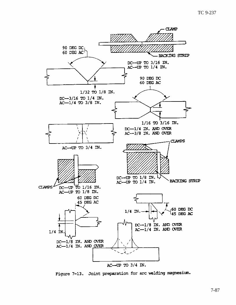
TC 9-237
7-87

TC 9-237
7-20. MAGNESIUM WELDING (cont)
(2) Direct current machines of the constant current type operating onstraight polarity (electrode positive) and alternating current machines are usedwith a high frequency current superimposed on the welding current. Both alternat-ing and direct current machines are used for thin gauge material. However, becauseof better penetrating power, alternating current machines are used on material over3/16 in. (4.8 mm) thick. Helium is considered more practical than argon for usewith direct current reverse polarity. However, three times as much helium by vol-me as argon is required for a given amount of welding. Argon is used with alter-nating current.
(3) The tungsten electrodes are held in a water cooled torch equipped withrequired electrical cables and an inlet and nozzle for the inert gas.
(4) The two magnesium alloys, in the form of sheet, plate, and extrusion,that are most commonly used for applications involving welding are ASTM-1A (FedSpec QQ-M-54), which is alloyed with manganese, and ASTM-AZ31A (Fed SPec QQ-44),which is alloyed with aluminum, manganese, and zinc.
(5) In general, less preparation is required for welding with alternatingcurrent than welding with direct current because of the greater penetration ob-tained. Sheets up to 1/4 in. (6. 4 mm) thickness may be welded from one side with asquare butt joint. Sheets over 1/4 in. (6. 4 mm) thickness should be welded fromboth sides whenever the nature of the structure permits, as sounder welds may beobtained with less warpages. For a double V joint, the included angle should ex-tend from both sides to leave a minimum 1/16 in. (1.6 mm) root face in the centerof the sheets. When welding a double V joint, the back of the first bead should bechipped out using a chipping hammer fitted with a cape chisel. Remove oxide film,dirt, and incompletely fused areas before the second bead is added. In this man-ner, maximum soundness is obtained.
(6) The gas should start flowing a fraction of a second before the arc isstruck. The arc is struck by brushing the electrode over the surface. With alter-nating current, the arc should be started and stopped by means of a remote controlswitch. The average arc length should be about 1/8 in. (3.2 mm) when using heliumand 1/16 in. (1.6 mm) when using argon. Current data and rod diameter are shown intable 7-24.
(7) When welding with alternating current, maximum penetration is obtainedwhen the end of the electrode is held flush with or slightly below the surface ofthe work. The torch should be held nearly perpendicular to the surface of thework, and the welding rod added from a position as neatly parallel with the work aspossible (fig. 7-14). The torch should have a slightly leading travel angle.
7-88

TC 9-237
1Dimensions are given in inches.2Currents shown are for all alloys except alloy Ml, which requires 5 to 10
amperes more current for materials up to 0.05 in. (1.27 mm) thick and 15 to 30amperes more current for thicker materials. Currents given are for welding speeds
3of 12 in. (304.8 mm) per minute.
Sheets thicker than 0.15 in. (3.81 mm) should be welded in more than one pass.A current of about 60 amperes is used on the first pass and the currents given inthe table are used for subsequent passes.
7-89

TC 9-237
7-20. MAGNESIUM WELDING (cont)
(8) Welding should progress in a straight line at a uniform speed. Thereshould be no rotary or weaving motion of the rod or torch, except for larger cornerjoints or fillet welds. The welding rod can be fed either continuously or intermit-tently. Care should be taken to avoid withdrawing the heated end from the protec-tive gaseous atmosphere during the welding operation. The cold wire filler metalshould be brought in as near to horizontal as possible (on flat work). The fillerwire is added to the leading edge of the weld puddle. Runoff tabs are recommendedfor welding any except the thinner metals. Forehand welding, in which the weldingrod precedes the torch in the direction of welding, is preferred. If stops arenecessary, the weld should be started about 1/2 in. (12.7 mm) back from the end ofthe weld when welding is resumed.
(9) Because of the high coefficient of thermal expansion and conductivity,control of distortion in the welding of magnesium requires jigging, small beads,and a properly selected welding sequence to help minimize distortion. Magnesiumparts can be straightened by holding them in position with clamps and heating to300 to 400 OF (149 to 204 0C). If this heating is done by local torch application,care must be taken not to overheat the metal and destroy its properties.
(10) If cracking is encountered during the welding of certain magnesiumalloys, starting and stopping plates may be used to overcome this difficult.These plates consist of scrap pieces of magnesium stock butted against oppositeends of the joint to be welded as shown in A, figure 7-15. The weld is started onone of the abutting plates, continued across the junction along the joint to bewelded, and stopped on the opposite abutting plate. If a V groove is used, theabutting plates should also be grooved. An alternate method is to start the weldin the middle of the joint and weld to each edge (B, fig. 7-15). Cracking may alsobe miniimized by preheating the plate and holding the jig to 200 to 400 0F (93 to204 0C) by increasing the speed of the weld.
7-90

TC 9-237
(11) Filler reds must be of the same composition as the alloy being joinedwhen arc welding. One exception is when welding AZ31B. In this case, grade C rod(MIL-R-6944), which produces a stronger weld metal, is used to reduce cracking.
(12) Residual stress should be relieved through heat treatment. Stressrelief is essential so that lockup stresses will not cause stress corrosion crack-ing . ded stress relieving treatment for arc welding magnesium sheet isThe recommenshown in table 7-25.
(13) The only cleaning required after arc welding of magnesium alloys iswire brushing to remove the slight oxide deposit on the surface. Brushing mayleave traces of iron, which may cause galvanic corrosion. If necessary, clean asin b above. Arc welding smoke can be removed by immersing the parts for 1/2 to 2minutes at 180 to 212 0F (82 to 100 0C), in a solution composed of 16 oz (453 g)tetrasodium pyrophosphate (Na4P2O2), 16 oz (453 g) sodium metaborate (NaB02), andenough water to make 1 gallon (3.8 1).
(14) Welding procedure schedules for GTAW of magnesium (TIG welding) areshown in table 7-26, p 7-92.
h. Gas Metal-Arc (MIG) Welding of Magnesium (GMAW). The gas metal arc weldingprocess is used for the medium to thicker sections. It is considerably faster thangas tungsten arc welding. Special high-speed gear ratios are usually required inthe wire feeders since the magnesium electrode wire has an extremely high meltoffra te . The normal wire feeder and power supply used for aluminum welding is suit-able for welding magnesium. Different types of arc transfer can be obtained whenwelding magnesium. This is primarily a matter of current level or current densityand voltage setting. The short-circuiting transfer and the spray transfer arerecommended. Argon is usually used for gas metal arc welding of magnesium; howev-er, argon-helium mixtures can be used. In general, the spray transfer should beused on material 3/16 in. (4.8 mm) and thicker and the short-circuiting arc usedfor thinner metals. Welding procedure schedules for GMAW of magnesium (MIG weld-ing) are shown in table 7-27, p 7-93.
i . Other Welding Processes. Magnesium can be welded using the resistance weld-ing processes, including spot welding, seam welding, and flash welding. Magnesiumcan also be joined by brazing. Most of the different brazing techniques can beused. In all cases, brazing flux is required and the flux residue must be complete-ly removed from the finish part. Soldering is not as effective, since the strengthof the joint is relatively low. Magnesium can also be stud welded, gas welded, andplasma-arc welded.
7-91


TC 9-237
7-21. TITANIUM
a. General.
WELDING
(1) Titanium is acorrosion resistance. Itstrength increases as the
metal with very goodand its tensilelow impact and creep
strengths. It has seizing tendencies at temperatures above 800 0F (427 0C).
soft, silvery white, medium strengthhas a high strength to weight ratio,temperature decreases. Titanium has
(2) Titanium has a high affinity for oxygen and other gases at elevatedtemperatures, and for this reason, cannot be welded with any process that utilizesfluxes, or where heated metal is exposed to the atmosphere. Minor amounts of impu-rities cause titanium to become brittle.
(3) Titanium has the characteristic known as the ductile-brittle transi-t ion. This refers to a temperature at which the metal breaks in a brittle manner,rather than in a ductile fashion. The recrystallization of the metal during weldingcan raise the transition temperature. Contamination during the high temperateperiod and impurities can raise the transition temperature period and impuritiescan raise the transition temperature so that the material is brittle at room temper-atures. If contamination occurs so that transition temperature is raised suffi-ciently, it will make the welding worthless. Gas contamination can occur at temper-atures below the melting point of the metal. These temperatures range from 700 0F(371 0C) up to 1000 0F (538 0C).
(4) At room temperature, titanium has an impervious oxide coating that re-sists further reaction with air. The oxide coating melts at temperatures consider-ably higher than the melting point of the base metal and creates problems. Theoxidized coating may enter molten weld metal and create discontinuities which great-ly reduce the strength and ductility of the weld.
(5) The procedures for welding titanium and titanium alloys are similar toother metals. Some processes, such as oxyacetylene or arc welding processes usingactive gases, cannot be used due to the high chemical activity of titanium and itssensitivity to embrittlement by contamination. Processes that are satisfactory forwelding titanium and titanium alloys include gas shielded metal-arc welding, gastungsten arc welding, and spot, seam, flash, and pressure welding. Special proce-dures must be employed when using the gas shielded welding processes. These spe-cial procedures include the use of large gas nozzles and trailing shields to shieldthe face of the weld from air. Backing bars that provide inert gas to shield theback of the welds from air are also used. Not only the molten weld metal, but thematerial heated above 1000 0F (538 0C) by the weld must be adequately shielded inorder to prevent embrittlement. All of these processes provide for shielding ofthe molten weld metal and heat affected zones. Prior to welding, titanium and itsalloys must be free of all scale and other material that might cause weld contamina-t ion.
7-94

TC 9-237
b. Surface Preparation.WARNING
The nitric acid used to preclean titanium for inert gas shield arcwelding is highly toxic and corrosive. Goggles, rubber gloves, andrubber aprons must be worn when handling acid solutions. Donot inhale gases and mists. When spilled on the body or clothing, washimmediately with large quantities of cold water, and seek medicalhelp. Never pour water into acid when preparing the solution; instead,pour acid into water. Always mix acid and water slowly. Perform clean-ing operations only in well ventilated places.
The caustic chemicals (including hydrode) used to preclean tita-nium for inert gas shielded arc welding are highly toxic and corro— sive. Goggles, rubber gloves, and rubber aprons must be worn whenhandling these chemicals. Do not inhale gases or mists. When spilledon the body or clothing, wash immediately with large quantities of coldwater and seek medical help. Special care should be taken at all timesto prevent any water from coming in contact with the molten bath or anyother large amount of sodium hydride, as this will cause the fomationof highly explosive hydrogen gas.
(1) Surface cleaning is important in preparing titanium and its alloys forwelding. Proper surface cleaning prior to welding reduces contamination of theweld due to surface scale or other foreign materials. Small amounts of contamina-tion can render titanium completely brittle.
(2)tion of theas follows:
ature; ie . ,
Several cleaning procedures are used, depending on thebase and filler metals. Surface conditions most often
(a) Scale free (as received from the mill).
surface condi-encountered are
(b) Light scale (after hot forming or annealing at intermediate temper-less than 1300 0F (704 0C).
(c) Heavy scale (after hot forming, annealing, or forging at hightemperature).
(3) Metals that are scale free can be cleaned by simple decreasing.
(4) Metals with light oxide scale should be cleaned by acid pickling. Inorder to minimize hydrogen pickup, pickling solutions for this operation shouldhave a nitric acid concentration greater than 20 percent. Metals to be weldedshould be pickled for 1 to 20 minutes at a bath temperature from 80 to 160 OF (27to 71 0C). After pickling, the parts are rinsed in hot water.
(5) Metals with a heavy scale should be cleaned with sand, grit, orvaporblasting, molten sodium hydride salt baths, or molten caustic baths. Sand,grit, or vaporblasting is preferred where applicable. Hydrogen pickup may occurwith molten bath treatments, but it can be minimized by controlling the bath temper-ature and pickling time. Bath temperature should be held at about 750 to 850 0F(399 to 454 0C). Parts should not be pickled any longer than necessary to removescale. After heavy scale is removed, the metal should be pickled as described in(4) above.
7-95

TC 9-237
7-21. TITANIUM WELDING (cont)
(6) Surfaces of metals that have undergone oxyacetylene flame cutting opera-tions have a very heavy scale, and may contain microscopic cracks due to excessivecontamination of the metallurgical characteristics of the alloys. The best clean-ing method for flame cut surfaces is to remove the contaminated layer and anycracks by machining operations. Certain alloys can be stress relieved immediatelyafter cutting to prevent the propagation of these cracks. This stress relief isusually made in conjunction with the cutting operation.
c. MIG or TIG Welding of titanium.
(1) General. Both the MIG and TIG welding processes are used to weld tita-nium and titanium alloys. They are satisfactory for manual and automatic installa-tions. With these processes, contamination of the molten weld metals and adjacentheated zones is minimized by shielding the arc and the root of the weld with inertgases (see (2)(b)) or special backing bars (see (2)(c)). In some cases, inert gasfiller welding chambers (see (3)) are used to provide the required shielding. Whenusing the TIG welding process, a thoriated tungsten electrode should be used. Theelectrode size should be the smallest diameter that will carry the welding cur-rent. The electrode should be ground to a point. The electrode may extend 1-1/2times its diameter beyond the end of the nozzle. Welding is done with direct cur-rent, electrode negative (straight polarity). Welding procedure for TIG weldingtitanium are shown in table 7-28. Selection of the filler metal will depend uponthe titanium alloys being joined. When welding pure titanium, a pure titanium wireshould be used. When welding a titanium alloy, the next lowest strength alloyshould be used as a filler wire. Due to the dilution which will take place diningwelding, the weld deposit will pick up the required strength. The same considera-tions are true when MIG welding titaniun.
(2) Shielding.
(a) General . Very good shielding conditions ue necessary to producearc welded joints with maximum ductility and toughness. To obtain these condi-tions, the amount of air or other active gases which contact the molten weld metalsand. adjacent heated zones must be very low. Argon is normally used with the gas-shielded process. For thicker metal, use helium or a mixture of argon and helium.Welding grade shielding gases are generally free from contamination; however, testscan be made before welding. A simple test is to make a bead on a piece of cleanscrap titanium, and notice its color. The bead should be shiny. Any discolorationof the surface indicates a contamination. Extra gas shielding provides protectionfor the heated solid metal next to the weld metal. This shielding is provided byspecial trailing gas nozzles, or by chill bars laid immediately next to the weld.Backup gas shielding should be provided to protect the underside of the weldjoint . Protection of the back side of the joint can also be provided by placingchill bars in intimate contact with the backing strips. If the contact is closeenough, backup shielding gas is not required. For critical applications, use aninert gas welding chamber. These can be flexible, rigid, or vacuum-purge chambers.
7-96


TC 9-237
7-21. TITANIUM WELDING (cont)
(b) Inert gases. Both helium and argon are used as the shieldinggases. With helium as the shielding gas high welding speeds and better penetrationare obtained than with argon, but the arc is more stable in argon. For open airwelding operations, most welders prefer argon as the shielding gas because itsdensity is greater than that of air. Mixtures of argon and helium are also used.With ‘mixtures, the arc characteristics of both helium and argon are obtained. Themixtures usually vary in composition from about 20 to 80 percent argon. They areoften used with the consumable electrode process. To provide adequate shieldingfor the face and root sides of welds, special precautions often are taken. Theprecautions include the use of screens and baffles (see (c) 3), trailing shields(see (c) 7), and special backing fixtures (see (c) 10) in open air welding, and theuse of inert gas filler welding chambers.
(c) Open air welding.
1. In open air welding operations, the methods used to shield theface of the weld vary with joint design, welding conditions, and the thickness ofthe materials being joined. The most critical area in regard to the shielding isthe molten weld puddle. Impurities diffuse into the molten metal very rapidly andremain in solution. The gas flowing through a standard welding torch is sufficientto shield the molten zone. Because of the loW thermal conductivity of titanium,however, the molten puddle tends to be larger than most metals. For this reasonand because of shielding conditions required in welding titanium, larger nozzlesare used on the welding torch, with proportionally higher gas flows that are re-quired for other metals. Chill bars often are used to limit the size of the puddle.
2. The primary sources of contamination in the molten weld puddleare turbulence in-the gas flow, oxidation of hot filler reds, insufficient gasflow, small nozzles on the welding torch, and impure shielding gases. The latterthree sources are easily controlled.
3. If turbulence occurs in the gas flowing from the torch, airwill be inspired and contamination will result. Turbulence is generally caused byexcessive amounts of gas flowing through the torch, long arc lengths, air currentsblowing across the weld, and joint design. Contamination from this source can beminimized by adjusting gas flows and arc lengths, and by placing baffles alongsidethe welds. Baffles protect the weld from drafts and tend to retard the flow ofshielding gas from the joint area. Chill bars or the clamping toes of the weldingjig can serve as baffles (fig. 7-16). Baffles are especially important for makingcorner type welds. Additional precautions can be taken to protect the operationfrom drafts and turbulence. This can be achieved by erecting a canvas (or othersuitable material) screen around the work area.
4. In manual welding operations with the tungsten-arc process,oxidation of the hot filler metal is a very important source of contamination. Tocontrol it, the hot end of the filler wire must be kept within the gas shield ofthe welding torch. Welding operators must be trained to keep the filler wireshielded when welding titanium and its alloys. Even with proper manipulation,however, contamination from this source probably cannot be eliminated completely.
7-98

TC 9-237
5 . Weld contamination which occurs in the molten weld puddle isespecially hazardous. The impurities go into solution, and do not cause discolora-tion. Although discolored welds may have been improperly shielded while molten,weld discoloration is usually caused by contamination which occurs after the weldhas solidified.
6. Most of the auxiliary equipment used on torches to weld titani-um is designed to improve shielding conditions for the welds as they solidify andcool. However, if the welding heat input is low and the weld cools to temperaturesbelow about 1200 to 1300 OF (649 to 704 0C) while shielded, auxiliary shieldingequipment is not required. If the weld is at an excessively high temperature afterit is no longer shielded by the welding torch, auxiliary shielding must be supplied.
7. Trailing shields often are used to supply auxiliary shield-ing . These shields extend behind the welding torch and vary considerably in size,shaper and design. They are incorporated into special cups which are used on thewelding torch, or may consist only of tubes or hoses attached to the torch or manip-ulated by hand to direct a stream of inert gas on the welds. Figure 7-17 shows adrawing of one type of trailing shield currently in use. Important features ofthis shield are that the porous diffusion plate allows an even flow of gas over theshielded area. This will prevent turbulence in the gas stream The shield fits onthe torch so that a continuous gas stream between the torch and shield is obtained.
7-99

TC 9-237
7-21. TITANIUM WELDING (cont)
8. Baffles are also beneficial in improving shielding conditionsfor welds by retarding the flow of shielding gas from the joint area. Baffles maybe placed alongside the weld, over the top, or at the ends of the weld. In someinstances, they may actually form a chamber around the arc and molten weld puddle.Also, chill bars may be used to increase weld cooling rates and may make auxiliary
9 . Very little difficulty has been encountered in shielding theface of welds in automatic welding operations. However, considerable difficulty has been encountered in manual operations.
1 0 . In open air welding operations, means must be provided forshielding the root or back of the welds. Backing fixtures are often used for thispurpose. In one type, an auxiliary supply of inert gas is provided to shield the back of the weld. In the other, a solid or grooved backing bar fits tightlyagainst the back of the weld and provides the required shilding. Fixtures whichprovide an inert gas shield are preferred, especiallly in manual welding operationswith low welding speeds. Figure 7-18 shows backing fixtures used in butt weldingheavy plate and thin sheet, respectively. Similar types of fixtures are used forother joint designs. However, the design of the fixtures varies with the design of the joints. For fillet welds on tee joints, shielding should be supplied for twos i d e s o f t h e w e l d i n a d d i t i o n t o s h i e l d i n g t h e f a c e o f t h e w e l d .
7-100

TC 9-237
11 . For some applications, it may be easier to enclose the back ofthe weld, as in a tank, and supply inert gas for shielding purposes. This methodis necessary in welding tanks, tubes, or other enclosed structures where access tothe back of the weld is not possible. In some weldments, it may be necessary tomachine holes or grooves in the structures in order to provide shielding gas forthe back or root of the welds.
WARNINGWhen using weld backup tape, the weld must be allowed to cool for sever-al minutes before attempting to remove the tape from the workpiece.
12. Use of backing fixtures such as shown in figure 7-18 can beeliminated in many cases by the use of weld backup tape. This tape consists of acenter strip of heat resistant fiberglass adhered to a wider strip of aluminumfoil, along with a strip of adhesive on each side of the center strip that is usedto hold tape to the underside of the tack welded joint. During the welding, thefiberglass portion of the tape is in direct contact with the molten metal, prevent-ing excessive penetration. Contamination or oxidation of the underside of the weldis prevented by the airtight seal created by the aluminum foil strip. The tape canbe used on butt or corner joints (fig. 7-19) or, because of its flexibility, oncurved or irregularly shapedmust be cleanto allow full
and dry. Bestpenetration.
surfaces. The surf ace to which the tape is appliedresults are obtained by using a root gap wide enough
7-101

TC 9-237
7-21. TITANIUM WELDING (cont)
13. Bend or notch toughness tests are the best methods for evaluat-ing shielding conditions, but visual inspection of the weld surface, which is notan infallible method, is the only nondestructive means for evaluating weld qualityat the present time. With this method, the presence of a heavy gray scale with anonmetallic luster on the weld bead indicates that the weld has been contaminatebadly and has low ductility. Also, the weld surface may be shiny but have differ-ent colors, ranging from grayish blue to violet to brown. This type of discolora-tion may be found on severely contaminated welds or may be due only to surfacecontamination, while the weld itself may be satisfactory. However, the quality ofthe weld cannot be determined without a destructive test. With good shieldingprocedures, weld surfaces are shiny and show no discoloration.
(3) Welding chambers.
(a) For some applications, inert gas filled welding chambers areused. The advantage of using such chambers is that good shielding may be obtainedfor the root and face of the weld without the use of special fixtures. Also, thesurface appearance of such welds is a fairly reliable measure of shielding condi-tions. The use of chambers is especially advantageous when complex joints arebeing welded. However, chambers are not required for many applications, and theiruse may be limited.
(b) Welding chambers vary in size and shape, depending on their useand the size of assemblies to be welded. The inert atmospheres maybe obtained byevacuating the chamber and filling it with helium or argon, purging the chamberwith inert gas, or collapsing the chamber to expel air and refilling it with aninert gas. Plastic bags have been used in this latter manner. when the atmo-spheres are obtained by purging or collapsing the chambers, inert gas usually issupplied through the welding torch to insure complete protection of the welds.
(4) Joint designs. Joint designs for titanium are similar to those usedfor other metals. For welding a thin sheet, the tungsten-arc process generally isused. With this process, butt welds may be made with or without filler rod, depend-ing on the thickness of the joint and fitup. Special shearing procedures somtimesare used so that the root opening does not exceed 8 percent of the sheet thick-ness. If fitup is this good, filler rod is not required. If fitup is not thisgood, filler metal is added to obtain full thickness joints. In welding thickersheets (greater than 0.09 in. (2.3 mm) ), both the tungsten-arc and consumable elec-trode processes are used with a root opening. For welding titanium plates, bars,or forgings, both the tungsten-arc and consumable electrode processes also are usedwith single and double V joints. In all cases, good weld penetration may be ob-tained with excessive drop through. However, penetration and dropthrough are con-trolled more easily by the use of proper backing fixtures.
N O T EBecause of the low thermal conductivity of titanium, weld beads tend tobe wider than normal. However, the width of the beads is generally con-trolled by using short arc lengths, or by placing chill bars or theclamping toes of the jig close to the sides of the joints.
7-102

TC 9-237
(5) Welding variables.
(a) Welding speed and current for titanium alloys depend on the pro-cess used, shielding gas, thickness of the material being welded, design of thebacking fixtures, along with the spacing of chill bars or clamping bars in thewelding jig.per minute.process. Intungsten-arccess.
Welding speeds vary from about 3.0 to 40.0 in. (76.2 to 1016.0 mm)The highest welding speeds are obtained with the consumable electrodemost cases, direct current is used with straight polarity for theprocess. Reverse polarity is used for the consumable electrode pro-
(b) Arc wander has proven troublesome in some automatic welding opera-tions. With arc wander, the arc from the tungsten or consumable electrode movesfrom one side of the weld joint to the other side. A straight, uniform weld beadwill not be produced. Arc wander is believed to be caused by magnetic disturbanc-es, bends in the filler wire, coatings on the filler wire, or a combination ofthese. Special metal shields and wire straighteners have been used to overcome arcwander, but have not been completely satisfactory. Also, constant voltage weldingmachines have been used in an attempt to overcome this problem. These machinesalso have not been completely satisfactory.
(c) In setting up arc welding operations for titanium, the weldingconditions should be evaluated on the basis of weld joint properties and appear-ance. Radiographs will show if porosity or cracking is present in the weld joint.A simple bend test or notch toughness test will show whether or not the shieldingconditions are adequate. A visual examination of the weld will show if the weldpenetration and contour are satisfactory. After adequatelished, careful controls are desirable to ensure that thenot changed.
(6) Weld defects.
(a) General . Defects in arc welded joints in
procedures are estab-shielding conditions are
titanium alloys consistmainly of porosity (see (b)) and cold cracks (see (c)). Weld penetration can becontrolled by adjusting welding conditions.
(b) Poros i ty . Weld porosity is a major problem in arc welding titani-um alloys. Although acceptable limits for porosity in arc welded joints have notbeen establish, porosity has been observed in tungsten-arc welds in practicallyall of the alloys which appear suitable for welding operations. It does not extendto the surface of the weld, but has been detected in radiographs. It usually oc-curs close to the fusion line of the welds. Weld porosity may be reduced by agitat-ing the molten weld puddle and adjusting welding speeds. Also, remelting the weldwill eliminate some of the porosity present after the first pass. However, thelatter method of reducing weld porosity tends to increase weld contamination.
7-103

TC 9-237
7-21. TITANIUM
(c)
should not be a
WELDING (cont)
Cracks.
1. With adequate shielding procedures and suitable alloys, cracksproblem. However, cracks have been troublesome in welding some
alloys. Weld cracks are attributed to a number of causes. In commercially puretitanium, weld metal cracks are believed to be caused by excessive oxygen or nitro-gen contamination. These cracks are usually observed in weld craters. In some ofthe alpha-beta alloys, transverse cracks in the weld metal and heat affected zonesare believed to be due to the low ductility of the weld zones. However, cracks inthese alloys also may be due to contamination. Cracks also have been observed inalpha-beta welds made under restraint and with high external stresses. Thesecracks are sometimes attributed to the hydrogen content of the alloys.
NOTEIf weld cracking is due to contamination, it may be controlled by im-proving shielding conditions. However, repair welding on excessivelycontaminated welds is not practical in many cases.
2. Cracks which are caused by the loW ductility of welds inalpha-beta alloys–can be prevented by heat treating or stress relieving the weld-ment in a furnance immediately after welding. Oxyacetylene torches also have beenused for this purpose. However, care must be taken so that the weldment is notoverheated or excessively contaminated by the torch heating operation.
3. Cracks due to hydrogen may be prevented by vacuum annealingtreatments prior to welding.
(7) Availability of welding filler wire. Most of the titanium alloys whichare being used in arc welding applications are available as wire for use as weldingfiller metal. These alloys are listed below:
(a) Commercially pure titanium — commercially available as wire.
t i e s .(b) Ti-5Al-2-l/2Sn alloy
(c) Ti-1-l/2Al-3Mn alloyt i e s .
-- available as wire in experimental quanti-
-- available as wire in experimental quanti
(d) Ti-6Al-4V alloy -- available as wire in experimental quantities.
(e) There has not been a great deal of need for the other alloys aswelding filler wires. However, if such a need occurs, most of these alloys alsocould be reduced to wire. In fact, the Ti-8Mn alloy has been furnished as weldingwire to met some requests.
d. Pressure Welding. Solid phase or pressure welding has been used to jointitanium and titanium alloys. In these Processes, the surfaces to be jointed arenot melted. They are held-together under pressure and heated to elevated temperatures (900 to 2000 0F (482 to 1093 0C)).welding is the oxyacetylene flame. With
One methd of heating used in pressuresuitable pressure and upset, good welds
7-104

TC 9-237
are obtainable in the high strength alpha-beta titanium alloys. The contaminatedarea on the surface of the weld is displaced from the joint area by the upset,which occurs during welding. This contaminated surface is machined off after weld-ing. Another method of heating is by heated dies. Strong lap joints are obtainedwith this method in commercially pure titanium and a high strength alpha-beta al-loy. By heating in this manner, welds may be made in very short periods of time,and inert gas shielding may be supplied to the joint. With all of the heatingmethods, less than 2 minutes is required to complete the welding operation. Withsolid phase or pressure welding processes, it is possible to produce ductile weldsin the high strength alpha-beta alloys by using temperatures which do not causeembrittlement in these alloys.
7-22. NICKEL AND MONTEL WELDING
a. General. Nickel is a hard, malleable, ductile metal. Nickelare commonly used when corrosion resistance is required. Nickel and
and its alloysnickel alloys
such as Monel can, in general, be welded by metal-arc and gas welding methods. Some nickel alloys are more difficult to weld due to different compositions. Theoperator should make trial welds with reverse polarity at several current valuesand select the one best suited for the work. Generally, the oxyacetylene weldingmethods are preferred for smiler plates. However, small plates can be welded bythe metal-arc and carbon-arc processes, and large plates are most satisfactorilyjoined, especially if the plate is nickel clad steel.
When welding, the nickel alloys can be treated much in the same manner asaustenitic stainless steels with a few exceptions. These exceptions are:
(1)temperaturemetal.
(2)
The nickel alloys will acquire a surface or coating which melts at aapproximately 1000 0F (538 0C) above the melting point of the base
The nickel alloys are susceptible to embrittlement at welding tempera-tures by lead, sulfur, phosphorus, and some low-temperature metals and alloys.
(3) Weld penetration is less than expected with other metals.
When compensation is made for these three factors, the welding procedures used forthe nickel alloys can he the same as those used for stainless steel. This is be-cause the melting point, the coefficient of thermal expansion, and the thermalconductivity are similar to austenitic stainless steel.
It is necessary that each of these precautions be considered. The surface oxideshould be completely removed from the joint area by grinding, abrasive blasting,machining, or by chemical means. When chemical etches are used, they must be com-pletely removed by rinsing prior to welding. The oxide which melts at temperaturesabove the melting point of the base metal may enter the weld as a foreign material,or impurity, and will greatly reduce the strength and ductility of the weld. Theproblem of embrittlement at welding temperatures also means that the weld surfacemust be absolutely clean. paints, crayon markings, grease, oil, machining lubri-cants, and cutting oils may all contain the ingredients which will causeembrittlement. They must be completely removed for the weld area to avoidembrittlement. It is necessary to increase the opening of groove angles and toprovide adequate root openings when full-penetration welds are used. The bevel orgroove angles should be increased to approximately 40 percent over those used forcarbon steel.
7-105

TC 9-237
7-22. NICKEL AND MONEL WELDING (cont)
b. Joint Design. Butt joints are preferred but corner and lap joints can beeffectively welded. Beveling is not required on plates 1/16 to 1/8 in. (1.6 to 3.2mm) thick. With thicker materials, a bevel angle of 35 to 37-1/2 degrees should bemade. When welding lap joints, the weld should be made entirely with nickel elec-trodes if water or air tightness is required.
c. Welding Techniques.
(1) Clean all surfaces to be welded either mechanically by machine, sand-blasting, grinding, or with abrasive cloth; or chemically by pickling.
(2) Plates having U or V joints should be assembled, and if nickel cladsteel, should be tacked on the steel side to prevent warping and distortion. Afterit is determined that the joint is even and flat, complete the weld on the steelside. Chip out and clean the nickel side and weld. If the base metal on bothsides is nickel, clean out the groove on the unwelded side prior to beginning theweld on that side.
(3) If desired, the nickel side maybe completed first. However, the steelside must be tacked and thoroughly cleaned and beveled (or gouged) down to the rootof the nickel weld prior to welding.
(4) Lap and corner joints are successfully welded by depositing a bead ofnickel metal into the root and then weaving successive beads over the root weld.
(5) The arc drawn for nickel or nickel alloy welding should be slightlyshorter than that used in normal metal-arc welding. A 1/16 to 1/8 in. (1.6 to 3.2mm) arc is a necessity.
(6) Any position weld can be accomplished that can be satisfactorily weldedby normal metal-arc welding of steel.
d. Welding Methods.
(1) Almost all the welding processes can be used for welding the nickelalloys. In addition, they can be joined by brazing and soldering.
(2) Welding nickel alloys. The most popular processes for welding nickelalloys are the shielded metal arc welding process,the gas tungsten arc weldingprocess, and the gas metal arc welding process. Process selection depends on thenormal factors. When shielded metal arc welding is used the procedures are essen-tially the same as those used for stainless steel welding.
The welding procedure schedule for using gas tungsten arc welding (TIG) is shown bytable 7-29. The Welding procedure schedule for gas metal arc welding (MIG) isshown by table 7-30, p 7-108. The procedure information set forth on these tableswill provide starting points for developing the welding procedures.
(3) NO postweld heat treatment is required to maintain or restore corrosionresistance of the nickel alloys. Heat treatment is required for precipitatinghardening alloys. Stress relief may be required to meet certain specifications toavoid stress corrosion cracking in applications involving hydrofluoric acid vaporsor caustic solutions.
7-106

