chapter 7 water supply master plan - jica ...open_jicareport.jica.go.jp/pdf/11888070_06.pdf7 - 1 7.1...
TRANSCRIPT

CHAPTER 7
WATER SUPPLY MASTER PLAN
7 - 1
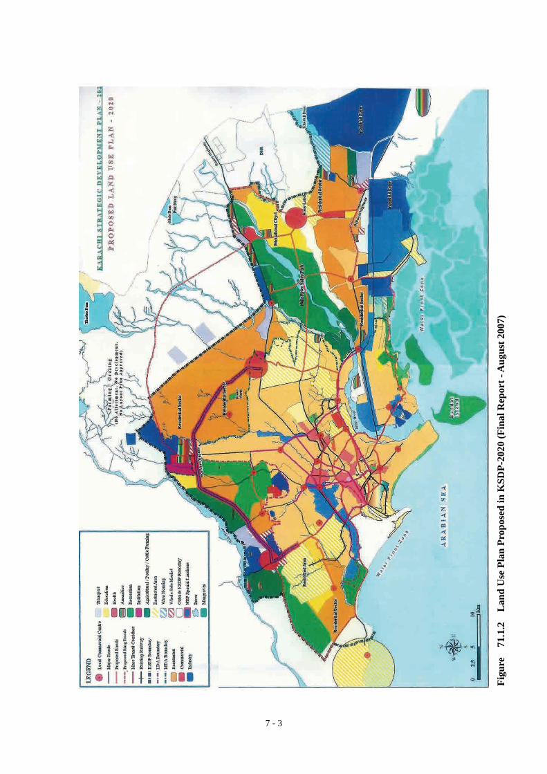
7.1 PLANNING ASSUMPTIONS This section discusses the planning assumptions, based upon which our master plan for the water supply system in Karachi has been formulated. 7.1.1 Population and Development Patterns In August 2007, CDGK issued the final report on Karachi Strategic Development Plan 2020 (Final Report, August 2007). This report indicated that the total population of Karachi was 15.2 million in 2005 and it would increase to 27.5 million in 2020. The report also predicted that more than 45% of the projected population increase during the 15 years from 2005 to 2020 would occur in the three towns located on the outskirts of the Karachi City, namely Keamari, Gadap and Bin Qasim whereas the other 55% would occur in the remaining 15 towns. This was based on the perception that during the next 15 years significant developments would take place on the outskirts of the city in particular in the southern part of Gadap Town. Figure 71.1.1 shows the population projections made in the Karachi Strategic Development Plan 2020 (Final Report, August 2007). Figure 71.1.2 illustrates the future land use envisaged by the same plan. We believe that the Karachi Strategic Development Plan 2020 (KSDP-2020), once it is approved and authenticated by higher authorities, will serve as a guiding principle, based on which all infrastructure development schemes for all public service sectors, such as water supply, sewerage, solid waste disposal, electricity, gas, telecommunication and roads will be developed. For this reason, we decided to develop a water supply and sewerage master plan for Karachi based on the population projection, future land use patterns and other basic data provided in the KSDP-2020 (Final Report, August 2007).
7 WATER SUPPLY MASTER PLAN
Karachi’s total population was 15.2 million in 2005 and it would increase to 27.5 million in 2020.
It has been predicted that 45% of the population increase during the 15 years from 2005 to 2020 would occur in the three towns located on the outskirts of the Karachi City, namely Keamari, Gadap and Bin Qasim while the other 55% would occur in the remaining 15 towns.

7 - 2
Figure 71.1.1 Population Projection in KSDP-2020 (Final Report - August 2007)
Year 1981 1998 2005 2010 2015 2020Population (1,000) 5,395.4 11,335 15,120 18,529 22,594 27,550Average Annual Growth Rate (%) 4.46% 4.20% 4.15% 4.05% 4.05%
0
5,000
10,000
15,000
20,000
25,000
30,000
1960 1970 1980 1990 2000 2010 2020Year
Popu
latio
n (×
1,0
00)
Census Data (Karachi Development Plan 2000, June 1991)
Population estimated by KSDP-2020
7 - 3
Figu
re
71.1
.2
Lan
d U
se P
lan
Prop
osed
in K
SDP-
2020
(Fin
al R
epor
t - A
ugus
t 200
7)

7 - 4
7.1.2 Water Sources Despite the significant population increase envisaged by the KSDP-2020 (Final Report-August 2007), there has been no definite plan for increasing the capacity of water sources to meet the increasing water demand. In this respect, the KSDP-2020 has proposed the use of several modern technologies to increase the water supply capacity. They include the construction of sea water desalination plants, reuse of effluents from sewage treatment plants for recharging groundwater aquifers, and the development of dual water supply systems and dual sewerage systems. However, most of these technologies are not considered financially viable both at present and in the foreseeable future. Sea water desalination will not provide a viable solution for a mega city like Karachi unless there is a remarkable technical breakthrough that substantially reduce both CAPEX and OPEX of desalination. Our review of existing studies on the development of regional groundwater resources indicated that the exploitability of groundwater in the region is very low. In the light of the immense size of the water demand in the city, there is no doubt that the Indus River will continue to remain as the only viable water source for Karachi in the foreseeable future. This view was first indicated by the 1985 water supply master plan study for Karachi conducted by Sir M. MacDonald and Partners (principal consultant) and Associated Consulting Engineers (local associated consultant). The study made a review of all potential water sources in the Karachi region, which included the Indus River and other surface water and groundwater sources, seawater desalination, and the indirect reuse of treated sewage effluents for the recharge of aquifers and substitution of existing non-potable uses. As a result, the study indicated that the Indus River and desalination are the only two sources that could technically meet a large water demand in Karachi. The study also indicated that the cost of desalination for the foreseeable future was prohibitive and that desalination should therefore be considered as a last resort. The study then concluded that the Indus River was the only viable water source for Karachi. This view was endorsed by a special committee formulated by GOS in 2002. The committee which was comprised of representatives from the Planning and Development Department of GOS, Irrigation and Power Department of GOS, and Karachi Water & Sewerage Board (KW&SB), prepared a report on long term water supply plan for Karachi up to the year 2025. The committee submitted the report to the Central Development Working Party (CDWP) on November 14, 2002, which was evaluating the PC-I of the scheme “Assured Water Supply for Karachi – upgrading Kinjhar Lake System” at that time. In summary, the report provided the following major findings and recommendations.
(Findings) The existing allocation of 1,200 cusecs from the Indus River would be fully utilized in
2005 with completion of the 100 mgd K-III project. The population of Karachi was ever growing and additional requirement up to the year 2025 was estimated to be another 1,200 cusecs thus the total requirement would be 2,400 cusecs.
The present scheme for assuring a water supply for Karachi is considered as Phase-I. This phase is to cater for short-term assured water for Karachi up to the year 2005. Phase-II of this scheme would be required for long-term requirements of water supply in Karachi beyond 2005 and up to 2025.
(Recommendations) To meet the growing water demand of Karachi the water allocation for Karachi up to
Vision 2025 may be increased by another 1,200 cusecs raising the total allocation to 2,400 cusecs by the Government under a national cause without affecting the water supply quota of the Thatta District for agriculture purposes. Once additional allocation was allowed then a 2-stage study programme for system expansion would have to be initiated.

7 - 5
Stage-I: Study by the Irrigation and Power Department of GOS for increasing capacity in the system from the KB Feeder Upper up to the Kinjhar Lake without affecting the stability of the Kotri Barrage.
Stage-II: Feasibility study by KW&SB in consultation with the Irrigation and Power Department for determining the most economically viable, technically feasible and secure route to bring additional 1,200 cusecs of water from the Kinjhar Lake to Karachi.
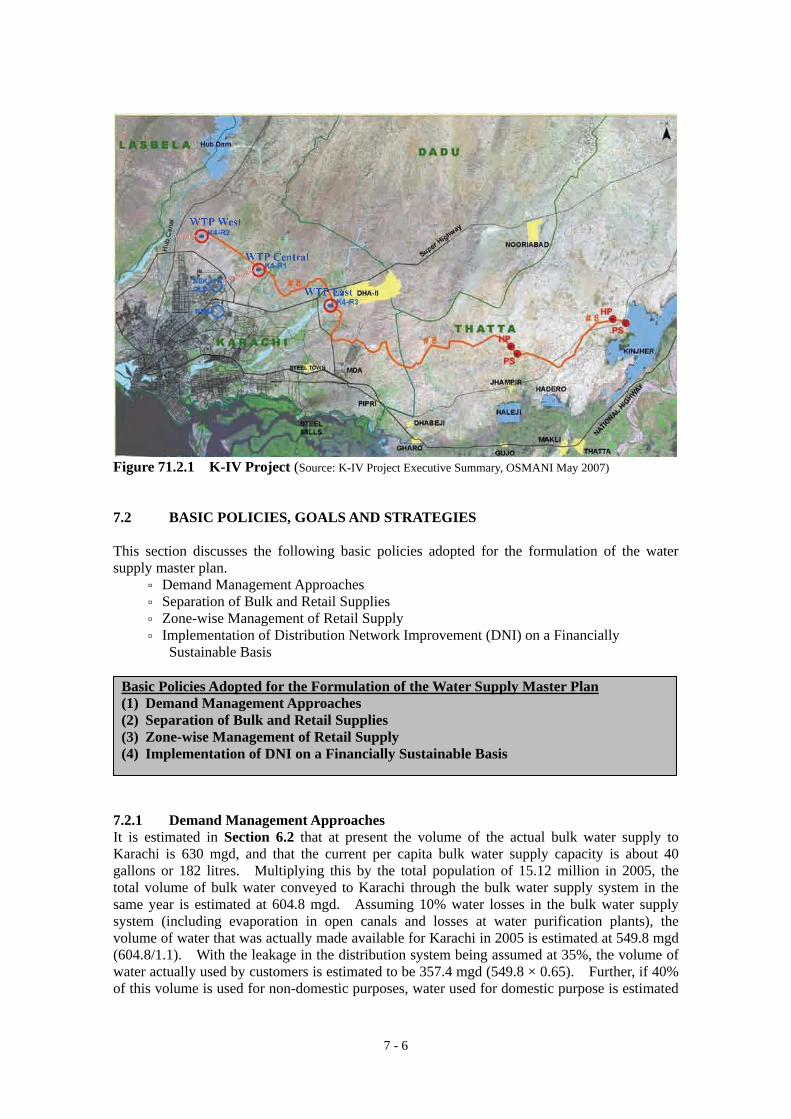
Based on the committee’s recommendations, CDGK requested the GOP to grant an additional quota of 1,200 cusecs (650 mgd) from the Indus River to meet the future water demand of the Karachi City. Furthermore, KW&SB since October 2005 has been conducting the K-IV Study, the main objective of which is to recommend on the most economical and technically viable route for conveying additional 1,200 cusecs of Indus water from the Kinjhar Lake to Karachi. The study examined several alternative routes and recommended the most economical route as a result of the comparison of capital and annual operating costs to be required for each alternative. Further, the study also identified the sites for construction of three water treatment plants each having an ultimate treatment capacity of 260 mgd, 260 mgd and 130 mgd. Figure 71.2.1 shows the locations of the raw water conveyance route and three water treatment plants proposed by the study. In January 2008, President Pervez Musharaff while presiding at the ‘foundation stone unveiling ceremony’ of the ‘Corridor Project’ at Governor’s House assured the Federal Government’s supports towards the implementation of the K-IV Project. A newspaper article describing this event is attached as Appendix A71.1. In developing a water supply master plan for Karachi, the JICA Study assumed that Karachi would be granted an additional quota of 1,200 cusecs from the Indus River and a total of 2,400 cusecs of Indus River water would be made available at the Kinjhar Lake for extraction by KW&SB. This is based on our strong belief that if this additional quota is not granted, then there will be no such a large population increase or significant developments in Karachi as have been envisaged by the KSDP-2020 (Final Report-August 2007). The Department of Irrigation and Power of GOS is currently responsible for the operation and maintenance of the Kotri Barrage, KB Feeder Upper and Kinjhar Lake while KW&SB’s responsibility for the operation and maintenance of the bulk water supply system starts from the KG Canal that withdraws the impounded water of the Kinjhar Lake. It is likely that this demarcation of responsibilities will remain unchanged in the future, and as such, it is assumed that any infrastructure development required for enabling KW&SB to withdraw additional 1,200 cusecs from the Kinjhar Lake would be planned, designed and implemented by GOS and that GOS would also be responsible for the operation and maintenance of such additional infrastructure. Instead, it is assumed that KW&SB would pay GOS a raw water charge at the rate of Rs.0.5 per 1,000 gallons (Rs.0.11 per m3) to compensate GOS for part of the costs incurred with respect to the construction, operation and maintenance of such infrastructure.
Karachi would be granted an additional quota of 1,200 cusecs from the Indus River and a total of 2,400 cusecs of Indus River water would be made available at the Kinjhar Lake for abstraction by KW&SB. If this additional quota is not granted, then there will be no such a large population increase or significant developments in Karachi as have been envisaged by the KSDP-2020 (Final Report - January 2007).
7 - 6
Figure 71.2.1 K-IV Project (Source: K-IV Project Executive Summary, OSMANI May 2007) 7.2 BASIC POLICIES, GOALS AND STRATEGIES This section discusses the following basic policies adopted for the formulation of the water supply master plan.
Demand Management Approaches Separation of Bulk and Retail Supplies Zone-wise Management of Retail Supply Implementation of Distribution Network Improvement (DNI) on a Financially
Sustainable Basis 7.2.1 Demand Management Approaches It is estimated in Section 6.2 that at present the volume of the actual bulk water supply to Karachi is 630 mgd, and that the current per capita bulk water supply capacity is about 40 gallons or 182 litres. Multiplying this by the total population of 15.12 million in 2005, the total volume of bulk water conveyed to Karachi through the bulk water supply system in the same year is estimated at 604.8 mgd. Assuming 10% water losses in the bulk water supply system (including evaporation in open canals and losses at water purification plants), the volume of water that was actually made available for Karachi in 2005 is estimated at 549.8 mgd (604.8/1.1). With the leakage in the distribution system being assumed at 35%, the volume of water actually used by customers is estimated to be 357.4 mgd (549.8 × 0.65). Further, if 40% of this volume is used for non-domestic purposes, water used for domestic purpose is estimated
Basic Policies Adopted for the Formulation of the Water Supply Master Plan (1) Demand Management Approaches (2) Separation of Bulk and Retail Supplies (3) Zone-wise Management of Retail Supply (4) Implementation of DNI on a Financially Sustainable Basis

7 - 7
at 214.4 mgd (357.4 × 0.60). Dividing this by the total served population of 13.608 million, which is 90% of the city’s total population in 2005 (15.12 million) estimated by the KSDP-2020 (Final Report-August 2007), the domestic per capita consumption rate in 2005 is estimated at 15.76 gallons (71.6 litres) per day. No accurate assessment of leakage in the distribution network is possible at present. The per capita consumption rate will further reduce if the actual leakage is greater than 35%. KSDP-2020 estimated that Karachi had a total population of 15.2 million in 2005 and also projected that the total population would increase to 27.5 million by 2020. It is envisaged from this projection that Karachi’s total population could reach 32.0 million in 2025, which is almost double of the present total population. On the other hand, the possible increase in the capacity of water sources over the same period is estimated to be only 1,200 cusecs (650 mgd) as discussed in Section 7.1, which is less than the capacity of existing water sources i.e.720 mgd. These observations suggest that Karachi will continuously be subjected to severe water constraints over the planning horizon of 2025. Karachi is located in the arid region where annual precipitation is as small as 200 mm. There is no prospective surface or underground water source available within or in the vicinity which can be developed in a large scale to cater for the enormous water demand of the mega city. Karachi seems to be one of the few cities in the world, which lies in the arid region, yet accommodates as many as 16 million people. With the exploding population and limited availability of water resources, one must choose whether (a) to provide rather abundant supplies to a limited number of people in the city or (b) to provide essential supplies to as many people in the city as possible. Given the public nature of water supply service, it is obvious that one should choose the latter option. It is therefore extremely important to ensure that this option is successfully implemented through ‘Demand Management Approaches’ which provide both general public and business entities with strong incentives to voluntarily restrict their water consumption for essential purposes only. There should be a consensus reached by all stakeholders that making future water supply development plans based on unconstrained water demands is not a proper approach in the case of Karachi. The central part of the demand management approaches will be the introduction of measured supplies with a volumetric charging system whereby all retail and bulk customers will be charged based on their actual consumption. This will be further reinforced by the introduction of a new water tariff structure which will provide both domestic and non-domestic customers with strong incentives for efficient use of water. Tariffs will be structured to differentiate essential water needs from non-essential water needs. A low tariff would be applied to essential water needs while those who consume beyond essential needs should be severely penalized. Minimizing leakage, wastage and illegal connections will also constitute the core part of the demand management approaches.
Our observations suggest that Karachi will continuously be subjected to severe water constraints over the planning horizon of 2025.
There should be a consensus reached by all stakeholders that making future water supply development plans based on unconstrained water demands is not a proper approach in the case of Karachi.

7 - 8
7.2.2 Separation of Bulk and Retail Supplies KW&SB is currently supplying water to the entire Karachi District and two union councils in the Thatta District of the Sindh Province. In the near future, KW&SB is also expected to supply treated water to the Lasbela District of the Balochistan Province. This demonstrates that KW&SB is playing a role of the regional bulk water supplier. The bulk water supply to two union councils in the Thatta District was initiated based on the notification issued by the GOS on August 23, 2004, which expanded the administrative area of KW&SB to include two union councils in the Thatta District, namely Dhabeji and Gharo. A copy of this notification is attached as Appendix A72.1. The bulk water supply to the Lasbela District of the Balochistan Province was decided by the GOP during the approval process of the K-III project. The PC-1 documents of the project stipulated that out of 100 mgd of Indus water transferred from the Kinjhar Lake to Karachi under the K-III project, 95 mgd would be distributed to Karachi while the remaining 5 mgd to the Lasbela District. In accordance with this PC-1, a 27 km-long, 24-inch diameter water transmission pipeline was constructed from the Hub Filtration Plant to Lasbela as part of the K-III project. GOS and Government of Balochistan (GOB) are currently negotiating over (a) who should be responsible for the operation and maintenance of the transmission pipeline, and (b) the water tariff KW&SB will charge GOB for water it receives from KW&SB. Under the Pakistani constitution, water is a provincial subject. However, GOP also performs a number of functions and responsibilities in the water sector, mostly relating to inter-provincial matters. The water supply to Balochistan under the K-III project is a good example of this. Because of the inclusion of the supply to Balochistan, the K-III project was given a status of an inter-provincial project and the entire project cost was subsidized by GOP. Both GOP and GOS have legitimate roles in shaping of policies and strategies for the water and sanitation
Demand Management Approaches
Goals All consumers in the city including government and business entities are being highly conscious about water conservation and voluntarily restrict their consumption for essential purposes only.
Strategies
Introduction of measured supplies with a volumetric charging system whereby all retail and bulk customers will be charged based on this actual consumption
Introduction of a new water tariff structure which will provide both domestic and non-domestic customers with strong incentives for efficient use of water
Implementation of efficient meter reading, billing and collection Minimizing leakage, wastage and illegal connections Implementation of mass media campaigns for enhancing consumers’ awareness
on water conservation Mandatory use of water-saving equipment and devices in newly constructed
houses and buildings such as low-volume toilets, low-flow showerheads, water faucets with flow restrictors or aerators.
Subsidizing large-scale commercial and industrial users part of their investment costs for water conservation including internal recycling of used water.

7 - 9
sector in the region. It is obvious that the bulk water supplies to the Thatta and Lasbela Districts are the consequence of these policies and strategies. However, it should be noted that these policies and strategies often conflict with sound business and commercial principles. Development of a new bulk water supply scheme to bring water from the Indus River to Karachi requires a large-scale investment which would inevitably exceed the financial capability of the service provider. Thus, part of the investment cost would have to be subsidized either by GOP or GOS. The reality is that in the past the entire capital costs required for the development of the bulk water supply system were subsidized either by GOP or GOS. The cost required for operation and maintenance of the bulk water supply system is also significantly large because of the long distances covered by the system. All these considerations lead to a conclusion that managing the bulk water supply system on a full cost recovery basis would not be feasible - at least within the planning horizon of 2025. On the contrary, retail water supply in Karachi can be managed on a full cost recovery basis with sound business and commercial principles. This is why we recommend the separation of bulk and retail supplies. Figure 72.2.1 demonstrates the basic concept of the proposed separation. Figure 72.2.2 illustrates the relationship between the bulk and retail suppliers after the separation. It is recommended that in the long run bulk and retail supplies should be managed and operated by different organisations.
Figure 72.2.1 Separation of Bulk and Retail Supplies
Retail Supply
Bulk Supply
&
Retail Supply
Bulk Supply Gov’t Subsidy(e.g. 50% of capital costs)
Gov’tSubsidy
EXISTING PROPOSED
Full Cost Recovery(100% of O&M costs,Depreciation and Payment of interests)
Retail Supply
Bulk Supply
&
Retail Supply
Bulk Supply Gov’t Subsidy(e.g. 50% of capital costs)
Gov’tSubsidy
EXISTINGEXISTING PROPOSEDPROPOSED
Full Cost Recovery(100% of O&M costs,Depreciation and Payment of interests)
Managing the bulk water supply system on a full cost recovery basis would not be feasible – at least within the planning horizon of 2025. On the contrary, retail water supply in Karachi can be managed on a full cost recovery basis with sound business and commercial principles. This is why we recommend the separation of bulk and retail supplies.
It is recommended that in the long run bulk and retail supplies be managed and operated by different organizations.

7 - 10
Figure 72.2.2 Bulk and Retail Suppliers after Separation The ultimate objective of the proposed separation is to enable the retail supplier to provide customer-focused, efficient water supply and sewerage services on a financially sustainable basis. This requires the insulation of the retail supplier from external interference in the micromanagement aspects of its operation, including the employment of staff, disciplining workers for poor performance, offering rewards and promotions based on good performance, handling of payment defaulters and illegal/unauthorized connections, recovery of arrears, etc. Experience indicates that as long as retail suppliers are dependent on government subsidies they will remain vulnerable to political interference in the day-to-day management of the services and in the technical execution of projects. It is expected that the proposed separation would enhance the overall efficiency in the operation and maintenance of the water supply system. Since KW&SB in the past has been the only organization responsible for the management and operation of both bulk and retail water supply systems, there has been no absolute necessity for measuring flows at key strategic locations in the system. However, with the separation of the bulk and retail supplies, there will be an absolute necessity for accurately measuring flows at the locations where water is delivered to the retail supplier as shown in Figure 72.2.2.
The ultimate objective of the proposed separation is to enable the retail supplier to provide customer-focused, efficient water supply and sewerage services to its customers. This requires the insulation of the retail supplier from external interference in the micromanagement aspects of its operation.
Experience indicates that as long as retail suppliers are dependent on government subsidies, they will remain vulnerable to political interference in the day-to-day management of services and in the technical execution of projects.

7 - 11
7.2.3 Zone-wise Management of Retail Supply KW&SB has divided the entire Karachi City into five distribution zones, namely Zone I, Zone II-A, Zone II-B, Zone III-A and Zone III-B. This division was made for administrative purposes only, and from the hydraulic point of view each zone is not completely separated from others. Figure 72.3.1 shows the locations of the existing five distribution zones. Zone I straddles the Malir River, and so do Zone II-A and Zone II-B the Lyari River. Zone III-A straddles both rivers. Retail service in each distribution zone is managed by a Zonal Chief Engineer. However, bulk customers in the zone such as cantonments, DHA, PSM, PQA and industries do not fall under his responsibility; they fall under the responsibility of the bulk transmission department. The same department is also responsible for operation and maintenance of water trunk mains that are passing through these distribution zones. Table 72.3.1 presents the towns included in each of these five distribution zone. KSDP-2020 (Final Report-August 2007) discussed in Section 7.1 proposed that the water and wastewater services in Karachi should be managed and operated by each town. This however would not be a feasible option at least in the foreseeable future because of (a) the complexity of the existing water distribution system in which one water trunk main is supplying a number of towns whereas many towns are supplied by more than one water trunk main, and (b) the significant economic disparities between towns, making it difficult for some towns (such as Orangi, Baldia and Lyari) to cross-subsidize tariffs from the rich to the poor because of their weak revenue bases.
Separation of Bulk and Retail Supplies
Goals An institutional framework is in place whereby a competent retail supplier (or suppliers) can provide water supply and sewerage services on a full cost recovery basis with sound business and commercial principles.
Strategies
All stakeholders agree to the separation of the bulk and retail supplies. Conduct a separate study to identify necessary changes to existing laws,
ordinances and regulations and draft detailed legal provisions to put the separation into effect.
Propose such changes for approval of legislators.

7 - 12
Table 72.3.1 Existing Distribution Zones Instead, we propose that Karachi should be divided into three distinct hydraulic zones each separated from the others by two major rivers in Karachi i.e. Malir and Lyari Rivers. The rationale is that there is only a limited number of exiting water mains and sewer pipes that have been laid across these rivers and they can easily be located for installation of isolation valves or bulk flow meters. Further, separation of hydraulic zones by rivers would allow for more prudent approaches for planning of the sewerage system than by the administrative boundaries of the towns. Figure 72.3.2 shows the locations of the proposed three hydraulic zones. Table 72.3.2 presents the towns and cantonments included in each hydraulic zone. Because of its
immense size, Gadap town is separated into the three hydraulic zones with its major part being in the Zone Central. Although the main part of Keamari town is located in the Zone West, a small fraction of the town on the left bank of the Lyari River is included in the Zone Central. The other 16 towns are not divided either by the Malir or Lyari River.
The size of the city is too large for a single retail entity to manage and operate water supply and sewerage services efficiently. It is therefore recommended that water supply and sewerage services in each hydraulic zone be managed and operated by an independent organization. Each organization will be responsible for operation and management of water supply and sewerage services within its own hydraulic zone, including the operation and maintenance of water trunk mains, leakage and NRW reduction, collection of tariffs, employment of staff and dealing with customer complaints. It will purchase treated water in bulk from the bulk supplier at the immediate downstream of filtration plants, service reservoirs, or pumping stations as the case may be, and distribute it through water trunk mains into various towns
located within its hydraulic zone. The organization will also be accountable for collection, transportation and proper treatment of sewage generated in its hydraulic zone. Its revenue base would include not only retail consumers but also bulk consumers such as cantonments, DHA, and other industrial, commercial and governmental entities within the zone. Tariffs would be different from one zone to another reflecting the actual revenue requirements of each zone, providing they obtain prior approval of an independent regulatory body.
Zone Town Shah Faisal Landhi Korangi Malir
Zone I
Bin Qasim Keamari Lyari
Zone II-A
Saddar Jamshed Gulshan-e-Iqbal
Zone II-B
Liaquatabad S.I.T.E. Baldia
Zone III-A
Orangi North Nazimabad New Karachi Gulberg
Zone III-B
Gadap
Table 72.3.2 Proposed Hydraulic Zones Hydraulic Zone Town Cantonment / DHA
Keamari (Main) S.I.T.E. Baldia Orangi North Nazimabad Gulberg Liaquatabad New Karachi
Zone West
Gadap (Fraction) Lyari Malir Saddar Faisal Jamshed Karachi Gulshan-e-Iqbal Clifton Shah Faisal Manora Malir DHA Gadap (Main)
Zone Central
Keamari (Fraction) Landhi Korangi Creek Korangi Bin Qasim Zone East
Gadap (Fraction)
Karachi should be divided into three distinct hydraulic zones by the two major rivers in Karachi i.e. Malir and Lyari Rivers.

7 - 13
Figu
re 7
2.3.
1 E
xist
ing
Dis
trib
utio
n Z
ones

7 - 14
Figu
re 7
2.3.
2 P
ropo
sed
Hyd
raul
ic Z
ones

7 - 15
The advantages of having zone-wise management will be as follows:
Each organization will be held directly accountable for the quality of the services it provides including the levels of leakage and NRW occurring in its zone
Water supply and sewerage services can be managed and operated on a competitive basis in which each organization’s performance will be evaluated on the basis of common performance indicators (PIs)
Increase the ease with which equitable distribution can be attained Increase the ease with which both technical and non-technical losses can be monitored
and reduced. Each zone will be further divided into a number of leakage/NRW control districts, which can be hydraulically isolated whenever necessary to monitor or control leakage and NRW.
Increase the ease with which customer focused approaches can be implemented. For example, the time required to respond to customers’ problems/complaints can be shortened.
7.2.4 Implementation of DNI on a Financially Sustainable Basis Assessment of the existing water supply conditions in Section 5.1 revealed that:
◦ While the basic cost of piped water in Karachi may be cheap, the indirect costs associated with its use are unreasonably high;
◦ The overall picture is that there are many more urgent problems in the water distribution system than in the bulk water supply system;
◦ In the light of the poor water supply situation, many residents in Karachi have a very negative impression of KW&SB and the service it provides and are therefore reluctant to pay water charges;
◦ Many problems have either directly or indirectly emanated from KW&SB’s financial constraints; and
◦ A substantial improvement to water service quality is the only way to break the ‘vicious circle’ as depicted in Figure 51.2.1.
The size of the city is too large for a single retail entity to manage and operate water supply and sewerage services efficiently. It is therefore recommended that water supply and sewerage services in each hydraulic zone should be managed and operated by an independent organization.
Zone-wise Management of Retail Supply
Goals
Retail entities provide efficient water supply and sewerage services to their customers on a competitive basis and with accountability. This relates not only to the quantity and quality of water supplied but also to the improved efficiency in revenue collection, system maintenance, and response to customer problems/complaints.
Strategies
All stakeholders agree to the zone-wise management of water supply and sewerage services.
Conduct a separate study to identify necessary changes to existing laws, ordinances and regulations and draft detailed legal provisions to put the proposed zone-wise management into effect.
Propose such changes for approval of legislators.

7 - 16
It is the considered opinion of this JICA Study team that a substantial improvement to water service quality can be achieved by significantly reducing leakage and other water losses and introducing metered supplies with a volumetric tariff to all consumers. This view is shared by ADB in its Draft Karachi Sustainable Mega City Water & Wastewater Roadmap, May 2007. It is only if customers are satisfied with the quality of the service they receive that they find themselves willing to pay for the service. The water awareness survey conducted as part of the JICA study indicated that many households were willing to pay higher charges for a reliable supply of good quality water. With regard to the actual supply of water, the clear targets for the improved quality of the service can be summarized as follows:
◦ satisfy the customers’ water demands so that they no longer need to utilize secondary sources (such as shallow wells and tanker supplies)
◦ water should be of a potable standard (this would make filtering and boiling of water unnecessary) and be aesthetically pleasing
◦ water should be supplied at an adequate pressure (this would make the use of suction/booster pumps and roof-top storage tanks unnecessary)
◦ water should be available on a 24-hour continuous basis to keep the supply system always full of water and under pressure to avoid both contamination and excessive air entrainment (this would make the use of ground-level water reservoirs unnecessary)
These improvements can only be attained through the implementation of Distribution Network Improvements (DNI). The existing water distribution net work comprises about 4,850 km of pipelines of which about 65% is asbestos cement pipes and 26% cast iron. Much of the system is old and in very poor condition. Many pipelines in the system have already been undersized and deteriorated, and the current levels of leakage and non-revenue water are unacceptably high. DNI will embrace the rehabilitation of water trunk mains and distribution network and the refurbishment of service connections including installation of revenue meters. Where necessary, it will also include improvements to the existing sewerage system. Since DNI would require huge investments and more than 10 years of timeframe to complete it across all areas of Karachi, it can only be implemented on an area-by-area basis in a progressive way. In the short to medium term, the costs associated with DNI will have to be recovered from the tariffs charged to customers. This is necessary to implement DNI on a financially sustainable basis. It is therefore recommended that customers in areas where DNI has already been completed (and receiving an improved service under which they are guaranteed that water will be available for 24 hours per day on a regular basis) would pay a water charge that is some multiple of the current level of water charges, whereas customers in areas where DNI has not been completed (and continuously receiving the current level of service with intermittent supply) would continue to pay the current level of water charges. This dual pricing structure is necessary: (a) to generate the revenues in the short to medium term that will be needed to service the loans taken to finance DNI (and thereby implement DNI on a financially sustainable basis); (b) to provide a strong incentive for the efficient use of water in areas where DNI has been completed (and customers are receiving an improved service); and (c) to avoid creating an impression that an improvement in service in one neighbourhood is at the expense of the level of service in other neighbourhoods.
DNI can only be implemented on an area-by-area basis in a progressive way. In the short to medium term, the costs associated with DNI will have to be recovered from the tariffs charged to customers. This is necessary to implement DNI on a financially sustainable basis.

7 - 17
The current level of sewerage service charge is well below the level that would be necessary to ensure cost recovery in the medium and longer term, i.e. including the costs of building or extending the sewer network. With the introduction of a measured water supply, the current approach, whereby the charge for sewerage service is a proportion (25%) of the charge for clean water supply, will have the effect of linking the sewerage charge directly to the volume of clean water supplied. As such it will be in line with international practice. However, the 25% premium for sewerage service is certainly not sufficient to cover the costs of operating and maintaining the sewer network and sewage treatment plants. We suggest that this should be increased to 50% of the charge for clean water supply once the quality of sewerage service has been improved. The evidence from the water awareness survey mentioned above suggested that the priority need of the public with respect to the sewerage service is the smooth, uninterrupted removal of sullage and excreta from their home and their vicinity. For this reason, we recommend that DNI should also include improvements to the existing sewage system wherever it is found necessary. Meanwhile, customers in areas where the sewage system has already been improved through DNI would pay a sewerage service charge that is 50% of the charge for the improved service level of clean water supply which, as has been stated above, is already some multiple of the current level of water charges. In contrast, customers in areas where the sewage system has not been improved would continue to pay the current level of sewerage service charge, which is 25% of the charge for clean water supply. The examination of the financial statements of KW&SB for recent years shows an extremely worrying trend as regards its short term financial positions. Over recent years, KW&SB has continuously been operating in deficit. The annual deficit ranges from Rs.2,000 to 2,700 million (US$33.3 to 45.0 million) as shown in Table 72.4.1 below. Figure 72.4.1 illustrates these deficits as compared with annual revenues. At the end of the fiscal year 2004/05, the accumulated deficit totalled to Rs. 10,435 million (US$173.9 million). These deficits have eventually been subsidised by GOP and GOS.
DNI should include improvements to the existing sewage system wherever it is found necessary. Meanwhile, customers in areas where the sewage system has already been improved through DNI would pay a sewerage service charge that is 50% of the charge for the improved service level of clean water supply, which is already some multiple of the current level of water charges. In contrast, customers in areas where the sewerage system has not been improved would continue to pay the current level of sewerage service charge, which is 25% of the charge for clean water supply.
Customers in areas where DNI has already been completed would pay a water charge that is some multiple of the current level of water charges. On the other hand, customers in areas where DNI has not been completed would continue to pay the current level of water charges. This dual pricing structure is necessary: (a) to generate the revenues in the short to medium term that will be needed to service the loans taken to finance DNI (and thereby implement DNI on a financially sustainable basis); (b) to provide a strong incentive for the efficient use of water in areas where DNI has been completed (and customers are receiving an improved service); and (c) to avoid creating an impression that an improvement in service in one neighbourhood is at the expense of the level of service in other neighbourhoods.

7 - 18
Table 72.4.1 Accumulated Deficit of KW&SB Rs.million Fiscal Year 2000/01 2001/02 2002/03 2003/04 2004/05
Profit/Loss of the Fiscal Year -820.70 -2,029.65 -2,693.09 -2,536.39 -2,358.71Accumulated Surplus/Deficit at start of Fiscal Year 3.00 -817.70 -2,847.36 -5,540.44 -8,076.83Accumulated Surplus/Deficit at end of Fiscal Year -817.70 -2,847.36 -5,540.44 -8,076.83 -10,435.54
Source: Profit and Loss Statements, KW&SB
Figure 72.4.1 Revenues and Deficits of KW&SB This demonstrates that KW&SB is not financially capable of taking new loans for the implementation of DNI. DNI will involve not only physical improvement works; it will also include improvements to many institutional aspects, such as the introduction of a dual pricing system, elimination of illegal and unauthorised connections, and the strict enforcement of laws on payment defaulters. As such, it is very likely that the implementation of DNI would face severe political interference if it is financed by Government subsidies. It is therefore necessary to create a new institutional framework, whereby DNI can be implemented on a loan financing basis without any Government subsidies.
0.82
2.032.69 2.54 2.36
0.82
2.85
5.54
8.08
10.44
2.932.41 2.27 2.45 2.65
0
2
4
6
8
10
12
2000-01 2001-02 2002-03 2003-04 2004-05
Fiscal Year
Am
ount
(Rs.
Bill
ion)
Current Deficit Accumulated Deficit Annual Revenue (Billed)
7 - 19
7.3 SYSTEM DEVELOPMENT PLAN 7.3.1 Expansion of Filtration Plants As explained previously the bulk water source availability from the Indus River and Hub Dam for the Karachi Water Supply System in 2025 is 1,332 as listed below. Future Bulk Water Availability : 1,365 mgd Indus River : 1,290 mgd (2,400 cusecs: ft3/s) Hub Dam : 75 mgd Supply to Pakistan Steel Mills, Port Qasim, etc. : 33 mgd Bulk Water Availability for Water Supply System : 1,332 mgd Of the bulk water of 1,332 mgd, about 630 mgd is being supplied to customers as of the end of year 2006. About 420 mgd of water is supplied after filtration and the remaining water is directly supplied without filtration. At present two projects are being conducted for adding the filtration capacity. One is ADB Project and the other is K-IV Project. ADB Project is considering to construct two filtration plants at NEK Old (100 mgd) and COD (85 mgd). K-IV Project has proposed three filtration plants (260 mgd × 2 plants and 130 mgd × 1 plant = 650 mgd) for next 20 years. As of the end of the December 2007, PC-1 for first phase of the K-IV Project is in the process of approval. Therefore, the JICA study takes these two projects into account for preparation of water supply master plan as shown in Table 73.1.1. The filtration capacity of the Karachi Water Supply System is expected to be 1,270 mgd.
Implementation of DNI on a Financially Sustainable Basis
Goals
In the short to medium term, retail entities will generate the revenues sufficient to service the loans taken to finance DNI (and thereby implement DNI on a financially sustainable basis).
Strategies
Implement DNI on an area-by-area basis in a progressive way. Introduce a dual pricing structure in that customers in areas where DNI has
already been completed (and receiving an improved level of service) would pay a water charge that is some multiple of the current level of water charges.
Include improvements to the sewerage system in the scope of DNI. Increase the level of sewerage service charge to 50% of the charge for clean
water supply in areas where an improvement to the sewerage system has already been made.
Create a new institutional framework whereby DNI can be implemented on a loan financing basis without any Government subsidies.

7 - 20
Table 73.1.1 Future Water Supply Capacity Filtration Plant Capacity Remarks
Gharo Filtration Plant 20 mgd existing Pipri Filtration Plant 100 mgd existing NEK Old Filtration Plant 25 mgd existing NEK New Filtration Plant 100 mgd existing COD Filtration Plant 115 mgd existing COD Filtration Plant (expansion) 85 mgd ADB Project Hub Filtration Plant * 75 mgd existing K-III Filtration Plant at NEK Old 100 mgd ADB Project K-IV Filtration Plants 650 mgd K-IV Project
Total 1,270 mgd source: KW&SB * : considered to “95% level of reliability of the Hub River Yield” Two proposed plants to be constructed at COD and NEK Old (K-III) by ADB Project are for treating water which is directly supplied to customers without filtration now and that is not to say that the supply capacity increases due to the construction of these two filtration plants. Therefore, for the planning purpose, total capacity of these two plants of 185 mgd is considered to be included in the existing capacity regardless of those completions. These plants are expected to be constructed by the year 2011. 7.3.2 Stage-wise Development Plan (1) Construction Schedule of Bulk Water Supply Facilities proposed by K-IV Project K-IV Project has proposed 3 filtration plants located in the western part, central part and eastern part of Gadap Town in accordance with its implementation schedule as shown in Table 73.2.1. Constructions of three plants are divided into 5 stages (130 mgd each). On the other hand, canals & conduits will be constructed by three stages, which capacities are 260 mgd respectively. Table 73.2.1 Implementation Schedule of K-IV Project
Filtration Plant Timeframe Staging
Supply Capacity to be increased Capacity Location Canal & Conduit
2007-2011 1 A 130 mgd 130 mgd Central 260 mgd for Zone Central 2011-2015 1 B 130 mgd 130 mgd Central - 2015-2019 2 A 130 mgd 130 mgd West 260 mgd for Zone West 2019-2023 2 B 130 mgd 130 mgd West - 2023-2027 3 A 130 mgd 130 mgd East 260 mgd for Zone East
source: K-IV Project, Greater Karachi Water Supply Scheme (Executive Summary, May 2007) The K-IV Project has recommended a construction of new filtration plant with a capacity of 130mgd at Zone Central first. Figure 73.2.1 shows a stage-wise development plan proposed by K-IV Project against the water demand projected by JICA study mentioned in Section 6.2 “Water Demand”. In this case, however, Karachi City is facing a water shortage almost the every year in the future.

7 - 21
0
200
400
600
800
1,000
1,200
1,400
2005 2010 2015 2020 2025 2030
Year
Wat
er D
eman
d (m
gd)
Supply Capacity besed on K-IV Original Plan
Demand Projected by JICA
Existing Supply Capacity: 620 mgd Gharo: 20mgd, Pipri 100mgd, NEK Old: 25mgd, NEK New: 100 mgd, COD: 200 mgd, K-III: 100mgd, Hub: 75 mgd
K4-R1A: 130 mgd
K4-R2B: 130 mgd
K4-R2A: 130 mgd
K4-R1B: 130 mgd
K4-R3A: 130 mgd
Figure 73.2.1 Stage-wise Development Plan proposed by K-IV Project (2) Proposed Construction Schedule of Bulk Water Supply Facilities As of the end of the December 2007, PC-1 for the first phase of the K-IV Project is in the process of approval. The first phase of the K-IV project includes land acquisitions for all canals and conduits to be constructed by K-IV Project, bulk water transmission facilities (260 mgd) from Kinjhar Lake and filtration plant (130 mgd). The filtration plant will be constructed at the central area of Gadap Town. The first phase project has been already ongoing and its components can not be changed by the JICA Study. Therefore, the first filtration plant with a capacity of 130 mgd will be constructed at the central. Table 73.2.2 shows a zone-wise water balance in 2025 which is a target year of the study. As seen in Table 73.2.2, if the filtration plant with a capacity of 130 mgd would be constructed at the zone central, the further expansion of its capacity should not be needed anymore. Instead, it is necessary for zone west and zone east to construct a filtration plant with a capacity of 260 mgd respectively considering a balance between the water demand and the supply capacity. Table 73.2.2 Water Balance of Each Zone in 2025
Zone West Central East Zone-wise Demand (mgd) 346 534 307 Zone-wise Supply Capacity (mgd) 75 425 120 List of the Existing Filtration Plants*
Hub: 75 mgd NEK Old: 25 mgd NEK New: 100 mgdCOD: 200 mgd K-III: 100 mgd
Pipri: 100 mgd Gharo: 20 mgd
Balance(mgd) -271 -109 -187 *: Data from KW&SB JICA Study proposes an alternative stage-wise development plan against the original implementation schedule of K-IV Project, as shown in Table 73.2.3 and Figure 73.2.2 under the following conditions.
• Completion year of the first stage, which is the year of 2011, should be kept. • Project components of the first stage should be kept.

7 - 22
• Interval of each stage should be at least 4 years which is original intervals of staging proposed by K-IV Project as shown in Table 73.2.1.
• Canal construction for bulk water supply to filtration plant, which capacity is 260 mgd, should not be double and more at one stage.
• Water supply capacity in 2025 should exceed the demand in 2025. • Period of water shortage (supply shortfall) should be minimised.
Table 73.2.3 Proposed Implementation Schedule
Timeframe (Construction Period) Stage Filtration Plant Bulk Transmission Remarks
2009-2011 Stage I 130 mgd × 1 plant at Zone Central
260 mgd for Zone Central
Same Plan as the K-IV Project
2014-2016 Stage II 130 mgd × 2 plants at Zones West and East
260 mgd for Zone West
2019-2021 Stage III 130 mgd × 2 plants at Zones West and East
260 mgd for Zone East
Modified Plan from the K-IV Project
0
200
400
600
800
1,000
1,200
1,400
2005 2010 2015 2020 2025 2030
Year
Wat
er D
eman
d (m
gd)
Proposed Supply Capacity
Demand projected JICA
Existing Supply Capacity: 620 mgd Gharo: 20mgd, Pipri 100mgd, NEK Old: 25mgd, NEK New: 100 mgd, COD: 200 mgd, K-III: 100mgd, Hub: 75 mgd
K4-R1A: 130 mgd
K4-R3B: 130 mgd
K4-R2A: 130 mgd
K4-R3A: 130 mgd
K4-R2B: 130 mgd
Figure 73.2.2 Recommended Stage-wise Development Plan (3) Proposed Development Plan To meet the increasing water demand in Karachi, the water supply capacity of the filtration plants is proposed to be expanded in three stages as shown in Figure 73.2.2. Target year of each stage is as follows: Stage I (Short term) : 2016 Stage II (Medium term) : 2021 Stage III (Long term) : 2025 Under Stage I the capacity will be expanded by 130 mgd to meet the water demand in year 2016. However, the increased capacity will meet only the demand of 2012 as shown in Figure 73.2.2. Considering the magnitude of the development scale, water right of the Indus River, future water supply situation and time frame, this is the best choice for the Karachi Water Supply System. Stage II and stage III consist of an expansion of 260 mgd respectively. The

7 - 23
increased capacities of those stages are to meet the water demand in 2021 and 2025 respectively. Table 73.2.4 shows a water balance between future water demand and planned supply capacity of the proposed water supply development plan. In 2011 just before the completion of a new filtration plant of 130 mgd by K-IV Project, the system will face a water shortage of 88 mgd. Table 73.2.4 Water Balance of the Proposed Plan
Year 2006 2011 2016 2021 2025 Total Demand (mgd) * 580 708 863 1,043 1,187 Supply Capacity (mgd) 620 620 750 1,010 1,270 Balance(mgd) 40 -88 -113 -33 83
*: including a water supply to Barochistan of 5 mgd Table 73.2.5 shows a water balance between future water demand and planned supply capacity at each zone. Table 73.2.5 Water Balance of Each Zone
Target Year 2006 2011 2016 2021 2025 Zone West
Supply Capacity mgd 75 75 75 205 335 Water Demand* mgd 191 222 264 310 346
Balance mgd -116 -147 -189 -105 -11 Zone Central
Supply Capacity mgd 425 425 555 555 555 Water Demand mgd 286 338 401 475 534
Balance mgd +139 +87 +154 +80 +21 Zone East
Supply Capacity mgd 120 120 120 250 380 Water Demand mgd 104 148 198 258 307
Balance mgd +16 -28 -78 -8 +73 *: including a water supply to Barochistan of 5 mgd In conclusion, the stage-wise development plan is proposed as shown in Figure 72.2.3.

7 - 24
0
100
200
300
400
500
600
700
800
900
1,000
1,100
1,200
1,300
2006 2011 2016 2021
Year
Wat
er D
eman
d (m
gd)
Water Demand
Existing Supply Capacity: 620 mgd Gharo: 20mgd, Pipri 100mgd, NEK Old: 25mgd, NEK New: 100 mgd, COD: 200 mgd, K-III: 100mgd, Hub: 75 mgd
Stage I:Central: 130 mgd
Stage II:West: 130 mgdEast: 130 mgd
Stage III:West: 130 mgdEast: 130 mgd
750 mgd
1,010 mgd
1,270 mgd
2025
Note: Two proposed plants to be constructed at COD and NEK Old (K-III) are considered as existing facilitiesbecause the supply capacity does not increase due to the construction of these two filtration plants (currentlyuntreated water is supplied).
Figure 73.2.3 Stage-wise Development Plan for the Target Year of 2025 7.3.3 Water Supply Plan Considering the magnitude of the future Water Supply System in Karachi and topographical features of Karachi City, JICA study recommends the zone-wise management of the retail supply in where water supply area will be divided into 3 zones (Zone West, Zone Central and Zone East) by two main rivers flowing through Karachi City, namely Lyari River and Malir River. Each zone will be managed and operated by an independent organization or by a different business unit of the same organization. Zone-wise water demand is shown in Table 73.3.1. Figure 73.3.1 shows the schematic water supply plan for the system in 2025. Table 73.3.1 Zone-wise Water Demand
2006 2011 2016 2021 2025 Total Demand 580 708 863 1,043 1,187 Zone West* 191 222 264 310 346 Zone Central 286 338 401 475 534 Zone East 104 148 198 258 307
*: including a water supply to Barochistan of 5 mgd Water supply plan for each zone was formulated based on the following policies:
• eliminating the use of several bulk pumping stations and a large number of small size distribution pumping stations for energy cost saving,
• supplying water by gravity as much as possible, and • keeping minimum dynamic water pressure of 10 m in distribution system.
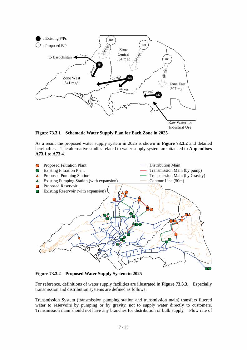
7 - 25
: Existing F/Ps
: Proposed F/P
250 m
gd
130
mgd
187
mgd
Zone West341 mgd
Zone Central
534 mgd
Zone East307 mgd
to Barochistan
Raw Water for Industrial Use
5 mgd
70 m
gd
21 mgd
404 mgd120 mgd
425
260
260
130
120
75
Figure 73.3.1 Schematic Water Supply Plan for Each Zone in 2025 As a result the proposed water supply system in 2025 is shown in Figure 73.3.2 and detailed hereinafter. The alternative studies related to water supply system are attached to Appendixes A73.1 to A73.4.
Distribution MainTransmission Main (by pump)Transmission Main (by Gravity)Contour Line (50m)
Proposed Filtration PlantExisting Filtration PlantProposed Pumping StationExisting Pumping Station (with expansion)Proposed ReservoirExisting Reservoir (with expansion)
Figure 73.3.2 Proposed Water Supply System in 2025 For reference, definitions of water supply facilities are illustrated in Figure 73.3.3. Especially transmission and distribution systems are defined as follows: Transmission System (transmission pumping station and transmission main) transfers filtered water to reservoirs by pumping or by gravity, not to supply water directly to customers. Transmission main should not have any branches for distribution or bulk supply. Flow rate of

7 - 26
the transmission system is equal to daily water demand. Distribution System (distribution pumping station, trunk distribution main and distribution network main) supplies filtered water from reservoirs to customers. The design capacity of distribution system is needed to be 1.5 – 2.0 times of daily water demand considering hourly demand fluctuation. For example, during the night people use less water, but in the morning and evening people use much more water.
Lagoon
M
P
P
M
M
M
M
M M
MM
M
M
M
MM
M M
FiltrationPlant
Bulk Water Canal/Conduit
Reservoir
ReservoirTransmissionPump
DistributionPump
Transmission
Main
TrunkDistribution
Main(by pump)
DistributionNetwork
Main
M
Bul
kR
etai
l
TrunkDistribution Main
TrunkDistribution Main
TrunkDistributionMainTrunk
DistributionMain
DistributionNetwork
Main
DistributionNetwork
Main
Bul
kR
etai
l
Flow Meter(District Meter)
TownBoundary
MM
Flow Meter(Sub-district Meter)
Figure 73.3.3 Typical Water Supply System 7.4 WATER SOURCES Table 74.1.1 summarises planned future water sources of the KW&SB’s water supply. Table 74.1.1 Water Sources for the Target Year of 2025
Water Source Capacity Remarks Kinjhar Lake (The Indus River) 645 mgd (1,200 cusecs; ft3/s) Existing Kinjhar Lake (The Indus River) 645 mgd (1,200 cusecs; ft3/s) Additional planned by K-IV Project Hub Dam 75 mgd Existing Dumlottee Wells 0 mgd To be abandoned
Total 1,365 mgd In addition to the current bulk water of 1,200 cusecs (645 mgd) from Kinjhar Lake, another 1,200 cusecs (645 mgd) will be also taken from Kinjhar Lake for 2025 by the implementation of K-IV Project. It is estimated that 75 mgd can be taken from Hub Dam at the probability of 95% based on a hydrologic analysis, for the KW&SB’s water supply including water supply to part of Barochistan District. For reference, flow data of the Indus River above the Kotri Barrage and withdrawals at the Kotri Barrage from 1976 to 1984 (Feasibility Study for future expansion of Karachi Water Supply System, December 1985) are attached to Appendix A32.1. On the other hand, existing Dumlottee Wells will not be suitable for the KW&SB’s water source

7 - 27
any more, since its production has been decreasing year by year. At present it is used only in a limited period of rainy season. CDGK have requested the Federal Government for granting an additional water right of 1,200 cusecs from Indus River for Karachi Water Supply System. As of the end of December 2007, however, an additional water right from the Indus River of 1,200 cusecs has not been approved yet. In developing a water supply system, Karachi would be granted additional 1,200 cusecs of quota from the Indus River and a total of 2,400 cusecs of the Indus River water would be made available at the Kinjhar Lake for abstraction of KW&SB. This is based on a strong belief that if this additional quota water were not granted, then there would be no such large population increase or significant developments in future as has been envisaged by KSDP – 2020 (August 2007). 7.5 BULK WATER SUPPLY SYSTEM 7.5.1 Existing Bulk Water Supply System Present bulk water supply system for Karachi City has a capacity of 600 mgd as shown in Table 75.1.1. This figure does not include bulk water supply of bulk water from Gujjo Headworks to Pakistan Steel Mills and Port Qasim Authority which have their own bulk water transmission facilities (canals and pumping stations) and filtration plants. Actually as of the end of year 2006 KW&SB supplied bulk water of about 630 mgd beyond the capacity as shown in Table 75.1.1 and detailed in Section 3.3.1. Figure 75.1.1 shows a schematic diagram of the existing bulk water supply system. Table 75.1.1 Bulk Water Supply Capacity
Bulk Water System Capacity Actual Supply GK System 280 mgd 300 mgd Haleji System 20 mgd 30 mgd K-II System 100 mgd 120 mgd K-III System 100 mgd 100 mgd Dumlottee Wells 20 mgd 0 mgd Hub System 80 mgd 80 mgd Total 600 mgd 630 mgd
source: KW&SB

7 - 28
Kotri Barrage
KB Feeder Upper
KG Canal
Gujjo Headworks
KB Feeder Lower
Gharo F/P
Kinjhar Lake
Hadero LakeHaleji Lake
Indu
s Riv
er
Hub Dam
Dhabeji Pumping Station
Fore Bay(high point)
Pipri F/P
COD F/P
NEK New F/P
NEK Old F/P
Hub F/P
Dumlottee Wells
DumlotteeConduit
HalejiConduit
GK/K-II/K-IIIConduit
GK/K-II/K-IIIConduit
Hub Main Canal
InterconnectingMain
LasbelaCanal
Karachi W/SCanal
N
S
EW
0 5 10 20 kmArabian Sea
LEGEND
Bulk Water Supply SystemFiltration Plant (F/P)Pumping Station
Figure 75.1.1 Existing Bulk Water Supply System 7.5.2 Proposed Bulk Water Supply System (1) Canal and Conduit Existing bulk water supply systems including GK, K-II and K-III bulk water supply systems will be continuously used for the future system. The existing bulk water supply system from Hub Dam to Manghopir Pumping Station (P/S) will be also used continuously. The periodical and proactive rehabilitation and repair works for the existing bulk water canals and conduits are proposed, since the existing bulk water canals and conduits are very old. It is also recommended that KW&SB should measure the actual flow rates of these canals and conduits for identifying current status of the bulk water supply system. As a result KW&SB may need to review and improve those capacities. On the other hand, Dumlottee Conduit will be abandoned by 2025 because of the permissible yield of the Dumlottee Wells. At present K-III system transfers bulk water to Manghopir P/S through K-III Pumping Station (P/S), NEK Old Reservoir and NEK-Hub Link Main for making up for the water shortage of Hub Dam. In the proposed system, water pumped up from K-III P/S will be filtered at new F/P (K-III F/P) near NEK Old F/P and then distributed to customers. Therefore, no water goes to Manghopir P/S from the K-III system. Figure 75.2.1 shows a proposed Greater Karachi Bulk Water Supply System from Kinjhar Lake to Karachi City considering actual bulk supply amount and on-going projects of the expansion of COD F/P and construction of K-III F/P which have been proposed by KW&SB by using ADB Loan. In addition to the existing bulk water supply system, three canals with a total capacity of 780 mgd (260 mgd × 3 canals) will be constructed by K-IV Project. Those canals will transfer bulk water from Kinjhar Lake to three filtration plants which will be also proposed by K-IV Project. The capacity of future bulk water supply system is summarised in Table 75.2.1. Figure 75.2.2 shows a proposed arrangement between bulk water canals and filtration plants which will be constructed by K-IV project.

7 - 29
Guj
jo H
eadw
orks
Hal
eji
Con
duit
Gha
ro F
/P:
20 m
gd
K-I
I Con
duit:
100
mgd
GK
Con
duit:
280
mgd
K-I
II C
ondu
it: 1
00 m
gdD
habe
ji Pu
mpi
ng
Stat
ion
Fore
Bay
(h
igh
poin
t)
Pipr
i (O
ld)
F/P:
50
mgd
NEK
New
F/P
: 10
0 m
gd
NEK
Old
F/P
: 25
mgd
Bul
k W
ater
to
PSM
& P
QA
32 m
gd
KG
Can
al
20 m
gd30
5 m
gd
120
mgd
100
mgd
O
50 mgd
4
30 mgd
20 mgd
Pipr
i (N
ew)
F/P:
50
mgd
A
20 m
gd22
5 m
gd
100
mgd
100
mgd
225
mgd
100
mgd
100
mgd
K-I
I Con
duit
GK
Con
duit
K-I
II C
ondu
it
K-I
I Con
duit
GK
Con
duit
K-I
II C
ondu
it
84"
Pipe
25 mgd
100 mgd20
0 m
gd
85 m
gd
70 m
gd
45 m
gdC
OD
(New
) F/
P: 4
5 m
gd
CO
D (O
ld)
F/P:
70
mgd
CO
D R
eser
voir
NEK
Old
R
eser
voir
Pipr
i Res
ervo
ir
Kin
jhar
Lak
e
In
dus R
iver
KB
Fee
der U
pper
Kot
ri B
arra
ge A
ppor
tionm
ent f
or K
arac
hi W
ater
Sup
ply:
645
mgd
LEG
END Ex
istin
g Fi
ltrat
ion
Plan
tPr
opos
ed F
iltra
tion
Plan
tPu
mpi
ng S
tatio
nR
eser
voir
CO
D (P
ropo
sed)
F/
P: 8
5 m
gd
K-I
II (P
ropo
sed)
F/
P: 1
00 m
gd
525
mgd
545
mgd
577
mgd
Figure 75.2.1 Future Greater Karachi Bulk Water Supply System

7 - 30
Table 75.2.1 Future Bulk Water Supply Capacity Bulk Water System Existing Capacity Future Capacity Remarks
GK System 280 mgd 305 mgd Existing Haleji System 20 mgd 20 mgd Existing K-II System 100 mgd 120 mgd Existing K-III System 100 mgd 100 mgd Existing Dumlottee Wells 20 mgd 0 mgd to be abandonedHub System* 80 mgd 75 mgd Existing K-IV System - 780 mgd Proposed Total 600 mgd 1,400 mgd
source: KW&SB * : considered to “95% level of reliability of the Hub River Yield”
Central
260 mgd Canal
130
mgd
F/P
Stage I for the year 2016 (constructed from 2009 to 2011)
CentralWest East
260 mgd Canal
130
mgd
F/P
Stage II for the year 2021 (constructed from 20014 to 2016)
CentralWest East
260 mgd Canal
130
mgd
F/P
Stage III for the year 2025 (constructed from 2019 to 2021)
130
mgd
F/P
130
mgd
F/P
Figure 75.2.2 Proposed Arrangement between Canals and Filtration Plants constructed by K-IV Project

7 - 31
(2) Bulk Transmission Pumping Station The bulk transmission pumping stations for the target year of 2025 which are used mainly as intake pumping station at filtration plants except Dhabeji P/S are listed in Table 75.2.2. The life span of the pumping equipment is assumed to be 15 years. Therefore, the pumping equipment in all the existing pumping stations should be replaced by 2025. Among the KW&SB’s facilities, NEK Old Pumping House near NEK New F/P is well maintained and operated. Mechanical and electrical equipment at this pumping house is being kept in good condition. This is able to become a model for others to emulate for operation and maintenance of mechanical and electrical equipment not only at other P/Ss but also at F/Ps. Table 75.2.2 Bulk Transmission Pumping Stations in 2025
Generator
1 Dhabeji (Phase-I) 1959 120 48 5 3 24 210 Diesel+Gas 0.25
2 Dhabeji (Phase-II) 1971 125 100 5 1 25 210 1050 --
3 Dhabeji (Phase-III) 1978 125 100 5 1 25 210 1050 --
4 Dhabeji (Phase-IV) 1997 125 100 5 1 25 210 1050 4.52
5 K-II (Dhabeji) 1998 175 140 5 1 35 210 1635 --
6 K-III (Dhabeji) 2006 210 140 6 2 35 210 1635 --
7 Gharo (Old) 1943 37 23 3 1 5 170 Diesel 0.5
1982 6 2 2.0 170 74.6
2002 2 1 5.0 170 149.1
8 Gharo (New) 1953 40 21 2 1 10 170 Diesel 0.5
1997 5 2 2.0 170 93.2
2002 2 1 5.0 170 186.4
9 Pipri (old) 1971 75 50 6 2 12.5 100 260 1.5
10 Pipri (Phase IV) 1994 50 37.5 4 1 12.5 56 132 1.25
11 Pipri (New) 2000 60.48 51.84 14 2 4.32 100 111.9 0.6
12 Hub (New) 2006 175 105 4 1 35 168 1350 -
(Manghopir) 2 2 17.5 168 750
13 NEK (Old) 1978 80 35 4 2 12.5 160 372.9 1.25
6 4 5 160 111.9
14 Low Lift (at NEK New) 1998 175 105 5 2 35 40 232.7 -
15 K-III (at NEK New) 2006 135 90 6 2 22.5 160 391.5 -
Name of Pumping StationSr.No. Capacity(MW)
Pump Head (ft) Electric Motor(KW)
Year ofConstruction
Total Capacity(MGD)
Pumps & Motors
No, ofStand-By
Pumps
Total No.of Pumps
Capacity ofEach Pump
(MGD)
RunningCapacity(MGD)
In addition to the existing bulk pumping stations, two bulk pumping stations between Kinjhar Lake and Filtration Plants are proposed for new bulk water transmission system to be constructed by K-IV Project. Details of new pumping stations are summarised in Table 75.2.3. Table 75.2.3 Details of New Bulk Pumping Station
Pumping Station Stage Capacity Total Dynamic Head (m)
Power Plant Required (MW)
Stage I 130 mgd 41 3.9 Stage II 260 mgd 41 7.8 1st Stage Pumping Station Stage III 260 mgd 41 7.8 Stage I 130 mgd 74 7.1 Stage II 260 mgd 74 14.2 2nd Stage Pumping
Station Stage III 260 mgd 74 14.2
source: K-IV Project, Greater Karachi Water Supply Scheme (Executive Summary, May 2007) On the other hand, the study proposes that the following seven existing bulk pumping stations are eliminated for future bulk water supply system for energy cost saving.
• 9th Mile Pumping Station • Low Service Reservoir Old Pumping Station

7 - 32
• Low Service Reservoir New Pumping Station • Ajmer Nagri Pumping Station • Temple and Currie Pumping Station • Dumlottee Pumping Station • Board Office Pumping Station
7.6 WATER FILTRATION PLANTS 7.6.1 Proposed Filtration Plants Table 76.1.1 shows a list of zone-wise filtration plants (F/Ps) proposed in 2025. Production of all the F/Ps is expected to keep their design capacities without overload operation. Table 76.1.1 Filtration Plants in 2025
Filtration Plant Zone Capacity (mgd) Remarks
Hub F/P West 75 Existing West F/P West 260 proposed by K-IV Project Sub-Total of Zone West 335 NEK Old F/P Central 25 Existing NEK New F/P Central 100 Existing COD F/P Central 115 Existing Central 85 expansion by ADB Project KIII F/P Central 100 proposed by ADB Project Central F/P Central 130 proposed by K-IV Project Sub-Total of Zone Central 555 Gharo F/P East 20 Existing Pipri F/P East 100 Existing East F/P East 260 proposed by K-IV Project Sub-Total of Zone East 380 Total 1,270
At present water for K-III F/P and COD F/P to be expanded is supplied directly to customers without filtration. It is, therefore, recommended that such water should be treated at filtration plant. Asian Development Bank proposes the construction of K-III F/P and expansion of COD F/P (Draft Karachi Sustainable Mega City Water and Wastewater Roadmap, May 2007, ADB). K-III F/P with a capacity of 100 mgd will be constructed at/near the site of NEK Old F/P and COD F/P with a capacity of 85 mgd will be expanded at the existing COD F/P. It is, however, noted that the construction of K-III F/P (100 mgd) and the expansion of COD F/P (85 mgd) are not the increase of water supply capacity because water of 100 mgd for K-III F/P and 85 mgd for COD expansion is being supplied directly to customers without filtration. New F/Ps (260 mgd × 2 plants at Zone West and Zone East and 130 mgd × 1 plant at Zone Central) are proposed for future water supply system. As described in Section 7.3 “System Development Plan”, West F/P, Central F/P and East F/P are expected to start its production by year 2016, 2011 and 2016 respectively. New F/Ps will consist of large capacity lagoon (520 mg) for storing 2 days bulk (raw) water and for grit chamber in case of coming turbid water from the Kinjhar Lake (K-IV Project, Greater Karachi Water Supply Scheme, Executive Summary, May 2007). As well as the existing process, the rapid sand filtration system is recommended for the proposed treatment process. The proposed treatment process consists of receiving chamber, sand filtration and chlorination and is shown in Figure 76.1.1. This process was designed with consideration of the bulk water quality (see Table 76.1.2) and the existing process. In addition the space for rapid mixing basin and flocculation/sedimentation basin should be kept for future treatment process

7 - 33
due to deterioration of bulk water quality. If the turbidity is found as high level continuously, it is recommended constructing rapid mixing basin and flocculation/sedimentation basin as pre-treatment to remove turbidity.
Lagoon Receiving Chamber Sand FilterKinjhar
Lake
Transmission/Distribution
Chlorine
Clear Water Reservoir
Chlorine
Figure 76.1.1 Proposed Water Treatment Process for New Filtration Plant Table 76.1.2 Bulk Water Quality of KG Canal before Gujjo Headworks
Parameters Unit Dry Season (June 2006)
Wet Season (August 2006)
pH 8.20 8.11 Turbidity NTU 0.19 0.55 Iron mg/l 0.11 0.165 Manganese μg/L 7.40 10.81 Ammonia-Nitrogen mg/l 0.096 ND Faecal Coliform count/dl 43 1,100
source: Progress Report No.1, September 2006 7.6.2 Rehabilitation and Improvement of Existing Filtration Plants The design life for the filtration plants is generally shown in Table 76.2.1. The design life for concrete structures is 50 years and the design life for mechanical and electrical equipment is 15 years. Once the design life is exceeded, the facilities will be abandoned and new facilities will be constructed, if necessary. Table 76.2.1 Design Life for the Filtration Plants
Intake Facilities Life Time (years) Pump House (concrete structure) 50 Mechanical and electrical equipments 15 Filtration Plant Tank and basin (concrete structures) 50 Mechanical and electrical equipments 15
At present (as of 2007) KW&SB are proposing PC1 for the rehabilitations of the existing plants including Gharo F/P, Pipri (old 25 mgd × 2 plants) F/P, COD F/P and NEK Old F/P. The rehabilitations to the existing plants should include not only repair of the existing facilities and equipment but also some improvements based on plant safety, process control, and the need for continuous water supply. Plant safety is the most important aspect of the proposed improvements. Most filtration plants do not have safety measurement equipment for chlorine gas and some plants do not use a chlorinator for chlorination. Therefore safety and health improvements have been set as the highest priority. Process control improvements such as installing flow meters are set as the second priority. Therefore the rehabilitation and improvement of the existing filtration plants include, but are not limited to;
• Replacement of a top layer of filter media • Rehabilitation of all valves, fittings and other accessories for filter basin • Rehabilitation of backwashing system for filter basin • Replacement of chlorinators and accessories and improvement of safety measurement
equipment for chlorination system

7 - 34
• Replacement and repair of chemical dozing equipment including pipelines and other accessories
• Installation of level indicators at reservoirs • Installation of flow meters at outlet of reservoirs • Rehabilitation of standby generating set • Repair of steel structure • Repair of leakages from the water retaining structures and pipelines • Repair and replacement of damaged flooring, walls, doors and windows where ever
required. • Arrangement of lighting system for security along the boundary line
Other F/Ps of NEK New F/P, Hub F/P and Pipri (new 50 mgd plant) are recommended to be rehabilitated at Stage III from 2019 to 2021. 7.7 WATER TRANSMISSION SYSTEM 7.7.1 General Existing water transmission system will be improved by dividing water supply areas of Karachi into three zones of Zone-West, Zone-Central, and Zone-East. The estimated zone-wise demands in 2016, 2021, and 2025 are shown in Tables 77.1.1 and 77.1.2. The future land use map in 2025 including future roads proposed in Karachi Strategic Development Plan 2020 (Final, August 2007) is shown in Figure 77.1.1. A contour map of Karachi is generated using GIS software from Digital Elevation Model developed based on 1:50,000 topographic maps prepared by Survey of Pakistan during 1991~1995. The created contour map is shown in Figure 77.1.2. Based on these basic conditions and information, new filtered water transmission system including trunk distribution mains for the three zones is proposed as seen in Figure 77.1.3 in consideration of;
• eliminating the use of several bulk pumping stations and a large number of small size distribution pumping stations for energy cost saving,
• supplying water by gravity as much as possible, and • keeping minimum dynamic water pressure of 10 m in distribution system.
Flow diagram of the proposed system in 2025 is shown in Figure 77.1.4. Flow diagrams of the proposed systems for intermediate years of 2016 and 2021 are attached to Appendix 77.1. As the result of a preliminary hydraulic analysis, pumping will be required only for transferring water from filtration plants to the distribution reservoirs in order to supply water to relatively high altitude area. The details of proposed reservoirs, filtered water transmission mains, transmission pump stations and network analysis are further explained in the following sub-sections.

7 - 35
Table 77.1.1 Zone-Wise Water Demand (1/2) Zone-Wise Water Demand in 2011Zone-West Zone-Central Zone-East
DemandTown Town Town
1 Keamari (West) 17.64 mgd 3 Keamari (Port) 10.20 mgd 10 Landhi 38.56 mgd2 SITE 34.56 mgd 5 Lyari 22.65 mgd 11 Korangi 37.70 mgd3 Baldia 18.59 mgd 6 Saddar 70.72 mgd 17 Bin Qasim 64.52 mgd4 Orangi 28.00 mgd 7 Jamshed 36.86 mgd 18 Gadap (East) 3.78 mgd
12 North Nazimabad 26.34 mgd 8 Gulshan-e-Ibal 60.92 mgd13 New Karachi 26.11 mgd 9 Shah Faisal 23.40 mgd14 Gulberg 23.47 mgd 16 Malir 40.46 mgd15 Liaquatabad 29.43 mgd 18 Gadap (Central) 22.64 mgd18 Gadap (West) 12.87 mgd
Canttonment Canttonment Canttonment① Manora 0.39 mgd ⑥ Korangi 3.60 mgd② Malir 15.27 mgd③ Karachi 1.00 mgd④ Crifton 0.89 mgd⑤ Faisal 6.88 mgd
Other Authority Other Authority Other AuthorityDHA 25.88 mgd
Other District Other District Other DistrictBarochistan 5 mgd Thatta (as Low Water)
Total Demand 222.01 mgd Total Demand 338.16 mgd Total Demand 148.16 mgd
Grand Total of Demand 708.33 mgd
ProductionFP FP FP
Hub 80 mgd NEK Old 25 mgd Gharo 20 mgdNEK New 100 mgd Pipri 100 mgdCOD 115 mgdK-III 100 mgd
Total Production 80 mgd Total Production 340 mgd Total Production 120 mgd
Grand Total of Production 540 mgd
Remainded Production -142.01 mgd Remainded Production 1.84 mgd Remainded Production -28.16 mgd
Zone-Wise Water Demand in 2016Zone-West Zone-Central Zone-East
DemandTown Town Town
1 Keamari (West) 32.34 mgd 3 Keamari (Port) 11.83 mgd 10 Landhi 45.36 mgd2 SITE 36.36 mgd 5 Lyari 23.06 mgd 11 Korangi 46.59 mgd3 Baldia 25.63 mgd 6 Saddar 71.68 mgd 17 Bin Qasim 94.79 mgd4 Orangi 31.06 mgd 7 Jamshed 43.79 mgd 18 Gadap (East) 6.68 mgd
12 North Nazimabad 28.71 mgd 8 Gulshan-e-Ibal 79.66 mgd13 New Karachi 27.88 mgd 9 Shah Faisal 24.38 mgd14 Gulberg 25.83 mgd 16 Malir 43.19 mgd15 Liaquatabad 29.42 mgd 18 Gadap (Central) 42.95 mgd18 Gadap (West) 21.76 mgd
Canttonment Canttonment Canttonment① Manora 0.47 mgd ⑥ Korangi 4.36 mgd② Malir 18.52 mgd③ Karachi 1.21 mgd④ Crifton 1.07 mgd⑤ Faisal 8.34 mgd
Other Authority Other Authority Other AuthorityDHA 30.73 mgd
Other District Other District Other DistrictBarochistan 5 mgd Thatta (as Low Water)
Total Demand 263.98 mgd Total Demand 400.88 mgd Total Demand 197.77 mgd
Grand Total of Demand 862.64 mgd
ProductionFP FP FP
Hub 75 mgd NEK Old 25 mgd Gharo 20 mgdNEK New 100 mgd Pipri 100 mgdCOD 200 mgdK-III 100 mgdCentral 130 mgd
Total Production 75 mgd Total Production 555 mgd Total Production 120 mgd
Grand Total of Production 750 mgd
Remainded Production -188.98 mgd Remainded Production 154.12 mgd Remainded Production -77.77 mgd

7 - 36
Table 77.1.2 Zone-Wise Water Demand (2/2) Zone-Wise Water Demand in 2021Zone-West Zone-Central Zone-East
DemandTown Town Town
1 Keamari (West) 47.69 mgd 3 Keamari (Port) 12.52 mgd 10 Landhi 54.75 mgd2 SITE 38.83 mgd 5 Lyari 23.87 mgd 11 Korangi 58.61 mgd3 Baldia 31.11 mgd 6 Saddar 74.53 mgd 17 Bin Qasim 129.36 mgd4 Orangi 34.76 mgd 7 Jamshed 50.03 mgd 18 Gadap (East) 10.03 mgd
12 North Nazimabad 32.13 mgd 8 Gulshan-e-Ibal 103.06 mgd13 New Karachi 30.36 mgd 9 Shah Faisal 25.79 mgd14 Gulberg 28.88 mgd 16 Malir 48.11 mgd15 Liaquatabad 30.53 mgd 18 Gadap (Central) 64.06 mgd18 Gadap (West) 30.21 mgd
Canttonment Canttonment Canttonment① Manora 0.57 mgd ⑥ Korangi 5.27 mgd② Malir 22.37 mgd③ Karachi 1.46 mgd④ Crifton 1.30 mgd⑤ Faisal 10.07 mgd
Other Authority Other Authority Other AuthorityDHA 37.64 mgd
Other District Other District Other DistrictBarochistan 5 mgd Thatta (as Low Water)
Total Demand 309.50 mgd Total Demand 475.36 mgd Total Demand 258.01 mgd
Grand Total of Demand 1,042.87 mgd
ProductionFP FP FP
Hub 80 mgd NEK Old 25 mgd Gharo 20 mgdWest 130 mgd NEK New 100 mgd Pipri 100 mgd
COD 200 mgd East 130 mgdK-III 100 mgdCentral 130 mgd
Total Production 210 mgd Total Production 555 mgd Total Production 250 mgd
Grand Total of Production 1,015 mgd
Remainded Production -99.50 mgd Remainded Production 79.64 mgd Remainded Production -8.01 mgd
Zone-Wise Water Demand in 2025Zone-West Zone-Central Zone-East
DemandTown Town Town
1 Keamari (West) 60.22 mgd 3 Keamari (Port) 13.09 mgd 10 Landhi 62.40 mgd2 SITE 40.79 mgd 5 Lyari 24.59 mgd 11 Korangi 68.30 mgd3 Baldia 35.63 mgd 6 Saddar 76.71 mgd 17 Bin Qasim 155.34 mgd4 Orangi 37.91 mgd 7 Jamshed 55.27 mgd 18 Gadap (East) 14.53 mgd
12 North Nazimabad 35.03 mgd 8 Gulshan-e-Ibal 121.99 mgd13 New Karachi 32.47 mgd 9 Shah Faisal 26.93 mgd14 Gulberg 31.48 mgd 16 Malir 51.84 mgd15 Liaquatabad 31.51 mgd 18 Gadap (Central) 79.84 mgd18 Gadap (West) 36.22 mgd
Canttonment Canttonment Canttonment① Manora 0.65 mgd ⑥ Korangi 5.97 mgd② Malir 25.33 mgd③ Karachi 1.66 mgd④ Crifton 1.47 mgd⑤ Faisal 11.41 mgd
Other Authority Other Authority Other AuthorityDHA 43.48 mgd
Other District Other District Other DistrictBarochistan 5 mgd Thatta (as Low Water)
Total Demand 346.27 mgd Total Demand 534.25 mgd Total Demand 306.54 mgd
Grand Total of Demand 1,187.05 mgd
ProductionF/P F/P F/P
Hub 75 mgd NEK Old 25 mgd Gharo 20 mgdWest 260 mgd NEK New 100 mgd Pipri 100 mgd
COD 200 mgd East 260 mgdK-III 100 mgdCentral 130 mgd
Total Production 335 mgd Total Production 555 mgd Total Production 380 mgd
Grand Total of Production 1,270 mgd
Remainded Production -11.27 mgd Remainded Production 20.75 mgd Remainded Production 73.46 mgd

7 - 37
source: Karachi Strategic Development Plan 2020 (Final, August 2007) Figure 77.1.1 Future Land Use in 2025 Figure 77.1.2 Karachi Contour Map
Karachi Land Use Plan -2020
Karachi Contour Map
50m
150m
100m
0m

7 - 38
Figure 77.1.3 Proposed Water Supply System in 2025

7 - 39
Figure 77.1.4 Flow Diagram of Proposed System in 2025

7 - 40
7.7.2 Network Analysis (1) Conditions of Network Analysis 1) Formula for Hydraulic Calculation: Hazen-Williams Formula There are a number of formulae available to calculate the velocity of flow (e.g. Hazen-Williams formula, Manning’s formula, Darcy-Weisbach’s formula and Colebrook-White formula). The Hazen-Williams formula is the best for situations involving pressure conduits. The formula is: V = 0.84935 C R0.63 I0.54 For circular conduits, the formula is restated as hf = 10.666 C-1.85 D-4.87 Q1.85 L Where, V = Velocity (m/s) C = Hazen-Williams coefficient R = Hydraulic Radius (m) I = Hydraulic Gradient, hf/L hf = Friction Head Loss (m) D = Diameter of Pipe (m) Q = Discharge (m3/s) L = Pipe Length (m) For confirmation, Darcy-Weisbach’s formula with a friction factor of e=0.45mm which is calculated with Colebrook-White formula was also used for checking hydraulic analysis. There was no much difference between the results. Therefore, the Hazen-Williams formula has been adopted for this study. 2) Hazen-Williams Coefficient (C Value): 110 for all materials The Hazen-Williams coefficient (C value) for new pipes made from cast iron, ductile iron or mild steel with cement mortar lining may be between 130 and 145. However, it is generally recommended that in the absence of specific data, a C value of 110 should be adopted. Therefore, a C value of 110 was adopted when designing the transmission and distribution system, including the existing pipelines. 3) Hourly Peak Factor: 1.5 When designing the distribution system hourly demand fluctuations must be considered. For example, during the night people use less water, but in the morning and evening people use much more water. Because of absence of flow data for determining current hourly peak factor in Karachi, a peak factor of 1.5 was adopted referring to “Feasibility Study for future expansion of Karachi Water Supply System, December 1985”. It is, however, difficult to review the time factor of 1.5 because water flow has not been measured properly. 4) Minimum Dynamic Water Pressure: 10 m A minimum pressure of 10 m in the distribution system has been adopted under peak flow conditions. This will provide sufficient pressure for 2 or 3 storey house. 5) Details of the Existing Water Supply System It should be noted that since there is no recorded data or drawings of the existing transmission and distribution systems or details of the reservoirs, the modelling for the hydraulic analysis was prepared based on interviews with the KW&SB’s engineers, for the followings system components:
• routes, materials and diameters of transmission and trunk distribution mains; and • locations, capacities and water level of reservoirs.
(2) Results of Network Analysis Appendix A77.1 shows the results of the analysis in detail.

7 - 41
7.7.3 Transmission Pumping Stations Proposed transmission pump stations will deliver filtered water to distribution reservoirs through transmission mains for supplying water mainly to new developing area of three fringe towns, Keamari, Bin Qasim and Gadap. These areas are relatively high altitude area where is higher than the filtration plant or almost the same altitude as the filtration plant. The proposed pumping stations for the target year of 2025 including two existing pumping stations (Manghopir PS and High Lift PS) are shown in Table 77.3.1. Table 77.3.1 Proposed Transmission Pumping Station in 2025
Pump Head2016 2021 2025 (m)
West TPS-W-Mangopir 40.98 52.53 58.48 60TPS-W-West - 6.69 22.07 50
Central TPS-C-COD 26.06 29.76 32.89 20Transmission TPS-C-NEK New 18.65 0.00 0.00 40Pumping TPS-C-Central 24.41 47.48 73.50 30Station TPS-C-High_Lift 75.91 83.97 90.17 25
East TPS-E-East-01 - 28.67 36.93 40TPS-E-East-02 - - 13.08 50TPS-E-E02 - - 6.54 40
Q (mgd)Type Zone Name
7.7.4 Water Transmission Mains (1) Proposed Water Transmission Mains The dimensions of proposed water transmission mains are listed in Table 77.4.1. Figure 77.1.3 and Figure 77.1.4 include the routes and flow diagram of the proposed filtered water transmission system respectively. Proposed filtered water transmission mains should not have any branches for distribution or bulk supply. Routes of transmission mains pass through mainly new developing area of three fringe towns, Keamari, Bin Qasim and Gadap. For future system, the existing water trunk mains except the trunk mains between NEK New F/P and University Reservoir and NEK Old and Manghopir P/S (NEK Hub Main) will not be used as the water transmission mains, but utilised for the trunk distribution mains. However, the water trunk mains between NEK New F/P and University Reservoir (about 16.7 km in total) are proposed to be rehabilitated and replaced, which are included in Table 77.4.1. Table 77.4.1 Proposed Water Transmission Mains in 2025
Zone Year Dia. (in) Length (m)West 2016 72 141
Sub-Total 1412021 36 20,364
44 2,448Sub-Total 22,812
2025 100 37,390Sub-Total 37,390
60,343Central 2016 48 5,425
56 11,34864 22,70088 9,275
Sub-Total 48,74848,748
East 2021 56 9,651100 20,364
Sub-Total 30,0152025 24 2,078
32 4,157Sub-Total 6,235
36,250145,341
Zone-Total
Zone-Total
Zone-Total
Total

7 - 42
(2) Water Management between Zones Considering water demands in three zones, some water should be managed across zone boundaries as shown in Figure 77.4.1. Some water should be supplied from Zone Central to Zone West because Zone Central has enough supply capacity for its demand. On the other hand, there is no water exchange between Zone Central and Zone East.
Zone West Zone Central Zone East
174 mgd
84 mgd
21 mgd
Year 2016
Year 2021
Year 2025
Figure 77.4.1 Water Management between Zones 7.7.5 Distribution Reservoirs (1) Proposed Distribution Reservoirs Distribution reservoirs should have enough capacity to cope with water demand fluctuation in a day. In general peaks in water demand appear in the morning, at noon and in the evening. However, hourly demand fluctuation is difficult to accurately quantify because the metering system does not exist in the current system. Based on engineering experiences, the capacity of distribution reservoir is proposed to be eight hours of daily demand. Distribution reservoirs should be located at suitable place to supply water with enough pressure of minimum 10 kgf/cm2 at the end of distribution network. To monitor and control the flow, flow meters and flow control valves should be installed at the outlet pipes at the reservoirs. And chlorination equipment should be installed in the all distribution reservoirs to increase the safety of water supply. Proposed reservoirs for 2025 are listed in the Table 77.5.1 and supply areas of each reservoir are shown in Figure.77.5.1. Table 77.5.1 Proposed Distribution Reservoirs in 2025
HWL LWL H Existing(+m) (+m) (m) 2016 2021 2025 (mg) 2016 2021 2025 2016 2021 2025
West Hub +103.63 +99.36 4.27 42.0 45.9 47.9 15.0 48.0 48.0 48.0 33.0 0.0 0.0Orangi +76.20 +71.32 4.88 0.0 0.0 20.1 6.0 0.0 0.0 20.0 0.0 0.0 20.0West* +95.00 +90.00 5.00 0.0 51.7 65.7 0.0 0.0 50.0 70.0 0.0 50.0 20.0W01* +125.00 +120.00 5.00 0.0 2.3 7.4 0.0 0.0 2.5 7.5 0.0 2.5 5.0Mangopir PS** +64.00 +61.00 3.00 0.9 1.1 1.2 0.0 1.5 1.5 1.5 1.5 0.0 0.0
Centarl COD +45.72 +40.23 5.49 32.0 32.0 32.0 16.0 32.0 32.0 32.0 16.0 0.0 0.0NEK Old +79.25 +74.37 4.88 76.5 57.1 61.5 10.0 76.5 76.5 76.5 66.5 0.0 0.0NEK New +56.39 +51.51 4.88 45.6 45.6 45.6 10.0 46.0 46.0 46.0 36.0 0.0 0.0University +67.06 +62.18 4.88 25.4 28.0 30.1 10.0 30.0 30.0 30.0 20.0 0.0 0.0High Service +45.72 +40.84 4.88 8.7 9.9 11.0 20.0 11.0 11.0 11.0 0.0 0.0 0.0Central* +95.00 +90.00 5.00 11.4 11.9 12.4 0.0 12.5 12.5 12.5 12.5 0.0 0.0C01* +110.00 +105.00 5.00 8.2 15.9 24.6 0.0 10.0 15.0 25.0 10.0 5.0 10.0
East Gharo +47.24 +45.72 1.52 6.7 6.7 6.7 6.0 8.0 8.0 8.0 2.0 0.0 0.0Pipri +76.20 +71.32 4.88 33.3 66.8 78.5 16.0 35.0 70.0 80.0 19.0 35.0 10.0East* +95.00 +90.00 5.00 0.0 11.9 23.2 0.0 0.0 12.0 24.0 0.0 12.0 12.0E01* +115.00 +110.00 5.00 0.0 9.6 12.4 0.0 0.0 12.5 12.5 0.0 12.5 0.0E02* +125.00 +120.00 5.00 0.0 0.0 2.4 0.0 0.0 0.0 2.5 0.0 0.0 2.5E03* +150.00 +145.00 5.00 0.0 0.0 2.2 0.0 0.0 0.0 2.5 0.0 0.0 2.5
Planned Total V (mg) Planned New V (mg)Zone Res Req. Total V (mg)
*: new reservoirs **: suction well for PS

7 - 43
Figure 77.5.1 Proposed Supply Area from Each Reservoir in 2025

7 - 44
(2) Rehabilitation of the Existing Reservoirs The Karachi Water Supply System has 16 existing distribution reservoirs including reservoirs at filtration plants, as listed in Table 77.5.2. Since the design life of the concrete structure is 50 years, this master plan proposes that 8 existing reservoirs constructed before 1975 will be rehabilitated by 2025. On the other hand, 4 reservoirs will be eliminated for future water supply system, since water from these reservoirs should be supplied by using distribution pumps. The area presently supplied from these reservoirs to be eliminated will be covered by other reservoirs by gravity. KW&SB are preparing to rehabilitate two reservoirs, High Service Reservoir and Orangi Reservoir. Especially, Orangi Reservoir is needed to be reconstruct at the existing site, since the existing reservoir has been destroyed. Table 77.5.2 List of Existing Reservoirs
Name of Exiting Reservoirs Construction Year*
Need for Rehabilitation
Elimination by 2025
Need for Expansion
Gharo F/P (Plant-1) 1942 × - × Pipri F/P (Plant-1) 1968 × - Pipri F/P (Plant-2) 1971 × - ×
NEK Old F/P 1980 - - × NEK New F/P 1998 - - × COD F/P (Plant-1) 1962 × - COD F/P (Plant-2) 1971 × - ×
Hub F/P 1982 - - × University 1971 × - × High Service 1945 × - - Low Service 1942 - × - Temple 1880 - × - Currie 1896 - × - Sydenham 1942 - × - Orangi 1982 × - × Kidney Hill 1978 - - -
*: information from KW&SB 7.7.6 Distribution Pumping Stations In the areas where water can not be supplied by gravity flow, water should be supplied by pumping from distribution reservoirs. The capacity of distribution pumps is needed to be 1.5 times of daily demand considering the time factor of demand fluctuation. Proposed distribution pumping stations will deliver water to customers who inhabit mainly at new developing area of three fringe towns, Keamari, Bin Qasim and Gadap. These areas are relatively high altitude area where is higher than the filtration plant or almost the same altitude as the filtration plant. The proposed pumping stations for the target year of 2025 are shown in Table 77.6.1. Table 77.6.1 Proposed Distribution Pumping Station in 2025
Pump Head2016 2021 2025 2016 2021 2025 (m)
Distribution West DPS-W-Orangi-Keamari - - 19.5 - - 29.3 50Pumping Central DPS-C-C01 - - 21.76 - - 32.6 50Station East DPS-E-E03 - - 5.01 - - 7.5 90
Ave. Q (mgd) Max. Q (mgd)Type Zone Name
On the other hand, a large number of the existing small size distribution pumping stations will be abandoned in the future system.

7 - 45
7.7.7 District Meter In order to improve the efficiency of transmission and distribution system and to supply water equitably to the service area, it is necessary to understand how much water is flowed into which area. For that purpose, installation of flow meters (district meters) for transmission mains and trunk distribution mains is proposed mainly at the following locations. The number of flow meters required for the system in 2025 is listed in Table 77.7.1.
• Outlet of filtration plants, pumping stations and reservoirs • Downstream of branch points of transmission and trunk distribution mains • Boundary of towns
Table 77.7.1 Proposed District Flow Meters
West Central East Sub-Total West Central East Sub-Total12 0 4 1 5 514 0 3 15 3 21 2116 0 1 4 5 518 0 5 8 2 15 1520 0 1 1 124 2 2 11 21 3 35 3728 0 2 2 4 432 2 2 7 10 3 20 2236 2 2 4 4 1 9 1148 3 3 11 14 3 28 3154 0 1 2 3 356 6 2 8 1 5 2 8 1660 0 1 1 164 2 2 2 2 466 0 2 1 3 372 3 3 2 3 1 6 980 0 4 4 488 2 2 2 1 4 7 9100 2 2 4 1 5 6 10
Total 7 13 8 28 53 103 27 183 211
TotalDiameter(in)
Transmission Mains Distribution Mains
7.8 DISTRUBUTION NETWORK AND SERVICE CONNECTION 7.8.1 Proposed Distribution Network and Service Connection (1) Trunk Distribution Mains The existing water trunk mains as listed in Table 78.1.1 are proposed to be used as trunk distribution mains for future water supply system, except the trunk mains between NEK New F/P and University Reservoir and NEK Old and Manghopir P/S (NEK Hub Main) which will be used as the water transmission mains. At present KW&SB use these water trunk mains mainly as transmission mains from filtration plants to reservoirs or trunk distribution mains. In future proposed system these water trunk mains will be mainly used as trunk distribution mains from reservoirs, since they already have many brunch connections. In addition some large diameter’s pipelines of the existing distribution pipes shown in Table 78.1.2 will be used as the trunk distribution mains.

7 - 46
Table 78.1.1 Existing Water Trunk Mains Diameter Length
in mm (m) 12 300 5,720 15 375 4,266 18 450 36,106 24 600 72,268 32 800 27 33 825 77,235 36 900 15,311 40 1,000 2,644 42 1,050 2,631 48 1,200 88,113 54 1,350 39,667 64 1,600 6,112 66 1,650 30,960 72 1,800 13,693 84 2,100 10,409
Total 405,163 *Source: KW&SB Table 78.1.2 Existing Distribution Pipes
Diameter Length in mm (km)
3 75 1,636.2 4 100 1,531.9 5 125 60.0 6 150 609.0 8 200 199.0 9 225 34.6
10 250 130.6 12 300 317.0 15 375 107.1 16 400 20.1 18 450 96.8 21 525 1.0 24 600 58.1 27 675 5.2 30 750 2.5 33 825 25.2 36 900 6.3 48 1,200 8.9 54 1,350 3.0 60 1,500 2.0
Total 4,854.4 *Source: KW&SB The proportions of PRCC pipes used in the existing water trunk mains are more than 80 %. Therefore the study recommend that the existing trunk mains to be used as the trunk distribution mains are replaced with steel pipes or ductile cast iron pipes for future system. Because in general steel pipes and ductile cast iron pipes are widely used for pressured and treated water pipeline of large diameters (300 mm and more) in other countries. PRCC has disadvantages of workability, difficulty of field modifications due to differing site conditions and difficulty of repairs for leakages and damages. Total length of trunk distribution mains required for future water supply system in 2025 is about 1,600 km as listed in Tables 78.1.3 and 78.1.4 including about 685 km of the existing water trunk mains and parts of large diameters of distribution mains.

7 - 47
Table 78.1.3 Proposed Trunk Distribution Mains (1/2) Zone Supply Area Type Year Dia. (in) Length (m) Zone Supply Area Type Year Dia. (in) Length (m)
West HUB Replacement 2016 14 11,321 West Replacement 12 5,680of 16 9,949 of 14 24,735
Existing Pipeline 18 15,563 Existing Pipeline 16 14,91424 20,925 18 62,35332 26,626 24 58,75436 4,249 32 35,52748 25,265 36 4,26064 10,363 48 55,348
124,262 56 985Installation 2016 18 2,967 64 10,363
of 24 5,078 Exisitng Zone-Total 272,918Proposed Pipeline 32 2,039 Installation 14 227,491
36 4,014 of 16 10,12148 84 Proposed Pipeline 18 22,322
Sub-Total 14,183 20 4,4922021 14 74,028 24 28,091
16 2,908 28 15,67618 6,323 32 5,37924 4,558 36 26,398
Sub-Total 87,817 48 10,1712025 14 27,673 56 7,911
18 559 64 3428 1,407 72 2,951
Sub-Total 29,639 88 42,957131,638 100 1,763
Area-Total 357,899 Proposed Zone-Total 405,760West Installation 2025 14 91,484 Zone-Total 678,678
of 18 784Proposed Pipeline 24 1,585 East Gharo Installation 2016 88 25,151
36 452 of - -48 2,318 Proposed Pipeline Proposed-Total 25,15156 14 Area-Total72 753 Pipri Replacement 2025 12 5,76988 32,547 of 14 43,610
129,937 Existing Pipeline 18 12,410Area-Total 129,937 24 13,062
W01 Installation 2016 14 10,091 32 26,203of 32 3,328 48 25,283
Proposed Pipeline Sub-Total 13,419 56 18,7912021 14 11,999 64 5,988
18 2,620 72 2,22020 4,492 Existing-Total 153,33524 5,683 Installation 2021 14 8,31228 3,294 of 18 1,266
Sub-Total 28,088 Proposed Pipeline 24 4,37341,507 48 2,138
Area-Total 41,507 56 2,639NEK Old Replacement 2016 14 11,018 64 11,680
of 16 4,965 72 9,714Existing Pipeline 18 15,258 88 13,859
24 16,513 Sub-Total 53,98032 6,579 2025 14 23,94848 25,716 18 44456 985 20 629
81,035 28 1,239Installation 2016 16 442 Sub-Total 26,259
of 18 2,870 Proposed-Total 80,239Proposed Pipeline 24 1,916 Area-Total 80,239
28 89 East Installation 2021 14 8,90332 13 of - -36 3,121 Proposed Pipeline Proposed-Total 8,90348 1,823 Area-Total 8,90356 3,829 E01 Installation 2021 14 1,81564 34 of 18 5,23472 2,198 Proposed Pipeline 32 3,61688 2,316 36 6,193
100 1,763 56 4,92320,414 Proposed-Total 21,781
Area-Total 101,449 Area-Total 21,781Orangi Installation 2025 14 938 E02 Installation 2025 24 8,821
of 18 3,291 of - -Proposed Pipeline 24 7,287 Proposed Pipeline Proposed-Total 8,821
28 10,887 Area-Total 8,82136 239 E03 Installation 2025 18 7,05788 8,093 of - -
30,735 Proposed Pipeline Proposed-Total 7,057Area-Total 30,735 Area-Total 7,057
COD Replacement 2016 12 5,680 Replacement 12 5,769of 14 2,395 of 14 43,610
Existing Pipeline 18 31,531 Existing Pipeline 18 12,41024 21,316 24 13,06232 2,322 32 26,20336 11 48 25,28348 4,367 56 18,791
67,622 64 5,988Installation 2016 18 2,908 72 2,220
of 24 1,984 Exisitng Zone-Total 153,335Proposed Pipeline 36 15,514 Installation 14 42,978
48 5,946 of 18 14,00156 4,067 Proposed Pipeline 20 629
Sub-Total 30,420 24 13,1942021 14 11,279 28 1,239
16 6,771 32 3,61636 3,058 36 6,193
Sub-Total 21,107 48 2,13851,527 56 7,561
Area-Total 119,149 64 11,68072 9,71488 39,010
Proposed Zone-Total 151,951Zone-Total 305,286
Proposed-Total
Proposed-Total
Proposed-Total
Existing-Total
Proposed-Total
Proposed-Total
Existing-Total
Proposed-Total
Existing-Total

7 - 48
Table 78.1.4 Proposed Trunk Distribution Mains (2/2) Zone Supply Area Type Year Dia. (in) Length (m) Zone Supply Area Type Year Dia. (in) Length (m)
Central NEK Old Replacement 2021 14 2,116 Central C01 Installation 2016 18 17,207of 18 35,771 of 24 8,831
Existing Pipeline 24 8,064 Proposed Pipeline 28 3,26732 7,200 48 19,21236 12,170 56 3,62356 3,666 64 5,76664 4,177 Sub-Total 57,907
73,164 2021 14 16,490Installation 2016 18 12,457 18 4,507
of 24 3,390 20 1,104Proposed Pipeline 32 9,033 24 3,140
36 1,959 28 1,29348 1,747 32 8,30956 1,972 44 2,72872 2,193 Sub-Total 37,57080 975 2025 14 18,854
100 17,994 36 8,619Sub-Total 51,720 Sub-Total 27,473
2021 14 20,284 122,94918 2,635 Area-Total 122,94924 2,477 Replacement 12 10,69836 1,759 of 14 17,23748 8,429 Existing Pipeline 16 3,468
Sub-Total 35,584 18 70,0662025 14 23,841 20 2,579
Sub-Total 23,841 24 68,337111,144 28 4,423
Area-Total 184,309 32 27,047COD Replacement 2021 12 9,615 36 14,287
of 14 10,029 48 20,610Existing Pipeline 18 21,847 56 8,473
20 2,579 60 1,66624 42,290 64 8,83928 4,423 72 1,27832 12,974 Exisitng Zone-Total 259,00836 1,915 Installation 14 102,14748 11,496 of 16 10,39956 4,806 Proposed Pipeline 18 49,75160 1,666 20 1,16764 4,662 24 32,49072 1,278 28 10,958
129,579 32 26,689Installation 2016 14 1,143 36 23,439
of 16 1,750 44 2,728Proposed Pipeline 18 3,066 48 39,983
24 4,970 56 15,27928 1,667 64 5,76636 2,082 72 7,02148 8,070 80 8,85856 4,912 88 8,05472 4,829 100 19,03480 6,840 Proposed Zone-Total 363,764
100 1,040 Zone-Total 622,772Sub-Total 40,368
2021 14 5,065 TOTAL Replacement 12 22,14716 2,006 of 14 85,58118 301 Existing Pipeline 16 18,38324 2,277 18 144,82836 3,343 20 2,579
Sub-Total 12,992 24 140,1542025 14 1,458 28 4,423
Sub-Total 1,458 32 88,77654,817 36 18,547
Area-Total 184,397 48 101,240University Replacement 2021 16 3,468 56 28,249
of 18 5,980 60 1,666Existing Pipeline 24 14,326 64 25,190
32 6,873 72 3,49836 201 Exisitng Total 685,26148 9,114 Installation 14 372,616
39,962 of 16 20,520Installation 2016 18 3,818 Proposed Pipeline 18 86,074
of 24 2,580 20 6,288Proposed Pipeline 28 713 24 73,775
32 5,186 28 27,87436 3,928 32 35,68448 2,209 36 56,03056 4,773 44 2,72880 1,042 48 52,29288 8,054 56 30,751
Sub-Total 32,302 64 17,4802021 14 8,310 72 19,686
24 1,258 80 8,85828 959 88 90,02136 1,749 100 20,798
Sub-Total 12,276 Proposed Total 921,4752025 14 5,315 12 22,147
18 1,170 14 458,19824 565 16 38,903
Sub-Total 7,050 18 230,90251,628 20 8,867
Area-Total 91,590 24 213,929HSR Replacement 2021 12 1,084 28 32,297
of 14 5,092 32 124,460Existing Pipeline 18 6,469 36 74,577
24 3,657 44 2,728Sub-Total 16,302 48 153,532
Installation 2016 14 1,388 56 59,000of 16 6,643 60 1,666
Proposed Pipeline 18 4,591 64 42,67020 63 72 23,18524 3,003 80 8,85828 3,060 88 90,02132 4,161 100 20,79848 316 Grand Total 1,606,736
Sub-Total 23,22523,225
Area-Total 39,527
Existing-Total
Proposed-Total
Proposed-Total
Existing-Total
Proposed-Total
Existing-Total
Proposed-Total
Proposed-Total

7 - 49
(2) Distribution Network Main and Service Connection The required length of the new distribution network main that will be installed when the supply area expands or improves was estimated from the length of the existing distribution network main and the existing number of domestic connections, giving a unit length of about 7.3 m per connection. This means 7.3 m of distribution network main is needed to provide one additional service connection. The number of domestic service connections was based on the increase in the population served. The proposed length of distribution network mains were calculated by multiplying the number of service connections to be installed (which reflects the increase in population served) by the unit pipeline length per connection (which is 7.3 m as mentioned above). Table 78.1.5 shows the proposed number of service connections and length of distribution network mains. Table 78.1.5 Proposed Number of Service Connections and Length of Distribution
Network Mains (incremental basis) Year 2008 2009 2010 2011 2012 2013 2014
Distribution Net- work Main (km) 372.0 372.0 372.0 465.9 465.9 465.9 465.9
Number of Service Connection
66,525 (15,729)
66,525 (15,729)
66,525 (15,729)
83,322 (19,701)
83,322 (19,701)
83,322 (19,701)
83,322 (19,701)
Year 2015 2016 2017 2018 2019 2020 2021 Distribution Net- work Main (km) 465.9 459.5 459.5 459.5 459.5 459.5 459.5
Number of Service Connection
83,322 (19,701)
82,179 (19,430)
82,179 (19,430)
82,179 (19,430)
82,179 (19,430)
82,179 (19,430)
82,179 (19,430)
Year 2022 2023 2024 2025 Total Distribution Net- work Main (km) 459.5 459.5 459.5 459.5 8,040.6
Number of Service Connection
82,179 (19,430)
82,179 (19,430)
82,179 (19,430)
82,179 (19,430)
1,437,976 (339,993)
Note: Figures in parenthesis are number of non-domestic service connections. 7.8.2 Rehabilitation of Existing Distribution Network and Service Connection For rehabilitation of the existing distribution system, the life span of the distribution network mains is estimated at about 50 years. Considering the present water supply service and materials used for distribution network mains as shown in Figure 78.2.1, however, it should be necessary to improve the entire present distribution network system. Material mainly used for the existing distribution system is AC pipe (about 65%). It is, therefore, proposed that the existing distribution network mains need to be improved / replaced by a distribution network improvement (DNI) town by town. On the other hand, service connections especially water meters need to be rehabilitated / replaced after at least 10 years because of those life times. It should be noted that even if new service connection is installed, water meter is not installed at area where DNI has not been implemented.

7 - 50
0%
10%
20%
30%
40%
50%
60%
70%
80%
90%
100%
Kea
mar
i
SITE
Bald
ia
Ora
ngi
Lyar
i
Sadd
ar
Jam
shed
Gul
shan
-e-I
qbal
Shah
Fai
sal
Land
hi
Kor
angi
Nor
th N
azim
abad
New
Kar
achi
Gul
berg
Liaq
uata
bad
Mal
ir
Bin
Qas
im
Gad
ap
Name of Town
Perc
enta
ge o
f Mat
eria
l use
d fo
r Dist
ribut
ion
Net
wor
k
CIP MS AC PRCC
Source: Details of Length Size & Material of Existing Water Distribution Lines, Water Distribution Wing, KW&SB Figure 78.2.1 Proportions of Materials for Distribution Network Mains Concept of rehabilitation and replacement of the existing distribution network main and service connection are as follows.
• The existing distribution network mains will be intensively replaced by Distribution Network Improvement (DNI).
• At the same time water meters will be installed to all the existing service connections and service pipes branched from distribution network mains to customers will be also rehabilitated or replaced if necessary.
• Before the implementation of DNI water meters will not be installed not only to the existing connection but also to new connections.
• After the implementation of DNI water meters will be installed at the same time providing new service connections.
• For new residential areas to be developed especially at Keamari, Bin Qasim and Gadap Towns, water meters will be installed at the same time providing new service connections.
And the distribution network improvement (DNI) will may include;
• replacement and rehabilitation of the existing distribution network mains, • installation of additional distribution network mains if necessary,

7 - 51
• replacement and rehabilitation of service pipes branched from distribution network main to customers,
• installation of water meters, • replacement and rehabilitation of the existing trunk distribution mains (at present used
as water trunk mains) for distribution network if necessary, • construction of distribution reservoirs if necessary, • installation of district/sub-district meters, and • leakage control including leakage survey.
Table 78.2.1 and Figure 78.2.2 show an implementation schedule of DNI. DNI of towns in zone west is prioritised and proposed to be implemented at stage I from 2012 to 2016 just after the completion of construction of proposed Central F/P (130 mgd). Prioritization of DNI is based on present water supply condition, service ratio, income level of customers and magnitude of the existing distribution network mains. Table 78.2.1 Implementation Schedule of DNI
2013 2015 2016 2018 2020 2021 2023 2024 2025
1 KeamariZone West
Zone Central2 SITE3 Baldia4 Orangi5 Lyari6 Saddar7 Jamshed8 Gulshan-e-Iqbal9 Shah Faisal
10 Landhi11 Korangi12 North Nazimabad13 New Karachi14 Gulberg15 Liaquatabad16 Malir17 Bin Qasim18 Gadap
Zone WestZone Central
Zone East
2012 2014 2017 2019 2022Stage Stage I, Phase 2 Stage I, Phase 3 Stage II, Phase 2 Stage II, Phase 3 Stage III, Phase 2
No. Town Implementation Schedule of DNI
2012-2014 (Priority Projects)
2014-2016
2017-2019
2019-2021
2022-2025
DHA, Cantonments Figure 78.2.2 Implementation Schedule of DNI

7 - 52
Table 78.2.2 shows the number of service connections and length of distribution network mains which will be rehabilitated or replaced during DNI including installation of water meters to the existing service connections. Number of service connection includes the following two kinds of connections;
• existing connections as of 2005 • new connections from 2006 to the commencement of DNI, since before the DNI
water meters will not be installed even to new connections Table 78.2.2 Rehabilitation/Replacement of Service Connections and Distribution Network Mains by DNI (incremental basis)
Year 2008 2009 2010 2011 2012 2013 2014 Distribution Net- work Main (km) - - - - 273.9 547.9 570.5
Number of Service Connection - - - - 54,266
(13,060) 108,532 (26,119)
121,479 (26,705)
Year 2015 2016 2017 2018 2019 2020 2021 Distribution Net- work Main (km) 593.1 593.1 438.6 877.2 701.6 526.0 526.0
Number of Service Connection
134,426 (27,291)
134,426 (27,291)
115,170 (23,393)
230,340 (46,786)
179,773 (45,757)
129,206 (44,727)
129,206 (44,727)
Year 2022 2023 2024 2025 Total Distribution Net- work Main (km) 97.3 194.7 194.7 194.7 6,329.0
Number of Service Connection
40,439 (8,164)
80,878 (16,329)
80,878 (16,329)
80,878 (16,329)
1,619,897 (383,006)
Note: Figures in parenthesis are number of non-domestic service connections. Table 78.2.3 shows the number of service connections which will be replaced after 10 years and length of distribution network mains which will be rehabilitated as the routine works including repairs of leakage. Table 78.2.3 Rehabilitation/Replacement of Service Connections and Distribution Network Mains by other than DNI (incremental basis)
Year 2008 2009 2010 2011 2012 2013 2014 Distribution Net- work Main (km) 69.9 77.4 84.8 92.2 87.1 96.4 91.9
Number of Water meter - - - - - - -
Year 2015 2016 2017 2018 2019 2020 2021 Distribution Net- work Main (km) 123.2 132.5 156.9 166.1 170.4 214.7 223.9
Number of Water meter - 26,612
(6,292) 26,612 (6,292)
26,612 (6,292)
26,612 (6,292)
26,612 (6,292)
37,734 (8,922)
Year 2022 2023 2024 2025 Total Distribution Net- work Main (km) 251.9 261.1 270.3 279.5 2,850.1
Number of Water meter
95,637 (22,841)
149,903 (35,901)
174,411 (39,220)
187,358 (39,806)
778,103 (178,150)
Note: Figures in parenthesis are number of non-domestic service connections.

7 - 53
7.9 SUMMARY OF PLANNING Tables 79.1.1 and 79.1.2 present a summary of improvement works included in the master plan for the Karachi Water Supply System which are briefly itemised below. Table 79.1.1 shows the components for bulk water supply system by stages and Table 79.1.2 shows the components of retail water supply system by zones. Stage I (2009-2016): 1. Development of Bulk Water Supply System (additional capacity of 130 mgd) including; a. Construction of Bulk Water Canal/Conduit (260 mgd), b. Construction of 2 Bulk Pumping Stations, c. Construction of 3 Filtration Plants of K-III (100 mgd), COD (85 mgd) and
K-IV Central (130 mgd), d. Construction of 3 Transmission Pumping Stations, e. Expansion of Pump Capacity of 2 Transmission Pumping Stations, f. Installation of Transmission Mains of 32 km, g. Construction of 2 Distribution Reservoirs and
h. Expansion of 7 Distribution Reservoirs. 2. Improvement of Existing Distribution Network System of Zone West (DNI) a. North Nazimabad, Gulberg, Liaquatabad (2012-2014) b. Keamari, SITE, Baldia, Orangi, New Karachi, Gadap (2014-2016) 3. Development of New Distribution Network System for New Residential Areas 4. Rehabilitation and Replacement of the Existing Water Supply System Stage II (2014-2021): 1. Development of Bulk Water Supply System (additional capacity of 260 mgd) including; a. Construction of Bulk Water Canal/Conduit (260 mgd), b. Construction of 2 Bulk Pumping Stations, c. Construction of 2 Filtration Plants of K-IV West and K-IV East (130 mgd each), d. Construction of 2 Transmission Pumping Stations, e. Expansion of Pump Capacity of 4 Transmission Pumping Stations, f. Installation of Transmission Mains of 53 km, g. Construction of 4 Distribution Reservoirs and h. Expansion of 2 Distribution Reservoirs. 2. Improvement of Existing Distribution Network System of Zone Central (DNI) a. Jamshed, Gulshan-e-Iqbal, Shah Faisal, Malir, Gadap (2017-2019) b. Keamari, Lyari, Saddar (2019-2021) 3. Development of New Distribution Network System for New Residential Areas 4. Rehabilitation and Replacement of the Existing Water Supply System Stage III (2019-2025): 1. Development of Bulk Water Supply System (additional capacity of 260 mgd) including; a. Construction of Bulk Water Canal/Conduit (260 mgd), b. Construction of 2 Bulk Pumping Stations, c. Construction of 2 Filtration Plants of K-IV West and K-IV East (130 mgd each), d. Construction of 2 Transmission Pumping Stations, e. Expansion of Pump Capacity of 6 Transmission Pumping Stations, f. Installation of Transmission Mains of 44 km, g. Construction of 2 Distribution Reservoirs, h. Expansion of 6 Distribution Reservoirs and i. Construction of 3 Distribution Pumping Stations. 2. Improvement of Existing Distribution Network System of Zone East (DNI) Landhi, Korangi, Bin Qasim, Gadap (2022-2025)

7 - 54
3. Development of New Distribution Network System for New Residential Areas 4. Rehabilitation and Replacement of the Existing Water Supply System Table 79.1.1 Components of Bulk Water Supply System
Proposed Stage Stage I Stage II Stage III Target Year 2016 2021 2025
Facility
Construction 2009-2011 2014-2016 2019-2021 Total
Rehabilitation/ Replacement
of Existing Facilities
Bulk Water Canal/Conduit 260 mgd 260 mgd 260 mgd 780 mgd 620 mgd K-IV K-IV K-IV K-IV GK, K-II, K-III,
Hub
Bulk Pumping Station 2 P/Ss:
3.9MW, 7.1 MW
2 P/Ss: 7.8MW, 14.2
MW
2 P/Ss: 7.8MW, 14.2
MW 6 P/Ss 15 P/Ss
K-IV K-IV K-IV K-IV Dhabeiji×6, Gharo×2, Pipri×3, NEK New×3, Hub×1,
Filtration Plant 3 F/Ps: 315 mgd
2 F/Ps: 260 mgd
2 F/Ps: 260 mgd
5 F/Ps: 835 mgd
6 F/Ps: 435 mgd
K-III: 100 COD: 85 K-IV(C): 130
K-IV(W): 130 K-IV(E): 130
K-IV(W): 130 K-IV(E): 130
K-III: 100 COD: 85 K-IV(W): 260 K-IV(C): 130 K-IV(E): 260
Gharo: 20 Pipri: 100 COD: 115 NEK Old: 25 NEK New: 100 Hub: 75
Transmission Pumping Station
3 P/Ss (2 P/Ss)
2 nos. (4 P/Ss)
2 nos. (6 P/Ss) 7 P/Ss 2 P/Ss
Central, COD, NEK New (Manghopir, High Lift)
West, East01 (Central, COD, Manghopir, High Lift)
East02, E02 (West, Central, East01, COD, Manghopir, High Lift)
West, Central, East01, East02, COD, NEK New, E02
Manghopir, High Lift
Transmission Main 32 km 53 km 44 km 129 km 17 km
Distribution Reservoir 2 nos. (7 nos.)
4 nos. (2 nos.)
2 nos. (6 nos.) 8 nos. 6 nos.
(8 nos.)
Central, C01 (Hub, COD, NEK Old, NEK New, Univ., Gharo, Pipri)
West, W01, East, E01 (C01, Pipri)
E02,E03 (Orangi, West, W01, C01, Pipri, East)
Central, C01, West, W01, East, E01, E02, E03
Gharo, Pipri, COD, Univ., High S., Orangi(Gharo, Pipri, COD, NEK Old, NEK New, Hub, Univ., Orangi)
Distribution Pumping Station - - 3 P/Ss 3 P/Ss - Note: Numbers in parenthesis are expansion of capacity. Table 79.1.2 Components of Retail Water Supply System
Proposed Rehabilitation/ Replacement Facility Zone West Central East Total West Central East Total Trunk Distribution Main (km) 406 364 152 922 273 259 153 685
Distribution Network Main (km) 2,539 3,152 2,349 8,041 3,751 4,208 1,220 9,179
by DNI - - - - 2,578 3,069 681 6,329 by other than DNI - - - - 1,173 1,139 539 2,850
Service Connection (×1,000) 454 564 420 1,438 1,119 900 378 2,398
by DNI - - - 553 784 283 1,620 by other than DNI - - - 566 116 95 778