chapter 8: dislocations and strengtheningcribme.com/uta/data/engineering/material science...
TRANSCRIPT

•
Why are dislocations observed primarily in metalsand alloys?
•
How are strength and dislocation motion related?
•
How do we manipulate properties?
StrengtheningHeat treating
1
CHAPTER 8: DEFORMATION AND STRENGTHENING MECHANISMS

Slip on close packed planes
•
In a given crystal, slip is easiest –
on the most densely packed plane
–
in the most densely packed direction
Single crystal Zn (hcp)

3
DISLOCATIONS
Edge
Screw
•
Produce plastic deformation,•
Incrementally breaking/reforming bonds.

Stress at dislocation
From: Van Vlack, 1985
Highest stress with no impurity at core
Under shear, atoms in the highly strained area will shift more easily

5
•
Dislocation motion requires the successive bumpingof a half plane of atoms (from left to right here).
•
Bonds across the slipping planes are broken andremade in succession.
Atomic view of edgedislocation motion fromleft to right as a crystalis sheared.
(Courtesy P.M. Anderson)
BOND BREAKING AND REMAKING

+ +
+
+ + + + + + + +
+ + + + + +
+ + + + + + +
2
•
Metals: Disl. motion easier.-non-directional bonding-close-packed directions
for slip. electron cloud ion cores
•
Covalent Ceramics(Si, diamond): Motion hard.-directional (angular) bonding
•
Ionic Ceramics (NaCl):Motion hard.
-need to avoid ++ and --neighbors.
DISLOCATIONS & MATERIALS CLASSES
+ + + +
+ + +
+ + + +
- - -
- - - -
- - -

3
•
Strain field around dislocation core•
Interaction between strain fields can effect motion
DISLOCATION MOTION -
SLIP
Edge
Dislocations allow slip at lower shear stress, but when they become entangled the metal is stronger.

6
•
close-packed
planes &
directions are preferred.
DISLOCATIONS & CRYSTAL STRUCTURE
WHY? – more nearest neighbors, easier to transfer bond from one atom to next

FCC slip directions
• How many slip directions? (100)<011>
Ex.: In (111) planeAlong [10-1] direction
(110)<-110>FCC

Slip plane/directions
NO CLOSE-PACKED PLANES, but still has preferred slip directions and planes
•
Comparison among crystal structures:FCC: many close-packed planes/directions;HCP: only one plane, 3 directions;BCC: none

3
Shear stress
shear and normal stress on plane
Applied tensile stress produces shear on internal planes
Resolved components of pure shear and pure tension for the plane of interest
θσσ 2cos=′
θθστ cossin=′
Max shear stress at this angle (45)

7
•
Crystals slip due to a resolved shear stress, τR.
on favorably oriented plane/direction
τR= σcos λcos φ
STRESS AND DISLOCATION MOTION
Plasticallystretchedzincsinglecrystal.
Adapted from Fig. 7.9, Callister 6e. (Fig. 7.9 is from C.F. Elam, The Distortion of Metal Crystals, Oxford University Press, London, 1935.)
for shear stress on particular plane and direction

8
•
Condition for dislocation motion τR > τCRSS•
Orientation of slip system (crystal orientation) can make it easy or hard to move dislocation on that system
10-4G to 10-2G
typically
τR= σcos λcos φ
CRITICAL RESOLVED SHEAR STRESS (CRSS)
τR = 0
φ=90°
σ
τR = σ/2λ=45°φ=45°
σ
τR = 0
λ=90°
σ
Material property

9
•
Slip planes & directions(λ, φ) change from onecrystal to another.
•
τR
for most favorabledirection
will vary from one crystal to another.
•
The crystal with thelargest τR
yields first.
•
Other (less favorablyoriented) crystalsyield later.
σ
Adapted from Fig. 7.10, Callister 6e.(Fig. 7.10 is courtesy of C. Brady, National Bureau of Standards [now the National Institute of Standards and Technology, Gaithersburg, MD].)300 μm
DISL. MOTION IN POLYCRYSTALS
•
Unfavorably oriented grains inhibit deformation of favorably oriented grains

Manipulation of properties
1. Strengthening
2. Heat treating

10
•
Grain boundaries arebarriers to slip.
•
Barrier "strength"
increases withmisorientation.
•
Smaller grain size:
more barriers to slip.
•
Hall-Petch Equation:
grain boundary
slip plane
grain Agra
in B
σyield = σo + kyd−1/2
Adapted from Fig. 7.12, Callister 6e.(Fig. 7.12 is from A Textbook of Materials Technology, by Van Vlack, Pearson Education, Inc., Upper Saddle River, NJ.)
3 STRATEGIES FOR STRENGTHENING: 1: REDUCE GRAIN SIZE
Example: Solidification conditions can change grain size

•
Can be induced by rolling a polycrystalline metal
12
-before rolling -after rolling
235 μm
-isotropicsince grains areapprox. spherical& randomlyoriented.
-anisotropicsince rolling affects grainorientation and shape.
rolling direction
Adapted from Fig. 7.11, Callister 6e.
(Fig. 7.11 is from W.G. Moffatt, G.W. Pearsall, and J. Wulff, The Structure and Properties of Materials, Vol. I, Structure, p. 140, John Wiley and Sons, New York, 1964.)
ANISOTROPY IN σyield

14
•
Impurity atoms distort the lattice & generate stress.•
Stress can produce a barrier to dislocation motion.
•
Smaller substitutional
impurity•
Larger substitutional
impurity
Impurity generates local shear at A
and B
that opposes disl motion to the right.
Impurity generates local shear at C
and D
that opposes disl motion to the right.
STRENGTHENING STRATEGY 2: SOLID SOLUTIONS
C
D
A
B

14
•
Impurity atoms distort the lattice & generate stress.•
Stress can produce a barrier to dislocation motion.
STRENGTHENING STRATEGY 2: SOLID SOLUTIONS

Solid Solution: Stress at dislocation
From: Van Vlack, 1985
Highest stress with no impurity at core
Under shear, atoms in the highly strained area will shift more easily
Effect of adding impurity at core of dislocation – added stress needed to move dislocation past the impurity
15
•
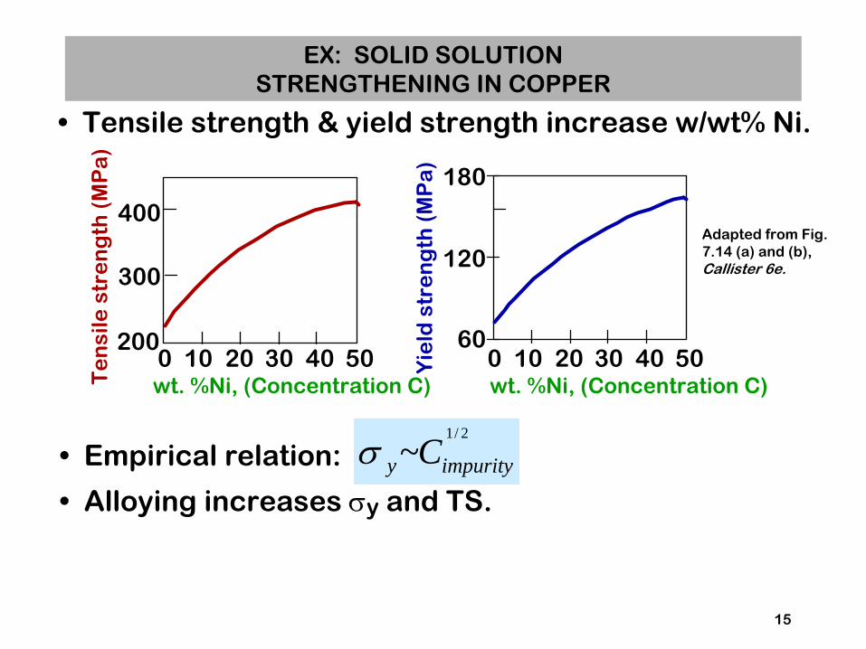
Tensile strength & yield strength increase w/wt% Ni.
•
Empirical relation:
•
Alloying increases σy
and TS.
2/1
~ impurityy Cσ
Adapted from Fig. 7.14 (a) and (b), Callister 6e.
Yie
ld s
tre
ng
th (
MP
a)
wt. %Ni, (Concentration C)
60
120
180
0 10 20 30 40 50
Te
nsi
le s
tre
ng
th (
MP
a)
wt. %Ni, (Concentration C)
200
300
400
0 10 20 30 40 50
EX: SOLID SOLUTION
STRENGTHENING IN COPPER

16
•
Room temperature deformation. –
increase # of dislocations•
Common forming operations change the cross sectional area:
%CW =
Ao −AdAo
x100
Ao Ad
force
dieblank
force
-Forging -Rolling
-Extrusion-Drawing
Adapted from Fig. 11.7, Callister 6e.
tensile force
AoAddie
die
ram billet
container
containerforce
die holder
die
Ao
Adextrusion
roll
AoAd
roll
STRENGTHENING STRATEGY 3: COLD WORK (%CW)

17
•
Ti alloy after cold working:
•
Dislocations entanglewith one anotherduring cold work.
•
Dislocation motionbecomes more difficult.
0.9 μm
Adapted from Fig. 4.6, Callister 6e.(Fig. 4.6 is courtesy of M.R. Plichta, Michigan Technological University.)
DISLOCATIONS DURING COLD WORK

18
•
Dislocation density (ρd) goes up:Carefully prepared sample: ρd
~ 103
mm/mm3
Heavily deformed sample: ρd
~ 1010
mm/mm3
•
Measuring dislocation density:
d= N
A
Area, A
N dislocation pits (revealed by etching)
dislocation pit
ρ
•
Yield stress increasesas ρd
increases:large hardening
small hardening
σ
ε
σy0 σy1
40μm
RESULT OF COLD WORK

Str
ess
% cold work Strain
•
Yield strength (σ
) increases.
•
Tensile strength (TS) increases.
•
Ductility (%EL
or %AR) decreases.
21
y
Adapted from Fig. 7.18, Callister 6e. (Fig. 7.18 is from Metals Handbook: Properties and Selection: Iron and Steels, Vol. 1, 9th ed., B. Bardes (Ed.), American Society for Metals, 1978, p. 221.)
IMPACT OF COLD WORK

22
Cold work ----->
Do=15.2mm Dd=12.2mm
Copper
%CW =
πro2 − πrd
2
πro2
x100 = 35.6%
COLD WORK ANALYSIS
Ductility decreased,Tensile strength increased
•
What is the tensile strength &ductility after cold working?

Effect of Temperature on Strength

•
Results forpolycrystalline iron:
23
•
σy
and TS decrease with increasing test temperature.• %EL increases with increasing test temperature.•
Why? Vacancieshelp dislocationspast obstacles.
1. disl. trapped by obstacle
2. vacancies replace atoms on the disl. half plane
3. disl. glides past obstacle
obstacle
σ-ε
BEHAVIOR VS TEMPERTURE
00 0.1 0.2 0.3 0.4 0.5
200
400
600
800
Str
ess
(M
Pa
)
Strain
-200°C
-100°C
25°C

•
1 hour treatment at Tanneal...decreases TS and increases %EL.
•
Effects of cold work are reversed!
24
•
3 Annealingstages todiscuss...
RecoveryRecrystallizationGrain growth
Adapted from Fig. 7.20, Callister 6e. (Fig.7.20 is adapted from G. Sachs and K.R. van Horn, Practical Metallurgy, Applied Metallurgy, and the Industrial Processing of Ferrous and Nonferrous Metals and Alloys, American Society for Metals, 1940, p. 139.)
Heat treatment: EFFECT OF HEATING AFTER %CWte
nsi
le s
tre
ng
th (
MP
a)
du
cti
lity
(%E
L)
Annealing Temperature (°C)
300
400
500
600 60
50
40
30
20Recovery
Recrystallization
Grain Growth
ductility
tensile strength300 700500100

Annihilation reduces dislocation density.
25
• diffusion
atoms diffuse to regions of tension
extra half-plane of atoms
extra half-plane of atoms
Disl. annhilate and form a perfect atomic plane.
RECOVERY
Dislocation motion without externally applied stress
Reduction of dislocation density reduces strength

•
New crystals are formed that:--have a small disl. density--are small--consume cold-worked crystals.
26
33% coldworkedbrass
New crystalsnucleate after3 sec. at 580C.
Adapted from Fig. 7.19 (a),(b), Callister 6e.
(Fig. 7.19 (a),(b) are courtesy of J.E. Burke, General Electric Company.)
0.6 mm 0.6 mm
RECRYSTALLIZATION
The higher the internal strain, the faster recrystallization will occur

•
All cold-worked crystals are consumed.
27
After 4seconds
After 8seconds
Adapted from Fig. 7.19 (c),(d), Callister 6e.
(Fig. 7.19 (c),(d) are courtesy of J.E. Burke, General Electric Company.)
0.6 mm0.6 mm
FURTHER RECRYSTALLIZATION

•
At longer times, larger grains consume smaller ones. • Why?
28
After 8 s,580C
After 15 min,580C
0.6 mm 0.6 mm
Adapted from Fig. 7.19 (d),(e), Callister 6e.
(Fig. 7.19 (d),(e) are courtesy of J.E. Burke, General Electric Company.)
GRAIN GROWTH
Grain boundary area (and therefore internal energy)is reduced.

28
Heat Treatment of cold worked metal
One hour of baking at each temperature
Grain growth and recovery have a moderate effect on properties compared to recrystallization where disclocation density is more severely affected

Deformation and strengthening of polymers

29
0
unload/reload
0
brittle failure
plastic failure
20
40
60
2 4 6
σ(MPa)
ε
x
x
semi- crystalline
case
amorphous regions
elongate
crystalline regions align
crystalline regions
slide
8
onset of necking
aligned, cross- linked case
networked case
Initial
Near Failure
near failure
Stress-strain curves adapted from Fig. 15.1, Callister 6e. Inset figures along plastic response curve (purple) adapted from Fig. 15.12, Callister 6e. (Fig. 15.12 is from J.M. Schultz, Polymer Materials Science, Prentice-Hall, Inc., 1974, pp. 500-501.)
TENSILE RESPONSE: BRITTLE & PLASTIC

30
•
Drawing...--stretches the polymer prior to use--aligns chains to the stretching direction
•
Results of drawing:--increases the elastic modulus (E) in the
stretching dir.--increases the tensile strength (TS) in the
stretching dir.--decreases ductility (%EL)
•
Annealing
after drawing...
--decreases alignment--reverses effects of drawing.
•
Compare to cold working
in metals!
Adapted from Fig. 15.12, Callister 6e. (Fig. 15.12 is from J.M. Schultz, Polymer Materials Science, Prentice-
Hall, Inc., 1974, pp. 500-501.)
PREDEFORMATION BY DRAWING

32
•
Compare to responses of other polymers:--brittle response
(aligned, cross linked & networked case)
--plastic response
(semi-crystalline case)
Stress-strain curves adapted from Fig. 15.1, Callister 6e.
Inset figures along elastomer curve (green) adapted from Fig. 15.14, Callister 6e. (Fig. 15.14 is from Z.D. Jastrzebski, The Nature and Properties of Engineering Materials, 3rd ed., John Wiley and Sons, 1987.)
TENSILE RESPONSE: ELASTOMER CASE
initial: amorphous chains are kinked, heavily cross-linked.
final: chains are straight,
still cross-linked
0
20
40
60
0 2 4 6
σ(MPa)
ε 8
x
x
x
elastomer
plastic failure
brittle failure
Deformation is reversible!