chapter 8 input/output - acsa labacsa.ustc.edu.cn/ics/downloads/ics18-ch 8.pdf · 2019-10-09 ·...
TRANSCRIPT
2016/11/3 1
Chapter 8 Input/Output
2016 Fall
School of Computer Science and Technology
Lecture on
Introduction to Computing Systems
2016/11/3 2
Review
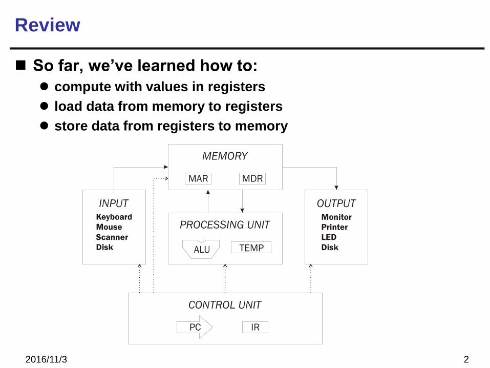
So far, we’ve learned how to:
compute with values in registers
load data from memory to registers
store data from registers to memory
MEMORY
CONTROL UNIT
MAR MDR
IR
PROCESSING UNIT
ALU TEMP
PC
OUTPUT
Monitor
Printer
LED
Disk
INPUTKeyboard
Mouse
Scanner
Disk
SR23
SR2MUX
16
16
16
16[10:0] 16 16
SEXT
SEXT
SEXT
[8:0]
[5:0]
[4:0]SEXT
INPUT
MEM.EN,R,W
16
MAR
16
LD.MAR
PC
GatePC
3
OUTPUTMEMORY
MUX MUX
MDR
…
+
16
16 16
16
ADDR1MUX
2PCMUX
+1
16
MARMUX
SEXT[7:0]
GateMARMUX
LD.PC
16
1616
ADDR2MUX
16
LD.MDR
MUXMIO.EN
GateMDR
16
16
16
ALUA BALUK
2
FINITE STATE
MACHINE
N Z P
RUN
LD.IR IR
16
DR
LD.REG
REG
FILE
SR1
OUT
SR2
OUT 3
3
16
16
GateALU
SR1
LOGIC
16
LD.CC
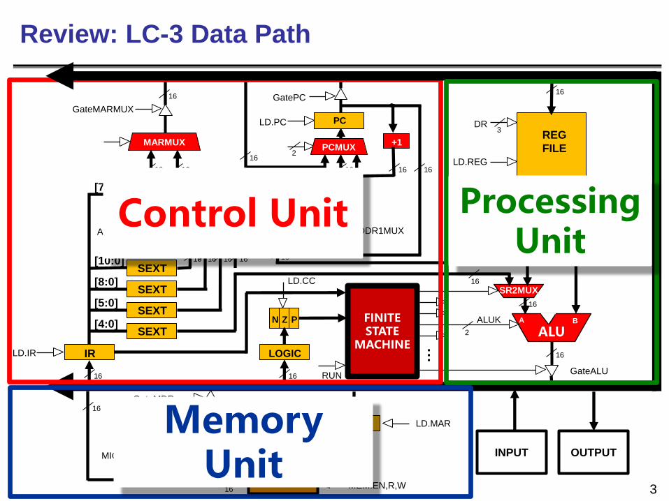
Review: LC-3 Data Path
Control Unit
Memory Unit
Processing Unit
Need for I/O
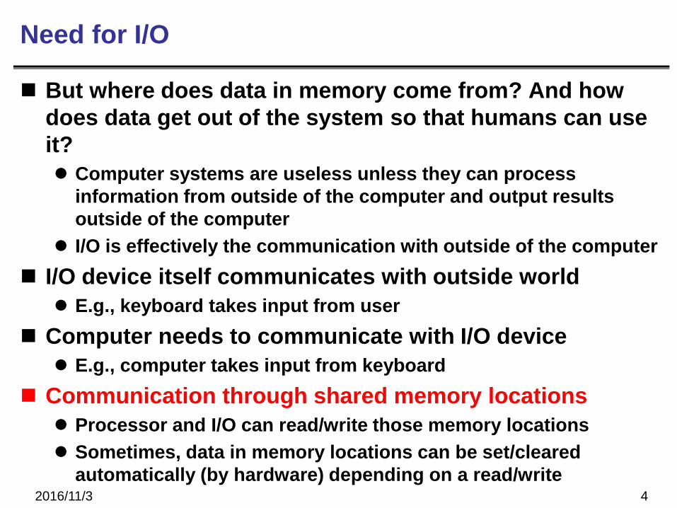
But where does data in memory come from? And how
does data get out of the system so that humans can use
it?
Computer systems are useless unless they can process
information from outside of the computer and output results
outside of the computer
I/O is effectively the communication with outside of the computer
I/O device itself communicates with outside world
E.g., keyboard takes input from user
Computer needs to communicate with I/O device
E.g., computer takes input from keyboard
Communication through shared memory locations
Processor and I/O can read/write those memory locations
Sometimes, data in memory locations can be set/cleared
automatically (by hardware) depending on a read/write 2016/11/3 4
2016/11/3 5
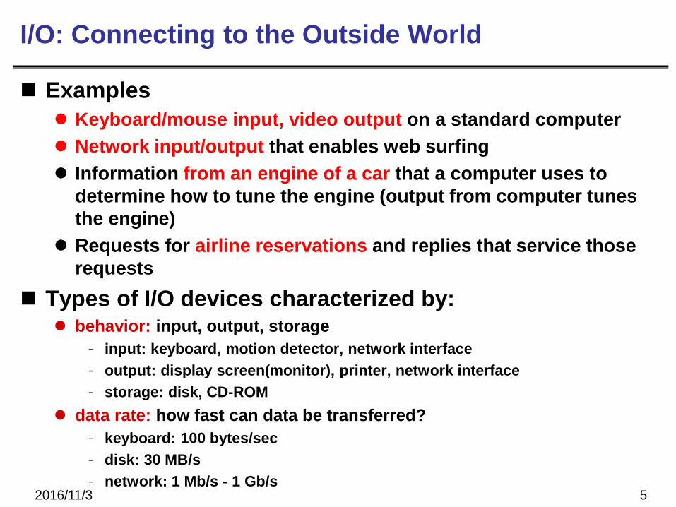
I/O: Connecting to the Outside World
Examples
Keyboard/mouse input, video output on a standard computer
Network input/output that enables web surfing
Information from an engine of a car that a computer uses to
determine how to tune the engine (output from computer tunes
the engine)
Requests for airline reservations and replies that service those
requests
Types of I/O devices characterized by: behavior: input, output, storage
- input: keyboard, motion detector, network interface
- output: display screen(monitor), printer, network interface
- storage: disk, CD-ROM
data rate: how fast can data be transferred?
- keyboard: 100 bytes/sec
- disk: 30 MB/s
- network: 1 Mb/s - 1 Gb/s
2016/11/3 6
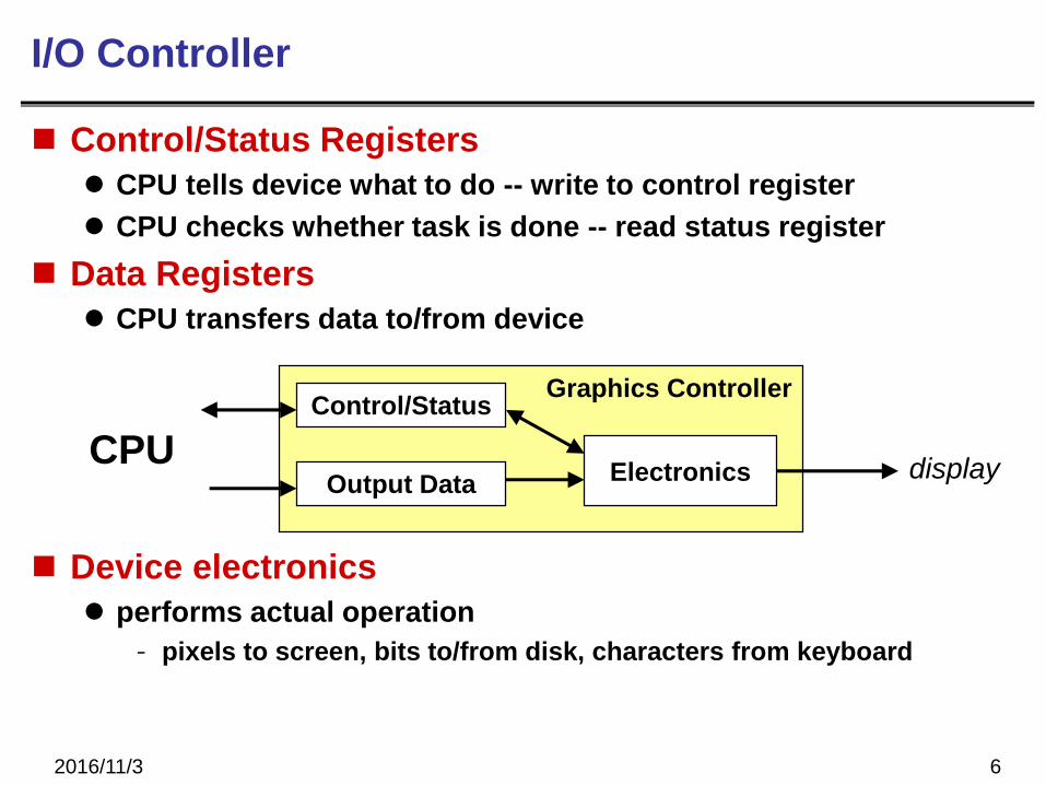
I/O Controller
Control/Status Registers
CPU tells device what to do -- write to control register
CPU checks whether task is done -- read status register
Data Registers
CPU transfers data to/from device
Device electronics
performs actual operation
- pixels to screen, bits to/from disk, characters from keyboard
Graphics ControllerControl/Status
Output Data ElectronicsCPU
display
2016/11/3 7
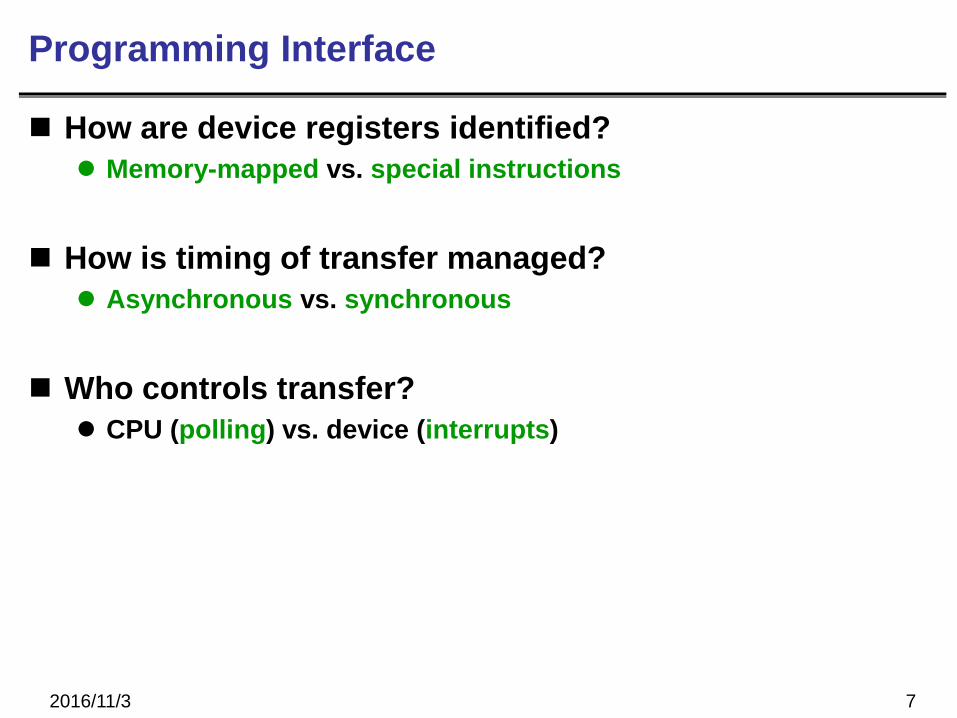
Programming Interface
How are device registers identified?
Memory-mapped vs. special instructions
How is timing of transfer managed?
Asynchronous vs. synchronous
Who controls transfer?
CPU (polling) vs. device (interrupts)
2016/11/3 8
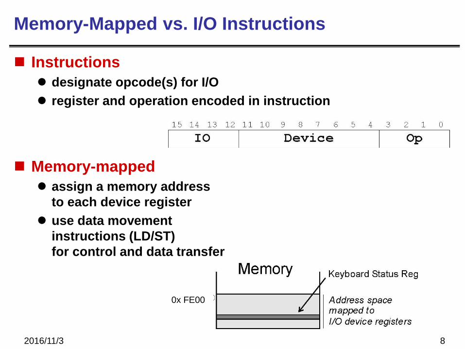
Memory-Mapped vs. I/O Instructions
Instructions
designate opcode(s) for I/O
register and operation encoded in instruction
Memory-mapped
assign a memory address
to each device register
use data movement
instructions (LD/ST)
for control and data transfer
0x FE00
2016/11/3 9
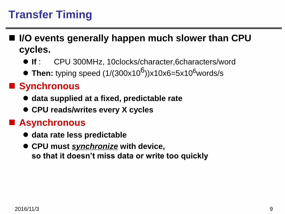
Transfer Timing
I/O events generally happen much slower than CPU
cycles.
If : CPU 300MHz, 10clocks/character,6characters/word
Then: typing speed (1/(300x106))x10x6=5x106words/s
Synchronous
data supplied at a fixed, predictable rate
CPU reads/writes every X cycles
Asynchronous
data rate less predictable
CPU must synchronize with device,
so that it doesn’t miss data or write too quickly
2016/11/3 10
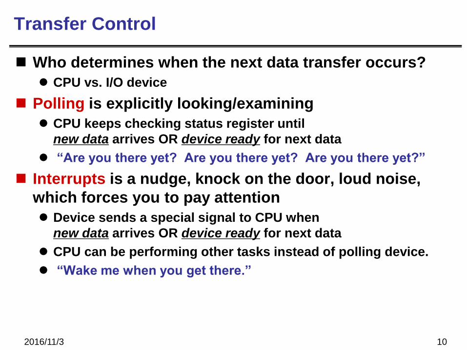
Transfer Control
Who determines when the next data transfer occurs?
CPU vs. I/O device
Polling is explicitly looking/examining
CPU keeps checking status register until
new data arrives OR device ready for next data
“Are you there yet? Are you there yet? Are you there yet?”
Interrupts is a nudge, knock on the door, loud noise,
which forces you to pay attention
Device sends a special signal to CPU when
new data arrives OR device ready for next data
CPU can be performing other tasks instead of polling device.
“Wake me when you get there.”
2016/11/3 11
LC-3
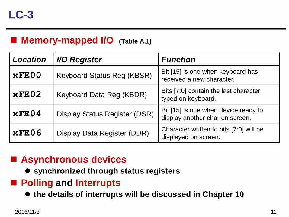
Memory-mapped I/O (Table A.1)
Asynchronous devices synchronized through status registers
Polling and Interrupts the details of interrupts will be discussed in Chapter 10
Location I/O Register Function
xFE00 Keyboard Status Reg (KBSR)Bit [15] is one when keyboard has
received a new character.
xFE02 Keyboard Data Reg (KBDR)Bits [7:0] contain the last character
typed on keyboard.
xFE04 Display Status Register (DSR)Bit [15] is one when device ready to
display another char on screen.
xFE06 Display Data Register (DDR)Character written to bits [7:0] will be
displayed on screen.
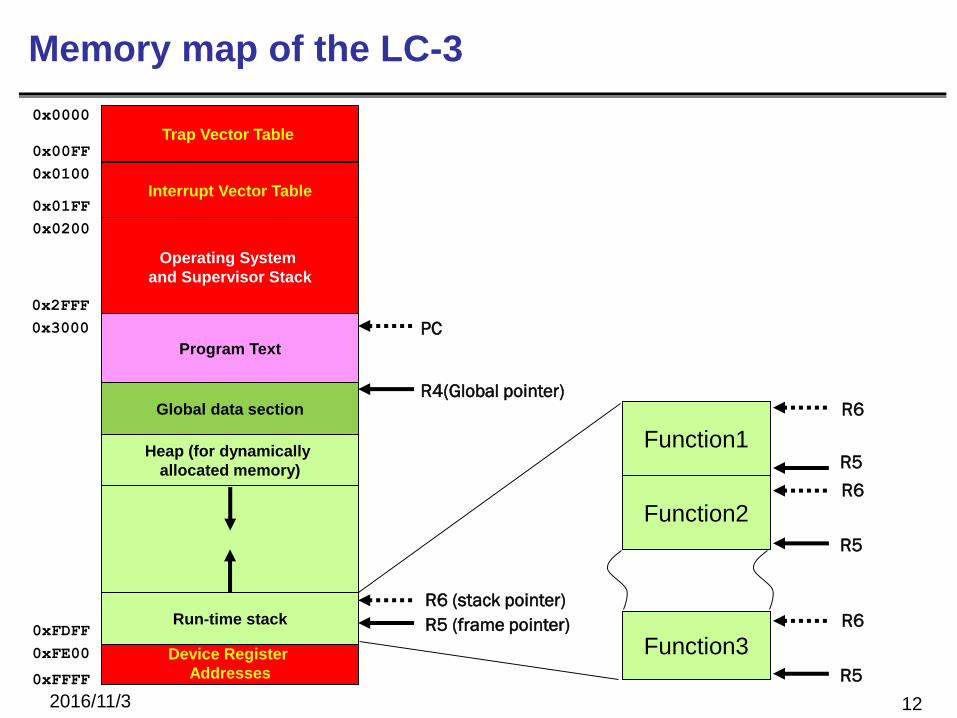
Memory map of the LC-3
2016/11/3 12
PC
R4(Global pointer)
R6 (stack pointer)
Device Register
Addresses
0x0000
0xFFFF
Trap Vector Table
Interrupt Vector Table
Operating System
and Supervisor Stack
0x00FF
0x0100
0x01FF
0x0200
0x2FFF
0x3000
0xFDFF
0xFE00
Run-time stack
Program Text
Global data section
Heap (for dynamically
allocated memory)
R5 (frame pointer)
R5
Function2R6
R5
R6
Function3
Function1
R5
R6
2016/11/3 13
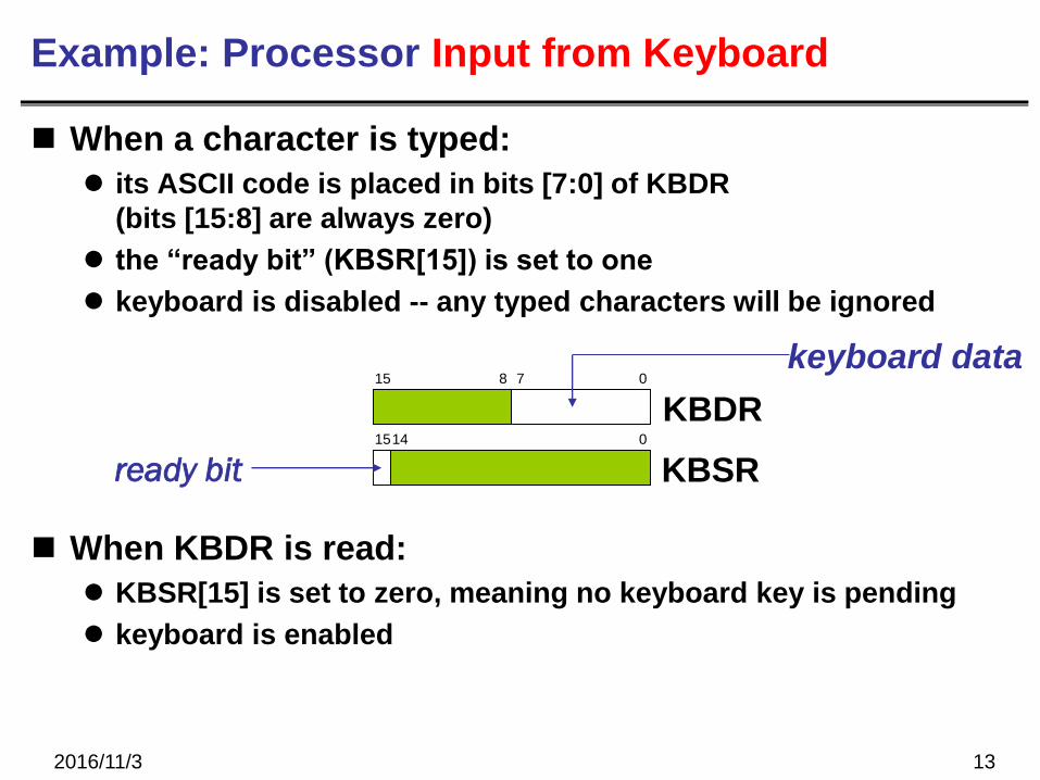
Example: Processor Input from Keyboard
When a character is typed:
its ASCII code is placed in bits [7:0] of KBDR
(bits [15:8] are always zero)
the “ready bit” (KBSR[15]) is set to one
keyboard is disabled -- any typed characters will be ignored
When KBDR is read:
KBSR[15] is set to zero, meaning no keyboard key is pending
keyboard is enabled
KBSR
KBDR15 8 7 0
1514 0
keyboard data
ready bit
2016/11/3 14
Memory-mapped Operations
How do we read ready bit?
How do we test whether the bit is one?
How do we read keyboard data?
2016/11/3 15
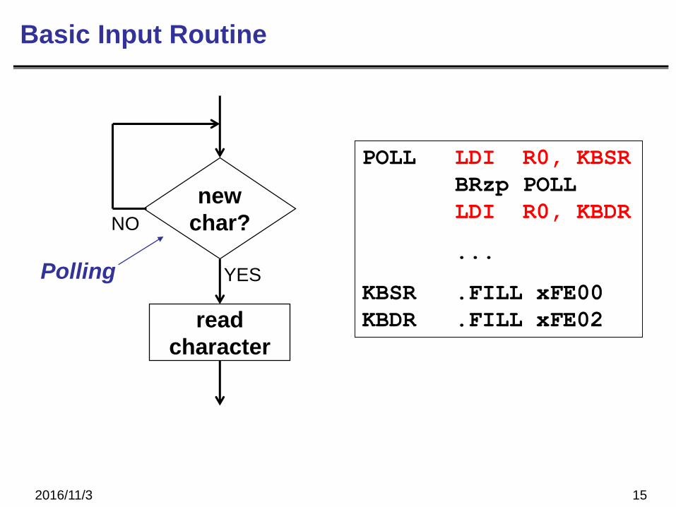
Basic Input Routine
new
char?
read
character
YES
NO
Polling
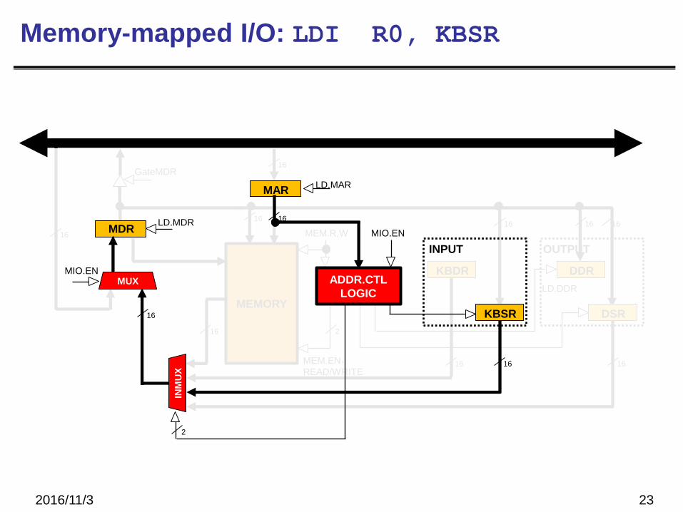
POLL LDI R0, KBSR
BRzp POLL
LDI R0, KBDR
...
KBSR .FILL xFE00
KBDR .FILL xFE02
Memory-mapped I/O
2016/11/3 16
MEM.EN,READ/WRITE
16
ADDR.CTL
LOGICMEMORY
MDR LD.MDR
MUXMIO.EN
GateMDR
16
MAR
16
LD.MAR
KBDR
KBSR
DDR
DSR
INM
UX
16 1616
16 16 1616
MEM.R,W
INPUT OUTPUT
MIO.EN
2
16 2
LD.DDR
16

SR1
16
SR23
SR2MUX
16
16
16
16[10:0] 16 16
SEXT
SEXT
SEXT
[8:0]
[5:0]
[4:0]SEXT
INPUT
MEM.EN,R,W
16
GatePC
17
OUTPUTMEMORY
MUX MUX
MDR
…
+
16
16 16
16
ADDR1MUX
2PCMUX
+1
16
MARMUX
SEXT[7:0]
GateMARMUX
LD.PC
16
1616
ADDR2MUX
16
LD.MDR
MUXMIO.EN
GateMDR
16
16
16
ALUA BALUK
2
FINITE STATE
MACHINE
N Z P
RUN
LD.IR IR
16
DR
LD.REG
REG
FILE
SR1
OUT
SR2
OUT 3
3
16
GateALU
LOGIC
16
LD.CC
PC
MAR
16
LD.MAR
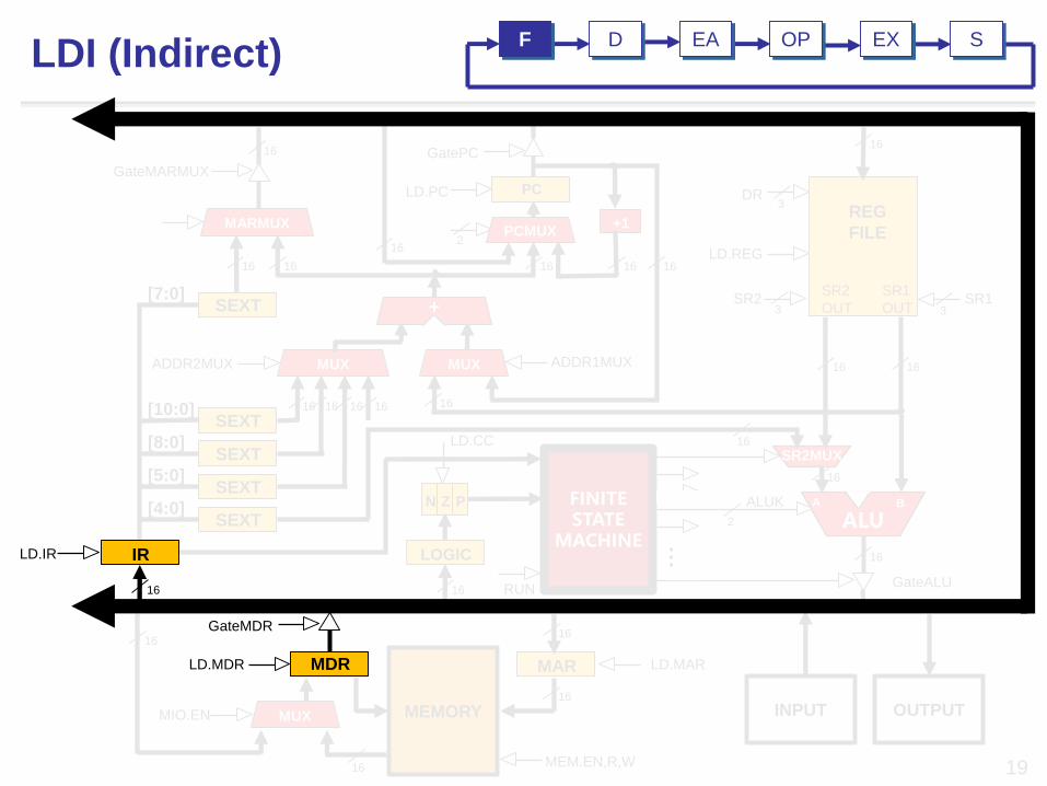
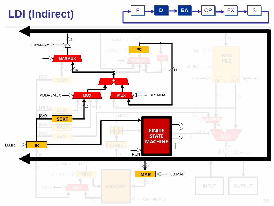
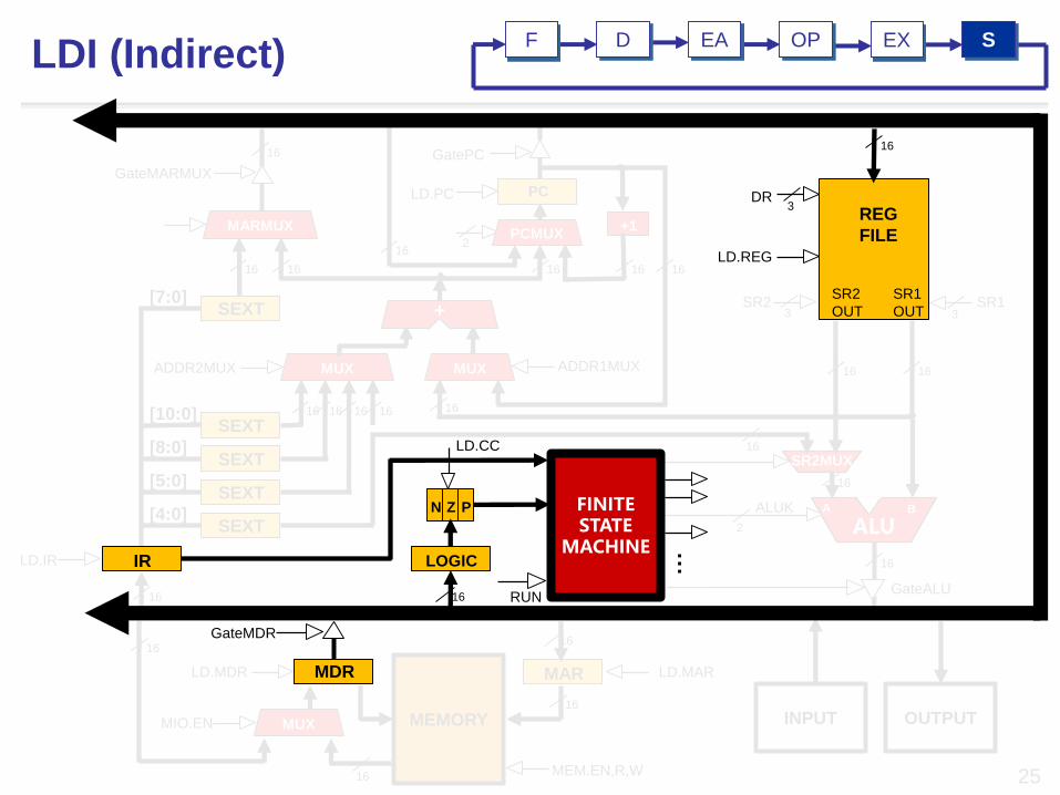
LDI (Indirect)EA OP EX SF D

16
16
GatePC
SR23
SR2MUX
16
16
16
16[10:0] 16 16
SEXT
SEXT
SEXT
[8:0]
[5:0]
[4:0]SEXT
INPUT
LD.MAR
18
OUTPUT
MUX MUX…
+
16
16 16
16
ADDR1MUX
MARMUX
SEXT[7:0]
GateMARMUX
16
1616
ADDR2MUX
GateMDR
16
16
ALUA BALUK
2
FINITE STATE
MACHINE
N Z P
RUN
LD.IR IR
16
DR
LD.REG
REG
FILE
SR1
OUT
SR2
OUT 3
3
16
16
GateALU
SR1
LOGIC
16
LD.CC
16
PC
2PCMUX
+1
LD.PC
MEM.EN,R,W
16
MAR
MEMORY
MDRLD.MDR
MUX
16
MIO.EN
LDI (Indirect)EA OP EX SF D
RUN
LD.CC
MEM.EN,R,W
16
MAR
16
LD.MAR
PC
GatePC
19
ALUA B
SR2MUX
INPUT OUTPUTMEMORY
FINITE STATE
MACHINE
MUX MUX
N Z P
LOGIC
1616…
+
16
16
16 16
DR
LD.REG
SR2 SR1
ALUK
REG
FILE
SR1
OUT
SR2
OUT
16
16
GateALU
16
16
ADDR1MUX
2
3 3
3
PCMUX+1
16
MARMUX
SEXT
SEXT
SEXT
SEXT
SEXT
[10:0]
[8:0]
[5:0]
[4:0]
[7:0]
16 16
GateMARMUX
LD.PC
16
1616
ADDR2MUX
16
MUXMIO.EN
1616
16
16
2
LD.IR IR
16
MDRLD.MDR
GateMDR
LDI (Indirect)EA OP EX SF D
16
16
MEMORY
16
N Z P
LOGIC
LD.CC
PCMUX+1
1616
GatePC
2
LD.PC
16
16[10:0] 16 16 16
SEXT
SEXT
SEXT[5:0]
[4:0]
SEXT[7:0]
16
INPUT
MEM.EN,R,W
16
20
OUTPUT
MDR
16
LD.MDR
MUXMIO.EN
GateMDR16
16
ALU2
16
GateALU
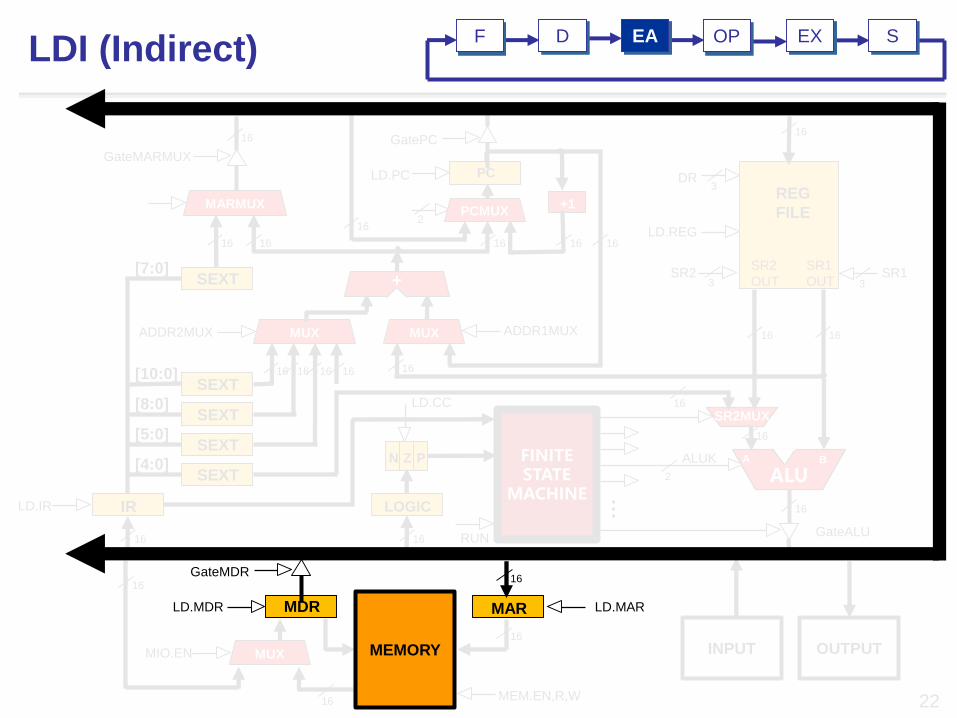
LDI (Indirect)
SR23
16
A BALUK
16
DR
LD.REG
REG
FILE
SR1
OUT
SR2
OUT 3
3
SR1
SR2MUX
16
LD.IR
SEXT
PC
MUX MUX…
+
16
ADDR1MUX
MARMUX
GateMARMUX
16
ADDR2MUX
16
FINITE STATE
MACHINEIR
16
EADF OP EX S
MAR
16
RUN
[8:0]
LD.MAR

16
SR23+
16
MARMUX
SEXT[7:0]
GateMARMUX
16
1616
DR
LD.REG
3
16
PC
2PCMUX
+1
LD.PC
16
GatePC
SR2MUX
16
16
16
16[10:0] 16 16
SEXT
SEXT
SEXT
[8:0]
[5:0]
[4:0]SEXT
INPUT
LD.MAR
21
OUTPUT
MUX MUX…
16 16
16
ADDR1MUXADDR2MUX
GateMDR
16
16
ALUA BALUK
2
FINITE STATE
MACHINE
N Z P
RUN
LD.IR IR
16
REG
FILE
SR1
OUT
SR2
OUT 3
16
16
GateALU
SR1
LOGIC
16
LD.CC
MEM.EN,R,W
16
MAR
MEMORY
MDRLD.MDR
MUX
16
MIO.EN
LDI (Indirect)OP EX SDF EA
16
MEM.EN,R,W16
MUXMIO.EN
16
SR23+
16
MARMUX
SEXT[7:0]
GateMARMUX
16
1616
DR
LD.REG
3
16
PC
2PCMUX
+1
LD.PC
GatePC
SR2MUX
16
16
16
16[10:0] 16 16
SEXT
SEXT
SEXT
[8:0]
[5:0]
[4:0]SEXT
INPUT
22
OUTPUT
MUX MUX…
16 16
16
ADDR1MUXADDR2MUX
16
16
ALUA BALUK
2
FINITE STATE
MACHINE
N Z P
RUN
LD.IR IR
16
REG
FILE
SR1
OUT
SR2
OUT 3
16
16
GateALU
SR1
LOGIC
16
LD.CC
MAR
MEMORY
MDRLD.MDR
LDI (Indirect)EA EX SDF OP
GateMDR16
LD.MAR
16
23
KBDR
16
GateMDR
2
16
Memory-mapped I/O: LDI R0, KBSR
2016/11/3
MEM.EN,READ/WRITE
MEMORY
16
DDR
DSR
16
16 16 16
MEM.R,W
OUTPUT
16
LD.DDR
16
MARLD.MAR
ADDR.CTL
LOGIC
MDR
MUXMIO.EN
INM
UX
16
2
LD.MDR
KBSR
16
INPUT
MIO.EN

KBSR
16
16
24
GateMDR
2
16
Memory-mapped I/O: LDI R0, KBDR
2016/11/3
MEM.EN,READ/WRITE
MEMORY
16
DDR
DSR
16
16 16 16
MEM.R,W
OUTPUT
16
LD.DDR
16
MARLD.MAR
ADDR.CTL
LOGIC
MDR
MUXMIO.EN
INM
UX
16
2
LD.MDR
INPUT
MIO.EN
KBDR
16
LD.IR
MEM.EN,R,W
16
MAR
16
LD.MAR
MEMORY
3SR1SR2
3
SR2MUX
16
16
16
16[10:0] 16 16
SEXT
SEXT
SEXT
[8:0]
[5:0]
[4:0]SEXT
INPUT
PC
GatePC
25
OUTPUT
MUX MUX
+
16
16 16
16
ADDR1MUX
2PCMUX
+1
16
MARMUX
SEXT[7:0]
GateMARMUX
LD.PC
16
1616
ADDR2MUX
16
LD.MDR
MUXMIO.EN
16
16
16
ALUA BALUK
2
16
16
GateALU
DR
LD.REG
REG
FILE
SR1
OUT
SR2
OUT
3
16
…
FINITE STATE
MACHINE
N Z P
RUN
LOGIC
16
LD.CC
IR
MDR
GateMDR
LDI (Indirect)EA OP SDF EX
2016/11/3 26
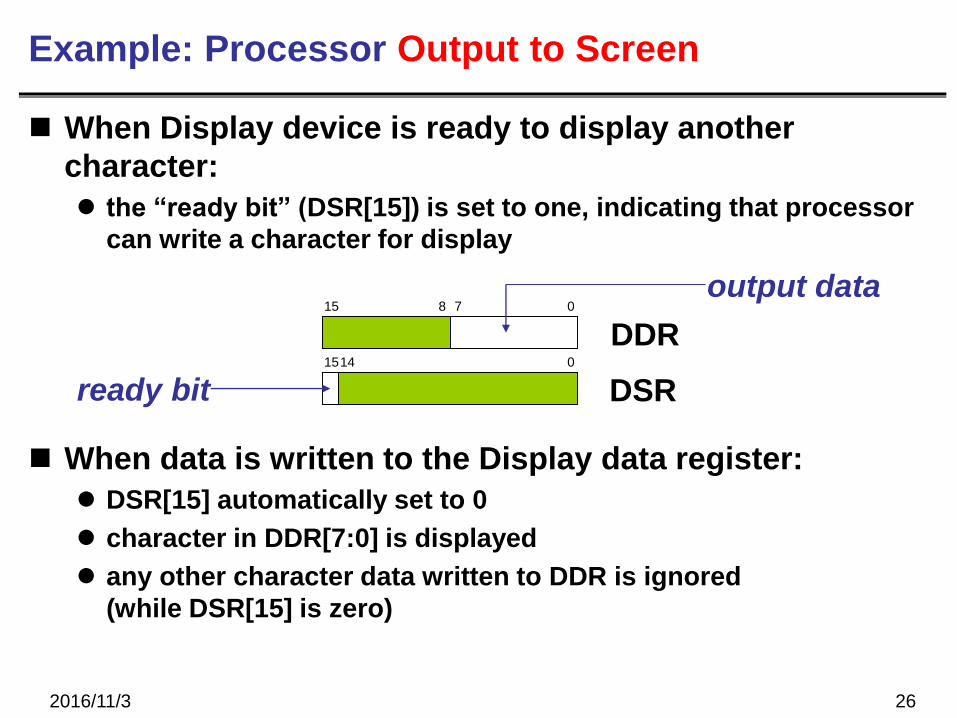
Example: Processor Output to Screen
When Display device is ready to display another
character:
the “ready bit” (DSR[15]) is set to one, indicating that processor
can write a character for display
When data is written to the Display data register:
DSR[15] automatically set to 0
character in DDR[7:0] is displayed
any other character data written to DDR is ignored
(while DSR[15] is zero)
DSR
DDR15 8 7 0
1514 0
output data
ready bit
2016/11/3 27
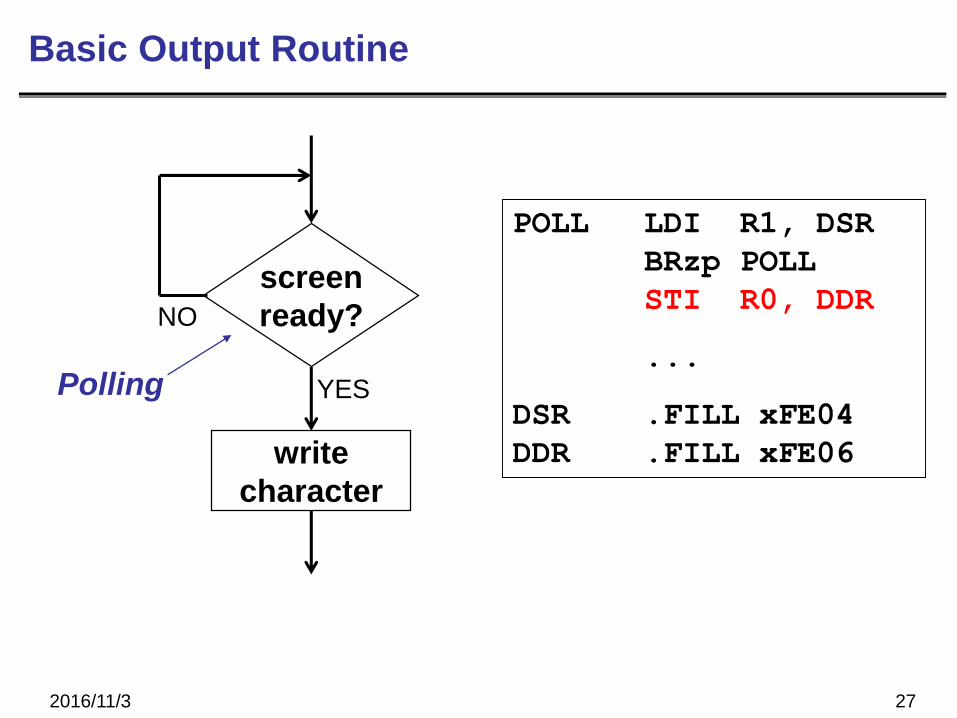
Basic Output Routine
screen
ready?
write
character
YES
NO
Polling
POLL LDI R1, DSR
BRzp POLL
STI R0, DDR
...
DSR .FILL xFE04
DDR .FILL xFE06
SR1
16
SR23
SR2MUX
16
16
16
16[10:0] 16 16
SEXT
SEXT
SEXT
[8:0]
[5:0]
[4:0]SEXT
INPUT
MEM.EN,R,W
16
GatePC
28
OUTPUTMEMORY
MUX MUX
MDR
…
+
16
16 16
16
ADDR1MUX
2PCMUX
+1
16
MARMUX
SEXT[7:0]
GateMARMUX
LD.PC
16
1616
ADDR2MUX
16
LD.MDR
MUXMIO.EN
GateMDR
16
16
16
ALUA BALUK
2
FINITE STATE
MACHINE
N Z P
RUN
LD.IR IR
16
DR
LD.REG
REG
FILE
SR1
OUT
SR2
OUT 3
3
16
GateALU
LOGIC
16
LD.CC
PC
MAR
16
LD.MAR
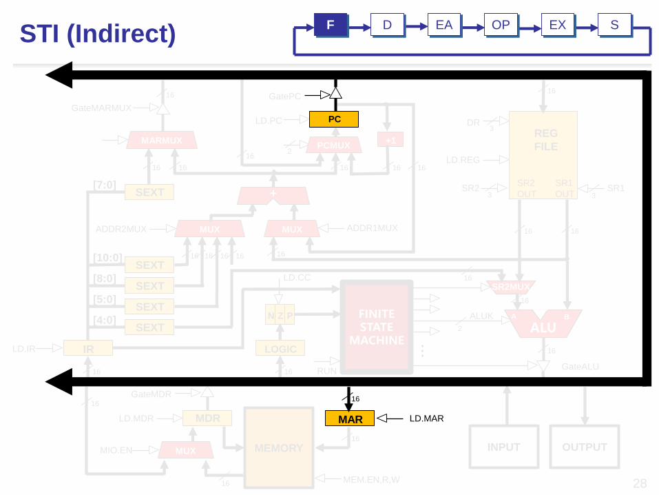
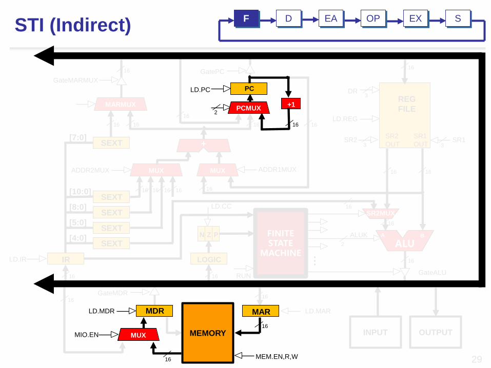
STI (Indirect)EA OP EX SF D
16
16
GatePC
SR23
SR2MUX
16
16
16
16[10:0] 16 16
SEXT
SEXT
SEXT
[8:0]
[5:0]
[4:0]SEXT
INPUT
LD.MAR
29
OUTPUT
MUX MUX…
+
16
16 16
16
ADDR1MUX
MARMUX
SEXT[7:0]
GateMARMUX
16
1616
ADDR2MUX
GateMDR
16
16
ALUA BALUK
2
FINITE STATE
MACHINE
N Z P
RUN
LD.IR IR
16
DR
LD.REG
REG
FILE
SR1
OUT
SR2
OUT 3
3
16
16
GateALU
SR1
LOGIC
16
LD.CC
16
PC
2PCMUX
+1
LD.PC
MEM.EN,R,W
16
MAR
MEMORY
MDRLD.MDR
MUX
16
MIO.EN
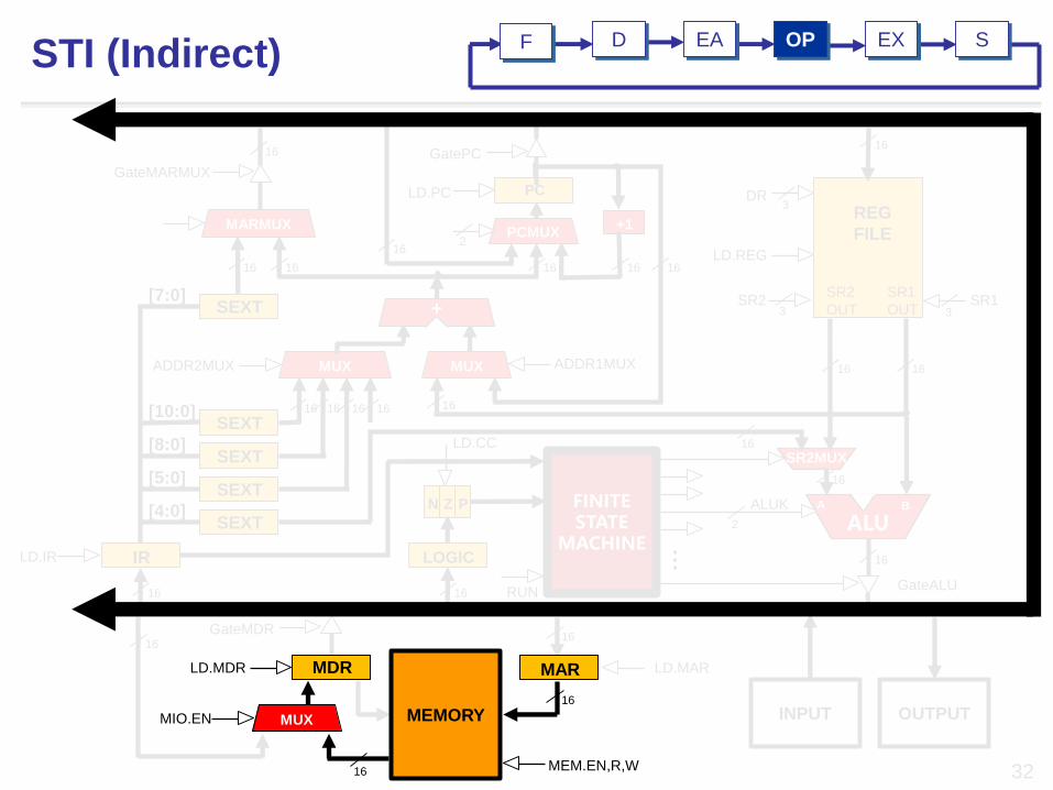
STI (Indirect)EA OP EX SF D

RUN
LD.CC
MEM.EN,R,W
16
MAR
16
LD.MAR
PC
GatePC
30
ALUA B
SR2MUX
INPUT OUTPUTMEMORY
FINITE STATE
MACHINE
MUX MUX
N Z P
LOGIC
1616…
+
16
16
16 16
DR
LD.REG
SR2 SR1
ALUK
REG
FILE
SR1
OUT
SR2
OUT
16
16
GateALU
16
16
ADDR1MUX
2
3 3
3
PCMUX+1
16
MARMUX
SEXT
SEXT
SEXT
SEXT
SEXT
[10:0]
[8:0]
[5:0]
[4:0]
[7:0]
16 16
GateMARMUX
LD.PC
16
1616
ADDR2MUX
16
MUXMIO.EN
1616
16
16
2
LD.IR IR
16
MDRLD.MDR
GateMDR
STI (Indirect)EA OP EX SF D

16
16
MEMORY
16
N Z P
LOGIC
LD.CC
PCMUX+1
1616
GatePC
2
LD.PC
16
16[10:0] 16 16 16
SEXT
SEXT
SEXT[5:0]
[4:0]
SEXT[7:0]
16
INPUT
MEM.EN,R,W
16
31
OUTPUT
MDR
16
LD.MDR
MUXMIO.EN
GateMDR16
16
ALU2
16
GateALU
STI (Indirect)
SR23
16
A BALUK
16
DR
LD.REG
REG
FILE
SR1
OUT
SR2
OUT 3
3
SR1
SR2MUX
16
LD.IR
SEXT
PC
MUX MUX…
+
16
ADDR1MUX
MARMUX
GateMARMUX
16
ADDR2MUX
16
FINITE STATE
MACHINEIR
16
EADF OP EX S
MAR
16
RUN
[8:0]
LD.MAR
PC
2PCMUX
+1
LD.PC
16
16
16
GatePC
SR23
SR2MUX
16
16
16
16[10:0] 16 16
SEXT
SEXT
SEXT
[8:0]
[5:0]
[4:0]SEXT
INPUT
LD.MAR
32
OUTPUT
MUX MUX…
+
16
16 16
16
ADDR1MUX
MARMUX
SEXT[7:0]
GateMARMUX
16
1616
ADDR2MUX
GateMDR
16
16
ALUA BALUK
2
FINITE STATE
MACHINE
N Z P
RUN
LD.IR IR
16
DR
LD.REG
REG
FILE
SR1
OUT
SR2
OUT 3
3
16
16
GateALU
SR1
LOGIC
16
LD.CC
MEM.EN,R,W
16
MAR
MEMORY
MDRLD.MDR
MUX
16
MIO.EN
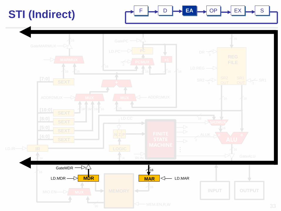
STI (Indirect)EA OP EX SDF
MEMORY16
MEM.EN,R,W16
MUXMIO.EN
16
SR23+
16
MARMUX
SEXT[7:0]
GateMARMUX
16
1616
DR
LD.REG
3
16
PC
2PCMUX
+1
LD.PC
GatePC
SR2MUX
16
16
16
16[10:0] 16 16
SEXT
SEXT
SEXT
[8:0]
[5:0]
[4:0]SEXT
INPUT
33
OUTPUT
MUX MUX…
16 16
16
ADDR1MUXADDR2MUX
16
16
ALUA BALUK
2
FINITE STATE
MACHINE
N Z P
RUN
LD.IR IR
16
REG
FILE
SR1
OUT
SR2
OUT 3
16
16
GateALU
SR1
LOGIC
16
LD.CC
MARMDRLD.MDR
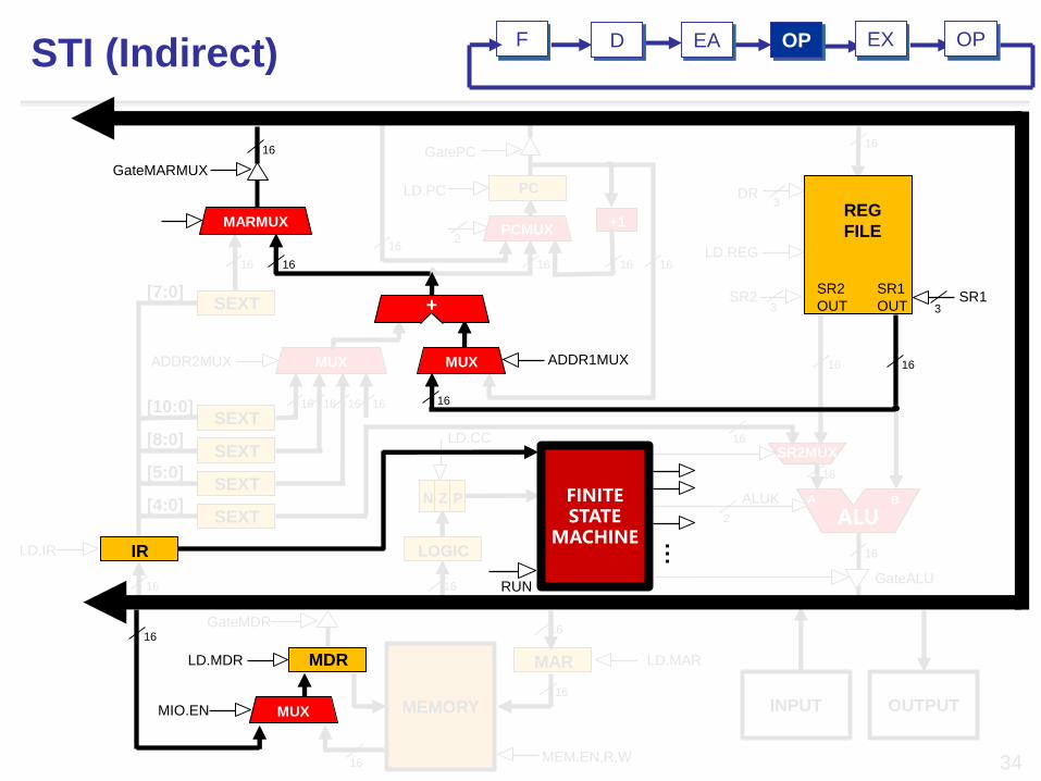
STI (Indirect)EA EX SDF OP
GateMDR16
LD.MAR
16
16
SEXT[10:0] 16 16 16
SEXT[7:0]
[8:0]
16
MUXADDR2MUX
GateMDR
N Z P
LOGIC
16
LD.CC
16
DR3
LD.REG
SR23
16
PC
GatePC
2PCMUX
+1
16
LD.PC
16
16
LD.IR
MEM.EN,R,W
16
MAR
16
LD.MAR
MEMORY
SR2MUX
16
16
SEXT
SEXT[5:0]
[4:0]SEXT
INPUT
34
OUTPUT
16
16
ALUA BALUK
2
16
GateALU
SR1
OUT
…
FINITE STATE
MACHINE
RUN
IR
MDR
STI (Indirect)
MUX
+
16
ADDR1MUX
MARMUX
GateMARMUX
16
16
REG
FILE
SR2
OUT 3SR1
16
LD.MDR
MUXMIO.EN
16
F EA OPD EX OP
16
16
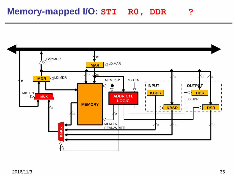
Memory-mapped I/O: STI R0, DDR ?
2016/11/3 35
MEM.EN,READ/WRITE
ADDR.CTL
LOGICMEMORY
MDR LD.MDR
MUXMIO.EN
GateMDR
16
KBDR
KBSR DSR
INM
UX
1616
1616
MEM.R,W
INPUT OUTPUT
MIO.EN
2
16 2
16
MAR
16
LD.MAR
DDR
LD.DDR
1616
2016/11/3 36
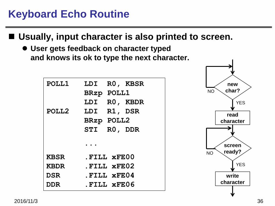
Keyboard Echo Routine
Usually, input character is also printed to screen.
User gets feedback on character typed
and knows its ok to type the next character.
new
char?
read
character
YES
NO
screen
ready?
write
character
YES
NO
POLL1 LDI R0, KBSR
BRzp POLL1
LDI R0, KBDR
POLL2 LDI R1, DSR
BRzp POLL2
STI R0, DDR
...
KBSR .FILL xFE00
KBDR .FILL xFE02
DSR .FILL xFE04
DDR .FILL xFE06
2016/11/3 37
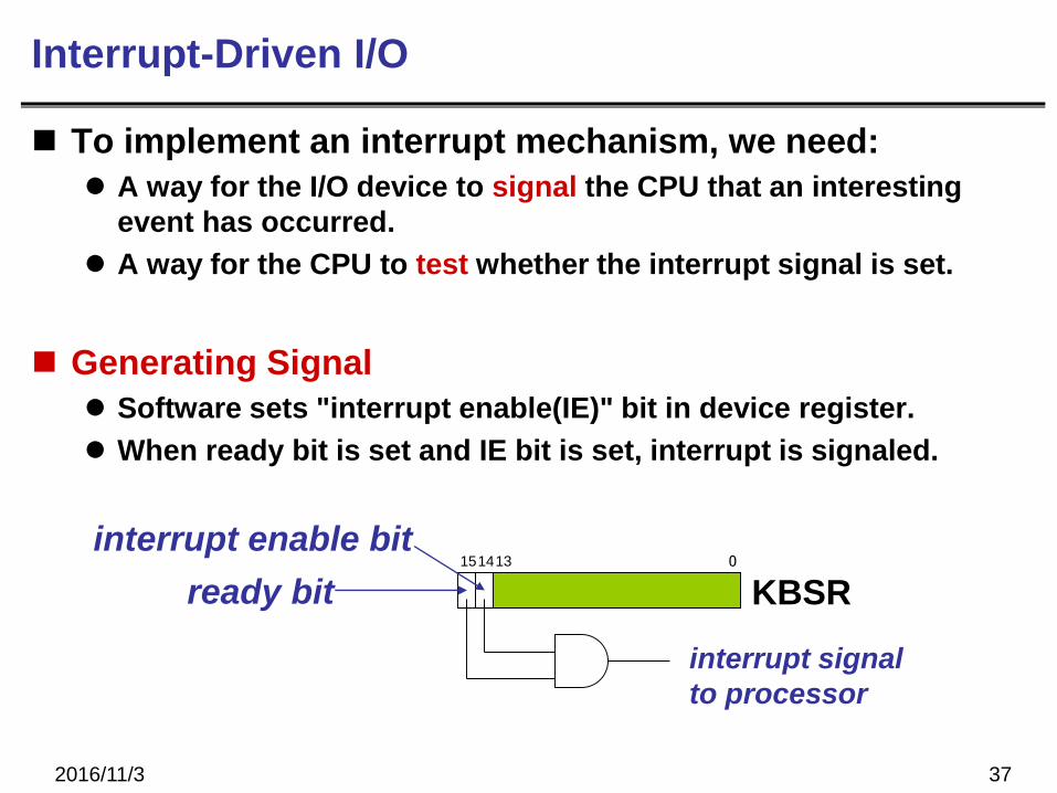
Interrupt-Driven I/O
To implement an interrupt mechanism, we need:
A way for the I/O device to signal the CPU that an interesting
event has occurred.
A way for the CPU to test whether the interrupt signal is set.
Generating Signal
Software sets "interrupt enable(IE)" bit in device register.
When ready bit is set and IE bit is set, interrupt is signaled.
KBSR1514 0
ready bit13
interrupt enable bit
interrupt signal
to processor
2016/11/3 38
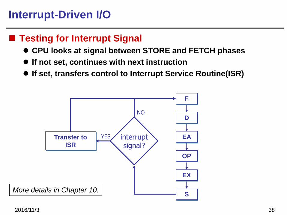
Interrupt-Driven I/O
Testing for Interrupt Signal
CPU looks at signal between STORE and FETCH phases
If not set, continues with next instruction
If set, transfers control to Interrupt Service Routine(ISR)
EA
OP
EX
S
F
D
interruptsignal?
Transfer to
ISR
NO
YES
More details in Chapter 10.
2016/11/3 39
Review Questions
What is the danger of not testing the DSR
before writing data to the Display screen?
What is the danger of not testing the KBSR
before reading data from the keyboard?
What if the Display were a synchronous device,
e.g., we know that it will be ready 1 microsecond after
character is written.
Can we avoid polling? How?
What are advantages and disadvantages?
2016/11/3 40
Review Questions
Do you think polling is a good approach for other
devices, such as a disk or a network interface?
What is advantage of using LDI/STI for accessing
device registers?