chapter 8: inter vlan-routingteguhkurniawan.staff.telkomuniversity.ac.id/files/2016/04/inter... ·...
TRANSCRIPT

CHAPTER 8: INTER VLAN-ROUTING
Routing & Switching

CHAPTER 8
8.1 Inter-VLAN Routing Configuration
8.2 Troubleshooting Inter-VLAN Routing
8.3 Layer 3 Switching
8.4 Summary

CHAPTER 8: OBJECTIVES
• Describe the three primary options for enabling inter-VLAN routing.
• Configure legacy inter-VLAN routing.
• Configure router-on-a-stick inter-VLAN routing.
• Troubleshoot common inter-VLAN configuration issues.
• Troubleshoot common IP addressing issues in an inter-VLAN-routed environment.
• Configure inter-VLAN routing using Layer 3 switching.
• Troubleshoot inter-VLAN routing in a Layer 3-switched environment.

8.1 INTER-VLAN ROUTING CONFIGURATION

INTER-VLAN ROUTING OPERATION
WHAT IS INTER-VLAN ROUTING?
• Layer 2 switches cannot forward traffic between VLANs without the assistance of a router.
• Inter-VLAN routing is a process for forwarding network traffic from one VLAN to another, using a router.

BAGAIMANA INTERLVLANROUTING BEKERJA?
• Device network yang berbeda VLAN tidak dapatberkomunukasi dengan device lainnya tanpa routing danswitch L3, yang berfungsi untuk merutekan trafik antar VLAN.
• Konfigurasi VLAN bermanfaat untuk mengkontrol size broadcast domain dan menjaga trafik local
• Untuk dapat mengkoneksikan end-device didalam satu VLAN dengan VLAN lainnya dibutuhkan komunikasi interVLAN
• InterVLAN membutuhkan interface fisik router atau sub-interface router sebagai gateway masing-masing
• Penggunaan sub-interface router untuk inter-VLAN disebutsebagai router-on-stick
• Sub-interface router untuk interVLAN membutuhkan protocol trunking ISL atau 802.1q

CARA KONFIGURASIINTERVLAN
• Router-on-stick
• L3 Switch dengan SVI
• Per-interface interVLAN routing

KONFIGURASI ROUTER-ON-STICK
• Pilih interface router
• Setting sub-interface
• Setting protocol trunking ISL atau 802.1q

INTER-VLAN ROUTING -SVI

INTER-VLAN ROUTING OPERATION
LEGACY INTER-VLAN ROUTINGIn the past:
• Actual routers were used to route between VLANs.
• Each VLAN was connected to a different physical router interface.
• Packets would arrive on the router through one through interface, be routed and leave through another.
• Because the router interfaces were connected to VLANs and had IP addresses from that specific VLAN, routing between VLANs was achieved.
• Large networks with large number of VLANs required many router interfaces.

INTER-VLAN ROUTING OPERATION
ROUTER-ON-A-STICK INTER-VLAN ROUTING
• The router-on-a-stick approach uses a different path to route between VLANs.
• One of the router’s physical interfaces is configured as a 802.1Q trunk port so it can understand VLAN tags.
• Logical subinterfaces are created; one subinterface per VLAN.
• Each subinterface is configured with an IP address from the VLAN it represents.
• VLAN members (hosts) are configured to use the subinterface address as a default gateway.
• Only one of the router’s physical interface is used.

INTER-VLAN ROUTING OPERATION
MULTILAYER SWITCH INTER-VLAN ROUTING
• Multilayer switches can perform Layer 2 and Layer 3 functions, replacing the need for dedicated routers.
• Multilayer switches support dynamic routing and inter-VLAN routing.
• The multilayer switch must have IP routing enabled.
• A switch virtual interface (SVI) exists for VLAN 1 by default. On a multilayer switch, a logical (layer 3) interface can be configured for any VLAN.
• The switch understands network-layer PDUs; therefore, can route between its SVIs, just as a router routes between its interfaces.
• With a multilayer switch, traffic is routed internal to the switch device.
• This routing process is a suitable and scalable solution.

CONFIGURE LEGACY INTER-VLAN ROUTING
PREPARATION
• Legacy inter-VLAN routing requires routers to have multiple physical interfaces.
• Each one of the router’s physical interfaces is connected to a unique VLAN.
• Each interface is also configured with an IP address for the subnet associated with the particular VLAN.
• Network devices use the router as a gateway to access the devices connected to the other VLANs.

CONFIGURE LEGACY INTER-VLAN ROUTING
PREPARATION (CONT.)
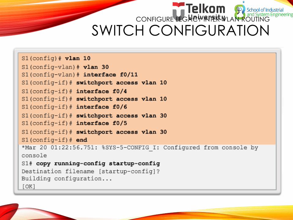
CONFIGURE LEGACY INTER-VLAN ROUTING
SWITCH CONFIGURATION
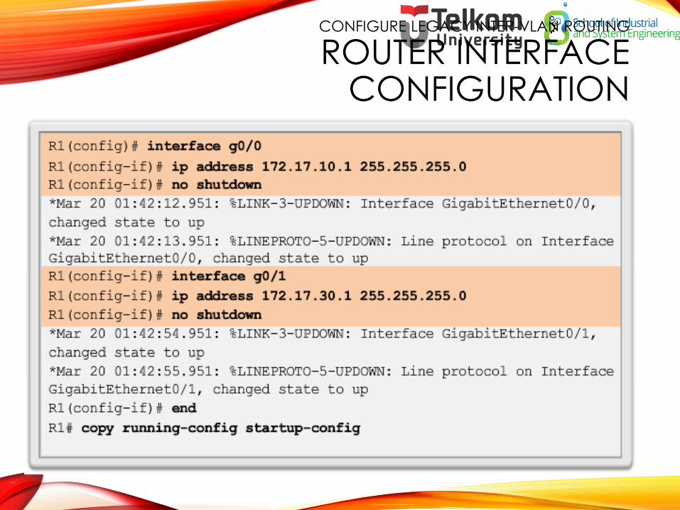
CONFIGURE LEGACY INTER-VLAN ROUTING
ROUTER INTERFACE CONFIGURATION

CONFIGURE ROUTER-ON-A-STICK
PREPARATION
• An alternative to legacy inter-VLAN routing is to use VLAN trunking and subinterfaces.
• VLAN trunking allows a single physical router interface to route traffic for multiple VLANs.
• The physical interface of the router must be connected to a trunk link on the adjacent switch.
• On the router, subinterfaces are created for each unique VLAN.
• Each subinterface is assigned an IP address specific to its subnet or VLAN and is also configured to tag frames for that VLAN.

CONFIGURE ROUTER-ON-A-STICK
SWITCH CONFIGURATION

CONFIGURE ROUTER-ON-A-STICK
ROUTER SUBINTERFACECONFIGURATION

CONFIGURE ROUTER-ON-A-STICK
VERIFYING SUBINTERFACES
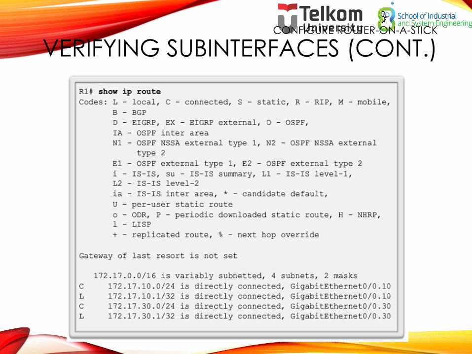
CONFIGURE ROUTER-ON-A-STICK
VERIFYING SUBINTERFACES (CONT.)

• Access to devices on remote VLANs can be tested using the ping command.
• The ping command sends an ICMP echo request to the destination address.
• When a host receives an ICMP echo request, it responds with an ICMP echo reply.
• Tracert is a useful utility for confirming the routed path taken between two devices.
Configure Router-on-a-Stick
Verifying Routing

3.2 TROUBLESHOOT INTER-VLAN ROUTING

• When using the legacy routing model, ensure that the switch ports connect to the router interfaces and are configured with the correct VLANs.
• Use the switchport access vlan [appropriate vlan#] command to correct any erroneous VLAN port assignment.
• Ensure that the router is connected to the correct switch port.
• When using router-on-a-stick, ensure that the switch port connected to the router is configured as a trunk link.
• Use the switchport mode trunk command to make the switch port a trunk.
Inter-VLAN Configuration Issues
Switch Port Issues

Inter-VLAN Configuration Issues
Verify Switch Configuration

• With router-on-a-stick configurations, a common problem is assigning the wrong VLAN ID to the subinterface.
• The show interface command can help detect this problem.
• If this is the case, use the encapsulation dot1q <vlan_id> interface command to fix the problem.
Inter-VLAN Configuration Issues
Verify Router Configuration
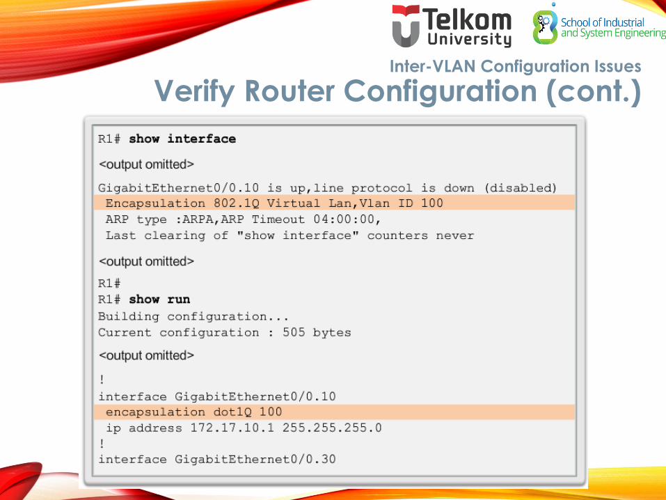
Inter-VLAN Configuration Issues
Verify Router Configuration (cont.)

• When using legacy inter-VLAN routing, ensure that the router has the correct IP address and mask on the interfaces connecting to the switch.
• Ensure that the network devices are configured with the correct IP address and mask.
• In the router, use the ip address command to fix any erroneous IP assignments.
• In the PCs, refer to the installed operating system documentation to properly change IP information.
IP Addressing Issues
Errors with IP Address and Subnet Masks

• Use the show ip interface command to verify if the correct IP address is configured in the router.
• Use the show running-config when troubleshooting router-related problems.
• When troubleshooting addressing issues, ensure that the subinterface is configured with the correct address for that VLAN.
• Subinterface IDs are often configured to match the VLAN number, which makes it easier to manage inter-VLAN configuration, but this is not a requirement.
IP Addressing Issues
Verifying IP Address and Subnet Mask Configuration Issues

3.3 LAYER 3 SWITCHING

• Layer 3 switches usually have packet-switching throughputs in the millions of packets per second (pps).
• All Catalyst multilayer switches support the following types of Layer 3 interfaces:
• Routed port
• Switch virtual interface (SVI)
• High-performance switches, such as the Catalyst 6500 and Catalyst 4500, are able to perform most of the router’s functions.
• Several models of Catalyst switches require enhanced software for specific routing protocol features.
Layer 3 Switching Operation and Configuration
Introduction to Layer 3 Switching

• Today’s routing has become faster and cheaper and can be performed at hardware speed.
• Routing can be transferred to core and distribution devices with little to no impact on network performance.
• Many users are in separate VLANs, and each VLAN is usually a separate subnet. This implies that each distribution switch must have IP addresses matching each access switch VLAN.
• Layer 3 (routed) ports are normally implemented between the distribution and the core layer. This model is less dependent on spanning tree, because there are no loops in the Layer 2 portion of the topology.
Layer 3 Switching Operation and Configuration
Inter-VLAN Routing with Switch Virtual Interfaces

• By default, an SVI is created for the default VLAN (VLAN 1). This allows for remote switch administration.
• Any additional SVIs must be created by the administrator.
• SVIs are created the first time the VLAN interface configuration mode is entered for a particular VLAN SVI.
• Enter the interface vlan 10 command to create an SVI named VLAN 10.
• The VLAN number used corresponds to the VLAN tag associated with data frames on an 802.1Q encapsulated trunk.
• When the SVI is created, ensure that the specific VLAN is present in the VLAN database.
Layer 3 Switching Operation and Configuration
Inter-VLAN Routing with SVIs (Cont.)
• SVIs advantages include:
• Much faster than router-on-a-stick, because everything is hardware-switched and routed.
• No need for external links from the switch to the router for routing.
• Not limited to one link. Layer 2 EtherChannels can be used between the switches to get more bandwidth.
• Latency is much lower, because it does not need to leave the switch.
Layer 3 Switching Operation and Configuration
Inter-VLAN Routing with SVIs (Cont.)

• A routed port is a physical port that acts similarly to an interface on a router.
• Routed ports are not associated with any VLANs.
• Layer 2 protocols, such as STP, do not function on a routed interface.
• Routed ports on a Cisco IOS switch do not support subinterfaces.
• To configure routed ports, use the no switchport interface configuration mode command.
• Note: Routed ports are not supported on Catalyst 2960 Series switches.
Layer 3 Switching Operation and Configuration
Inter-VLAN Routing with Routed Ports

• The Cisco Switch Database Manager (SDM) provides multiple templates for the Cisco Catalyst 2960 switch.
• The SDM lanbase-routing template can be enabled to allow the switch to route between VLANs and to support static routing.
• Use the show sdm prefer command to verify which template is in use.
• The SDM template can be changed in global configuration mode with the sdm prefer command.
Layer 3 Switching Operation and Configuration
Configuring Static Routes on a Catalyst 2960

To troubleshoot Layer 3 switching issues, verify the following for accuracy:
• VLANs
• VLANs must be defined across all the switches.
• VLANs must be enabled on the trunk ports.
• Ports must be in the right VLANs.
• SVIs
• SVIs must have the correct IP address or subnet mask.
• SVIs must be up.
• SVIs must match with the VLAN number.
Troubleshooting Layer 3 Switching
Layer 3 Switch Configuration Issues

To troubleshoot Layer 3 switching issues, verify the following for accuracy:
• Routing
• Routing must be enabled.
• Each interface or network should be added to the routing protocol.
• Hosts
• Hosts must have the correct IP address or subnet mask.
• Hosts must have a default gateway associated with an SVI or routed port.
Troubleshooting Layer 3 Switching
Layer 3 Switching Configuration Issues (Cont.)

CHAPTER 3: SUMMARY
This chapter described and explained the following concepts:
• Inter-VLAN routing, the process of routing traffic between different VLANs, using either a dedicated router or a multilayer switch
• Legacy, router-on-a-stick, and multilayer switch inter-VLAN routing
• Layer 3 switching, SVIs, and routed ports
• Troubleshooting inter-VLAN routing with a router or a Layer 3 switch
• Common errors involving VLAN, trunk, Layer 3 interface, and IP address configurations

CHAPTER 5: SUMMARY

TERIMA KASIH
Thank you very much for your kind attention