chapter 8 rmon (remote network monitoring) chapter 8 network management: principles and practice ©...
TRANSCRIPT

Chapter 8
RMON(Remote Network Monitoring)
Chapter 8
Network Management: Principles and Practice© Mani Subramanian 2000
8-1

Notes
Remote Monitoring
• RMON Probe• Data gatherer - a physical device
• Data analyzer• Processor that analyzes data
• RMON - Remote Network Monitoring
DataAnalyzer
RMONProbe
BACKBONENETWORK
SNMPTraffic
SNMPTraffic
LAN
RouterRouter
Chapter 8
Network Management: Principles and Practice© Mani Subramanian 2000
8-2

RMON RFCs• RFC 3577 (Informational) (August 2003) - Introduction
to the Remote Monitoring (RMON) Family of MIB Modules
• RFC 2819 (STD 59) (May 2000) - Remote Network Monitoring Management Information Base
– Obsoletes: RFC 1757 (February 1995)• Obsoletes: RFC 1271 (November 1991)
• RFC 4502 (Proposed STD) (May 2006) - Remote Network Monitoring Management Information Base Version 2
– Obsoletes: RFC 2021 (January 1997)
• RFC 3395 (Proposed STD) (September 2002) - Remote Network Monitoring MIB Protocol Identifier Reference Extensions
– Updates: RFC 2895 (Draft STD) (August 2000)• Obsoletes: RFC 2074 (January 1997)
• RFC 2896 (Informational) (August 2000) - Remote Network Monitoring MIB Protocol Identifier Macros
• RFC 1513 (Proposed STD) (September 1993) - Token Ring Extensions to the Remote Network Monitoring MIB
• RFC 2613 (Proposed STD) (June 1999) - Remote Network Monitoring MIB Extensions for Switched Networks Version 1.0
8-3

Network with RMONs
FDDIBackbone Network
Remote Token Ring LANNMS
Router Bridge
Token RingProbe
EthernetProbe
Local LAN
Figure 8.1 Network Configuration with RMONs
Router withRMON
Router
Remote FDDI LAN
FDDI Probe
Chapter 8
Network Management: Principles and Practice© Mani Subramanian 2000
8-4
Notes• RMON is embedded in a router for monitoring the remote FDDI LAN • Analysis done in NMS

Remote Network Management Goals[RFC 2819/STD 59]
• Off-line Operation: A probe can be configured to perform diagnostics and collect statistics continuously, even when communication with the NMS may not be possible or efficient. The probe may notify the NMS when an exceptional condition occurs.
• Proactive Monitoring: Given the resources available on the monitor, it is helpful for it continuously to run diagnostics and to log network performance. The monitor can notify the NMS of a failure and can store historical statistical information about it. This historical information can be played back by the NMS for further diagnosis into the cause of the problem.
• Problem Detection and Reporting: The monitor can be configured to recognize conditions, most notably error conditions, and continuously to check for them. When one of these conditions occurs, the event may be logged, and NMSs may be notified.
• Value Added Data: Because an RMON device is dedicated exclusively to NM functions, and because it is located directly on the monitored portion of the network, it can add significant value to the data it collects. For instance, by highlighting those hosts on the network that generate the most traffic or errors, the probe can give the NMS precisely the information it needs to solve a class of problems.
• Multiple Managers: An organization may have multiple NMSs for different units of the organization, for different functions (e.g. engineering and operations), and in an attempt to provide disaster recovery. Because environments with multiple NMSs are common, the RMON device has to deal with more than one NMS, potentially using its resources concurrently.
8-5

Notes
RMON Benefits
• Monitors and analyzes locally and relays data → Less load on the network (solicited and unsolicited)
• Needs no direct visibility of agents by NMS → More reliable information (polling is local)
• Permits monitoring on a more frequent basis → Faster fault diagnosis (prevent or react to a fault)
• Increases productivity for administrators (study report)and network availability to users
Chapter 8
Network Management: Principles and Practice© Mani Subramanian 2000
8-6
• Unsolicited: if abnormal condition (e.g., heavy packetloss) → Send alarm to NMS
• Case study: under heavy traffic and long-distancecommunication, packets are lost:
→ NMS gets no response for pings → NMS assumes the device (agent) is down
(wrong interpretation)

Control of Remote Monitors• Remote monitor is implemented either as:
– A dedicated device– A function available on a system
• RMON MIB contains features that support extensive control from the NMS. These features fall into 2 general categories:– Configuration: a remote monitor needs to be configured
for data collection. RMON MIB is organized into a number of functional groups. Within each group, there may be one or more control tables and one or more data tables.
• A control table: is typically read-write, and contains parameters that describe the data in a data table
• A data table: is typically read-only• At configuration time, an NMS sets the appropriate control
parameters (add a new row or modify an existing row) to configure the RMON to collect the desired data.
• To modify any parameters in a control table, it is necessary to first invalidate the control entry (row) → deletion of this row and associated rows in data tables.
– Action Invocation: is the use of SNMP Set operation to issue a command.
• An object is used to represent a command• A specific action is taken if the object is set to a specific
value.• In general, these objects represent states.• An action is performed if the NMS changes a state (i.e.,
value)
8-7

Resource Sharing Among Multiple NMSs [RFC 2819/STD 59]
• When multiple management stations wish to use functions that compete for a finite amount of resources on a device, a method to facilitate this sharing of resources is required. Potential conflicts include:
– Two management stations wish to simultaneously use resources that together would exceed the capability of the device.
– A management station uses a significant amount of resources for a long period of time.
– A management station uses resources and then crashes, forgetting to free the resources so others may use them.
• A mechanism is provided for each management station initiated function in this MIB to avoid these conflicts and to help resolve them when they occur.
• Each function has a label identifying the initiator (owner) of the function (i.e., associated with each control table is a columnar object that identifies the owner of a particular row). This label is set by the initiator to provide for the following possibilities:
– A management station may recognize resources it owns and no longer needs.
– A network operator can find the management station that owns the resource and negotiate for it to be freed.
– A network operator may decide to unilaterally free resources another network operator has reserved.
– Upon initialization, a management station may recognize resources it had reserved in the past. With this information it may free the resources if it no longer needs them.
8-8

RMON Textual Conventions [RFC 2819/STD 59]
OwnerString ::= TEXTUAL-CONVENTIONSTATUS currentDESCRIPTION "This data type is used to model an
administratively assigned name of the owner of a resource. Implementations must accept values composed of well-formed NVT ASCII sequences. In addition, implementations should accept values composed of well-formed UTF-8 sequences. It is suggested that this name contain one or more of the following: IP address, management station name, network manager's name, location, or phone number. In some cases the agent itself will be the owner of an entry. In these cases, this string shall be set to a string starting with 'monitor'. SNMP access control is articulated entirely in terms of the contents of MIB views; access to a particular SNMP object instance depends only upon its presence or absence in a particular MIB view and never upon its value or the value of related object instances. Thus, objects of this type afford resolution of resource contention only among cooperating managers; they realize no access control function with respect to uncooperative parties.“
SYNTAX OCTET STRING (SIZE (0..127))
8-9
Notes
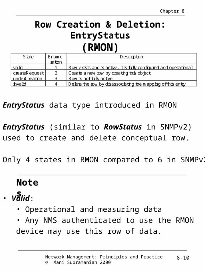
Row Creation & Deletion: EntryStatus(RMON)
State Enume-ration
Description
valid 1 Row exists and is active. It is fully configured and operationalcreateRequest 2 Create a new row by creating this objectunderCreation 3 Row is not fully activeinvalid 4 Delete the row by disassociating the mapping of this entry
• EntryStatus data type introduced in RMON
• EntryStatus (similar to RowStatus in SNMPv2)
used to create and delete conceptual row.
• Only 4 states in RMON compared to 6 in SNMPv2
Chapter 8
Network Management: Principles and Practice© Mani Subramanian 2000
8-10
• Valid:• Operational and measuring data• Any NMS authenticated to use the RMON
device may use this row of data.
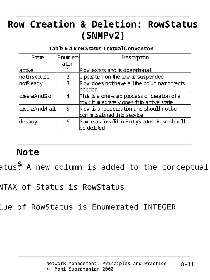
Row Creation & Deletion: RowStatus(SNMPv2)
Notes
Table 6.4 RowStatus Textual Convention
State Enumer-ation
Description
active 1 Row exists and is operationalnotInService 2 Operation on the row is suspendednotReady 3 Row does not have all the columnar objects
neededcreateAndGo 4 This is a one-step process of creation of a
row; immediately goes into active statecreateAndWait 5 Row is under creation and should not be
commissioned into servicedestroy 6 Same as Invalid in EntryStatus. Row should
be deleted
• Status: A new column is added to the conceptual table
• SYNTAX of Status is RowStatus
• Value of RowStatus is Enumerated INTEGER
Network Management: Principles and Practice© Mani Subramanian 2000
8-11

Row Addition, Modification and Deletion
• Row Addition:– If a management station attempts to create a new
row, and the index object value or values do not already exist, the row is created with status object value of “createRequest(2)”
– Immediately after completing the create operation, the agent sets the status object value to “underCreation(3)”
– Rows shall exist in the “underCreation(3)” state until the management station is finished creating all of the rows that it desires for its configuration. The management station sets the status object value in each of the created rows to “valid(1)”
– If an attempt is made to create a new row, with a “createRequest(2)”status, and the row already exists, an error will be returned.
• Row Modification and Deletion– A row is deleted by setting the status object value for
that row to “invalid(4)”– The owner of the row can then delete it by issuing a
SetRequest PDU– A row can be modified by first invalidating the row
and then providing the row with new parameter values.
8-12
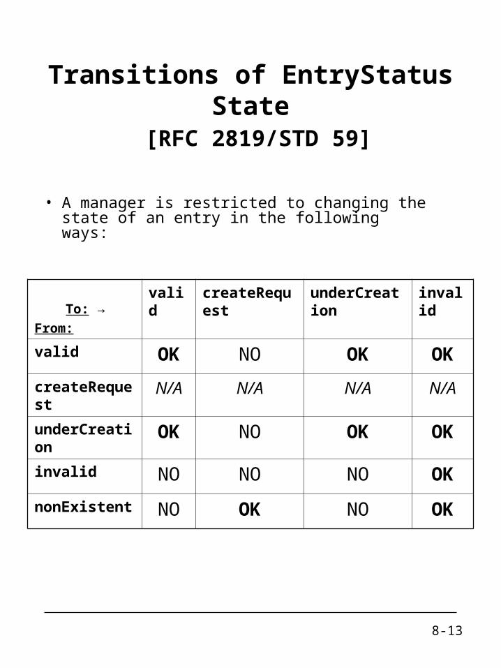
Transitions of EntryStatus State [RFC 2819/STD 59]
• A manager is restricted to changing the state of an entry in the following ways:
To: →From:
valid createRequest underCreation invalid
valid OK NO OK OK
createRequest N/A N/A N/A N/A
underCreation OK NO OK OK
invalid NO NO NO OK
nonExistent NO OK NO OK
8-13

Conventions for Good and Bad Packets [RFC 2819/STD 59]
• Good packets are error-free packets that have a valid frame length. For example, on Ethernet, good packets are error-free packets that are between 64 octets long and 1518 octets long. They follow the form defined in IEEE 802.3 section 3.2.all.
• Bad packets are packets that have proper framing and are therefore recognized as packets, but contain errors within the packet or have an invalid length. For example, on Ethernet, bad packets have a valid preamble and SFD, but have a bad CRC, or are either shorter than 64 octets or longer than 1518 octets.
8-14

RMON MIB
rmonConformance (20)
probeConfig (19)
usrHistory (18)
rmon (mib-2 16)
statistics (1)
history (2)
alarm (3)
host (4)
hostTopN (5)
matrix (6)
filter (7)
capture (8)
event (9)
Figure 8.2 RMON Group
a1Matrix (17)
a1Host (16)
n1Matrix (15)
n1Host (14)
addressMap (13)
protocolDist (12)
protocolDir (11)
Token Ring (10)
RMON1 Extension
RM
ON
1
RM
ON
2
Notes• All of the groups in the RMON MIB are optional
• RMON1: Ethernet RMON groups (rmon 1 - rmon 9)
• RMON1: Extension: Token ring extension (rmon 10)
• RMON2: Higher layers (3-7) groups (rmon 11 - rmon 20)
Chapter 8
Network Management: Principles and Practice© Mani Subramanian 2000
8-15

RMON Groups and Functions
Host and Conversation Statistics
Token Ring Statistics
Ethernet Statistics
Filter Group
RemotelyMonitoredNetwork
DataGathering
PacketFiltering
ChannelFiltering
PacketCapture
NetworkManager
AlarmGeneration
EventGeneration
HostStatistics
HostTopNStatistics
EthernetStatistics
EthernetHistory
Token RingStatistics
Token RingHistory
MatrixStatistics
HistoryControl
HistoryControl
Figure 8.3 RMON1 Groups and Functions
Notes• Probe gathers data• Functions
• Statistics on Ethernet, token ring, and hosts & conversations• Filter group filters data prior to capture of data• Generation of alarms and events
Chapter 8
Network Management: Principles and Practice© Mani Subramanian 2000
8-16

RMON1 MIB Groups & TablesGroup OID Function Tables Statistics rmon 1 Link level statistics -etherStatsTable
-etherStats2Table History rmon 2 Periodic statistical data
collection and storage for later retrieval
-historyControlTable -etherHistoryTable -historyControl2Table -etherHistory2Table
Alarm rmon 3 Generates events when the data sample gathered crosses pre-established thresholds
-alarmTable
Host rmon 4 Gathers statistical data on hosts -hostControlTable -hostTable -hostTimeTable -hostControl2Table
HostTopN rmon 5 Computes the top N hosts on the respective categories of statistics gathered
-hostTopNControlTable -hostTopNTable
Matrix rmon 6 Statistics on traffic between pair of hosts
-matrixControlTable -matrixSDTable -matrixDSTable -matrixControl2Table
Filter rmon 7 Filter function that enables capture of desired parameters
-filterTable -channelTable -filter2Table -channel2Table
Packet Capture
rmon 8 Packet capture capability to gather packets after they flow through a channel
-buffercontrolTable -captureBufferTable
Event rmon 9 Controls the generation of events and notifications
-eventTable
Token Ring
rmon 10 See Table 8.3 See Table 8.3
Notes
Chapter 8
• Ten groups divided into three categories• Statistics groups (rmon 1, 2, 4, 5, 6, and 10))• Event reporting groups (rmon 3 and 9)• Filter and packet capture groups (rmon 7 and 8)
• Groups with “2” in the name are enhancements with RMON2
Network Management: Principles and Practice© Mani Subramanian 2000
8-17

Control and Data Tables
dataIndex
dataIndex
controlTableSize
controlTable
controlEntry
controlOwner
controlStatus
dataEntry
dataAddlIndex
Figure 8.4 Relationship between Control and Data Tables
Note on Indices: Indices marked in bold letter Value of dataIndex same as value of controlIndex
controlDataSource
controlOther
controlTableSize
controlOwner
controlStatus
controlDataSource
controlOther
dataOther
dataAddlIndex
dataOther
dataIndex
dataAddlIndex
dataOther
dataIndex
dataAddlIndex
dataOther
dataTable
controlIndex
controlIndex
Chapter 8
Notes• Control table used to set the instances of data rows in the data table
• Values of data index and control index are the same
Network Management: Principles and Practice© Mani Subramanian 2000
8-18

Example: Matrix Control and SD Tables
matrixSDDestinationAddress =193.5.8.20
matrixSDSource
Address =172.15.8.11
matrixSDSource
Address =172.15.8.11
matrixControl
TableSize =10
matrixControlTable
matrixControlEntry
matrixControl
Owner ="Bob"
matrixControl
Status = 1
matrixSDEntry
matrixSDDestinationAddress =192.7.8.11
Figure 8.4 Relationship between Control and Data Tables
Note on Indices: Indices marked in bold letter Value of dataIndex same as value of controlIndex
matrixControl
DataSource=ifIndex.1
matrixControlLastDeleteTime
= 1000
matrixControl
TableSize =10
matrixControl
Owner ="Bob"
matrixControl
Status = 1
matrixControl
DataSource=ifIndex.2
matrixControlLastDeleteTime= 100050
matrixSD
Index =1
matrixSDDestinationAddress =199.5.8.20
matrixSD
Index =1
matrixSDSource
Address =172.16.8.16
matrixSD
Index =2
matrixSDSource
Address =172.16.8.20
matrixSDDestinationAddress =193.5.8.20
matrixSD
Index =2
matrixSDTable
matrixControl
Index = 1
matrixControl
Index = 2
matrixSD
Pkts =
matrixSD
Pkts =
matrixSD
Pkts =
matrixSD
Pkts =
Chapter 8
Notes• matrixSDTable is the source-destination table
• controlDataSource identifies the source of the data
• controlTableSize identifies entries associated with the data source
• controlOwner is creator of the entry
Network Management: Principles and Practice© Mani Subramanian 2000
8-19

Ethernet Statistics Group• Contains statistics measured by the probe for each
monitored Ethernet interface on a device.
• These statistics take the form of free running counters that start from zero when a valid entry is created.
• Each etherStatsEntry contains statistics for one Ethernet interface.
• The probe must create one etherStats entry for each monitored Ethernet interface on the device.
• Data includes statistics on packet types, sizes, and errors.
• Capability to gather statistics on collisions of the Ethernet segment (estimation).
• Number of collisions can be used to generate an alarm when it exceeds a set threshold value.
8-20

Ethernet Statistics Group(cont.)
EtherStatsEntry ::= SEQUENCE { etherStatsIndex Integer32, etherStatsDataSource OBJECT IDENTIFIER, etherStatsDropEvents Counter32, etherStatsOctets Counter32, etherStatsPkts Counter32, etherStatsBroadcastPkts Counter32, etherStatsMulticastPkts Counter32, etherStatsCRCAlignErrors Counter32, etherStatsUndersizePkts Counter32, etherStatsOversizePkts Counter32, etherStatsFragments Counter32, etherStatsJabbers Counter32, etherStatsCollisions Counter32, etherStatsPkts64Octets Counter32, etherStatsPkts65to127Octets Counter32, etherStatsPkts128to255Octets Counter32, etherStatsPkts256to511Octets Counter32, etherStatsPkts512to1023Octets Counter32, etherStatsPkts1024to1518Octets Counter32, etherStatsOwner OwnerString, etherStatsStatus EntryStatus }• etherStatsDataSource → This object identifies the source of
the data that this etherStats entry is configured to analyze. (e.g., ifIndex.1)
8-21

History Group• Consists of two subgroups:
– History control group:• Controls the periodic statistical sampling of data
from various types of networks
– History (data) group:• Tracks the overall trend in the volume of traffic.
• Control table (historyControlTable):– Stores configuration entries comprising
interface, polling period, etc.– Contains one entry for each sample– If the probe keeps track of the time of day, it
should start the first sample of the history at a time such that when the next hour of the day begins, a sample is started at that instant
– Short-term and long-term intervals may be specified (two entries). Defaults → 30 seconds and 30 minutes (respectively)
8-22

History Control TableHistoryControlEntry ::= SEQUENCE { historyControlIndex Integer32, historyControlDataSource OBJECT IDENTIFIER, historyControlBucketsRequested Integer32, historyControlBucketsGranted Integer32, historyControlInterval Integer32, historyControlOwner OwnerString, historyControlStatus EntryStatus }
• historyControlBucketsRequested → The requested number of discrete time intervals
• historyControlBucketsGranted → The number of discrete sampling intervals
• historyControlInterval → The interval in seconds over which the data is sampled for each bucket. This interval can be set to any number of seconds between 1 and 3600 (1 hour).
8-23

Ethernet History Group• Data table (etherHistoryTable):
– Records periodic statistical samples from a network and stores them for later retrieval
– Once samples are taken, their data is stored in an entry in a media-specific table
– Each such entry defines one sample, and is associated with the historyControlEntry.
– Each value is a cumulative sum during a sampling period
• Data objects defined:– Dropped events, number of octets and
packets, different types of errors, fragments, collisions, and utilization.
8-24

Ethernet History Table
EtherHistoryEntry ::= SEQUENCE { etherHistoryIndex Integer32, etherHistorySampleIndex Integer32, etherHistoryIntervalStart TimeTicks, etherHistoryDropEvents Counter32, etherHistoryOctets Counter32, etherHistoryPkts Counter32, etherHistoryBroadcastPkts Counter32, etherHistoryMulticastPkts Counter32, etherHistoryCRCAlignErrors Counter32, etherHistoryUndersizePkts Counter32, etherHistoryOversizePkts Counter32, etherHistoryFragments Counter32, etherHistoryJabbers Counter32, etherHistoryCollisions Counter32, etherHistoryUtilization Integer32 }
• etherHistoryIndex → has same value as historyControlIndex.
• etherHistorySampleIndex → uniquely identifies the particular sample among all the ones with the same historyControlEntry.
• etherHistoryIntervalStart → the value of sysUpTime at the start of the interval over which this sample was measured.
8-25

Alarm Group• The Alarm Group requires the implementation of
the Event group.
• Periodically takes statistical samples on specified variables in the probe and compares them with a preconfigured threshold.
• The group contains an alarmTable with a list of configuration entries that define alarm parameters: variable, polling period, and threshold.
• If a sample of monitored variable ≥ rising_threshold or ≤ falling_threshold → event generated
• Rising and falling thresholds are specified → generates one event as a threshold is crossed in the appropriate direction and no more events are generated until the opposite threshold is crossed.
• Sampling type is either the absolute or delta value. (e.g., 1 gigaoctet in the former and 10000 packets in a 10-second interval in the latter).
8-26

Alarm TableAlarmEntry ::= SEQUENCE { alarmIndex Integer32, alarmInterval Integer32, alarmVariable OBJECT IDENTIFIER, alarmSampleType INTEGER, alarmValue Integer32, alarmStartupAlarm INTEGER, alarmRisingThreshold Integer32, alarmFallingThreshold Integer32, alarmRisingEventIndex Integer32, alarmFallingEventIndex Integer32, alarmOwner OwnerString, alarmStatus EntryStatus }
• alarmInterval → The interval in seconds over which the data is sampled and compared with the rising and falling thresholds.
• alarmVariable → The object identifier of the particular variable to be sampled.
• alarmSampleType → absoluteValue(1), deltaValue(2)
• alarmValue → The value of the statistic during the last sampling period.
– This is the value that is compared with the rising and falling thresholds.
– If (sample type is deltaValue) → alarmValue = difference between the samples at the beginning and end of the period.
– If (sample type is absoluteValue) → alarmValue = sampled value at the end of the period.
8-27

Host Group• Contains information about the hosts on the
network.
• Compiles a list of hosts by looking at the good packets traversing the network and extracting the source and destination MAC addresses.
• Maintains statistics on these hosts.
• Comprises three tables:– hostControlTable: controls interfaces on which
data gathering is done.– hostTable: contains statistics about the hosts
(indexed by the a control index and host’s MAC address).
– hostTimeTable: contains the same data as hostTable, but stored in time order of its discovery.
• Index values are more predictable (1 → table_size)
• Used for fast download of table content and fast discovery of new hosts in the system
8-28

HostTopN Group• Requires the implementation of the Host group.
• Generates reports ranking the top N hosts in selected statistics categories.
• The available statistics are samples of one of their base statistics, over an interval specified by the management station.
• The management station selects how many such hosts are reported.
• hostTopNControlTable is used to initiate generation of a report.
• The management station may select the parameters of such a report, such as which interface, which statistic, how many hosts, and the start and stop times of the sampling.
• When the report is prepared, entries are created in the hostTopNTable.
8-29

HostTopN Group (Cont.)hostTopNControlTable hostTopNRateBase OBJECT-TYPE SYNTAX INTEGER { hostTopNInPkts(1), hostTopNOutPkts(2), hostTopNInOctets(3), hostTopNOutOctets(4), hostTopNOutErrors(5), hostTopNOutBroadcastPkts(6), hostTopNOutMulticastPkts(7) }
hostTopNTable hostTopNIndex OBJECT-TYPE SYNTAX Integer32 (1..65535) MAX-ACCESS read-only STATUS current DESCRIPTION “An index that uniquely identifies an entry in the hostTopN table among
those in the same report. This index is between 1 and N, where N is the number of entries in this table…”
hostTopNRate OBJECT-TYPE SYNTAX Integer32 MAX-ACCESS read-only STATUS current DESCRIPTION “The amount of change in the selected variable during this sampling
interval. The selected variable is this host's instance of the object selected by hostTopNRateBase.”
8-30

Notes
Host Top N Group ExampleHostTopN
0 100 200 300 400
Host 10
Host 9
Host 8
Host 7
Host 6
Host 5
Host 4
Host 3
Host 2
Host 1
Giga Octets
Figure 8.5 HostTop-10 Output Octets
Chapter 8
Network Management: Principles and Practice© Mani Subramanian 2000
8-31

Matrix Group• Stores statistics on conversations between
pairs of hosts.
• An entry is created for each conversation that the probe detects.
• It creates new entries based on information received in good packets.
• Contains three tables:– matrixControlTable: controls the information to
be gathered.– matrixSDTable: keeps track of the source to
destination conversations.– matrixDSTable: keeps track of the destination
to source conversations.
8-32

Matrix Group (Cont.)MatrixSDEntry ::= SEQUENCE { matrixSDSourceAddress OCTET
STRING, matrixSDDestAddress OCTET STRING, matrixSDIndex Integer32, matrixSDPkts Counter32, matrixSDOctets Counter32, matrixSDErrors Counter32 }
• matrixSDPkts → The number of packets transmitted from the source address (SA) to the destination address (DA) including bad packets.
• matrixSDOctets → The number of octets (excluding framing bits but including FCS octets) contained in all packets transmitted from SA to DA.
• matrixSDErrors → The number of bad packets transmitted from SA to DA.
8-33

Filter Group
filterChannelIndex
= 2
filterIndex= 2
filterIndex= 1
channelIndex =1
channelTable
channelEntry
channelIfIndex = 1
channelAcceptType
filterEntry
filterChannelIndex
= 1
Note on Indices: Indices marked in bold letter Value of filterChannelIndex same as value of channelIndex
channelDataControl
channelIndex = 2
channelIfIndex
channelAcceptType
channelDataControl
FilterParameters
filterChannelIndex
= 1
FilterParameters
filterIndex= 3
FilterParameters
filterIndex= 4
filterChannelIndex
= 2
FilterParameters
filterTable
OtherChannel
Parameters
OtherChannel
Parameters
Chapter 8
Notes• Filter group used to capture packets defined by logical expressions• Channel is a stream of data captured based on a logical expression • Filter table allows packets to be filtered with an arbitrary filter expression• A row in the channel table associated with multiple rows in the filter table
Network Management: Principles and Practice© Mani Subramanian 2000
8-34

Filter Group (Cont.)
• Each filter associated with a channel is OR'ed with the others.
• Within a filter, any bits checked in the data and status are AND'ed with respect to other bits in the same filter.
• The NotMask allows for checking for inequality.
• The channelAcceptType object allows for inversion of the whole equation.
8-35

Filter TableFilterEntry ::= SEQUENCE { filterIndex Integer32, filterChannelIndex Integer32, filterPktDataOffset Integer32, filterPktData OCTET STRING, filterPktDataMask OCTET STRING, filterPktDataNotMask OCTET STRING, filterPktStatus Integer32, filterPktStatusMask Integer32, filterPktStatusNotMask Integer32, filterOwner OwnerString, filterStatus EntryStatus }
• filterPktDataOffset → Offset from the beginning of each packet where a match of packet data will be attempted
• filterPktData → Data that is to be matched with the input packet
• filterPktDataMask → The mask that is applied to the match process. if the associated filterPktData object is longer than this mask, this mask is conceptually extended with '1' bits.
• filterPktDataNotMask → The inversion mask that is applied to the match process. if the associated filterPktData object is longer than this mask, this mask is conceptually extended with '0' bits.
8-36

Channel TableChannelEntry ::= SEQUENCE { channelIndex Integer32, channelIfIndex Integer32, channelAcceptType INTEGER, channelDataControl INTEGER, channelTurnOnEventIndex Integer32, channelTurnOffEventIndex Integer32, channelEventIndex Integer32, channelEventStatus INTEGER, channelMatches Counter32, channelDescription DisplayString, channelOwner OwnerString, channelStatus EntryStatus }
• channelAcceptType → acceptMatched(1), or acceptFailed(2) [i.e., packets will be accepted if they fail to match associated filters]
• channelDataControl → on(1) or off(2)
• channelTurnOnEventIndex → event configured to turn the associated channelDataControl on when the event is generated
• channelEventIndex → event to be generated when the associated channelDataControl is on and a packet is matched
• channelEventStatus → eventReady(1), eventFired(2), or eventAlwaysReady(3)
• channelMatches → number of times this channel has matched a packet (this is updated even when channelDataControl = off).
8-37

Packet Capture Group
CaptureBufferTable(one entryper
channel)
Chapter 8
Filter Table(many
for each
channel)
ChannelTable
Notes
• Packet Capture Group requires implementationof the Filter Group.
• Packet capture group is a post-filter group.
• Buffer control table used to select channels.
• Captured data stored in the capture buffer table.
Network Management: Principles and Practice© Mani Subramanian 2000
8-38

Buffer Control TableBufferControlEntry ::= SEQUENCE { bufferControlIndex Integer32, bufferControlChannelIndex Integer32, bufferControlFullStatus INTEGER, bufferControlFullAction INTEGER, bufferControlCaptureSliceSize Integer32, bufferControlDownloadSliceSize Integer32, bufferControlDownloadOffset Integer32, bufferControlMaxOctetsRequested Integer32, bufferControlMaxOctetsGranted Integer32, bufferControlCapturedPackets Integer32, bufferControlTurnOnTime TimeTicks, bufferControlOwner
OwnerString, bufferControlStatus EntryStatus }
• bufferControlFullStatus → spaceAvailable(1) or full(2)
• bufferControlFullAction → lockWhenFull(1), or wrapWhenFull(2) [i.e., FIFO]
8-39

Event Group
• Controls the generation and notification of events from this device.
• Each entry in the eventTable describes the parameters of the event that can be triggered.
• Each event entry is fired by an associated condition located elsewhere in the MIB.
• An event entry may also be associated with a function elsewhere in the MIB that will be executed when the event is generated.
• Both rising and falling alarms can be specified in the eventTable associated with the group.
• In addition to transmitting events, the system optionally maintains a log in logTable.
8-40

Notes
RMON TR Extension Groups (RFC 1513)
Chapter 8
Token Ring Group Function Tables Statistics Current utilization
and error statistics of Mac Layer
tokenRingMLStatsTable tokenRingMLStats2Table
Promiscuous Statistics Current utilization and error statistics of promiscuous data
tokenRingPStatsTable tokenRingPStats2Table
Mac-Layer History Historical utilization and error statistics of Mac Layer
tokenRingMLHistoryTable
Promiscuous History Historical utilization and error statistics of promiscuous data
tokenRingPHistoryTable
Ring Station Station statistics ringStationControlTable ringStationTable ringStationControl2Table
Ring Station Order Order of the stations
ringStationOrderTable
Ring Station Configuration
Active configuration of ring stations
ringStationConfigControlTable ringStationConfigTable
Source Routing Utilization statistics of source routing information
sourceRoutingStatsTable sourceRoutingStats2Table
• Two statistics groups and associated history groups:• MAC layer (Statistics group) collects TR parameters.• Promiscuous Statistics group collects packets promiscuously on sizes and types of packets.
• Three groups associated with the stations.• Source Routing group gathers statistics from sourcerouting information.
Network Management: Principles and Practice© Mani Subramanian 2000
8-41

Notes
RMON2(RFC 4502)
• Applicable to Layers 3 and above
• Functions similar to RMON1
• Enhancement to RMON1
• Defined conformance and compliance
Chapter 8
Network Management: Principles and Practice© Mani Subramanian 2000
8-42

RMON2 MIBTable 8.4 RMON2 MIB Groups and Tables
Group OID Function Tables Protocol Directory
rmon 11 Inventory of protocols protocolDirTable
Protocol Distribution
rmon 12 Relative statistics on octets and packets
protocolDistControlTable protocolDistStatsTable
Address Map rmon 13 Mac address to network address on the interfaces
addressMapControlTable addressMapTable
Network Layer Host
rmon 14 Traffic data from and to each host
nlHostControlTable nlHostTable
Network Layer Matrix
rmon 15 Traffic data from each pair of hosts
nlMatrixControlTable nlMatrixSDTable nlMatrixDSTable nlMatrixTopNControlTable nlMatrixTopNTable
Application Layer Host
rmon 16 Traffic data by protocol from and to each host
alHostTable
Application Layer Matrix
rmon 17 Traffic data by protocol between pairs of hosts
alMatrixSDTable alMatrixDSTable alMatrixTopNControlTable alMatrixTopNTable
User History Collection
rmon 18 User-specified historical data on alarms and statistics
usrHistoryControlTable usrHistoryObjectTable usrHistoryTable
Probe Configuration
rmon 19 Configuration of probe parameters
serialConfigTable netConfigTable trapDestTable serialConnectionTable
RMON Conformance
rmon 20 RMON2 MIB Compliances and Compliance Groups
See Section 8.4.2
Chapter 8
Notes
Network Management: Principles and Practice© Mani Subramanian 2000
8-43

Network-Layer visibility
Chapter 8
• In RMON1, an RMON probe can:• monitor traffic on LANs to which it is attached.• capture all of the MAC-level frames.• read source and destination MAC addresses (SA and DA).• provide info about MAC traffic between hosts.
• If a router is attached to a LAN, an RMON1 probecan only monitor the total traffic to/from the router→ Can’t determine the ultimate SA or DA.
• RMON2 probe is capable of reading the header ofnetwork-layer protocol (e.g., IP)→ Can analyze traffic passing through a router and determine the ultimate SA and DA.→ Can provide more info about the traffic loads on the network (e.g., for troubleshooting) → optimize traffic flow and improve performance.
8-44
Application-Level visibility
Chapter 8
• RMON2 probes are capable of seeing above the IP layer by reading higher-level headers (e.g., TCP).
• In RMON2, a NM application can generate charts and graphs depicting traffic percentage by protocols or by applications.
• Usage of the Term “Application Level” (RFC 2021)
• In this MIB, the term Application Level is used to describe a class of protocols or a capability.• This does not typically mean a protocol that is an OSI Layer 7 protocol.• Rather, it is used to identify a class of protocols that is not limited to MAC-layer and network-layer protocols, but can also include transport, session, presentation, and application-layer protocols.
8-45

New Functional Features in RMON2
Chapter 8
• Indexing with External Objects:• In RMON1, a data table can have many indices.The first index object just duplicates an index valuefrom the index object for the control table.• In RMON2, the data table uses the index objectof the control table (i.e., an external object) as oneof its indices → the data table has one less columnarobject (i.e., the previously duplicate index).
• RMON2 uses RowStatus (defined in SNMPv2) insteadof EntryStatus used in RMON1 to define status objects.
• Time Filter Indexing:• It is desirable to have the probe return values onlyfor those objects whose values have changed sincethe last poll → Use of TimeFilter.
8-46
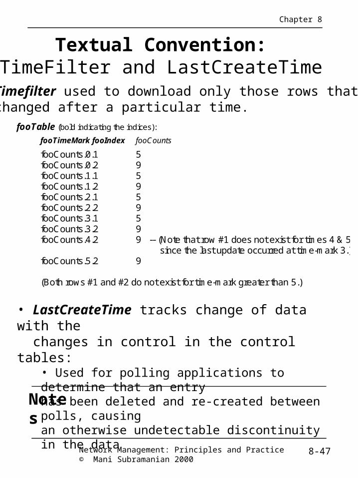
Textual Convention:TimeFilter and LastCreateTime
Chapter 8
fooTable (bold indicating the indices):
fooTimeMark fooIndex fooCounts
fooCounts.0.1 5 fooCounts.0.2 9 fooCounts.1.1 5 fooCounts.1.2 9 fooCounts.2.1 5 fooCounts.2.2 9 fooCounts.3.1 5 fooCounts.3.2 9 fooCounts.4.2 9 -- (Note that row #1 does not exist for times 4 & 5 since the last update occurred at time-mark 3.) fooCounts.5.2 9
(Both rows #1 and #2 do not exist for time-mark greater than 5.)
• Timefilter used to download only those rows that changed after a particular time.
Network Management: Principles and Practice© Mani Subramanian 2000
8-47
Notes
• LastCreateTime tracks change of data with the changes in control in the control tables:
• Used for polling applications to determine that an entryhas been deleted and re-created between polls, causingan otherwise undetectable discontinuity in the data

Protocol Directory Group(protocolDir)
Chapter 8
• A central point for storing information about typesof protocols.
• Lists the inventory of protocols the probe has thecapability of monitoring.
• Allows the addition, deletion, and configuration ofentries in this list.
• Includes a protocolDirTable that:• has one entry for each protocol for which the probecan decode and count PDUs.• covers MAC-, network-, and higher-layerprotocols.
• Includes propocolDirLastChange, which containsthe time of the last table update.
8-48

Protocol Directory Table(protocolDirTable)
Chapter 8
ProtocolDirEntry ::= SEQUENCE { protocolDirID OCTET STRING, protocolDirParameters OCTET STRING, protocolDirLocalIndex Integer32, protocolDirDescr DisplayString, protocolDirType BITS, protocolDirAddressMapConfig INTEGER, protocolDirHostConfig INTEGER, protocolDirMatrixConfig INTEGER, protocolDirOwner OwnerString, protocolDirStatus RowStatus}
• protocolDirID: contains a unique octet string fora specific protocol. It is arranged in a tree-structuredhierarchy. The root of this tree is the identifier of theMAC-level protocol. Examples: ether2: [4.0.0.0.1],ether2.ip.udp.snmp: [16.0.0.0.1.0.0.8.0.0.0.0.17.0.0.0.161]
• protocolDirParameters: A set of parameters forthe associated protocolDirID (see RFC 3395)
8-49

Protocol Distribution Group(protocolDist)
Chapter 8
• Collects the relative amounts of octets and packetsfor the different protocols detected on a network segment.
• Consists of 2 tables:• protocolDistControlTable: Controls the setup ofprotocol type distribution statistics tables. Each rowrefers to a unique interface for this probe, and controlsa number of rows of protocolDistStatsTable, onefor each protocol recognized on that interface.
• protocolDistStatsTable: includes one row for eachprotocol in protocolDirTable for which at least onepacket has been seen. It includes 2 columnar objects:
- protocolDistStatsPkts: Number of packetswithout errors received of this protocol type. - protocolDistStatsOctets: Number of octetsin packets received of this protocol type sinceit was added to the protocolDistStatsTable.
8-50

Address Map Group(addressMap)
Chapter 8
• Lists MAC address to network address bindings discoveredby the probe and what interface they were last seen on.
• Useful in node discovery and network topology applications.
• Consists of 3 scalar objects and 2 tables:
• addressMapInserts: Number of times an addressmapping entry has been inserted into the data table.
• addressMapDeletes: Number of times an addressmapping entry has been deleted from the data table.
→ Table size = addressMapInserts - addressMapDeletes
• addressMapMaxDesiredEntries: Desired maximumnumber of entries in the addressMapTable.(-1 means “any number of entries”.)
• addressMapControlTable
• addressMapTable
8-51

Address Map Tables
Chapter 8
• addressMapControlTable: controls the collectionof network layer address to physical address tointerface mappings. Each entry in this table enablesthe discovery of addresses on a new interface andthe placement of address mappings into the centraladdressMapTable.
• addressMapTable: A table of network layer addressto physical address to interface mappings. The probewill add entries to this table based on the sourceMAC and network addresses seen in packets withoutMAC-level errors. Each row stores information about:
- addressMapNetworkAddress
- addressMapSource: Interface or port on whichthe associated network address was mostrecently seen.
- addressMapPhysicalAddress: Last sourcephysical address on which the associated networkaddress was seen.
8-52

Network Layer Host Group(nlHost)
Chapter 8
• Counts the amount of traffic sent from and to eachnetwork address discovered by the probe.
• Similar to the RMON1 host group, except that nlHostgathers statistics based on network-layer address.
• Consists of 2 tables:
• hlHostControlTable: A list of higher layer(i.e. non-MAC) host table control entries.
• A separate count of inserts, deletes, andMaxDesiredEntries is kept for nlHostTableand alHostTable.
• nlHostTable: A collection of statistics for a particularnetwork layer address that has been discovered on aninterface of this device. Each row stores informationabout:
- nlHostAddress- nlHostInPkts & nlHostOutPkts- nlHostInOctets & nlHostOutOctets
8-53

Network Layer Matrix Group(nlMatrix)
Chapter 8
• Counts the amount of traffic sent between each pair ofnetwork addresses discovered by the probe.
• Similar to the RMON1 matrix group and hostTopNgroup, except that nlMatrix gathers statistics based onnetwork-layer address.
• Consists of 5 tables:
• hlMatrixControlTable• nlMatrixSDTable• nlMatrixDSTable• nlMatrixTopNControlTable• nlMatrixTopNTable
8-54

Network Layer Source/Dest. Statistics
Chapter 8
• hlMatrixControlTable: A list of higher layer(i.e. non-MAC) matrix control entries.
• A separate count of inserts, deletes, andMaxDesiredEntries is kept for nlMatrixTableand alMatrixTable.
• nlMatrixSDTable: A list of traffic matrix entries which collect statistics for conversations between twonetwork-level addresses. It is indexed by SA then DA.Each row stores information about:
- nlMatrixSDPkts- nlMatrixSDOctets
• nlMatrixDSTable: contains the same info asnlMatrixSDTable, but it is indexed by DA then SA.
8-55

Network Layer TopN Statistics
Chapter 8
• In RMON2 TopN statistics table, the ranking is ofthe traffic between pairs of hosts. (In RMON1, it isbased on individual hosts.)
• nlMatrixTopNControlTable: A set of parameters that control the creation of a report of the top N matrix entries according to a selected metric.
• nlMatrixTopNTable: A set of statistics for those network layer matrix entries that have counted the highest number of octets or packets. Each row stores information about:
- nlMatrixTopNProtocolDirLocalIndex - nlMatrixTopNSourceAddress - nlMatrixTopNDestAddress - nlMatrixTopNPktRate - nlMatrixTopNReversePktRate - nlMatrixTopNOctetRate - nlMatrixTopNReverseOctetRate
8-56

Application Layer Host Group(alHost)
Chapter 8
• The application layer host, matrix, and matrixTopNfunctions report on protocol usage at the network layeror higher.
• alHost group counts the amount of traffic, by protocol,sent from and to each network address discovered bythe probe.
• Similar to the RMON1 host group, except that alHostgathers statistics based on application-layer address.
• hlHostControlTable also controls alHostTable.
• alHostTable: A collection of statistics for a particularprotocol from a particular network address that hasbeen discovered on an interface of this device (one Index is the external object: nlHostAddress). Each rowstores information about:
- alHostInPkts & alHostOutPkts- alHostInOctets & alHostOutOctets
8-57

Application Layer Matrix Group(alMatrix)
Chapter 8
• Counts the amount of traffic, by protocol, sent between each pair of network addresses discovered by the probe.
• Similar to the RMON1 matrix group and hostTopNgroup, except that alMatrix gathers statistics based onapplication-layer address.
• hlMatrixControlTable also controls alMatrixSDTable and alMatrixDSTable.
• Consists of 4 tables:• nlMatrixSDTable• alMatrixDSTable• alMatrixTopNControlTable• alMatrixTopNTable
8-58
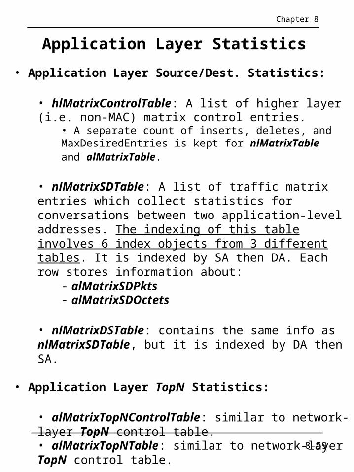
Application Layer Statistics
Chapter 8
• Application Layer Source/Dest. Statistics:
• hlMatrixControlTable: A list of higher layer(i.e. non-MAC) matrix control entries.
• A separate count of inserts, deletes, andMaxDesiredEntries is kept for nlMatrixTableand alMatrixTable.
• nlMatrixSDTable: A list of traffic matrix entries which collect statistics for conversations between two application-level addresses. The indexing of this table involves 6 index objects from 3 different tables. It is indexed by SA then DA. Each row stores information about:
- alMatrixSDPkts- alMatrixSDOctets
• nlMatrixDSTable: contains the same info asnlMatrixSDTable, but it is indexed by DA then SA.
• Application Layer TopN Statistics:
• alMatrixTopNControlTable: similar to network-layer TopN control table.• alMatrixTopNTable: similar to network-layer TopN control table.
8-59

User History Collection Group(usrHistory)
Chapter 8
• Combines mechanisms seen in the alarm and history groups to provide user-specified history collection, utilizing 2 additional control tables and 1 additional data table.
• This function has traditionally been done by NMS applications, via periodic polling. The usrHistory group allows this task to be offloaded to an RMON probe.
• Data (an INTEGER based object) is collected in the same manner as any history data table (e.g. etherHistoryTable) except that the user specifies the MIB instances to be collected. Objects are collected in bucket-groups.
• usrHistoryControlTable is a one-dimensional read-create table. Each row configures a collection of user history buckets, much the same as a historyControlEntry, except that the creation of a row in this table will cause one or more associated instances in the usrHistoryObjectTable to be created.
• usrHistoryObjectTable is a 2-d read-write table. Each row configures a single MIB instance to be collected. All rows with the same major index constitute a bucket-group.
• usrHistoryTable is a 3-d read-only table containing the data of associated usrHistoryControlEntries. Each entry represents the value of a single MIB instance during a specific sampling interval (or the rate of change during the interval).
8-60

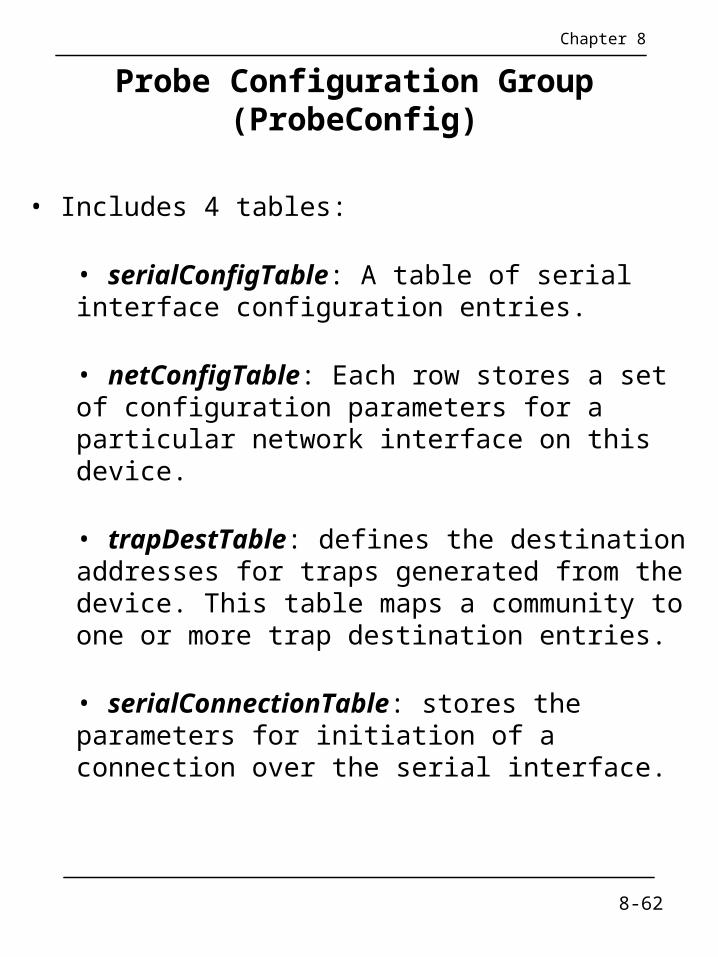
Probe Configuration Group(ProbeConfig)
Chapter 8
• This group controls the configuration of various operating parameters of the probe.
• Enhances interoperability among RMON probes and managers by defining a standard set of configuration parameters for probes → One vendor’s RMON application is able to configure remotely another vendor’s RMON probe.
• Includes a set of scalar objects:• probeCapabilities: indicates which RMON groups are supported on at least one interface by this probe.• probeSoftwareRev: software revision of this device.• probeHardwareRev: hardware revision of this device.• probeDateTime: Probe's current date and time.• probeResetControl: takes on the values running(1), warmBoot(2), and coldBoot(3).• probeDownloadFile: The name of the file that contains the boot image to be downloaded from the TFTP server.• probeDownloadTFTPServer: The IP address of the TFTP server that contains the boot image to load.• probeDownloadAction: takes on the values notDownloading(1), downloadToPROM(2), and downloadToRAM(3).• probeDownloadStatus: The status of the last download procedure, if any. E.g., downloadSuccess(1), … downloadTftpFileNotFound(7), …
8-61
Probe Configuration Group(ProbeConfig)
Chapter 8
• Includes 4 tables:
• serialConfigTable: A table of serial interface configuration entries.
• netConfigTable: Each row stores a set of configuration parameters for a particular network interface on this device.
• trapDestTable: defines the destination addresses for traps generated from the device. This table maps a community to one or more trap destination entries.
• serialConnectionTable: stores the parameters for initiation of a connection over the serial interface.
8-62

Extensions to the RMON 1 MIB for RMON 2 devices
Chapter 8
• These extensions include:
• The standard LastCreateTime Textual Convention for all control tables, and
• An augmentation of the filter entry that provides variable-length offsets into packets.
• Example:
etherStats2Entry OBJECT-TYPESYNTAX
EtherStats2EntryMAX-ACCESS not-accessibleSTATUS currentDESCRIPTION
"Contains the RMON-2 augmentations to RMON-1."
AUGMENTS { etherStatsEntry } ::= { etherStats2Table 1 }
EtherStats2Entry ::= SEQUENCE { etherStatsDroppedFrames
Counter32, etherStatsCreateTime LastCreateTime}
8-63

Notes
ATM RMON
Chapter 8
• ATM Forum extended RMON to ATM.• Switch extensions and ATM RMON define objects at the base layer.• ATM protocol IDs for RMON2 define additional objects at the higher levels.• ATM devices require cell-based measurements and statistics.• Probe should be able to handle high speed.
Upper Layer ProtocolsRMON-2
(RFC 2021, 2074)
EthernetRMON
(RFC 1757)
Token RingRMON
(RFC 1513)
ATM Protocol IDs forRMON-2
(Additions to RFC 2074)
SwitchExtensionsfor RMON
ATMRMON
'Base' Layer
Network Layer
ApplicationLayer
IETF MIBs Additional MIBs
Figure 8.7 RMON MIB Framework (©1995 ATM Forum)
Network Management: Principles and Practice© Mani Subramanian 2000
8-64

Notes
ATM Probe Location
Chapter 8
ATMSwitch
RMONProbe
RMONProbe
ATMSwitch
(a) External Probe with copy (b) Internal Probe with copy
ATM Switchwith internal
RMON Probe
ATMSwitch
ATMSwitch
RMONProbe
(d) External Probe without copy(c) Internal Probe without copy
Figure 8.8 ATM Probe Location ©1995 ATM Forum)
• Stand-alone probe in (a) copies the cells.• Embedded version in (b) reports data, but has no access to switch fabric.• Internal probe (c) similar to (b) with access to switch• Stand-alone probe (d) taps network-to-network interface between two ATM switches.• (a) and (b) require duplex circuits, steering of traffic,
and design modification.• Embedded designs (c) and (d) require no modification.
Network Management: Principles and Practice© Mani Subramanian 2000
8-65

Notes
ATM RMON MIB Groups
Chapter 8
Table 8.6 ATM RMON MIB Groups and Tables
Group OID Function TablesportSelect atmRmonMIBObjects
1Port Selection portSelGrpTable
portSelTableatmStats atmRmonMIBObjects
2Basic Statistics atmStatsControlTable
atmStatsTableatmHost atmRmonMIBObjects
3ATM per-hoststatistics
atmHostControlTableatmHostTable
atmMatrix atmRmonMIBObjects4
ATM per-circuitstatistics
atmMatrixControlTableatmMatrixSDTableatmMatrixDSTableatmMatrixTopNControlTableatmMatrixTopNTable
• ATM RMON MIB contains four groups.• portSelect group selects ports.• atmStats collects basic statistics based on port selection.• atmHost gathers statistics based on host traffic.• atmMatrix group collects conversation traffic and ranks the top-N entries.
Network Management: Principles and Practice© Mani Subramanian 2000
8-66

Notes
A Case StudyChapter 8
• A study at Georgia Tech on Internet traffic growth• Objectives
• Analyze traffic growth and trend• Analyze traffic patterns
• Network comprising Ethernet and FDDI LANs• Tools used to gather data & RMON stats:
• HP Netmetrix protocol analyzer for Ethernet• Special high-speed TCP dump tool for FDDI LAN
• RMON groups utilized• Host top-n• Matrix group• Filter group• Packet capture group (for application level protocols)
Network Management: Principles and Practice© Mani Subramanian 2000
8-67

Case Study Results
Chapter 8
1. Growth Rate: Internet traffic grew at a significant rate from February to June at a monthly rate of 9% to 18%. February to March 12% March to April 9% April to May 18% Note: There is sudden drop in June due to end of spring quarter and summer quarter starting.
2. Traffic Pattern:
- Monthly / Weekly: Only discernible variation is lower traffic over weekends
- Daily: 2/3 of the top 5% peaks occur in the afternoons
- Users: Top six domain of users (96%) are Domain 1 20% Domain 2 30% Subdomain 1 (25%) Subdomain 2 (3%) Domain 3 34% Domain 4 7% Domain 5 3% Domain 6 2%
Top three hosts sending or receiving data Newsgroups Mbone Linux host
What we have learned:
1. The three top groups of users contributing to 84% of the Internet traffic are students (surprise!). Newsgroup services and Domain 1.
2. Growth rate of Internet during the study period in spring quarter is 50%.
Network Management: Principles and Practice© Mani Subramanian 2000
8-68