chapter 8 roof-ceiling constructionecodes.biz/ecodes_support/free_resources...chapter 8 roof-ceiling...
TRANSCRIPT

CHAPTER 8
ROOF-CEILING CONSTRUCTION
SECTION R801GENERAL
R801.1 Application. The provisions of this chapter shall con-trol the design and construction of the roof-ceiling system forall buildings.
R801.2 Requirements. Roof and ceiling construction shall becapable of accommodating all loads imposed according to Sec-tion R301 and of transmitting the resulting loads to the support-ing structural elements.
R801.3 Roof drainage. In areas where expansive or collaps-ible soils are known to exist, all dwellings shall have a con-trolled method of water disposal from roofs that will collectand discharge all roof drainage to the ground surface at least 5feet (1524 mm) from foundation walls or to an approved drain-age system.
SECTION R802WOOD ROOF FRAMING
R802.1 Identification. Load-bearing dimension lumber forrafters, trusses and ceiling joists shall be identified by a grademark of a lumber grading or inspection agency that has beenapproved by an accreditation body that complies with DOC PS20. In lieu of a grade mark, a certificate of inspection issued bya lumber grading or inspection agency meeting the require-ments of this section shall be accepted.
R802.1.1 Blocking. Blocking shall be a minimum of utilitygrade lumber.
R802.1.2 End-jointed lumber. Approved end-jointed lum-ber identified by a grade mark conforming to SectionR802.1 may be used interchangeably with solid-sawn mem-bers of the same species and grade.
R802.1.3 Fire-retardant-treated wood. Fire-retardant-treated wood is any wood product which, when impregnatedwith chemicals by a pressure process or other means duringmanufacture, shall have, when tested in accordance withASTM E84, a listed flame spread index of 25 or less andshow no evidence of significant progressive combustionwhen the test is continued for an additional 20-minute pe-riod. In addition, the flame front shall not progress morethan 10.5 feet (3200 mm) beyond the center line of the burn-ers at any time during the test.
R802.1.3.1 Labeling. Fire-retardant-treated lumber andwood structural panels shall be labeled. The label shallcontain:
1. The identification mark of an approved agency inaccordance with Section 1703.5 of the NorthCarolina Building Code.
2. Identification of the treating manufacturer.
3. The name of the fire-retardant treatment.
4. The species of wood treated.
5. Flame spread and smoke developed rating.
6. Method drying after treatment.
7. Conformance with appropriate standards in accor-dance with Sections R802.1.3.2 throughR802.1.3.5.
8. For FRTW exposed to weather, damp or wet loca-tion, the words “No increase in the listed classifi-cation when subjected to the Standard Rain Test”(ASTM D2898).
R802.1.3.2 Strength adjustments. Design values foruntreated lumber and wood structural panels as specifiedin Section R802.1, shall be adjusted for fire retardant-treated wood. Adjustments to design values shall bebased upon an approved method of investigation whichtakes into consideration the effects of the anticipatedtemperature and humidity to which the fire-retar-dant-treated wood will be subjected, the type of treat-ment and redrying procedures.
R802.1.3.2.1 Wood structural panels. The effect oftreatment and the method of redrying after treatment,and exposure to high temperatures and highhumidities on the flexure properties of fire-retar-dant-treated softwood plywood shall be determinedin accordance with ASTM D 5516. The test data de-veloped by ASTM D 5516 shall be used to developadjustment factors, maximum loads and spans, orboth for untreated plywood design values in accor-dance with ASTM D 6305. Each manufacturer shallpublish the allowable maximum loads and spans forservice as floor and roof sheathing for their treatment.
R802.1.3.2.2 Lumber. For each species of woodtreated the effect of the treatment and the methodofredrying after treatment and exposure to high tem-peratures and high humidities on the allowable designproperties of fire-retardant-treated lumber shall bedetermined in accordance with ASTM D 5664. Thetest data developed by ASTM D 5664 shall be used todevelop modification factors for use at or near roomtemperature and at elevated temperatures and humid-ity in accordance with an approved method of investi-gation. Each manufacturer shall publish themodification factors for service at temperatures of notless than 80°F (26.7°C) and for roof framing. Theroof framing modification factors shall take into con-sideration the climatological location.
R802.1.3.3 Exposure to weather. Where fire-retar-dant-treated wood is exposed to weather, or damp or wetlocations, it shall be identified as “Exterior” to indicatethere is no increase in the listed flamespread index as de-fined in Section R802.1.3 when subjected to ASTM D2898.
2006 NORTH CAROLINA RESIDENTIAL CODE 203

R802.1.3.4 Interior applications. Interior fire-retardant-treated wood shall have a moisture content ofnot over 28 percent when tested in accordance withASTM D 3201 procedures at 92 percent relative humid-ity. Interior fire-retardant-treated wood shall be tested inaccordance with Section R802.1.3.2.1 or R802.1.3.2.2.Interior fire-retardant-treated wood designated as TypeA shall be tested in accordance with the provisions of thissection.
R802.1.3.5 Moisture content. Fire-retardant-treatedwood shall be dried to a moisture content of 19 percent orless for lumber and 15 percent or less for wood structuralpanels before use. For wood kiln dried after treatment(KDAT) the kiln temperatures shall not exceed thoseused in kiln drying the lumber and plywood submittedfor the tests described in Section R802.1.3.2.1 for ply-wood and R802.1.3.2.2 for lumber.
R802.1.4 Structural glued laminated timbers. Gluedlaminated timbers shall be manufactured and identified asrequired in AITC A190.1 and ASTM D3737.
R802.2 Design and construction. Roof-ceilings shall be de-signed and constructed in accordance with the provisions ofthis chapter and Figures R606.10(1), R606.10(2) andR606.10(3) or in accordance with AFPA/NDS. Components ofroof-ceilings shall be fastened in accordance with TableR602.3(1).
R802.3 Framing details. Rafters shall be framed to ridgeboard or to each other with a gusset plate as a tie. Ridge boardshall be at least 1-inch (25.4 mm) nominal thickness and notless in depth than the cut end of the rafter. At all valleys and hipsthere shall be a valley or hip rafter not less than 2-inch (51 mm)nominal thickness and not less in depth than the cut end of therafter. Hip and valley rafters shall be supported at the ridge by abrace to a bearing partition or be designed to carry and distrib-ute the specific load at that point. Where the roof pitch is lessthan three units vertical in 12 units horizontal (25-percentslope), structural members that support rafters and ceilingjoists, such as ridge beams, hips and valleys, shall be designedas beams.
R802.3.1 Ceiling joist and rafter connections. Ceilingjoists and rafters shall be nailed to each other in accordancewith Tables R602.3(1) and R802.5.1(9), and the assemblyshall be nailed to the top wall plate in accordance with TableR602.3(1). Ceiling joists shall be continuous or securelyjoined where they meet over interior partitions and nailed toadjacent rafters to provide a continuous tie across the build-ing when such joists are parallel to the rafters.
Where ceiling joists are not parallel to rafters,subflooring or metal straps attached to the ends of the raftersshall be installed in a manner to provide a continuous tieacross the building, or rafters shall be tied to 1-inch by4-inch (25.4 mm by 102 mm) (nominal) minimum-sizecrossties. The connections shall be in accordance with TableR602.3(1) or connections of equivalent capacities shall beprovided. Where ceiling joists or rafter ties are not providedat the top plate, the ridge formed by these rafters shall alsobe supported by a girder designed in accordance with ac-cepted engineering practice.
Rafter ties shall be spaced not more than 4 feet (1219 mm)on center.
A 1-inch by 6-inch (25 mm × 152 mm) or 2-inch by4-inch (51 mm × 102 mm) collar beam shall be nailed in theupper third of the roof to every third pair of rafters not to ex-ceed 4 feet on center. Collar beams shall be connected to therafters as specified in Table R602.3(1) for rafter ties.
R802.3.2 Ceiling joists lapped. Ends of ceiling joists shallbe lapped a minimum of 3 inches (76 mm) or butted overbearing partitions or beams and toenailed to the bearingmember. When ceiling joists are used to provide resistanceto rafter thrust, lapped joists shall be nailed together in ac-cordance with Table R602.3(1) and butted joists shall betied together in a manner to resist such thrust.
R802.4 Allowable ceiling joist spans. Spans for ceiling joistsshall be in accordance with Tables R802.4(1) and R802.4(2).For other grades and species and for other loading conditions,refer to the AF&PA Span Tables for Joists and Rafters.
R802.5 Allowable rafter spans. Spans for rafters shall be inaccordance with Tables R802.5.1(1) through R802.5.1(8). Forother grades and species and for other loading conditions, referto the AF&PA Span Tables for Joists and Rafters. The span ofeach rafter shall be measured along the horizontal projection ofthe rafter.
R802.5.1 Purlins. Purlins are permitted to be installed to re-duce the span of rafters as shown in Figure R802.5.1. Pur-lins shall be sized no less than the required size of the raftersthat they support. Purlins shall be continuous and shall besupported by 2-inch by 4-inch (51 mm by 102 mm) bracesinstalled to bearing walls at a slope not less than 45 degreesfrom the horizontal. The braces shall be spaced not morethan 4 feet (1219 mm) on center and the unbraced length ofbraces shall not exceed 8 feet (2438 mm).
R802.6 Bearing. The ends of each rafter or ceiling joist shallhave not less than 11/2 inches (38 mm) of bearing on wood ormetal and not less than 3 inches (76 mm) on masonry or con-crete.
R802.6.1 Finished ceiling material. If the finished ceilingmaterial is installed on the ceiling prior to the attachment ofthe ceiling to the walls, such as in construction at a factory, acompression strip of the same thickness as the finish ceilingmaterial shall be installed directly above the top plate ofbearing walls if the compressive strength of the finish ceil-ing material is less than the loads it will be required to with-stand. The compression strip shall cover the entire length ofsuch top plate and shall be at least one-half the width of thetop plate. It shall be of material capable of transmitting theloads transferred through it.
R802.7 Cutting and notching. Structural roof members shallnot be cut, bored or notched in excess of the limitations speci-fied in this section.
R802.7.1 Sawn lumber. Notches in solid lumber joists, raf-ters and beams shall not exceed one-sixth of the depth of themember, shall not be longer than one-third of the depth ofthe member and shall not be located in the middle one-thirdof the span. Notches at the ends of the member shall not ex-ceed one-fourth the depth of the member. The tension side
204 2006 NORTH CAROLINA RESIDENTIAL CODE
ROOF-CEILING CONSTRUCTION

of members 4 inches (102 mm) or greater in nominal thick-ness shall not be notched except at the ends of the members.The diameter of the holes bored or cut into members shallnot exceed one-third the depth of the member. Holes shallnot be closer than 2 inches (51 mm) to the top or bottom ofthe member, or to any other hole located in the member.Where the member is also notched, the hole shall not becloser than 2 inches (51 mm) to the notch.
Exception: Notches on cantilevered portions of raftersare permitted provided the dimension of the remainingportion of the rafter is not less than 4-inch nominal (102mm) and the length of the cantilever does not exceed 24inches (610 mm).
R802.7.2 Engineered wood products. Cuts, notches andholes bored in laminated veneer lumber, glue-laminatedmembers or I-joists are not permitted unless the effect ofsuch penetrations are specifically considered in the designof the member.
R802.8 Lateral support. Rafters and ceiling joists having adepth-to-thickness ratio exceeding 5 to 1 based on nominal di-mensions shall be provided with lateral support at points ofbearing to prevent rotation.
R802.8.1 Bridging. Rafters and ceiling joists having adepth-to-thickness ratio exceeding 6 to 1 based on nominaldimensions shall be supported laterally by solid blocking,diagonal bridging (wood or metal) or a continuous 1-inch by3-inch (25.4 mm by 76 mm) wood strip nailed across the raf-ters or ceiling joists at intervals not exceeding 8 feet (2438mm).
R802.9 Framing of openings. Openings in roof and ceilingframing shall be framed with header and trimmer joists. Whenthe header joist span does not exceed 4 feet (1219 mm), theheader joist may be a single member the same size as the ceilingjoist or rafter. Single trimmer joists may be used to carry a sin-gle header joist that is located within 3 feet (914 mm) of thetrimmer joist bearing. When the header joist span exceeds 4feet (1219 mm), the trimmer joists and the header joist shall bedoubled and of sufficient cross section to support the ceilingjoists or rafter framing into the header. Approved hangers shallbe used for the header joist to trimmer joist connections whenthe header joist span exceeds 6 feet (1829 mm). Tail joists over12 feet (3658 mm) long shall be supported at the header byframing anchors or on ledger strips not less than 2 inches by 2inches (51 mm by 51 mm).
R802.10 Wood trusses.
R802.10.1 Truss design drawings. Truss design drawings,prepared in conformance with Section R802.10.1, shall beprovided to the building official and approved prior to in-stallation. Truss design drawings shall include, at a mini-mum, the information specified below. Truss designdrawing shall be provided with the shipment of trusses de-livered to the jobsite.
1. Slope or depth, span and spacing.
2. Location of all joints.
3. Required bearing widths.
4. Design loads as applicable.
4.1. Top chord live load (including snow loads).
4.2. Top chord dead load.
4.3. Bottom chord live load.
4.4. Bottom chord dead load.
4.5. Concentrated loads and their points of appli-cation.
4.6. Controlling wind and earthquake loads.
5. Adjustments to lumber and joint connector designvalues for conditions of use.
6. Each reaction force and direction.
7. Joint connector type and description (e.g., size,thickness or gauge) and the dimensioned location ofeach joint connector except where symmetricallylocated relative to the joint interface.
8. Lumber size, species and grade for each member.
9. Connection requirements for:
9.1. Truss to truss girder.
9.2. Truss ply to ply.
9.3. Field splices.
10. Calculated deflection ratio and/or maximum de-scription for live and total load.
11. Maximum axial compression forces in the trussmembers to enable the building designer to designthe size, connections and anchorage of the perma-nent continuous lateral bracing. Forces shall beshown on the truss design drawing or on supplemen-tal documents.
12. Required permanent truss member bracinglocation.
R802.10.2 Design. Wood trusses shall be designed in accor-dance with accepted engineering practice. The design andmanufacture of metal plate connected wood trusses shallcomply with ANSI/TPI 1. The truss design drawings shallbe prepared by a registered professional where required bythe statutes of the jurisdiction in which the project is to beconstructed in accordance with Section R106.1.
R802.10.3 Bracing. Trusses shall be braced to prevent rota-tion and provide lateral stability in accordance with the re-quirements specified in the construction documents for thebuilding and on the individual truss design drawings. In theabsence of specific bracing requirements, trusses shall bebraced in accordance with TPI/HIB.
R802.10.4 Alterations to trusses. Truss members shall notbe cut, notched, drilled, spliced or otherwise altered in anyway without the approval of a registered design professional.Alterations resulting in the addition of load (e.g., HVACequipment, water heater) that exceeds the design load for the
2006 NORTH CAROLINA RESIDENTIAL CODE 205
ROOF-CEILING CONSTRUCTION

206 2006 NORTH CAROLINA RESIDENTIAL CODE
ROOF-CEILING CONSTRUCTION
TABLE R802.4(1)CEILING JOIST SPANS FOR COMMON LUMBER SPECIES
(Uninhabitable attics without storage, live load = 10 psf, L/Δ = 240)
CEILING JOISTSPACING(inches) SPECIES AND GRADE
DEAD LOAD = 5 psf
2 × 4 2 × 6 2 × 8 2 × 10
Maximum ceiling joist spans
(feet - inches) (feet - inches) (feet - inches) (feet - inches)
12
Douglas fir-larch SSDouglas fir-larch #1Douglas fir-larch #2Douglas fir-larch #3Hem-fir SSHem-fir #1Hem-fir #2Hem-fir #3Southern pine SSSouthern pine #1Southern pine #2Southern pine #3Spruce-pine-fir SSSpruce-pine-fir #1Spruce-pine-fir #2Spruce-pine-fir #3
13-212-812-510-1012-512-211-710-1012-1112-812-511-612-211-1011-1010-10
20-819-1119-615-1019-619-118-215-1020-319-1119-617-019-118-818-815-10
Note aNote a25-820-125-825-224-020-1
Note aNote a25-821-825-224-724-720-1
Note aNote aNote a24-6
Note aNote aNote a24-6
Note aNote aNote a25-7
Note aNote aNote a24-6
16
Douglas fir-larch SSDouglas fir-larch #1Douglas fir-larch #2Douglas fir-larch #3Hem-fir SSHem-fir #1Hem-fir #2Hem-fir #3Southern pine SSSouthern pine #1Southern pine #2Southern pine #3Spruce-pine-fir SSSpruce-pine-fir #1Spruce-pine-fir #2Spruce-pine-fir #3
11-1111-611-39-511-311-010-69-511-911-611-310-011-010-910-99-5
18-918-117-813-917-817-416-613-918-518-117-814-917-416-1116-1113-9
24-823-1023-017-523-422-1021-917-524-323-123-418-922-1022-422-417-5
Note aNote aNote a21-3
Note aNote aNote a21-3
Note aNote aNote a22-2
Note aNote aNote a21-3
19.2
Douglas fir-larch SSDouglas fir-larch #1Douglas fir-larch #2Douglas fir-larch #3Hem-fir SSHem-fir #1Hem-fir #2Hem-fir #3Southern -pine SSSouthern pine #1Southern pine #2Southern pine #3Spruce-pine-fir SSSpruce-pine-fir #1Spruce-pine-fir #2Spruce-pine-fir #3
11-310-1010-78-710-710-49-118-711-010-1010-79-110-410-210-28-7
17-817-016-712-616-816-415-712-617-417-016-813-616-415-1115-1112-6
23-322-521-015-1021-1121-620-615-1022-1022-521-1117-221-621-021-015-10
Note aNote a25-819-5
Note aNote a25-319-5
Note aNote aNote a20-3
Note a25-825-819-5
(continued)

2006 NORTH CAROLINA RESIDENTIAL CODE 207
ROOF-CEILING CONSTRUCTION
TABLE R802.4(1)—continuedCEILING JOIST SPANS FOR COMMON LUMBER SPECIES
(Uninhabitable attics without storage, live load = 10 psf, L/Δ = 240)
CEILING JOISTSPACING(inches) SPECIES AND GRADE
DEAD LOAD = 5 psf
2 × 4 2 × 6 2 × 8 2 × 10
Maximum ceiling joist spans
(feet - inches) (feet - inches) (feet - inches) (feet - inches)
24
Douglas fir-larch SSDouglas fir-larch #1Douglas fir-larch #2Douglas fir-larch #3Hem-fir SSHem-fir #1Hem-fir #2Hem-fir #3Southern pine SSSouthern pine #1Southern pine #2Southern pine #3Spruce-pine-fir SSSpruce-pine-fir #1Spruce-pine-fir #2Spruce-pine-fir #3
10-510-09-107-89-109-89-27-810-310-09-108-29-89-59-57-8
16-415-914-1011-215-615-214-511-216-115-915-612-015-214-914-911-2
21-720-118-914-220-519-718-614-221-220-1020-115-419-1118-918-914-2
Note a24-6
22-1117-4
Note a23-1122-717-4
Note aNote a23-1118-125-5
22-1122-1117-4
Check sources for availability of lumber in lengths greater than 20 feet.For SI: 1 inch = 25.4 mm, 1 foot = 304.8 mm, 1 pound per square foot = 0.0479kN/m2.a. Span exceeds 26 feet in length.

208 2006 NORTH CAROLINA RESIDENTIAL CODE
ROOF-CEILING CONSTRUCTION
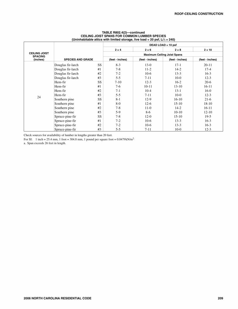
TABLE R802.4(2)CEILING JOIST SPANS FOR COMMON LUMBER SPECIES
(Uninhabitable attics with limited storage, live load = 20 psf, L/Δ = 240)
CEILING JOISTSPACING(inches) SPECIES AND GRADE
DEAD LOAD = 10 psf
2 × 4 2 × 6 2 × 8 2 × 10
Maximum ceiling joist spans
(feet - inches) (feet - inches) (feet - inches) (feet - inches)
12
Douglas fir-larch SSDouglas fir-larch #1Douglas fir-larch #2Douglas fir-larch #3Hem-fir SSHem-fir #1Hem-fir #2Hem-fir #3Southern pine SSSouthern pine #1Southern pine #2Southern pine #3Spruce-pine-fir SSSpruce-pine-fir #1Spruce-pine-fir #2Spruce-pine-fir #3
10-510-09-107-89-109-89-27-810-310-09-108-29-89-59-57-8
16-415-914-1011-215-615-214-511-216-115-915-612-015-214-914-911-2
21-720-118-914-220-519-718-614-221-220-1020-115-419-1118-918-914-2
Note a24-6
22-1117-4
Note a23-1122-717-4
Note aNote a23-1118-125-5
22-1122-1117-4
16
Douglas fir-larch SSDouglas fir-larch #1Douglas fir-larch #2Douglas fir-larch #3Hem-fir SSHem-fir #1Hem-fir #2Hem-fir #3Southern pine SSSouthern pine #1Southern pine #2Southern pine #3Spruce-pine-fir SSSpruce-pine-fir #1Spruce-pine-fir #2Spruce-pine-fir #3
9-69-18-96-88-118-98-46-89-49-18-117-18-98-78-76-8
14-1113-912-109-814-113-512-89-814-714-413-610-513-912-1012-109-8
19-717-516-312-418-616-1016-012-419-318-1117-513-318-116-316-312-4
25-021-3
19-1015-023-820-819-715-024-723-120-915-823-1
19-1019-1015-0
19.2
Douglas fir-larch SSDouglas fir-larch #1Douglas fir-larch #2Douglas fir-larch #3Hem-fir SSHem-fir #1Hem-fir #2Hem-fir #3Southern pine SSSouthern pine #1Southern pine #2Southern pine #3Spruce-pine-fir SSSpruce-pine-fir #1Spruce-pine-fir #2Spruce-pine-fir #3
8-118-78-06-18-58-37-106-18-98-78-56-58-38-08-06-1
14-012-611-98-1013-312-311-78-1013-913-612-39-6
12-1111-911-98-10
18-515-1014-1011-317-515-614-811-318-117-915-1012-117-114-1014-1011-3
23-419-518-213-822-3
18-1117-1013-823-121-1
18-1114-421-818-218-213-8
(continued)
2006 NORTH CAROLINA RESIDENTIAL CODE 209
ROOF-CEILING CONSTRUCTION
TABLE R802.4(2)—continuedCEILING JOIST SPANS FOR COMMON LUMBER SPECIES
(Uninhabitable attics with limited storage, live load = 20 psf, L/Δ = 240)
CEILING JOISTSPACING(inches) SPECIES AND GRADE
DEAD LOAD = 10 psf
2 × 4 2 × 6 2 × 8 2 × 10
Maximum Ceiling Joist Spans
(feet - inches) (feet - inches) (feet - inches) (feet - inches)
24
Douglas fir-larch SSDouglas fir-larch #1Douglas fir-larch #2Douglas fir-larch #3Hem-fir SSHem-fir #1Hem-fir #2Hem-fir #3Southern pine SSSouthern pine #1Southern pine #2Southern pine #3Spruce-pine-fir SSSpruce-pine-fir #1Spruce-pine-fir #2Spruce-pine-fir #3
8-37-87-25-57-107-67-15-58-18-07-85-97-87-27-25-5
13-011-210-67-1112-310-1110-47-1112-912-611-08-612-010-610-67-11
17-114-213-310-016-213-1013-110-016-1015-1014-210-1015-1013-313-310-0
20-1117-416-312-320-6
16-1116-012-321-6
18-1016-1112-1019-516-316-312-3
Check sources for availability of lumber in lengths greater than 20 feet.For SI: 1 inch = 25.4 mm, 1 foot = 304.8 mm, 1 pound per square foot = 0.0479kN/m2.
a. Span exceeds 26 feet in length.

210 2006 NORTH CAROLINA RESIDENTIAL CODE
ROOF-CEILING CONSTRUCTION
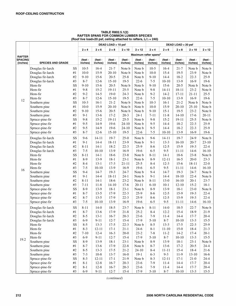
TABLE R802.5.1(1)RAFTER SPANS FOR COMMON LUMBER SPECIES
(Roof live load=20 psf, ceiling not attached to rafters, L/Δ = 180)
RAFTERSPACING(inches) SPECIES AND GRADE
DEAD LOAD = 10 psf DEAD LOAD = 20 psf
2 × 4 2 × 6 2 × 8 2 × 10 2 × 12 2 × 4 2 × 6 2 × 8 2 × 10 2 × 12
Maximum rafter spansa
(feet -inches)
(feet -inches)
(feet -inches)
(feet -inches)
(feet -inches)
(feet -inches)
(feet -inches)
(feet -inches)
(feet -inches)
(feet -inches)
12
Douglas fir-larch SSDouglas fir-larch #1Douglas fir-larch #2Douglas fir-larch #3Hem-fir SSHem-fir #1Hem-fir #2Hem-fir #3Southern pine SSSouthern pine #1Southern pine #2Southern pine #3Spruce-pine-fir SSSpruce-pine-fir #1Spruce-pine-fir #2Spruce-pine-fir #3
11-61-11-108-7
10-1010 -710-18-711-311-110-109-110-710-410-48-7
18-017-416-712-617-016-815-1112-617-817-417-013-616-816-316-312-6
23-922-521-015-1022-521-1020-815-1023-422-1122-517-221-1121-021-015-10
Note bNote b25-819-5
Note bNote b25-319-5
Note bNote bNote b20-3
Note b25-825-819-5
Note bNote bNote b22-6
Note bNote bNote b22-6
Note bNote bNote b24-1
Note bNote bNote b22-6
11-610-69-107-5
10-1010-39-87-511-311-110-67-1110-79-109-107-5
18-015-414-410-1017-014-1114-210-1017-817-315-111-816-814-414-410-10
23-519-518-213-922-518-1117-1113-923-421-919-514-1021-918-218-213-9
Note b23-922-316-9
Note b23-2
21-1116-9
Note b25-1023-217-6
Note b22-322-316-9
Note bNote b25-919-6
Note bNote b25-519-6
Note bNote bNote b20-11Note b25-925-919-6
16
Douglas fir-larch SSDouglas fir-larch #1Douglas fir-larch #2Douglas fir-larch #3Hem-fir SSHem-fir #1Hem-fir #2Hem-fir #3Southern pine SSSouthern pine #1Southern pine #2Southern pine #3Spruce-pine-fir SSSpruce-pine-fir #1Spruce-pine-fir #2Spruce-pine-fir #3
10-510-09-107-59-109-89-27-510-310-09-107-119-89-59-57-5
16-415-414-410-1015-614-1114-210-1016-115-915-111-815-214-414-410-10
21-719-518-213-920-518-1117-1113-921-220-1019-514-1019-1118-218-213-9
Note b23-922-316-9
Note b23-221-1116-9
Note b25-1023-217-625-522-322-316-9
Note bNote b25-919-6
Note bNote b25-519-6
Note bNote bNote b20-11Note b25-925-919-6
10-59-18-66-59-108-108-56-510-310-09-16-109-88-68-66-5
16-013-312-59-515-612-1112-39-516-115-013-010-114-1012-512-59-5
20-316-1015-911-1119-1116-515-611-1121-218-1016-1012-1018-1015-915-911-11
24-920-719-314-624-420-0
18-1114-6
Note b22-420-115-223-019-319-314-6
Note b23-1022-4
16-10Note b23-322-0
16-10Note bNote b23-718-1
Note b22-422-4
16-10
19.2
Douglas fir-larch SSDouglas fir-larch #1Douglas fir-larch #2Douglas fir-larch #3Hem-fir SSHem-fir #1Hem-fir #2Hem-fir #3Southern pine SSSouthern pine #1Southern pine #2Southern pine #3Spruce-pine-fir SSSpruce-pine-fir #1Spruce-pine-fir #2Spruce-pine-fir #3
9-109-58-116-99-39-18-86-99-89-59-37-39-18-108-106-9
15-514-013-19-1114-713-812-119-1115-214-1013-910-814-313-113-19-11
20-417-916-712-719-217-416-412-719-1119-717-913-718-916-716-712-7
25-1121-820-315-424-621-120-015-425-523-721-216-023-1120-320-315-4
Note b25-223-617-9
Note b24-623-217-9
Note bNote b24-1019-1
Note b23-623-617-9
9-108-47-95-109-38-17-85-109-89-38-46-39-17-97-95-10
14-712-211-48-714-411-1011-28-715-213-811-119-313-711-411-48-7
18-615-414-410-1018-215-014-210-1019-1117-215-411-917-214-414-410-10
22-718-917-713-322-318-417-413-325-520-518-4
13-1021-017-717-713-3
Note b21-920-415-525-921-320-115-5
Note b24-421-616-624-420-420-415-5
(continued)

2006 NORTH CAROLINA RESIDENTIAL CODE 211
ROOF-CEILING CONSTRUCTION
TABLE R802.5.1(1)—continuedRAFTER SPANS FOR COMMON LUMBER SPECIES
(Roof live load=20 psf, ceiling not attached to rafters, L/Δ = 180)
RAFTERSPACING(inches) SPECIES AND GRADE
DEAD LOAD = 10 psf DEAD LOAD = 20 psf
2 × 4 2 × 6 2 × 8 2 × 10 2 × 12 2 × 4 2 × 6 2 × 8 2 × 10 2 × 12
Maximum rafter spansa
(feet -inches)
(feet -inches)
(feet -inches)
(feet -inches)
(feet -inches)
(feet -inches)
(feet -inches)
(feet -inches)
(feet -inches)
(feet -inches)
24
Douglas fir-larch SSDouglas fir-larch #1Douglas fir-larch #2Douglas fir-larch #3Hem-fir SSHem-fir #1Hem-fir #2Hem-fir #3Southern pine SSSouthern pine #1Southern pine #2Southern pine #3Spruce-pine-fir SSSpruce-pine-fir #1Spruce-pine-fir #2Spruce-pine-fir #3
9-18-78-06-18-78-47-116-18-118-98-76-58-58-08-06-1
14-412-611-98-1013-612-311-78-1014-113-912-39-613-311-911-98-10
18-1015-1014-1011-317-1015-614-811-318-617-915-1012-117-514-1014-1011-3
23-419-518-213-822-918-1117-1013-823-821-118-1114-421-818-218-213-8
Note b22-621-015-11Note b21-1120-915-11Note b25-222-217-125-221-021-015-11
8-117-56-115-38-77-36-105-38-118-37-55-78-46-116-115-3
13-110-1010-27-8
12-1010-710-07-814-112-310-88-312-210-210-27-8
16-713-912-109-916-313-512-89-918-615-413-910-615-412-1012-109-9
20-316-915-8
11-1019-1016-415-6
11-1022-1118-316-512-518-915-815-8
11-10
23-519-618-313-923-019-0
17-1113-9
Note b21-919-314-921-918-318-313-9
Check sources for availability of lumber in lengths greater than 20 feet.For SI: 1 inch = 25.4 mm, 1 foot = 304.8 mm, 1 pound per square foot = 0.0479kN/m2.a. The tabulated rafter spans assume that ceiling joists are located at the bottom of the attic space or that some other method of resisting the outward push of the rafters
on the bearing walls, such as rafter ties, is provided at that location. When ceiling joists or rafter ties are located higher in the attic space, the rafter spans shall bemultiplied by the factors given below:
HC/HR Rafter Span Adjustment Factor
2/3 or greater 0.50
1/2 0.58
1/3 0.67
1/4 0.76
1/5 0.83
1/6 0.90
1/7.5 and less 1.00
where: HC = Height of ceiling joists or rafter ties measured vertically above the top of the rafter support walls.
HR = Height of roof ridge measured vertically above the top of the rafter support walls.b. Span exceeds 26 feet in length.
212 2006 NORTH CAROLINA RESIDENTIAL CODE
ROOF-CEILING CONSTRUCTION
TABLE R802.5.1(2)RAFTER SPANS FOR COMMON LUMBER SPECIES
(Roof live load=20 psf, ceiling attached to rafters, L/Δ = 240)
RAFTERSPACING(inches) SPECIES AND GRADE
DEAD LOAD = 10 psf DEAD LOAD = 20 psf
2 × 4 2 × 6 2 × 8 2 × 10 2 × 12 2 × 4 2 × 6 2 × 8 2 × 10 2 × 12
Maximum rafter spansa
(feet -inches)
(feet -inches)
(feet -inches)
(feet -inches)
(feet -inches)
(feet -inches)
(feet -inches)
(feet -inches)
(feet -inches)
(feet -inches)
12
Douglas fir-larch SSDouglas fir-larch #1Douglas fir-larch #2Douglas fir-larch #3Hem-fir SSHem-fir #1Hem-fir #2Hem-fir #3Southern pine SSSouthern pine #1Southern pine #2Southern pine #3Spruce-pine-fir SSSpruce-pine-fir #1Spruce-pine-fir #2Spruce-pine-fir #3
10-510-09-108-79-109-89-28-710-310-09-109-19-89-59-58-7
16-415-915-612-615-615-214-512-616-115-915-613-615-214-914-912-6
21-720-1020-515-1020-519-1119-015-1021-220-1020-517-219-1119-619-615-10
Note bNote b25-819-5
Note b25-524-319-5
Note bNote bNote b20-325-524-1024-1019-5
Note bNote bNote b22-6
Note bNote bNote b22-6
Note bNote bNote b24-1
Note bNote bNote b22-6
10-510-09-107-59-109-89-27-510-310-09-107-119-89-59-57-5
16-415-414-410-1015-614-1114-210-1016-115-915-111-815-214-414-410-10
21-719-518-213-920-518-1117-1113-921-220-1019-514-1019-1118-218-213-9
Note b23-922-316-9
Note b23-2
21-1116-9
Note b25-1023-217-625-522-322-316-9
Note bNote b25-919-6
Note bNote b25-519-6
Note bNote bNote b20-11Note b25-925-919-6
16
Douglas fir-larch SSDouglas fir-larch #1Douglas fir-larch #2Douglas fir-larch #3Hem-fir SSHem-fir #1Hem-fir #2Hem-fir #3Southern pine SSSouthern pine #1Southern pine #2Southern pine #3Spruce-pine-fir SSSpruce-pine-fir #1Spruce-pine-fir #2Spruce-pine-fir #3
9-69-18-117-58-118-98-47-59-49-18-117-118-98-78-77-5
14-1114-414-110-1014-113-913-110-1014-714-414-111-813-913-513-510-10
19-718-1118-213-918-618-117-313-919-318-1118-614-1018-117-917-913-9
25-023-922-316-923-823-121-1116-924-724-123-217-623-122-322-316-9
Note bNote b25-919-6
Note bNote b25-519-6
Note bNote bNote b20-11Note b25-925-919-6
9-69-18-66-58-118-98-46-59-49-18-116-108-98-68-66-5
14-1113-312-59-514-112-1112-39-514-714-413-010-113-912-512-59-5
19-716-1015-911-1118-616-515-611-1119-318-1016-1012-1018-115-915-911-11
24-920-719-314-623-820-0
18-1114-624-722-420-115-223-019-319-314-6
Note b23-1022-4
16-10Note b23-322-0
16-10Note bNote b23-718-1
Note b22-422-4
16-10
19.2
Douglas fir-larch SSDouglas fir-larch #1Douglas fir-larch #2Douglas fir-larch #3Hem-fir SSHem-fir #1Hem-fir #2Hem-fir #3Southern pine SSSouthern pine #1Southern pine #2Southern pine #3Spruce-pine-fir SSSpruce-pine-fir #1Spruce-pine-fir #2Spruce-pine-fir #3
8-118-78-56-98-58-37-106-98-98-78-57-38-38-18-16-9
14-013-613-19-1113-312-1112-49-1113-913-613-310-812-1112-812-89-11
18-517-916-712-717-517-116-312-718-117-917-513-717-116-716-712-7
23-721-820-315-422-321-120-015-423-122-821-216-021-920-320-315-4
Note b25-223-617-9
Note b24-623-217-9
Note bNote b24-1019-1
Note b23-623-617-9
8-118-47-95-108-58-17-85-108-98-78-46-38-37-97-95-10
14-012-211-48-713-311-1011-28-713-913-611-119-3
12-1111-411-48-7
18-515-414-410-1017-515-014-210-1018-117-215-411-917-114-414-410-10
22-718-917-713-322-318-417-413-323-120-518-4
13-1021-017-717-713-3
Note b21-920-415-525-921-320-115-5
Note b24-421-616-624-420-420-415-5
(continued)

2006 NORTH CAROLINA RESIDENTIAL CODE 213
ROOF-CEILING CONSTRUCTION
TABLE R802.5.1(2)—continuedRAFTER SPANS FOR COMMON LUMBER SPECIES
(Roof live load=20 psf, ceiling attached to rafters, L/Δ = 240)
RAFTERSPACING(inches) SPECIES AND GRADE
DEAD LOAD = 10 psf DEAD LOAD = 20 psf
2 × 4 2 × 6 2 × 8 2 × 10 2 × 12 2 × 4 2 × 6 2 × 8 2 × 10 2 × 12
Maximum rafter spansa
(feet -inches)
(feet -inches)
(feet -inches)
(feet -inches)
(feet -inches)
(feet -inches)
(feet -inches)
(feet -inches)
(feet -inches)
(feet -inches)
24
Douglas fir-larch SSDouglas fir-larch #1Douglas fir-larch #2Douglas fir-larch #3Hem-fir SSHem-fir #1Hem-fir #2Hem-fir #3Southern pine SSSouthern pine #1Southern pine #2Southern pine #3Spruce-pine-fir SSSpruce-pine-fir #1Spruce-pine-fir #2Spruce-pine-fir #3
8-38-07-106-17-107-87-36-18-18-07-106-57-87-67-66-1
13-012-611-98-1012-312-011-58-1012-912-612-39-612-011-911-98-10
17-215-1014-1011-316-215-614-811-316-1016-615-1012-115-1014-1014-1011-3
21-1019-518-213-820-818-1117-1013-821-621-118-1114-420-218-218-213-8
Note b22-621-015-1125-121-1120-915-11Note b25-222-217-124-721-021-015-11
8-37-56-115-37-107-36-105-38-18-07-55-77-86-116-115-3
13-010-1010-27-812-310-710-07-812-912-310-88-312-010-210-27-8
16-713-912-109-916-213-512-89-9
16-1015-413-910-615-412-1012-109-9
20-316-915-8
11-1019-1016-415-6
11-1021-618-316-512-518-915-815-8
11-10
23-519-618-313-923-019-0
17-1113-9
Note b21-919-314-921-918-318-313-9
Check sources for availability of lumber in lengths greater than 20 feet.For SI: 1 inch = 25.4 mm, 1 foot = 304.8 mm, 1 pound per square foot = 0.0479kN/m2.a. The tabulated rafter spans assume that ceiling joists are located at the bottom of the attic space or that some other method of resisting the outward push of the rafters
on the bearing walls, such as rafter ties, is provided at that location. When ceiling joists or rafter ties are located higher in the attic space, the rafter spans shall bemultiplied by the factors given below:
HC/HR Rafter Span Adjustment Factor
2/3 or greater 0.50
1/2 0.58
1/3 0.67
1/4 0.76
1/5 0.83
1/6 0.90
1/7.5 and less 1.00
where: HC = Height of ceiling joists or rafter ties measured vertically above the top of the rafter support walls.
HR = Height of roof ridge measured vertically above the top of the rafter support walls.b. Span exceeds 26 feet in length.

214 2006 NORTH CAROLINA RESIDENTIAL CODE
ROOF-CEILING CONSTRUCTION
TABLE R802.5.1(3)RAFTER SPANS FOR COMMON LUMBER SPECIES
(Ground snow load=30 psf, ceiling not attached to rafters, L/Δ = 180)
RAFTERSPACING(inches) SPECIES AND GRADE
DEAD LOAD = 10 psf DEAD LOAD = 20 psf
2 × 4 2 × 6 2 × 8 2 × 10 2 × 12 2 × 4 2 × 6 2 × 8 2 × 10 2 × 12
Maximum rafter spansa
(feet -inches)
(feet -inches)
(feet -inches)
(feet -inches)
(feet -inches)
(feet -inches)
(feet -inches)
(feet -inches)
(feet -inches)
(feet -inches)
12
Douglas fir-larch SSDouglas fir-larch #1Douglas fir-larch #2Douglas fir-larch #3Hem-fir SSHem-fir #1Hem-fir #2Hem-fir #3Southern pine SSSouthern pine #1Southern pine #2Southern pine #3Spruce-pine-fir SSSpruce-pine-fir #1Spruce-pine-fir #2Spruce-pine-fir #3
10-09-89-57-19-69-38-107-19-109-89-67-79-39-19-17-1
15-914-913-910-514-1014-413-710-515-615-214-511-214-713-913-910-5
20-918-817-513-219-718-217-213-220-520-018-814-319-217-517-513-2
Note b22-921-416-125-022-221-016-1
Note b24-922-316-1024-621-421-416-1
Note bNote b24-818-8
Note b25-924-418-8
Note bNote bNote b20-0
Note b24-824-818-8
10-09-08-56-49-68-98-46-49-109-89-06-99-38-58-56-4
15-913-212-49-4
14-1012-1012-29-415-614-1012-1110-014-712-412-49-4
20-116-815-711-919-716-315-411-920-518-816-812-918-815-715-711-9
24-620-419-114-524-1
19-1018-914-5
Note b22-2
19-1115-122-919-119-114-5
Note b23-722-116-8
Note b23-021-916-8
Note bNote b23-4
17-11Note b22-122-116-8
16
Douglas fir-larch SSDouglas fir-larch #1Douglas fir-larch #2Douglas fir-larch #3Hem-fir SSHem-fir #1Hem-fir #2Hem-fir #3Southern pine SSSouthern pine #1Southern pine #2Southern pine #3Spruce-pine-fir SSSpruce-pine-fir #1Spruce-pine-fir #2Spruce-pine-fir #3
9-18-98-26-28-78-58-06-28-118-98-76-78-58-28-26-2
14-412-911-119-013-612-511-99-014-113-912-69-813-311-1111-119-0
18-1016-215-111-517-1015-914-1111-518-618-116-212-417-515-115-111-5
23-919-918-513-1122-919-318-213-1123-821-519-314-722-118-518-513-11
Note b22-1021-516-2
Note b22-321-116-2
Note b25-722-717-425-721-521-516-2
9-17-107-35-68-77-77-25-68-118-87-105-108-57-37-35-6
13-911-510-88-113-611-110-68-114-112-1011-28-812-910-810-88-1
17-514-513-610-317-114-113-410-318-616-214-511-016-213-613-610-3
21-317-816-612-6
20-1017-216-312-623-819-217-313-019-916-616-612-6
24-820-519-214-624-2
19-1118-1014-6
Note b22-1020-215-6
22-1019-219-214-6
19.2
Douglas fir-larch SSDouglas fir-larch #1Douglas fir-larch #2Douglas fir-larch #3Hem-fir SSHem-fir #1Hem-fir #2Hem-fir #3Southern pine SSSouthern pine #1Southern pine #2Southern pine #3Spruce-pine-fir SSSpruce-pine-fir #1Spruce-pine-fir #2Spruce-pine-fir #3
8-77-117-55-78-17-97-45-78-58-37-116-07-117-57-55-7
13-611-810-118-312-911-410-98-313-313-011-58-1012-510-1110-118-3
17-914-913-910-516-914-413-710-517-516-614-911-316-513-913-910-5
21-818-016-1012-921-417-716-712-922-319-717-713-420-216-1016-1012-9
25-220-1119-614-924-820-419-314-9
Note b23-420-715-1023-419-619-614-9
8-77-16-85-08-16-116-75-08-57-117-15-47-116-86-85-0
12-610-59-97-412-410-29-77-413-311-910-27-1111-89-99-97-4
15-1013-212-49-415-712-1012-29-417-514-913-210-114-912-412-49-4
19-516-115-111-519-115-8
14-1011-522-017-615-9
11-1118-015-115-111-5
22-618-817-613-222-118-217-313-225-9
20-1118-514-2
20-1117-617-613-2
(continued)

2006 NORTH CAROLINA RESIDENTIAL CODE 215
ROOF-CEILING CONSTRUCTION
TABLE R802.5.1(3)—continuedRAFTER SPANS FOR COMMON LUMBER SPECIES
(Ground snow load=30 psf, ceiling not attached to rafters, L/Δ = 180)
RAFTERSPACING(inches) SPECIES AND GRADE
DEAD LOAD = 10 psf DEAD LOAD = 20 psf
2 × 4 2 × 6 2 × 8 2 × 10 2 × 12 2 × 4 2 × 6 2 × 8 2 × 10 2 × 12
Maximum rafter spansa
(feet -inches)
(feet -inches)
(feet -inches)
(feet -inches)
(feet -inches)
(feet -inches)
(feet -inches)
(feet -inches)
(feet -inches)
(feet -inches)
Douglas fir-larch SSDouglas fir-larch #1Douglas fir-larch #2Douglas fir-larch #3
7-117-16-85-0
12-610-59-97-4
15-1013-212-49-4
19-516-115-111-5
22-618-817-613-2
7-86-45-114-6
11-39-48-86-7
14-211-911-08-4
17-414-513-610-2
20-116-815-7
11-10
24Hem-fir SSHem-fir #1Hem-fir #2Hem-fir #3Southern pine SSSouthern pine #1Southern pine #2Southern pine #3Spruce-pine-fir SSSpruce-pine-fir #1Spruce-pine-fir #2Spruce-pine-fir #3
7-66-116-75-07-107-87-15-47-46-86-85-0
11-1010-29-77-412-311-910-27-1111-79-99-97-4
15-712-1012-29-416-214-913-210-114-912-412-49-4
19-115-814-1011-520-817-615-911-1118-015-115-111-5
22-118-217-313-225-120-1118-514-220-1117-617-613-2
7-66-25-104-67-107-16-44-97-15-115-114-6
11-09-18-76-712-310-69-27-110-58-88-86-7
13-1111-610-108-416-213-211-99-013-211-011-08-4
17-014-013-310-219-815-814-110-816-113-613-610-2
19-916-315-5
11-1023-018-816-612-818-815-715-7
11-10
Check sources for availability of lumber in lengths greater than 20 feet.For SI: 1 inch = 25.4 mm, 1 foot = 304.8 mm, 1 pound per square foot = 0.0479kN/m2.a. The tabulated rafter spans assume that ceiling joists are located at the bottom of the attic space or that some other method of resisting the outward push of the rafters
on the bearing walls, such as rafter ties, is provided at that location. When ceiling joists or rafter ties are located higher in the attic space, the rafter spans shall bemultiplied by the factors given below:
HC/HR Rafter Span Adjustment Factor
2/3 or greater 0.50
1/2 0.58
1/3 0.67
1/4 0.76
1/5 0.83
1/6 0.90
1/7.5 and less 1.00
where: HC = Height of ceiling joists or rafter ties measured vertically above the top of the rafter support walls.
HR = Height of roof ridge measured vertically above the top of the rafter support walls.b. Span exceeds 26 feet in length.

216 2006 NORTH CAROLINA RESIDENTIAL CODE
ROOF-CEILING CONSTRUCTION
TABLE R802.5.1(4)RAFTER SPANS FOR COMMON LUMBER SPECIES
(Ground snow load=50 psf, ceiling not attached to rafters, L/Δ = 180)
RAFTERSPACING(inches) SPECIES AND GRADE
DEAD LOAD = 10 psf DEAD LOAD = 20 psf
2 × 4 2 × 6 2 × 8 2 × 10 2 × 12 2 × 4 2 × 6 2 × 8 2 × 10 2 × 12
Maximum rafter spansa
(feet -inches)
(feet -inches)
(feet -inches)
(feet -inches)
(feet -inches)
(feet -inches)
(feet -inches)
(feet -inches)
(feet -inches)
(feet -inches)
12
Douglas fir-larch SSDouglas fir-larch #1Douglas fir-larch #2Douglas fir-larch #3Hem-fir SSHem-fir #1Hem-fir #2Hem-fir #3Southern pine SSSouthern pine #1Southern pine #2Southern pine #3Spruce-pine-fir SSSpruce-pine-fir #1Spruce-pine-fir #2Spruce-pine-fir #3
8-58-27-85-108-07-107-55-108-48-28-06-27-107-87-85-10
13-312-011-38-612-611-911-18-613-012-1011-99-212-311-311-38-6
17-615-314-310-916-614-1014-010-917-216-1015-311-816-214-314-310-9
22-418-717-513-221-118-117-213-221-1120-318-213-920-817-517-513-2
26-021-720-215-325-621-019-1115-3
Note b24-121-316-424-120-215-220-3
8-57-77-15-58-07-57-05-58-48-27-75-97-107-17-15-5
13-311-210-57-1012-610-1010-37-1013-012-610-118-512-310-510-57-10
17-014-113-210-016-613-913-010-017-215-914-110-915-913-213-210-0
20-917-316-112-220-416-9
15-1012-2
21-1118-9
16-1012-919-316-116-112-2
24-020-018-814-123-719-518-514-1
Note b22-419-915-222-418-818-814-1
16
Douglas fir-larch SSDouglas fir-larch #1Douglas fir-larch #2Douglas fir-larch #3Hem-fir SSHem-fir #1Hem-fir #2Hem-fir #3Southern pine SSSouthern pine #1Southern pine #2Southern pine #3Spruce-pine-fir SSSpruce-pine-fir #1Spruce-pine-fir #2Spruce-pine-fir #3
7-87-16-85-07-36-116-75-07-67-57-15-47-16-86-85-0
12-110-59-97-411-510-29-77-4
11-1011-710-27-1111-29-99-97-4
15-1013-212-49-415-012-1012-29-415-714-913-210-114-812-412-49-4
19-516-115-111-519-115-814-1011-519-1117-615-911-1118-015-115-111-5
22-618-817-613-222-118-217-313-224-320-1118-514-220-1117-617-613-2
7-86-76-24-87-36-56-14-87-67-46-74-117-16-26-24-8
11-79-89-06-1011-59-58-116-1011-1010-109-57-410-99-09-06-10
14-812-211-58-814-511-1111-38-815-713-812-29-413-811-511-58-8
17-1114-1113-1110-617-814-613-910-6
19-1116-214-711-0
15-1113-1113-1110-6
20-1017-316-212-320-5
16-1015-1112-3
23-1019-417-113-119-416-216-212-3
19.2
Douglas fir-larch SSDouglas fir-larch #1Douglas fir-larch #2Douglas fir-larch #3Hem-fir SSHem-fir #1Hem-fir #2Hem-fir #3Southern pine SSSouthern pine #1Southern pine #2Southern pine #3Spruce-pine-fir SSSpruce-pine-fir #1Spruce-pine-fir #2Spruce-pine-fir #3
7-36-66-14-76-106-46-04-77-17-06-64-116-86-16-14-7
11-49-68-116-910-99-38-96-911-210-89-47-310-68-118-116-9
14-612-011-38-614-211-911-18-614-813-512-09-213-511-311-38-6
17-814-813-910-517-514-413-710-518-916-014-410-1016-513-913-910-5
20-617-115-1112-120-216-715-912-122-1019-116-1012-1119-115-1115-1112-1
7-36-05-74-36-105-105-74-37-16-86-04-66-85-75-74-3
10-78-108-36-310-58-78-16-311-29-118-86-89-108-38-36-3
13-511-210-57-1113-210-1010-37-1114-812-511-28-612-510-510-57-11
16-513-712-99-7
16-113-312-79-718 7
14-1013-410-115-312-912-99-7
19-015-914-911-218-815-514-711-221-917-815-712-017-814-914-911-2
(continued)

2006 NORTH CAROLINA RESIDENTIAL CODE 217
ROOF-CEILING CONSTRUCTION
TABLE R802.5.1(4)—continuedRAFTER SPANS FOR COMMON LUMBER SPECIES
(Ground snow load=50 psf, ceiling not attached to rafters, L/Δ = 180)
RAFTERSPACING(inches) SPECIES AND GRADE
DEAD LOAD = 10 psf DEAD LOAD = 20 psf
2 × 4 2 × 6 2 × 8 2 × 10 2 × 12 2 × 4 2 × 6 2 × 8 2 × 10 2 × 12
Maximum rafter spansa
(feet -inches)
(feet -inches)
(feet -inches)
(feet -inches)
(feet -inches)
(feet -inches)
(feet -inches)
(feet -inches)
(feet -inches)
(feet -inches)
24
Douglas fir-larch SSDouglas fir-larch #1Douglas fir-larch #2Douglas fir-larch #3Hem-fir SSHem-fir #1Hem-fir #2Hem-fir #3Southern pine SSSouthern pine #1Southern pine #2Southern pine #3Spruce-pine-fir SSSpruce-pine-fir #1Spruce-pine-fir #2Spruce-pine-fir #3
6-85-105-54-16-45-85-44-16-76-55-104-46-25-55-54-1
10-8-67-116-09-118-37-106-010-49-78-46-59-67-117-116-0
13-010-910-17-7
12-910-69-117-713-812-010-98-312-010-110-17-7
15-1013-212-49-4
15-712-1012-19-417-514-412-109-914-812-412-49-4
18-415-314-310-918-014-1014-110-921-017-115-111-717-114-314-310-9
6-65-55-03-106-45-34-113-106-76-05-54-16-05-05-03-10
9-67-107-45-79-47-87-35-710-48-107-96-08-107-47-45-7
12-010-09-47-111-99-99-27-113-811-210-07-711-29-49-47-1
14-812-211-58-7
14-511-1011-38-7
16-713-3
11-119-0
13-711-511-58-7
17-014-113-210-016-813-913-010-019-515-9
13-1110-815-913-213-210-0
Check sources for availability of lumber in lengths greater than 20 feet.For SI: 1 inch = 25.4 mm, 1 foot = 304.8 mm, 1 pound per square foot = 0.0479kN/m2.a. The tabulated rafter spans assume that ceiling joists are located at the bottom of the attic space or that some other method of resisting the outward push of the rafters
on the bearing walls, such as rafter ties, is provided at that location. When ceiling joists or rafter ties are located higher in the attic space, the rafter spans shall bemultiplied by the factors given below:
HC/HR Rafter Span Adjustment Factor
2/3 or greater 0.50
1/2 0.58
1/3 0.67
1/4 0.76
1/5 0.83
1/6 0.90
1/7.5 and less 1.00
where: HC = Height of ceiling joists or rafter ties measured vertically above the top of the rafter support walls.
HR = Height of roof ridge measured vertically above the top of the rafter support walls.b. Span exceeds 26 feet in length.

218 2006 NORTH CAROLINA RESIDENTIAL CODE
ROOF-CEILING CONSTRUCTION
TABLE R802.5.1(5)RAFTER SPANS FOR COMMON LUMBER SPECIES
(Ground snow load=30 psf, ceiling attached to rafters, L/Δ = 240)
RAFTERSPACING(inches) SPECIES AND GRADE
DEAD LOAD = 10 psf DEAD LOAD = 20 psf
2 × 4 2 × 6 2 × 8 2 × 10 2 × 12 2 × 4 2 × 6 2 × 8 2 × 10 2 × 12
Maximum rafter spansa
(feet -inches)
(feet -inches)
(feet -inches)
(feet -inches)
(feet -inches)
(feet -inches)
(feet -inches)
(feet -inches)
(feet -inches)
(feet -inches)
12
Douglas fir-larch SSDouglas fir-larch #1Douglas fir-larch #2Douglas fir-larch #3Hem-fir SSHem-fir #1Hem-fir #2Hem-fir #3Southern pine SSSouthern pine #1Southern pine #2Southern pine #3Spruce-pine-fir SSSpruce-pine-fir #1Spruce-pine-fir #2Spruce-pine-fir #3
9-18-98-77-18-78-58-07-18-118-98-77-78-58-38-37-1
14-413-913-610-513-613-312-710-514-113-913-611-213-312-1112-1110-5
18-1018-217-513-217-1017-516-713-218-618-217-1014-317-517-017-013-2
24-122-921-416-122-922-221-016-123-823-222-316-1022-321-421-416-1
Note bNote b24-818-8
Note b25-924-418-8
Note bNote bNote b20-0
Note b24-824-818-8
9-18-98-56-48-78-58-06-48-118-98-76-98-58-38-36-4
14-413-212-49-413-612-1012-29-414-113-912-1110-013-312-412-49-4
18-1016-815-711-917-1016-315-411-918-618-216-812-917-515-715-711-9
24-120-419-114-522-9
19-1018-914-523-822-2
19-1115-122-319-119-114-5
Note b23-722-116-8
Note b23-021-916-8
Note bNote b23-4
17-11Note b22-122-116-8
16
Douglas fir-larch SSDouglas fir-larch #1Douglas fir-larch #2Douglas fir-larch #3Hem-fir SSHem-fir #1Hem-fir #2Hem-fir #3Southern pine SSSouthern pine #1Southern pine #2Southern pine #3Spruce-pine-fir SSSpruce-pine-fir #1Spruce-pine-fir #2Spruce-pine-fir #3
8-38-07-106-27-107-87-36-28-18-07-106-77-87-67-66-2
13-012-611-119-012-312-011-59-012-912-612-39-812-011-911-99-0
17-216-215-111-516-215-914-1111-516-1016-616-212-415-1015-115-111-5
21-1019-918-513-1120-819-318-213-1121-621-119-314-720-218-518-513-11
Note b22-1021-516-225-122-321-116-2
Note b25-722-717-424-721-521-516-2
8-37-107-35-67-107-77-25-68-18-07-105-107-87-37-35-6
13-011-510-88-112-311-110-68-112-912-611-28-812-010-810-88-1
17-214-513-610-316-214-113-410-316-1016-214-511-015-1013-613-610-3
21-317-816-612-620-817-216-312-621-619-217-313-019-916-616-612-6
24-820-519-214-624-2
19-1118-1014-6
Note b22-1020-215-6
22-1019-219-214-6
19.2
Douglas fir-larch SSDouglas fir-larch #1Douglas fir-larch #2Douglas fir-larch #3Hem-fir SSHem-fir #1Hem-fir #2Hem-fir #3Southern pine SSSouthern pine #1Southern pine #2Southern pine #3Spruce-pine-fir SSSpruce-pine-fir #1Spruce-pine-fir #2Spruce-pine-fir #3
7-97-67-45-77-47-26-105-77-87-67-46-07-27-07-05-7
12-311-810-118-311-711-410-98-312-011-911-58-1011-410-1110-118-3
16-114-913-910-515-314-413-710-515-1015-614-911-314-1113-913-910-5
20-718-016-1012-919-517-716-712-920-219-717-713-419-016-1016-1012-9
25-020-1119-614-923-720-419-314-924-723-420-715-1023-119-619-614-9
7-97-16-85-07-46-116-75-07-87-67-15-47-26-86-85-0
12-310-59-97-411-710-29-77-412-011-910-27-1111-49-99-97-4
15-1013-212-49-415-312-1012-29-4
15-1014-913-210-114-912-412-49-4
19-516-115-111-519-115-8
14-1011-520-217-615-9
11-1118-015-115-111-5
22-618-817-613-222-118-217-313-224-7
20-1118-514-220-1117-617-613-2
(continued)

2006 NORTH CAROLINA RESIDENTIAL CODE 219
ROOF-CEILING CONSTRUCTION
TABLE R802.5.1(5)—continuedRAFTER SPANS FOR COMMON LUMBER SPECIES
(Ground snow load=30 psf, ceiling attached to rafters, L/Δ = 240)
RAFTERSPACING(inches) SPECIES AND GRADE
DEAD LOAD = 10 psf DEAD LOAD = 20 psf
2 × 4 2 × 6 2 × 8 2 × 10 2 × 12 2 × 4 2 × 6 2 × 8 2 × 10 2 × 12
Maximum rafter spansa
(feet-inches)
(feet-inches)
(feet-inches)
(feet-inches)
(feet-inches)
(feet-inches)
(feet-inches)
(feet-inches)
(feet-inches)
(feet-inches)
24
Douglas fir-larch SSDouglas fir-larch #1Douglas fir-larch #2Douglas fir-larch #3Hem-fir SSHem-fir #1Hem-fir #2Hem-fir #3Southern pine SSSouthern pine #1Southern pine #2Southern pine #3Spruce-pine-fir SSSpruce-pine-fir #1Spruce-pine-fir #2Spruce-pine-fir #3
7-37-06-85-0
6-106-86-45-07-17-06-105-46-86-66-65-0
11-410-59-97-4
10-910-29-77-411-210-1110-27-1110-69-99-97-4
15-013-212-49-414-212-1012-29-414-814-513-210-113-1012-412-49-4
19-116-115-111-518-015-814-1011-518-917-615-911-1117-815-115-111-5
22-618-817-613-2
21-1118-217-313-222-1020-1118-514-220-1117-617-613-2
7-36-45-114-6
6-106-25-104-67-17-06-44-96-85-115-114-6
11-39-48-86-7
10-99-18-76-711-210-69-27-110-58-88-86-7
14-211-911-08-4
13-1111-610-108-414-813-211-99-013-211-011-08-4
17-414-513-610-217-014-013-310-218-915-814-110-816-113-613-610-2
20-116-815-7
11-1019-916-315-5
11-1022-1018-816-612-818-815-715-7
11-10
Check sources for availability of lumber in lengths greater than 20 feet.For SI: 1 inch = 25.4 mm, 1 foot = 304.8 mm, 1 pound per square foot = 0.0479kN/m2.a. The tabulated rafter spans assume that ceiling joists are located at the bottom of the attic space or that some other method of resisting the outward push of the rafters
on the bearing walls, such as rafter ties, is provided at that location. When ceiling joists or rafter ties are located higher in the attic space, the rafter spans shall bemultiplied by the factors given below:
HC/HR Rafter Span Adjustment Factor
2/3 or greater 0.50
1/2 0.58
1/3 0.67
1/4 0.76
1/5 0.83
1/6 0.90
1/7.5 and less 1.00
where: HC = Height of ceiling joists or rafter ties measured vertically above the top of the rafter support walls.
HR = Height of roof ridge measured vertically above the top of the rafter support walls.b. Span exceeds 26 feet in length.

220 2006 NORTH CAROLINA RESIDENTIAL CODE
ROOF-CEILING CONSTRUCTION
TABLE R802.5.1(6)RAFTER SPANS FOR COMMON LUMBER SPECIES
(Ground snow load=50 psf, ceiling attached to rafters, L/Δ = 240)
RAFTERSPACING(inches) SPECIES AND GRADE
DEAD LOAD = 10 psf DEAD LOAD = 20 psf
2 × 4 2 × 6 2 × 8 2 × 10 2 × 12 2 × 4 2 × 6 2 × 8 2 × 10 2 × 12
Maximum rafter spansa
(feet-inches)
(feet-inches)
(feet-inches)
(feet-inches)
(feet-inches)
(feet-inches)
(feet-inches)
(feet-inches)
(feet-inches)
(feet-inches)
12
Douglas fir-larch SSDouglas fir-larch #1Douglas fir-larch #2Douglas fir-larch #3Hem-fir SSHem-fir #1Hem-fir #2Hem-fir #3Southern pine SSSouthern pine #1Southern pine #2Southern pine #3Spruce-pine-fir SSSpruce-pine-fir #1Spruce-pine-fir #2Spruce-pine-fir #3
7-87-57-35-107-37-16-95-107-67-57-36-27-16-116-115-10
12-111-711-38-611-511-210-88-6
11-1011-711-59-211-210-1110-118-6
15-1115-314-310-915-014-814-010-915-715-415-011-814-814-314-310-9
20-318-717-513-219-218-117-213-219-1119-718-213-918-917-517-513-2
24-821-720-215-323-421-019-1115-324-323-921-316-422-1020-220-215-3
7-87-57-15-57-37-16-95-57-67-57-35-97-16-116-115-5
12-111-210-57-1011-510-1010-37-1011-1011-710-118-511-210-510-57-10
15-1114-113-210-015-013-913-010-015-715-414-110-914-813-213-210-0
20-317-316-112-219-216-9
15-1012-2
19-1118-9
16-1012-918-916-116-112-2
24-020-018-814-123-419-518-514-124-322-419-915-222-418-818-814-1
16
Douglas fir-larch SSDouglas fir-larch #1Douglas fir-larch #2Douglas fir-larch #3Hem-fir SSHem-fir #1Hem-fir #2Hem-fir #3Southern pine SSSouthern pine #1Southern pine #2Southern pine #3Spruce-pine-fir SSSpruce-pine-fir #1Spruce-pine-fir #2Spruce-pine-fir #3
7-06-96-75-06-76-56-25-06-106-96-75-46-56-46-45-0
11-010-59-97-410-410-29-77-410-910-710-27-1110-29-99-97-4
14-513-212-49-413-812-1012-29-414-213-1113-210-113-412-412-49-4
18-516-115-111-517-515-814-1011-518-117-615-911-1117-015-115-111-5
22-518-817-613-221-218-217-313-222-020-1118-514-220-917-617-613-2
7-06-76-24-86-76-56-14-86-106-96-74-116-56-26-24-8
11-09-89-06-1010-49-58-116-1010-910-79-57-410-29-09-06-10
14-512-211-58-813-811-1111-38-814-213-812-29-413-411-511-58-8
17-1114-1113-1110-617-514-613-910-618-116-214-711-016-8
13-1113-1110-6
20-1017-316-212-320-5
16-1015-1112-322-019-417-113-119-416-216-212-3
19.2
Douglas fir-larch SSDouglas fir-larch #1Douglas fir-larch #2Douglas fir-larch #3Hem-fir SSHem-fir #1Hem-fir #2Hem-fir #3Southern pine SSSouthern pine #1Southern pine #2Southern pine #3Spruce-pine-fir SSSpruce-pine-fir #1Spruce-pine-fir #2Spruce-pine-fir #3
6-76-46-14-76-26-15-94-76-56-46-24-116-15-115-114-7
10-49-68-116-99-99-38-96-910-29-119-47-39-68-118-116-9
13-712-011-38-6
12-1011-911-18-613-413-112-09-212-711-311-38-6
17-414-813-910-516-514-413-710-517-016-014-410-1016-013-913-910-5
20-617-115-1112-119-1116-715-912-120-919-116-1012-1119-1
15-1115-1112-1
6-76-05-74-36-25-105-74-36-56-46-04-66-15-75-74-3
10-48-108-36-39-98-78-16-310-29-118-86-89-68-38-36-3
13-511-210-57-1112-1010-1010-37-1113-412-511-28-612-510-510-57-11
16-513-712-99-7
16-113-312-79-7
17-014-1013-410-115-312-912-99-7
19-015-914-911-218-815-514-711-220-917-815-712-017-814-914-911-2
(continued)

2006 NORTH CAROLINA RESIDENTIAL CODE 221
ROOF-CEILING CONSTRUCTION
TABLE R802.5.1(6)—continuedRAFTER SPANS FOR COMMON LUMBER SPECIES
(Ground snow load=50 psf, ceiling attached to rafters, L/Δ = 240)
RAFTERSPACING(inches) SPECIES AND GRADE
DEAD LOAD = 10 psf DEAD LOAD = 20 psf
2 × 4 2 × 6 2 × 8 2 × 10 2 × 12 2 × 4 2 × 6 2 × 8 2 × 10 2 × 12
Maximum rafter spansa
(feet-inches)
(feet-inches)
(feet-inches)
(feet-inches)
(feet-inches)
(feet-inches)
(feet-inches)
(feet-inches)
(feet-inches)
(feet-inches)
24
Douglas fir-larch SSDouglas fir-larch #1Douglas fir-larch #2Douglas fir-larch #3Hem-fir SSHem-fir #1Hem-fir #2Hem-fir #3Southern pine SSSouthern pine #1Southern pine #2Southern pine #3Spruce-pine-fir SSSpruce-pine-fir #1Spruce-pine-fir #2Spruce-pine-fir #3
6-15-105-54-15-95-85-44-16-05-105-94-45-85-55-54-1
9-78-67-116-09-18-37-106-09-59-38-46-58-107-117-116-0
12-710-910-17-7
11-1110-69-117-712-512-010-98-311-810-110-17-7
15-1013-212-49-415-212-1012-19-4
15-1014-412-109-914-812-412-49-4
18-415-314-310-918-014-1014-110-919-317-115-111-717-114-314-310-9
6-15-55-03-105-95-34-113-106-05-105-54-15-85-05-03-10
9-67-107-45-79-17-87-35-79-58-107-96-08-107-47-45-7
12-010-09-47-111-99-99-27-112-511-210-07-711-29-49-47-1
14-812-211-58-7
14-511-1011-38-7
15-1013-3
11-119-0
13-711-511-58-7
17-014-113-210-0
15-1113-913-010-019-315-9
13-1110-815-913-213-210-0
Check sources for availability of lumber in lengths greater than 20 feet.For SI: 1 inch = 25.4 mm, 1 foot = 304.8 mm, 1 pound per square foot = 0.0479kN/m2.a. The tabulated rafter spans assume that ceiling joists are located at the bottom of the attic space or that some other method of resisting the outward push of the rafters
on the bearing walls, such as rafter ties, is provided at that location. When ceiling joists or rafter ties are located higher in the attic space, the rafter spans shall bemultiplied by the factors given below:
HC/HR Rafter Span Adjustment Factor
2/3 or greater 0.50
1/2 0.58
1/3 0.67
1/4 0.76
1/5 0.83
1/6 0.90
1/7.5 and less 1.00
where:HC = Height of ceiling joists or rafter ties measured vertically above the top of the rafter support walls.
HR = Height of roof ridge measured vertically above the top of the rafter support walls.

222 2006 NORTH CAROLINA RESIDENTIAL CODE
ROOF-CEILING CONSTRUCTION
TABLE R802.5.1(7)RAFTER SPANS FOR 70 PSF GROUND SNOW LOAD
(Ceiling not attached to rafters, L/Δ = 180)
RAFTERSPACING(inches) SPECIES AND GRADE
DEAD LOAD = 10 psf DEAD LOAD = 20 psf
2 × 4 2 × 6 2 × 8 2 × 10 2 × 12 2 × 4 2 × 6 2 × 8 2 × 10 2 × 12
Maximum Rafter Spansa
(feet-inches)
(feet-inches)
(feet-inches)
(feet-inches)
(feet-inches)
(feet-inches)
(feet-inches)
(feet-inches)
(feet-inches)
(feet-inches)
12
Douglas fir-larch SSDouglas fir-larch #1Douglas fir-larch #2Douglas fir-larch #3Hem-fir SSHem-fir #1Hem-fir #2Hem-fir #3Southern pine SSSouthern pine #1Southern pine #2Southern pine #3Spruce-pine-fir SSSpruce-pine-fir #1Spruce-pine-fir #2Spruce-pine-fir #3
7-77-16-85-07-26-116-75-07-57-37-15-47-06-86-85-0
11-1010-59-97-4
11-310-29-77-4
11-811-510-27-1111-09-99-97-4
15-813-212-49-4
14-912-1012-29-4
15-414-913-210-114-612-412-49-4
19-516-115-111-518-1015-814-1011-519-717-615-911-1118-015-115-111-5
22-618-817-613-222-118-217-313-223-1020-1118-514-220-1117-617-613-2
7-76-86-34-97-26-66-24-97-57-36-85-17-06-36-34-9
11-109-109-26-1111-39-79-16-1111-811-19-77-5
11-09-29-26-11
15-012-511-88-9
14-812-111-58-9
15-413-1112-59-6
13-1111-811-88-9
18-315-214-210-918-0
14-1014-010-919-716-6
14-1011-317-014-214-210-9
21-217-716-612-5
20-1017-216-312-5
23-1019-817-513-419-816-616-612-5
16
Douglas fir-larch SSDouglas fir-larch #1Douglas fir-larch #2Douglas fir-larch #3Hem-fir SSHem-fir #1Hem-fir #2Hem-fir #3Southern pine SSSouthern pine #1Southern pine #2Southern pine #3Spruce-pine-fir SSSpruce-pine-fir #1Spruce-pine-fir #2Spruce-pine-fir #3
6-106-25-94-46-66-05-84-46-96-76-24-86-45-95-94-4
10-99-08-56-4
10-28-98-46-4
10-710-28-106-1010-08-58-56-4
13-911-510-88-1
13-511-210-68-1
14-012-911-58-9
12-910-810-88-1
16-1013-1113-19-1016-613-712-109-10
17-1015-213-710-415-713-113-19-10
19-616-215-211-519-215-914-1111-521-818-116-012-318-115-215-211-5
6-105-105-54-16-65-85-44-16-96-55-104-46-45-55-54-1
10-38-67-116-0
10-18-37-106-0
10-79-78-46-59-67-117-116-0
13-010-910-17-7
12-910-69-117-7
14-012-010-98-3
12-010-110-17-7
15-1013-212-49-4
15-712-1012-19-4
17-1014-4
12-109-9
14-812-412-49-4
18-415-314-310-918-0
14-1014-110-921-017-115-111-717-114-314-310-9
19.2
Douglas fir-larch SSDouglas fir-larch #1Douglas fir-larch #2Douglas fir-larch #3Hem-fir SSHem-fir #1Hem-fir #2Hem-fir #3Southern pine SSSouthern pine #1Southern pine #2Southern pine #3Spruce-pine-fir SSSpruce-pine-fir #1Spruce-pine-fir #2Spruce-pine-fir #3
6-55-75-34-06-15-65-24-06-46-35-74-36-05-35-34-0
9-118-37-85-109-78-07-75-1010-09-38-16-39-27-87-85-10
12-710-59-97-4
12-410-29-77-4
13-211-810-58-0
11-89-99-97-4
15-412-911-11
9-015-112-511-99-0
16-913-1012-59-5
14-311-1111-11
9-0
17-914-913-1010-517-414-513-710-520-416-614-711-216-613-1013-1010-5
6-55-45-03-96-15-24-113-96-45-115-44-05-115-05-03-9
9-47-97-35-69-27-77-25-610-08-97-75-118-87-37-35-6
11-109-109-26-1111-89-79-16-1113-211-09-107-6
11-09-29-26-11
14-512-011-38-6
14-211-811-18-6
16-513-111-98-1013-511-311-38-6
16-913-1113-09-1015-513-712-109-1019-215-713-910-715-713-013-09-10
(continued)

2006 NORTH CAROLINA RESIDENTIAL CODE 223
ROOF-CEILING CONSTRUCTION
TABLE R802.5.1(7)—continuedRAFTER SPANS FOR 70 PSF GROUND SNOW LOAD
(Ceiling not attached to rafters, L/Δ = 180)
RAFTERSPACING(inches) SPECIES AND GRADE
DEAD LOAD = 10 psf DEAD LOAD = 20 psf
2 × 4 2 × 6 2 × 8 2 × 10 2 × 12 2 × 4 2 × 6 2 × 8 2 × 10 2 × 12
Maximum rafter spansa
(feet-inches)
(feet -inches)
(feet -inches)
(feet -inches)
(feet -inches)
(feet -inches)
(feet -inches)
(feet -inches)
(feet -inches)
(feet -inches)
24
Douglas fir-larch SSDouglas fir-larch #1Douglas fir-larch #2Douglas fir-larch #3Hem-fir SSHem-fir #1Hem-fir #2Hem-fir #3Southern pine SSSouthern pine #1Southern pine #2Southern pine #3Spruce-pine-fir SSSpruce-pine-fir #1Spruce-pine-fir #2Spruce-pine-fir #3
6-05-04-83-75-84-114-83-75-115-75-03-95-64-84-83-7
8-107-46-115-28-87-26-95-29-38-37-35-78-36-116-115-2
11-39-48-96-7
11-09-18-76-7
12-210-59-47-1
10-58-98-96-7
13-911-510-88-1
13-611-110-68-1
15-712-511-18-5
12-910-810-88-1
15-1113-212-49-4
13-1112-1012-29-4
18-214-913-010-014-912-412-49-4
5-94-94-53-45-74-74-43-45-115-34-93-75-44-54-53-4
8-46-116-64-118-36-96-54-119-37-106-105-37-96-66-64-11
10-78-98-36-3
10-58-78-16-3
12-29-108-96-9
9-108-38-36-3
12-1110-910-07-7
12-410-69-117-7
14-811-810-67-1112-010-010-07-7
15-012-511-88-1012-412-211-68-1017-2
13-1112-49-5
12-1111-811-88-10
Check sources for availability of lumber in lengths greater than 20 feet.For SI: 1 inch = 25.4 mm, 1 foot = 304.8 mm, 1 pound per square foot = 0.0479kN/m2.a. The tabulated rafter spans assume that ceiling joists are located at the bottom of the attic space or that some other method of resisting the outward push of the rafters
on the bearing walls, such as rafter ties, is provided at that location. When ceiling joists or rafter ties are located higher in the attic space, the rafter spans shall bemultiplied by the factors given below:
HC/HR Rafter Span Adjustment Factor
2/3 or greater 0.50
1/2 0.58
1/3 0.67
1/4 0.76
1/5 0.83
1/6 0.90
1/7.5 and less 1.00
where: HC = Height of ceiling joists or rafter ties measured vertically above the top of the rafter support walls.
HR = Height of roof ridge measured vertically above the top of the rafter support walls.

224 2006 NORTH CAROLINA RESIDENTIAL CODE
ROOF-CEILING CONSTRUCTION
TABLE R802.5.1(8)RAFTER SPANS FOR 70 PSF GROUND SNOW LOAD
(Ceiling attached to rafters, L/Δ = 240)
RAFTERSPACING(inches) SPECIES AND GRADE
DEAD LOAD = 10 psf DEAD LOAD = 20 psf
2 × 4 2 × 6 2 × 8 2 × 10 2 × 12 2 × 4 2 × 6 2 × 8 2 × 10 2 × 12
Maximum rafter spansa
(feet -inches)
(feet -inches)
(feet -inches)
(feet -inches)
(feet -inches)
(feet -inches)
(feet -inches)
(feet -inches)
(feet -inches)
(feet -inches)
12
Douglas fir-larch SSDouglas fir-larch #1Douglas fir-larch #2Douglas fir-larch #3Hem-fir SSHem-fir #1Hem-fir #2Hem-fir #3Southern pine SSSouthern pine #1Southern pine #2Southern pine #3Spruce-pine-fir SSSpruce-pine-fir #1Spruce-pine-fir #2Spruce-pine-fir #3
6-106-76-65-06-66-46-15-06-96-76-65-46-46-26-25-0
10-910-59-97-4
10-210-09-67-4
10-710-510-27-1110-09-99-97-4
14-313-212-49-4
13-512-1012-29-4
14-013-813-210-113-212-412-49-4
18-216-115-111-517-215-814-1011-517-1017-615-911-1116-915-115-111-5
22-118-817-613-220-1018-217-313-221-820-1118-514-220-517-617-613-2
6-106-76-34-96-66-46-14-96-96-76-65-16-46-26-24-9
10-99-109-26-1110-29-79-16-1110-710-59-77-5
10-09-29-26-11
14-312-511-88-9
13-512-111-58-9
14-013-812-59-6
13-211-811-88-9
18-215-214-210-917-2
14-1014-010-9
17-1016-6
14-1011-316-914-214-210-9
21-217-716-612-5
20-1017-216-312-521-819-817-513-419-816-616-612-5
16
Douglas fir-larch SSDouglas fir-larch #1Douglas fir-larch #2Douglas fir-larch #3Hem-fir SSHem-fir #1Hem-fir #2Hem-fir #3Southern pine SSSouthern pine #1Southern pine #2Southern pine #3Spruce-pine-fir SSSpruce-pine-fir #1Spruce-pine-fir #2Spruce-pine-fir #3
6-36-05-94-45-115-95-64-46-16-05-114-85-95-85-84-4
9-109-08-56-49-38-98-46-49-79-58-106-109-18-58-56-4
12-1111-510-88-1
12-211-210-68-1
12-812-511-58-9
11-1110-810-88-1
16-613-1113-19-1015-713-712-109-1016-215-213-710-415-313-113-19-10
19-616-215-211-518-1115-914-1111-519-818-116-012-318-115-215-211-5
6-35-105-54-15-115-85-44-16-16-05-104-45-95-55-54-1
9-108-67-116-09-38-37-106-09-79-58-46-59-17-117-116-0
12-1110-910-17-7
12-210-69-117-7
12-812-010-98-3
11-1110-110-17-7
15-1013-212-49-4
15-712-1012-19-4
16-214-4
12-109-9
14-812-412-49-4
18-415-314-310-918-0
14-1014-110-919-817-115-111-717-114-314-310-9
19.2
Douglas fir-larch SSDouglas fir-larch #1Douglas fir-larch #2Douglas fir-larch #3Hem-fir SSHem-fir #1Hem-fir #2Hem-fir #3Southern pine SSSouthern pine #1Southern pine #2Southern pine #3Spruce-pine-fir SSSpruce-pine-fir #1Spruce-pine-fir #2Spruce-pine-fir #3
5-105-75-34-05-65-55-24-05-95-85-64-35-55-35-34-0
9-38-37-85-108-88-07-75-109-18-118-16-38-67-87-85-10
12-210-59-97-4
11-610-29-77-4
11-1111-810-58-0
11-39-99-97-4
15-412-911-11
9-014-812-511-99-0
15-313-1012-59-5
14-311-1111-11
9-0
17-914-913-1010-517-414-513-710-518-616-614-711-216-613-1013-1010-5
5-105-45-03-95-65-24-113-95-95-85-44-05-55-05-03-9
9-37-97-35-68-87-77-25-69-18-97-75-118-67-37-35-6
11-109-109-26-1111-69-79-16-11
11-1111-09-107-6
11-09-29-26-11
14-512-011-38-6
14-211-811-18-6
15-313-111-98-1013-511-311-38-6
16-913-1113-09-1015-513-712-109-1018-615-713-910-715-713-013-09-10
(continued)

2006 NORTH CAROLINA RESIDENTIAL CODE 225
ROOF-CEILING CONSTRUCTION
TABLE R802.5.1(8)—continuedRAFTER SPANS FOR 70 PSF GROUND SNOW LOADa
(Ceiling attached to rafters, L/Δ = 240)
RAFTERSPACING(inches) SPECIES AND GRADE
DEAD LOAD = 10 psf DEAD LOAD = 20 psf
2 × 4 2 × 6 2 × 8 2 × 10 2 × 12 2 × 4 2 × 6 2 × 8 2 × 10 2 × 12
Maximum rafter spansa
(feet -inches)
(feet -inches)
(feet -inches)
(feet -inches)
(feet -inches)
(feet -inches)
(feet -inches)
(feet -inches)
(feet -inches)
(feet -inches)
24
Douglas fir-larch SSDouglas fir-larch #1Douglas fir-larch #2Douglas fir-larch #3Hem-fir SSHem-fir #1Hem-fir #2Hem-fir #3Southern pine SSSouthern pine #1Southern pine #2Southern pine #3Spruce-pine-fir SSSpruce-pine-fir #1Spruce-pine-fir #2Spruce-pine-fir #3
5-55-04-83-75-24-114-83-75-45-35-03-95-04-84-83-7
8-77-46-115-28-17-26-95-28-58-37-35-77-116-116-115-2
11-39-48-96-7
10-89-18-76-7
11-110-59-47-1
10-58-98-96-7
13-911-510-88-1
13-611-110-68-1
14-212-511-18-5
12-910-810-88-1
15-1113-212-49-4
13-1112-1012-29-4
17-214-913-010-014-912-412-49-4
5-54-94-53-45-24-74-43-45-45-34-93-75-04-54-53-4
8-46-116-64-118-16-96-54-118-57-106-105-37-96-66-64-11
10-78-98-36-3
10-58-78-16-3
11-19-108-96-9
9-108-38-36-3
12-1110-910-07-7
12-410-69-117-7
14-211-810-67-1112-010-010-07-7
15-012-511-88-1012-412-211-68-1017-2
13-1112-49-5
12-1111-811-88-10
Check sources for availability of lumber in lengths greater than 20 feet.For SI: 1 inch = 25.4 mm, 1 foot = 304.8 mm, 1 pound per square foot = 0.0479kN/m2.a. The tabulated rafter spans assume that ceiling joists are located at the bottom of the attic space or that some other method of resisting the outward push of the rafters
on the bearing walls, such as rafter ties, is provided at that location. When ceiling joists or rafter ties are located higher in the attic space, the rafter spans shall bemultiplied by the factors given below:
HC/HR Rafter Span Adjustment Factor
2/3 or greater 0.50
1/2 0.58
1/3 0.67
1/4 0.76
1/5 0.83
1/6 0.90
1/7.5 and less 1.00
where: HC = Height of ceiling joists or rafter ties measured vertically above the top of the rafter support walls.
HR = Height of roof ridge measured vertically above the top of the rafter support walls.

226 2006 NORTH CAROLINA RESIDENTIAL CODE
ROOF-CEILING CONSTRUCTION
TABLE R802.5.1(9)RAFTER/CEILING JOIST HEEL JOINT CONNECTIONSa,b,c,d,e,f
RAFTERSLOPE
RAFTERSPACING(inches)
GROUND SNOW LOAD (psf)
30 50 70
Roof span (feet)
12 20 28 36 12 20 28 36 12 20 28 36
Required number of 16d common nailsa,b per heel joint splicesc,d,e,f
3:12121624
457
6811
81116
111421
569
81116
121523
152030
6812
111421
152030
202639
4:12121624
345
569
6812
81116
457
6812
91217
111522
569
81116
121523
152029
5:12121624
334
457
5710
7913
346
5710
7914
91218
457
7913
91218
121623
7:12121624
333
345
457
569
334
457
5710
7913
345
569
79
13
91117
9:12121624
333
334
346
457
333
346
458
5710
334
457
57
10
79
13
12:12121624
333
333
334
346
333
334
346
458
333
346
458
57
10
For SI: 1 inch = 25.4 mm, 1 foot = 304.8 mm, 1 pound per square foot = 0.0479kN/m2.a. 40d box nails shall be permitted to be substituted for 16d common nails.b Nailing requirements shall be permitted to be reduced 25 percent if nails are clinched.c. Heel joint connections are not required when the ridge is supported by a load-bearing wall, header or ridge beam.d. When intermediate support of the rafter is provided by vertical struts or purlins to a loadbearing wall, the tabulated heel joint connection requirements shall be per-
mitted to be reduced proportionally to the reduction in span.e. Equivalent nailing patterns are required for ceiling joist to ceiling joist lap splices.f. When rafter ties are substituted for ceiling joists, the heel joint connection requirement shall be taken as the tabulated heel joint connection requirement for
two-thirds of the actual rafter-slope.

2006 NORTH CAROLINA RESIDENTIAL CODE 227
ROOF-CEILING CONSTRUCTION
For SI: 1 inch = 25.4 mm, 1 foot = 304.8 mm, 1 degree = 0.018 rad.NOTE: Where ceiling joints run perpendicular to the rafters, rafter ties shall be nailed to the rafter near the plate line and spaced not more than 4 feet on center.
FIGURE R802.5.1BRACED RAFTER CONSTRUCTION
TABLE R802.11REQUIRED STRENGTH OF TRUSS OR RAFTER CONNECTIONS TO RESIST WIND UPLIFT FORCES OF 20 PSF OR GREATERa,b,c,e,f
(Pounds per connection)
BASIC WINDSPEED
(3–second gust)
ROOF SPAN (feet)OVERHANGSd
(pounds/feet)12 20 24 28 32 36 40
85 -72 -120 -145 -169 -193 -217 -241 -38.55
90 -91 -151 -181 -212 -242 -272 -302 -43.22
100 -131 -218 -262 -305 -349 -393 -436 -53.36
110 -175 -292 -351 -409 -467 -526 -584 -64.56
For SI: 1 inch = 25.4 mm, 1 foot = 305 mm, 1 mph = 1.61 km/hr, 1 pound/foot = 14.5939 N/m, 1 pound = 0.454 kg.a. The uplift connection requirements are based on a 30 foot mean roof height located in Exposure B. For Exposures C and D and for other mean roof heights, multi-
ply the above loads by the Adjustment Coefficients in Table R-301.2(3).b. The uplift connection requirements are based on the framing being spaced 24 inches on center. Multiply by 0.67 for framing spaced 16 inches on center and multi-
ply by 0.5 for framing spaced 12 inches on center.c. The uplift connection requirements include an allowance for 10 pounds of dead load.d. The uplift connection requirements do not account for the effects of overhangs. The magnitude of the above loads shall be increased by adding the overhang loads
found in the table. The overhang loads are also based on framing spaced 24 inches on center. The overhang loads given shall be multiplied by the overhang projec-tion and added to the roof uplift value in the table.
e. The uplift connection requirements are based upon wind loading on end zones as defined in Section M1609.6 of the North Carolina Building Code. Connectionloads for connections located a distance of 20% of the least horizontal dimension of the building from the corner of the building are permitted to be reduced by mul-tiplying the table connection value by 0.7 and multiplying the overhang load by 0.8.
f. For wall-to-wall and wall-to-foundationconnections, the capacity of the uplift connector is permitted to be reduced by 100 pounds for each full wall above. (For ex-ample, if a 600-pound rated connector is used on the roof framing, a 500-pound rated connector is permitted at the next floor level down.)

truss shall not be permitted without verification that the trussis capable of supporting such additional loading.
R802.10.5 Truss to wall connection. Trusses shall be con-nected to wall plates by the use of approved connectors hav-ing a resistance to uplift of not less than 175 pounds (79.45kg.) and shall be installed in accordance with the manufac-turer’s specifications. For roof assemblies subject to winduplift pressures of 20 pounds per square foot (0.958 kN/m2)or greater, as established in Table R301.2(2), adjusted forheight and exposure per Table R301.2(3), see sectionR802.11.
R802.11 Roof tie-down.
R802.11.1 Uplift resistance. Roof assemblies which aresubject to wind uplift pressures of 20 pounds per square foot(0.958 kN/m2) or greater shall have roof rafters or trusses at-tached to their supporting wall assemblies by connectionscapable of providing the resistance required in TableR802.11. Wind uplift pressures shall be determined usingan effective wind area of 100 square feet (9.3 m2) and Zone 1in Table R301.2(2), as adjusted for height and exposure perTable R301.2(3). If the resulting adjusted wind-uplift pres-sure is 20 psf (0.96kN/m2) or more, then uplift resistancemust be provided in accordance with Table R802.11.
A continuous load path shall be provided to transmit theuplift forces from the rafter or truss ties to the foundation.
SECTION R803ROOF SHEATHING
R803.1 Lumber sheathing. Allowable spans for lumber usedas roof sheathing shall conform to Table R803.1. Spaced lum-ber sheathing for wood shingle and shake roofing shall con-form to the requirements of Sections R905.7 and R905.8.Spaced lumber sheathing is not allowed in Seismic Design Cat-egory D2.
TABLE R803.1MINIMUM THICKNESS OF LUMBER ROOF SHEATHING
RAFTER OR BEAM SPACING(inches)
MINIMUM NET THICKNESS(inches)
24 5/8
48a
11/2 T & G60b
72c
For SI: 1 inch = 25.4 mm.a. Minimum 270 Fb, 340,000 E.b. Minimum 420 Fb, 660,000 E.c. Minimum 600 Fb, 1,150,000 E.
R803.2 Wood structural panel sheathing.
R803.2.1 Identification and grade. Wood structural pan-els shall conform to DOC PS 1, DOC PS 2 or, when manu-factured in Canada, CSA 0437, and shall be identified bygrade mark or certificate of inspection issued by an ap-proved agency. Wood structural panels shall comply withthe grades specified in Table R503.2.1.1(1).
R803.2.1.1 Exposure durability. All wood structuralpanels, when designed to be permanently exposed in out-
door applications, shall be of an exterior exposure dura-bility. Wood structural panel roof sheathing exposed tothe underside may be of interior type bonded with exte-rior glue, identified as Exposure 1.
R803.2.1.2 Fire-retardant-treated plywood. The al-lowable unit stresses for fire-retardant-treated plywood,including fastener values, shall be developed from an ap-proved method of investigation that considers the effectsof anticipated temperature and humidity to which thefire-retardant-treated plywood will be subjected, the typeof treatment and redrying process. The fire-retardant-treated plywood shall be graded by an ap-proved agency.
R803.2.2 Allowable spans. The maximum allowable spansfor wood structural panel roof sheathing shall not exceed thevalues set forth in Table R503.2.1.1(1).
R803.2.3 Installation. Wood structural panel used as roofsheathing shall be installed with joints staggered ornonstaggered in accordance with Table R602.3(1), or APAE30 for wood roof framing or with Table R804.3 for steelroof framing.
SECTION R804STEEL ROOF FRAMING
R804.1 General. Elements shall be straight and free of any de-fects that would significantly affect their structural perfor-mance. Cold-formed steel roof framing members shall complywith the requirements of this section.
R804.1.1 Applicability limits. The provisions of this sec-tion shall control the construction of steel roof framing forbuildings not greater than 60 feet (18 288 mm) in length per-pendicular to the joist, rafter or truss span, not greater than36 feet (10 973 mm) in width parallel to the joist span ortruss, not greater than two stories in height with each storynot greater than 10 feet (3048 mm) high, and roof slopes notsmaller than 3:12 (25-percent slope) or greater than 12:12(100-percent slope). Steel roof framing constructed in ac-cordance with the provisions of this section shall be limitedto sites subjected to a maximum design wind speed of 110miles per hour (209 km/h) Exposure A, B or C and a maxi-mum ground snow load of 70 psf (3.35 kN/m2).
R804.1.2 In-line framing. Steel roof framing constructedin accordance with Section R804 shall be located directlyin-line with load-bearing studs below with a maximum tol-erance of 3/4 inch (19.1 mm) between the centerline of thestud and roof joist/rafter.
R804.1.3 Roof trusses. The design, quality assurance, in-stallation and testing of cold-formed steel trusses shall be inaccordance with the AISI Standard for Cold-formed SteelFraming-Truss Design (COFS/Truss).
R804.2 Structural framing. Load-bearing steel roof framingmembers shall comply with Figure R804.2(1) and the dimen-sional and minimum thickness requirements specified in Ta-bles R804.2(1) and R804.2(2). Tracks shall comply withFigure R804.2(2) and shall have a minimum flange width of11/4 inches (32 mm). The maximum inside bend radius for
228 2006 NORTH CAROLINA RESIDENTIAL CODE
ROOF-CEILING CONSTRUCTION
➡

load-bearing members shall be the greater of 3/32 inch (2.4 mm)or twice the uncoated steel thickness. Holes in roof framingmembers shall not exceed 1.5 inches (38 mm) in width or 4inches (102 mm) in length as shown in Figure R804.2(3). Holesshall be permitted only along the centerline of the web of theframing member. Holes shall not be less than 24 inches (610mm) center-to-center and shall not be located less than 10inches (254 mm) from the edge of the hole to the edge of thebearing surface or support unless patched in accordance withSection R804.3.6.
R804.2.1 Material. Load-bearing steel framing membersshall be cold-formed to shape from structural qualitysheetsteel complying with the requirements of one of the follow-ing:
1. ASTM A 653; Grades 33, 37, 40 and 50 (Classes1and 3).
2. ASTM A 792; Grades 33, 37, 40 and 50A.
3. ASTM A 875; Grades 33, 37, 40 and 50 (Classes 1and 3).
4. Steels that comply with ASTM A 653, except for ten-sile and elongation, shall be permitted provided theratio of tensile strength to yield point is at least 1.08and the total elongation is at least 10 percent for a2-inch (51 mm) gage length or 7 percent for an 8-inch(203 mm) gage length.
R804.2.2 Identification. Load-bearing steel framing mem-bers shall have a legible label, stencil, stamp or embossmentwith the following information as a minimum:
1. Manufacturer’s identification.
2. Minimum uncoated steel thickness in inches (mm).
3. Minimum coating designation.
4. Minimum yield strength, in kips per square inch (ksi).R804.2.3 Corrosion protection. Load-bearing steel fram-ing shall have a metallic coating complying with one of thefollowing:
1. A minimum of G 60 in accordance with ASTM A653.
2. A minimum of AZ 50 in accordance with ASTM A792.
3. A minimum of GF 60 in accordance with ASTM A875.
R804.2.4 Fastening requirements. Screws forsteel-to-steel connections shall be installed with a minimumedge distance and center-to-center spacing of 1/2 inch (12.7mm), shall be self–drilling tapping, and shall conform toSAE J78. Structural sheathing shall be attached to roof raf-ters with minimum No. 8 self-drilling tapping screws thatconform to SAE J78. Screws for attaching structural sheath-ing to steel roof framing shall have a minimum head diame-ter of 0.292 inch (7.4 mm) with countersunk heads and shallbe installed with a minimum edge distance of 3/8 inch (9.5mm). Gypsum board ceilings shall be attached to steel joistswith minimum No. 6 screws conforming to ASTM C 954and shall be installed in accordance with Section R805. Forall connections, screws shall extend through the steel a min-imum of three exposed threads. All self-drilling tappingscrews conforming to SAE J78 shall have a minimum TypeII coating in accordance with ASTM B 633.
Where No. 8 screws are specified in a steel-to-steel con-nection, the required number of screws in the connection ispermitted to be reduced in accordance with the reductionfactors in Table R804.2.4 when larger screws are used orwhen one of the sheets of steel being connected is thicker
2006 NORTH CAROLINA RESIDENTIAL CODE 229
ROOF-CEILING CONSTRUCTION
TABLE R804.2(1)LOAD-BEARING COLD-FORMED STEEL MEMBER SIZES
NOMINAL MEMBER SIZEMEMBER DESIGNATIONa
WEB DEPTH(inches)
MINIMUM FLANGE WIDTH(inches)
MAXIMUM FLANGE WIDTH(inches)
MINIMUM LIP SIZE(inches)
350S162-t 3.5 1.625 2 0.5
550S162-t 5.5 1.625 2 0.5
800S162-t 8 1.625 2 0.5
1000S162-t 10 1.625 2 0.5
1200S162-t 12 1.625 2 0.5
For SI: 1 inch = 25.4 mm.a. The member designation is defined by the first number representing the member depth in 1/100 inch, the letter “s” representing a stud or joist member, the second
number representing the flange width in 1/100 inch, and the letter “t” shall be a number representing the minimum base metal thickness in mils [see TableR804.2(2)].
TABLE R804.2(2)MINIMUM THICKNESS OF COLD-FORMED STEEL ROOF FRAMING MEMBERS
DESIGNATION (mils) MINIMUM UNCOATED THICKNESS (inches) REFERENCED GAGE NUMBER
33 0.033 20
43 0.043 18
54 0.054 16
68 0.068 14
For SI: 1 inch = 25.4 mm, 1 mil = 0.0254 mm.

that 33 mils (0.84 mm). When applying the reduction factor,the resulting number of screws shall be rounded up.
TABLE R804.2.4SCREW SUBSTITUTION FACTOR
SCREW SIZE
THINNEST CONNECTED STEEL SHEET (mils)
33 43
#8 1.0 0.67
#10 0.93 0.62
#12 0.86 0.56
For SI: 1 mil = 0.0254 mm.
R804.3 Roof construction. Steel roof systems constructed inaccordance with the provisions of this section shall consist ofboth ceiling joists and rafters in accordance with Figure R804.3and fastened in accordance with Table R804.3.
R804.3.1 Allowable ceiling joist spans. The clear span ofcold–formed steel ceiling joists shall not exceed the limits setforth in Table R804.3.1(1) or R804.3.1(2). Ceiling joists shallhave a minimum bearing length of 1.5 inches (38 mm) andshall be connected to rafters (heel joint) in accordance withFigure R804.3.1(1) and Table R804.3.1(3). When continuousjoists are framed across interior bearing supports, the interiorbearing supports shall be located within 24 inches (610 mm) ofmidspan of the ceiling joist , and the individual spans shall notexceed the applicable spans in Table R804.3.1(1) orR804.3.1(2). Where required in Table R804.3.1(1) orR804.3.1(2), bearing stiffeners shall be installed at each bearinglocation in accordance with Section R804.3.8 and FigureR804.3.8. When the attic is to be used as an occupied space, theceiling joists shall be designed in accordance with SectionR505.
R804.3.2 Ceiling joist bracing. The bottom flanges of steelceiling joists shall be laterally braced in accordance withSection R702. The top flanges of steel ceiling joists shall belaterally braced with a minimum of 33 mil (0.84 mm) C-sec-
tion, 33 mil (0.84 mm) track section, or 11/2 inch by 33 mil(38 mm by 0.84 mm) continuous steel strapping as requiredin Table R804.3.1(1) or R804.3.1(2). Lateral bracing shallbe installed in accordance with Figure R804.3. C-section,tracks or straps shall be fastened to the top flange at eachjoist with at least one No. 8 screw and shall be fastened toblocking with at least two No. 8 screws. Blocking or bridg-ing (X-bracing) shall be installed between joists in-line withstrap bracing at a maximum spacing of 12 feet (3658 mm)measured perpendicular to the joists, and at the terminationof all straps. The third point bracing span values from TableR804.3.1(1) or R804.3.1(2) shall be used for straps installedat closer spacings than third point bracing, or when sheath-ing is applied to the top of the ceiling joists.
R804.3.3 Allowable rafter spans. The horizontal pro-jection of the rafter span, as shown in Figure R804.3,shall not exceed the limits set forth in Table R804.3.3(1).Wind speeds shall be converted to equivalent groundsnow loads in accordance with Table R804.3.3(2). Rafterspans shall be selected based on the higher of the groundsnow load or the equivalent snow load converted from thewind speed. When required, a rafter support brace shallbe a minimum of 350S162-33 C-section with maximumlength of 8 feet (2438 mm) and shall be connected to aceiling joist and rafter with four No. 10 screws at eachend.
R804.3.3.1 Rafter framing. Rafters shall be connectedto a parallel ceiling joist to form a continuous tie betweenexterior walls in accordance with Figures R804.3 andR804.3.1(1) and Table R804.3.1(3). Rafters shall be con-nected to a ridge member with a minimum 2-inch by2-inch (51 mm by 51 mm) clip angle fastened with mini-mum No. 10 screws to the ridge member in accordancewith Figure R804.3.3.1 and Table R804.3.3.1. The clipangle shall have a minimum steel thickness as the raftermember and shall extend the full depth of the rafter mem-ber. The ridge member shall be fabricated from a C-sec-
230 2006 NORTH CAROLINA RESIDENTIAL CODE
ROOF-CEILING CONSTRUCTION
For SI: 1 inch = 25.4 mm.
FIGURE R804.2(3)WEB HOLES
➡
FIGURE R804.2(1)C-SECTION
FIGURE R804.2(2)TRACK SECTION

2006 NORTH CAROLINA RESIDENTIAL CODE 231
ROOF-CEILING CONSTRUCTION
TABLE R804.3ROOF FRAMING FASTENING SCHEDULEa,b
DESCRIPTION OF BUILDING ELEMENTS NUMBER AND SIZE OF FASTENERS SPACING OF FASTENERS
Ceiling joist to top track of load-bearing wall 2 No. 10 screws Each joist
Roof sheathing (oriented strand board or plywood)to rafters No. 8 screws 6″ o.c. on edges and 12″ o.c. at interior supports.
6″ o.c. at gable end truss
Truss to bearing walla 2 No. 10 screws Each truss
Gable end truss to endwall top track No. 10 screws 12″ o.c.
Rafter to ceiling joist Minimum No. 10 screws, per TableR804.3.1(3)
Evenly spaced, not less than 1/2″ from all edges.
For SI: 1 inch = 25.4 mm, 1 foot = 304.8 mm, 1 pound per square foot = 0.0479kN/m2, 1 mil = 0.0254 mm.a. Screws shall be applied through the flanges of the truss or ceiling joist or a 54 mil clip angle shall be used with two No. 10 screws in each leg. See Section R804.4 for
additional requirements to resist uplift forces.b. Spacing of fasteners on roof sheathing panel edges applies to panel edges supported by framing members and at all roof plane perimeters. Blocking of roof sheath-
ing panel edges perpendicular to the framing members shall not be required except at the intersection of adjacent roof planes. Roof perimeter shall be supported byframing members or cold-formed blocking of the same depth and gauge as the floor members.
For SI: 1 inch = 25.4 mm, 1 foot = 304.8 mm, 1 mil = 0.0254 mm.
FIGURE R804.3STEEL ROOF CONSTRUCTION

232 2006 NORTH CAROLINA RESIDENTIAL CODE
ROOF-CEILING CONSTRUCTION
TABLE R804.3.1(1)ALLOWABLE SPANS FOR COLD-FORMED STEEL CEILING JOISTSa,b,c 10 psf live load (no attic storage)
NOMINAL JOISTSIZE
LATERAL SUPPORT OF TOP (COMPRESSION) FLANGE
Unbraced Mid-span bracing Third-point bracing
Spacing (inches) Spacing (inches) Spacing (inches)
16 24 16 24 16 24
350S162-33 9′-2″ 8′-3″ 11′-9″ 10′-1″ 11′-9″ 10′-4″350S162-43 9′-11″ 8′-10″ 12′-10″ 11′-2″ 12′-10″ 11′-2″350S162-54 10′-8″ 9′-6″ 13′-9″ 12′-0″ 13′-9″ 12′-0″350S162-68 11′-7″ 10′-4″ 14′-8″ 12′-10″ 14′-8″ 12′-10″550S162-33 10′-5″ 9′-5″ 14′-5″ 12′-8″c 16′-4″ 13′-10″c
550S162-43 11′-2″ 10′-1″ 15′-7″ 13′-10″ 18′-0″ 15′-5″550S162-54 12′-0″ 10′-9″ 16′-7″ 14′-9″ 19′-5″ 16′-8″550S162-68 12′-11″ 11′-7″ 17′-8″ 15′-10″ 20′-11″ 18′-1″800S162-33 11′-8″c 10′-6″c 16′-5″c 14′-9″c 19′-5″c 16′-7″c
800S162-43 12′-6″ 11′-3″ 17′-6″ 15′-10″ 21′-2″ 18′-7″800S162-54 13′-4″ 11′-11″ 18′-7″ 16′-9″ 22′-7″ 20′-0″800S162-68 14′-3″ 12′-9″ 19′-8″ 17′-8″ 23′-11″ 21′-4″1000S162-43 13′-4″c 12′-1″c 18′-9″c 16′-11″c 22′-11″c 20′-6″c
1000S162-54 14′-2″ 12′-9″ 19′-10″ 17′-10″ 24′-2″ 21′-9″1000S162-68 15′-2″ 13′-7″ 21′-0″ 18′-11″ 25′-6″ 23′-0″1200S162-43 14′-1″c 12′-8″c 19′-10″c 17′-11″c 24′-3″c 21′-6″c
1200S162-54 15′-0″c 13′-5″c 20′-11″c 18′-11″c 25′-7″c 23′-1″c
1200S162-68 15′-11″ 14′-4″ 22′-2″ 19′-11″ 27′-0″ 24′-4″
For SI: 1 inch = 25.4 mm, 1 foot = 304.8 mm, 1 pound per square foot = 0.0479kN/m2.a. Deflection criteria: L/240 for total loads.b. Ceiling dead load = 5 psf.c. Bearing stiffeners are required at all bearing points and concentrated load locations.
TABLE R804.3.1(2)ALLOWABLE SPANS FOR COLD-FORMED STEEL CEILING JOISTSa,b,c
20 psf live load (Limited attic storage where development of future rooms is not possible)
NOMINAL JOISTSIZE
LATERAL SUPPORT OF TOP FLANGE
Unbraced Mid-span bracing Third-point bracing
Spacing (inches) Spacing (inches) Spacing (inches)
16 24 16 24 16 24
350S162-33 8′-0″ 6′-0″ 9′-8″ 6′-0″ 9′-0″ 6′-0″350S162-43 8′-8″ 7′-8″ 10′-9″ 9′-1″ 10′-10″ 9′-5″350S162-54 9′-3″ 8′-3″ 11′-7″ 9′-11″ 11′-7″ 10′-1″350S162-68 10′-0″ 8′-11″ 12′-5″ 10′-10″ 12′-5″ 10′-10″550S162-33 9′-2″ 6′-0″ 12′-2″c 10′-5″c 13′-3″ 11′-0″c
550S162-43 9′-10″ 8′-10″ 13′-4″ 11′-6″ 14′-9″ 12′-5″550S162-54 10′-5″ 9′-5″ 14′-4″ 12′-6″ 16′-1″ 13′-7″550S162-68 11′-3″ 10′-0″ 15′-4″ 13′-5″ 17′-5″ 14′-10″800S162-33 10′-3″c 9′-3″c 14′-4″c 12′-5″c 15′-11″c 13′-4″c
800S162-43 10′-11″ 9′-10″ 15′-5″ 13′-8″c 17′-11″c 15′-5″c
800S162-54 11′-8″ 10′-6″ 16′-3″ 14′-7″ 19′-3″ 16′-8″800S162-68 12′-5″ 11′-2″ 17′-3″ 15′-6″ 20′-7″ 18′-0″1000S162-43 11′-9″ 10′-7″c 16′-6″c 14′-10″c 19′-10″c 17′-1″c
1000S162-54 12′-5″ 11′-2″ 17′-5″ 15′-8″ 21′-1″ 18′-7″1000S162-68 13′-3″ 11′-10″ 18′-5″ 16′-7″ 22′-4″ 19′-11″1200S162-43 12′-5″c 11′-2″c 17′-5″c 15′-8″c 20′-9″c 18′-0″c
1200S162-54 13′-1″c 11′-9″c 18′-5″c 16′-7″c 22′-5″c 20′-1″c
1200S162-68 13′-11″ 12′-6″ 19′-5″ 17′-6″ 23′-8″ 21′-3″
For SI: 1 inch = 25.4 mm, 1 foot = 304.8 mm, 1 pound per square foot = 0.0479kN/m2.a. Deflection criteria: L/240 for total loads.b. Ceiling dead load = 5 psf.c. Bearing stiffeners are required at all bearing points and concentrated load locations.

2006 NORTH CAROLINA RESIDENTIAL CODE 233
ROOF-CEILING CONSTRUCTION
TABLE R804.3.1(3)NUMBER OF SCREWS REQUIRED FOR CEILING JOIST TO RAFTER CONNECTIONa
ROOFSLOPE
BUILDING WIDTH (feet)
24 28 32 36
Ground snow load(psf)
Ground snow load(psf)
Ground snow load(psf)
Ground snow load(psf)
20 30 50 70 20 30 50 70 20 30 50 70 20 30 50 70
3/12 5 6 9 12 6 7 10 13 7 8 12 15 8 9 13 17
4/12 4 5 7 9 5 6 8 10 6 6 9 12 6 7 10 13
5/12 4 4 6 7 4 5 7 9 5 5 8 10 5 6 9 11
6/12 3 4 5 7 4 4 6 8 4 5 7 9 4 5 7 10
7/12 3 3 5 6 3 4 5 7 4 4 6 8 4 5 7 9
8/12 3 3 4 5 3 3 5 6 3 4 5 7 4 4 6 8
9/12 2 3 4 5 3 3 4 6 3 4 5 6 3 4 6 7
10/12 2 3 4 5 3 3 4 5 3 3 5 6 3 4 5 7
11/12 2 3 4 4 3 3 4 5 3 3 5 6 3 4 5 6
12/12 2 3 3 4 2 3 4 5 3 3 4 6 3 4 5 6
For SI: 1 foot = 304.8 mm, 1 pound per square foot = 0.0479kN/m2.a. Screws shall be No. 10 minimum.
For SI: 1 mil = 0.0254 mm.
FIGURE R804.3.1(1)JOIST TO RAFTER CONNECTION

234 2006 NORTH CAROLINA RESIDENTIAL CODE
ROOF-CEILING CONSTRUCTION
TABLE R804.3.3(1)ALLOWABLE HORIZONTAL RAFTER SPANSa,b
NOMINAL RAFTERSIZE
GROUND SNOW LOAD
20 psf 30 psf 50 psf 70 psf
Spacing (inches-feet) Spacing (inches-feet) Spacing (inches-feet) Spacing (inches-feet)
16 24 16 24 16 24 16 24
550S162-33 12′-8″ 10′-4″ 11′-9″ 9′-7″ 9′-11″ 8′-1″ 8′-10″ 7′-2″
550S162-43 15′-5″ 12′-7″ 14′-3″ 11′-8″ 12′-1″ 9′-10″ 10′-8″ 8′-9″
550S162-54 13′-0″ 14′-2″ 16′-1″ 13′-1″ 13′-8″ 11′-2″ 12′-1″ 9′-10″
550S162-68 18′-1″ 15′-10″ 17′-3″ 14′-9″ 15′-4″ 12′-6″ 13′-6″ 11′-1″
800S162-33 15′-5″ 11′-5″ 14′-4″ 9′-10″ 10′-7″ 7′-1″ 8′-3″ 5′-6″
800S162-43 19′-1″ 15′-7″ 17′-9″ 14′-6″ 15′-1″ 12′-3″ 13′-3″ 10′-9″
800S162-54 22′-7″ 18′-5″ 21′-0″ 17′-1″ 17′-9″ 14′-6″ 15′-9″ 12′-10″
800S162-68 24′-7″ 20′-9″ 23′-4″ 19′-3″ 20′-0″ 16′-4″ 17′-8″ 14′-5″
1000S162-43 21′-2″ 17′-3″ 19′-8″ 16′-0″ 16′-8″ 13′-1″ 14′-9″ 10′-3″
1000S162-54 25′-1″ 20′-6″ 23′-3″ 19′-0″ 19′-9″ 16′-1″ 17′-5″ 14′-3″
1000S162-68 29′-6″ 24′-6″ 27′-9″ 22′-9″ 23′-8″ 19′-3″ 21′-0″ 17′-1″
1200S162-43 23′-0″ 18′-2″ 21′-4″ 15′-7″ 16′-9″ 11′-3″ 13′-2″ 8′-9″
1200S162-54 27′-3″ 22′-3″ 25′-3″ 20′-7″ 21′-5″ 17′-6″ 18′-11″ 15′-5″
1200S162-68 32′-1″ 26′-2″ 29′-9″ 24′-3″ 25′-3″ 20′-7″ 22′-4″ 18′-2″
For SI: 1 inch = 25.4 mm, 1 foot = 304.8 mm, 1 pound per square foot = 0.0479kN/m2.a. Deflection criteria: L/240 for live loads and L/180 for total loads.b. Roof dead load = 12 pounds per square foot.
TABLE R804.3.3(2)BASIC WIND SPEED TO EQUIVALENT SNOW LOAD CONVERSION
BASIC WIND SPEEDAND EXPOSURE
EQUIVALENT GROUND SNOW LOAD (psf)
Roof slope
Exp. A/B Exp. C 3:12 4:12 5:12 6:12 7:12 8:12 9:12 10:12 11:12 12:12
85 mph — 20 20 20 20 20 20 30 30 30 30
100 mph 85 mph 20 20 20 20 30 30 30 30 50 50
110 mph 100 mph 20 20 20 20 30 50 50 50 50 50
— 110 mph 30 30 30 50 50 50 70 70 70 —
For SI: 1 mile per hour = 0.447 m/s, 1 pound per square foot = 0.0479kN/m2.
TABLE R804.3.3.1NUMBER OF SCREWS REQUIRED AT EACH LEG OF CLIP ANGLE FOR RAFTER TO RIDGE MEMBER CONNECTIONa
BUILDING WIDTH(feet)
GROUND SNOW LOAD (psf)
0 to 20 21 to 30 31 to 50 51 to 70
24 2 3 4 4
28 2 3 4 5
32 3 3 4 5
36 3 4 5 6
For SI: 1 foot = 304.8 mm, 1 pound per square foot = 0.0479kN/m2.a. Screws shall be No. 10 minimum.
➡
➡

tion and a track section, which shall be of a minimum sizeand steel thickness as the adjacent rafters and shall be in-stalled in accordance with Figure R804.3.3.1.
R804.3.3.2 Roof cantilevers. Roof cantilevers shall notexceed 24 inches (610 mm) in accordance with FigureR804.3. Roof cantilevers shall be supported by a headerin accordance with Section R603.6 or shall be supportedby the floor framing in accordance with SectionR505.3.7.
R804.3.4 Rafter bottom flange bracing. The bottomflanges of steel rafters shall be continuously braced with aminimum 33-mil (0.84 mm) C-section, 33-mil (0.84 mm)track section, or a 11/2-inch by 33-mil (38 mm by 0.84mm) steel strapping at a maximum spacing of 8 feet (2438mm) as measured parallel to the rafters. Bracing shall beinstalled in accordance with Figure R804.3. TheC-section, track section, or straps shall be fastened toblocking with at least two No. 8 screws. Blocking orbridging (X-bracing) shall be installed between raftersin-line with the continuous bracing at a maximum spac-ing of 12 feet (3658 mm) measured perpendicular to therafters and at the termination of all straps. The ends ofcontinuous bracing shall be fastened to blocking with atleast two No. 8 screws.
R804.3.5 Cutting and notching. Flanges and lips ofload-bearing steel roof framing members shall not be cut ornotched. Holes in webs shall be in accordance with SectionR804.2.
R804.3.6 Hole patching. Holes in ceiling joist and rafterswith dimensions conforming to Section R804.2 that arecloser than 10 inches (254 mm) from the edge of the hole tothe edge of bearing surface shall be patched with a solidsteel plate, C-section or track section in accordance withFigure R804.3.6. The steel patch shall be of a minimumthickness as the receiving member and shall extend at least 1inch (25.4 mm) beyond all edges of the hole. The steel patchshall be fastened to the web with No. 8 screws (minimum)spaced no greater than 1 inch (25.4 mm) center-to-center
along the edges of the patch, with a minimum edge distanceof 1/2 inch (12.7 mm).
R804.3.7 Splicing. Rafters and other structural members, ex-cept ceiling joists, shall not be spliced. Splices in ceiling joistsshall only be permitted at interior bearing points and shall beconstructed in accordance with Figure R804.3.7(1). Splicedceiling joists shall be connected with the same number and sizeof screws on connection. Splicing of tracks shall conform withFigure R804.3.7(2).
R804.3.8 Bearing stiffener. A bearing stiffener shall befabricated from a minimum 33-mil (0.84 mm) C-section ortrack section. Each stiffener shall be fastened to the web ofthe ceiling joist with a minimum of four No. 8 screwsequally spaced as shown in Figure R804.3.8. Stiffenersshall extend across the full depth of the web and shall be in-stalled on either side of the web.
R804.3.9 Headers. Roof-ceiling framing above wall open-ings shall be supported on headers. The allowable spans forheaders in bearing walls shall not exceed the values set forthin Table R603.6(1).
R804.3.10 Framing of opening. Openings in roof and ceil-ing framing shall be framed with headers and trimmers be-tween ceiling joists or rafters. Header joist spans shallnot exceed 4 feet (1219 mm). Header and trimmer joistsshall be fabricated from joist and track sections, which shallbe of a minimum size and thickness in accordance with Fig-ures R804.3.10(1) and R804.3.10(2). Each header joistshall be connected to trimmer joist with a minimum of four2-inch by 2-inch (51 by 51 mm) clip angles. Each clip angleshall be fastened to both the header and trimmer joists withfour No. 8 screws, evenly spaced, through each leg of theclip angle. The clip angles shall have a steel thickness notless than that of the floor joist.
R804.4 Roof tie-down. Roof assemblies subject to wind upliftpressures of 20 pounds per square foot (0.96 kN/m2) or greater,as established in Table R301.2(2), shall have rafter-to-bearingwall ties provided in accordance with Table R802.11.
2006 NORTH CAROLINA RESIDENTIAL CODE 235
ROOF-CEILING CONSTRUCTION
For SI: 1 inch = 25.4 mm.
FIGURE R804.3.3.1RIDGE BOARD CONNECTION
➡

236 2006 NORTH CAROLINA RESIDENTIAL CODE
ROOF-CEILING CONSTRUCTION
For SI: 1 inch = 25.4 mm.
FIGURE R804.3.6HOLE PATCHING
For SI: 1 inch = 25.4 mm.
FIGURE R804.3.7(1)SPLICED CEILING JOISTS

2006 NORTH CAROLINA RESIDENTIAL CODE 237
ROOF-CEILING CONSTRUCTION
For SI: 1 inch = 25.4 mm.
FIGURE R804.3.7(2)TRACK SPLICE
FIGURE R804.3.8BEARING STIFFENER

238 2006 NORTH CAROLINA RESIDENTIAL CODE
ROOF-CEILING CONSTRUCTION
For SI: 1 foot = 304.8 mm.
FIGURE R804.3.10(1)ROOF OPENING
For SI: 1 inch = 25.4 mm.
FIGURE R804.3.10(2)HEADER TO TRIMMER CONNECTION

SECTION R805CEILING FINISHES
R805.1 Ceiling installation. Ceilings shall be installed in ac-cordance with the requirements for interior wall finishes as pro-vided in Section R702.
SECTION R806ROOF VENTILATION
R806.1 Ventilation required. Enclosed attics and enclosedrafter spaces formed where ceilings are applied directly to theunderside of roof rafters shall have cross ventilation for eachseparate space by ventilating openings protected against theentrance of rain or snow. Ventilating openings shall be pro-vided with corrosion-resistant wire mesh, with 1/8 inch (3.2mm) minimum to 1/4 inch (6.4 mm) maximum openings.
R806.2 Minimum area. The total net free ventilating areashall not be less than 1 to 150 of the area of the space ventilatedexcept that the total area is permitted to be reduced to 1 to 300,provided at least 50 percent and not more than 80 percent of therequired ventilating area is provided by ventilators located inthe upper portion of the space to be ventilated at least 3 feet(914 mm) above eave or cornice vents with the balance of therequired ventilation provided by eave or cornice vents. As analternative, the net free cross-ventilation area may be reducedto 1 to 300 when a vapor barrier having a transmission rate notexceeding 1 perm (57.4 mg/s · m2 · Pa) is installed on the warmside of the ceiling.
Exceptions:
1. Enclosed attic/rafter spaces requiring less than 1square foot (0.0929m2) of ventilation may be ventedwith continuous soffit ventilation only.
2. Enclosed attic/rafter spaces over unconditioned spacemay be vented with continuous soffit vent only.
R806.3 Vent clearance. Where eave or cornice vents are in-stalled, insulation shall not block the free flow of air. A mini-mum of a 1-inch (25.4 mm) space shall be provided betweenthe insulation and the roof sheathing at the location of the vent.
R806.4 Conditioned attic assemblies. Unvented conditionedattic assemblies (spaces between the ceiling joists of the topstory and the roof rafters) are permitted under the followingconditions:
1. No interior vapor retarders are installed on the ceilingside (attic floor) of the unvented attic assembly.
2. An air-impermeable insulation is applied in direct con-tact to the underside/interior of the structural roof deck.“Air impermeable” is defined by ASTM E 283.
Exception: In Zones 2B and 3B, insulation is not re-quired to be air impermeable.
3. In the warm humid locations as defined in SectionN1101.1.
3.1. For asphalt roofing shingles: A 1-perm (57.4 mg/sm2 Pa) or less vapor retarder (determined using Pro-cedure B of ASTM E 96) is placed to the exterior ofthe structural roof deck, i.e, just above the roof struc-tural sheathing.
3.2. For wood shingles and shakes, a minimum of con-tinuous 1/4-inch (6 mm) vented airspace separate theshingles/shakes and the roofing felt placed over thestructural sheathing.
4. In Zones 3 through 8 as defined in Section N1101.2, suf-ficient insulation is installed to maintain the monthly av-erage temperature of the condensing surface above 45° F(7° C). the condensing surface is defined as either thestructural roof deck or the interior surface of air-imper-meable insulation applied in direct contact to the under-side/interior of the structural roof deck. “Airimpermeable” is quantitatively defined by ASTM E 283.For calculation purposes, as interior temperature of 68° F(20° C) is assumed, the exterior temperature is assumedto be the monthly average outside temperature.
SECTION R807ATTIC ACCESS
R807.1 Attic access. An attic access opening shall be providedto attic areas that exceed 100 square feet (9.29 m2) and have avertical height of 60 inches (1524 mm) or greater.
The rough-framed opening shall not be less than 22 inchesby 30 inches (559 mm by 762 mm) and shall be located in ahallway or other readily accessible location. A 30-inch (762mm) minimum unobstructed headroom in the attic space shallbe provided at some point above the access opening. See Sec-tion M1305.1.3 for access requirements where mechanicalequipment is located in attics.
Exception: Concealed areas not located over the mainstructure including porches, areas behind knee walls, dor-mers and bay windows are not required to have access.
SECTION R808INSULATION CLEARANCE
R808.1 Combustible insulation. Combustible insulationshall be separated a minimum of 3 inches (76 mm) from re-cessed lighting fixtures, fan motors and other heat-producingdevices.
Exception: When heat-producing devices are listed forlesser clearances, combustible insulation complying withthe listing requirements shall be separated in accordancewith the conditions stipulated in the listing.
Recessed lighting fixtures installed in the building thermalenvelope shall meet the requirements of Section N1102.1.11.
2006 NORTH CAROLINA RESIDENTIAL CODE 239
ROOF-CEILING CONSTRUCTION

240 2006 NORTH CAROLINA RESIDENTIAL CODE