chapter 9. complete streets design policy - contents
TRANSCRIPT

Design Policy Manual
Rev 4.7 9. Complete Streets Design Policy - Contents
1/20/17 Page 9-i
Chapter 9. Complete Streets Design Policy - Contents
Chapter 9. Complete Streets Design Policy - Contents .................................................................. 9-i
9.1. Overview ......................................................................................................................... 9-1
9.1.1. Principles ................................................................................................................. 9-2
9.1.2. References .............................................................................................................. 9-2
9.1.3. Definition of Accommodation ................................................................................... 9-4
9.2. Typical Users & Needs ................................................................................................... 9-5
9.2.1. Pedestrians .............................................................................................................. 9-5
9.2.2. Bicyclists .................................................................................................................. 9-5
9.2.3. Transit Users ........................................................................................................... 9-6
9.2.4. Needs and Volumes................................................................................................. 9-6
9.3. User Networks ................................................................................................................ 9-7
9.3.1. Pedestrian Networks ................................................................................................ 9-7
9.3.2. Bicycle Networks ................................................................................................... 9-10
9.3.3. Transit Networks .................................................................................................... 9-14
9.4. Warrants for Accommodation ........................................................................................ 9-15
9.4.1. Pedestrian Warrants .............................................................................................. 9-15
9.4.2. Bicycle Warrants .................................................................................................... 9-16
9.4.3. Transit Warrants .................................................................................................... 9-17
9.4.4. Exclusions ............................................................................................................. 9-17
9.5. Design of Accommodations .......................................................................................... 9-18
9.5.1. Pedestrian Accommodation Design ....................................................................... 9-18
9.5.2. Bicycle Accommodation Design ............................................................................. 9-27
9.5.3. Transit Accommodation Design ............................................................................. 9-32
9.6. Acknowledgements ....................................................................................................... 9-32

Design Policy Manual
Rev 4.7 9. Complete Streets Design Policy
1/20/17 Page 9-1
Chapter 9. Complete Streets Design Policy
9.1. Overview
It is the policy of the Georgia Department of Transportation (GDOT) to routinely incorporate bicycle,
pedestrian, and transit accommodations into transportation infrastructure projects as a means for
improving mobility, access, and safety for the traveling public. Accordingly, GDOT coordinates with
local governments and planning organizations to ensure that bicycle, pedestrian, and transit needs
are addressed, beginning with system planning and continuing through design, construction,
maintenance and operations. This is the “Complete Streets” approach for promoting pedestrian,
bicycle, and transit travel in the State of Georgia.
The concept of Complete Streets emphasizes safety, mobility, and accessibility for all modes of
travel and for individuals of all ages and abilities. The design of transportation projects for multiple
travel modes requires balancing the needs of each mode. This “balance” must be accomplished in
a context sensitive manner appropriate to the type of roadway and the conditions within the project
and surrounding area.
This policy is consistent with the following statement taken from the U.S. Department of
Transportation, Policy Statement on Bicycle and Pedestrian Accommodation Regulations and
Recommendations:
The DOT policy is to incorporate safe and convenient walking and bicycling facilities into
transportation projects. Every transportation agency, including DOT, has the responsibility to
improve conditions and opportunities for walking and bicycling and to integrate walking and
bicycling into their transportation systems. Because of the numerous individual and community
benefits that walking and bicycling provide — including health, safety, environmental,
transportation, and quality of life — transportation agencies are encouraged to go beyond
minimum standards to provide safe and convenient facilities for these modes.
GDOT’s primary strategy for implementing Complete Streets is to incorporate bicycle, pedestrian,
and transit accommodations into roadway construction and maintenance projects. Local
governments and planning agencies can also implement Complete Streets by partnering with
GDOT, and by initiating and managing their own locally-funded projects and programs. GDOT
assists local governments and metropolitan planning organizations (MPOs) by administering special
programs such as Transportation Alternatives Program (TAP), Livable Centers Initiative (LCI), or
federally funded programs. In addition, GDOT provides oversight to the State’s Passenger Rail
programs1 to promote motorized transit alternatives such as bus, van-pool, and rail travel.
Altogether, these efforts advance an incremental approach for developing local, regional, and
statewide multimodal transportation networks. This approach also supports a primary objective of
1 The GDOT Transit Program administers federal and state funds, when available, which provide capital, planning and operating assistance for transit systems as well as providing planning assistance to all 15 MPOs in Georgia. The GDOT Georgia Rail Passenger Program (GRPP) provides a comprehensive plan for both commuter and intercity train travel within Georgia.

Design Policy Manual
Rev 4.7 9. Complete Streets Design Policy
1/20/17 Page 9-2
the Statewide Strategic Transportation Plan to increase the overall health and prosperity of citizens
and businesses that use and depend on Georgia’s transportation system.
9.1.1. Principles
The following principles form a basis for the bicycle and pedestrian accommodation policies
presented in the remainder of this chapter:
1. Accommodations for bicycles and pedestrians should be integrated into roadway
construction projects through design features appropriate to the context and function of the
transportation facility.
2. The design and construction of new facilities should anticipate likely demand for bicycling
and pedestrian facilities within the design life of the facility.
3. The design of intersections and interchanges should accommodate bicyclists and
pedestrians in a manner that addresses the need to safely cross roadways, as well as to
travel along them.
4. The design of new and reconstructed roadways should not preclude the future
accommodation of bicyclists and pedestrians along and across corridors.
5. While it is not the intent of maintenance resurfacing to expand existing facilities,
opportunities to provide facilities or to enhance safety for pedestrians and bicyclists should
be considered during the development of these projects.
The following principles form a basis for the transit accommodation policies presented in the
remainder of this chapter:
1. Accommodations for transit should be integrated into roadway construction projects through
design features appropriate for the context and function of the roadway, and associated
transit facility (e.g., transit stops, stations, or park-and-ride lots).
2. The design of roadways and intersections should address the need of pedestrians to safely
walk along and across roadways, to access nearby transit facilities.
3. The design of new and reconstructed roadways should not preclude the accommodation of
transit facilities (e.g., for light rail, street cars, and bus rapid transit) planned and funded for
construction within the design life of the roadway project.
9.1.2. References
Planning References
Refer to the most current edition of the following publications for planning considerations related to
pedestrian, bicycle, and transit facilities:
Georgia Guidebook for Pedestrian Planning, GDOT, 2006.
Georgia Bicycle and Pedestrian Safety Action Plan, GDOT, Governor’s Office of Highway
Safety (GOHS).
Pedestrian Safety Guide for Transit Agencies. FHWA, 2008.
Consult adopted state, regional, and local planning documents to help identify existing and planned
pedestrian, bicycle, and transit facilities. Below are the major types of planning documents
commonly adopted by local governments, MPOs, and regional commissions.
State and regional long range transportation plans.

Design Policy Manual
Rev 4.7 9. Complete Streets Design Policy
1/20/17 Page 9-3
City/County comprehensive transportation plans.
City/County bicycle master plans.
City/County pedestrian master plans.
City/County unified public work plans.
City/County transit development plans.
City/County transit improvement plans.
Statewide transit improvement plans.
Where used to evaluate warrants (refer to Section 9.4 Warrants for Accommodation of this
manual), information from the above planning documents should be verified with the organization
originating the document. The GDOT State Bicycle and Pedestrian Coordinator should be
consulted in the event that planning documents show conflicting information about a specific facility
and to verify that information shown is current and correct. Corridor or facility planning studies may
also be considered.
Design References
Refer to the most current edition of the following publications for the design of pedestrian, bicycle,
and transit accommodations:
Accessible Public Rights-of-Way, Planning and Designing for Alterations, Public Rights-of-
Way Access Advisory Committee, 2007.
Accessible Sidewalks and Street Crossings – An Informational Guide, FHWA, 2004.
Achieving Multimodal Networks Applying Design Flexibility & Reducing Conflicts, FHWA,
2016.
Context Sensitive Design Manual, GDOT, 2006.
Designing Sidewalks and Trails for Access, Part II of II: Best Practices Design Guide,
FHWA, 2001. (Note: web HMTL version incorporates corrections in the errata sheet.)
Designing Walkable Urban Thoroughfares: A Context Sensitive Approach, Institute of
Transportation Engineers (ITE) and Congress for the New Urbanization (CNU), 2010.
FHWA Bicycle & Pedestrian Program - Design Guidelines web page, Federal Highway
Association (FHWA).
http://www.fhwa.dot.gov/environment/bicycle_pedestrian/guidance/design_guidance/
Guide for Geometric Design of Transit Facilities on Highways and Streets, AASHTO, 2014.
Guide for High-Occupancy Vehicle (HOV) Facilities, AASHTO, 2004.
Guide for the Development of Bicycle Facilities, AASHTO, 2012.
Guide for the Planning, Design, and Operation of Pedestrian Facilities, American
Association of State Highway and Transportation Officials (AASHTO), 2004.
Highway Capacity Manual 2010 (HCM2010), TRB, 2010.

Design Policy Manual
Rev 4.7 9. Complete Streets Design Policy
1/20/17 Page 9-4
Manual on Uniform Traffic Control Devices (MUTCD), FHWA, 2009.
Pedestrian and Streetscape Guide, GDOT, 2003.
Proposed Guidelines for Public Rights-of-Way (PROWAG)2, United States Access Board,
2011.
Safety Effects of Marked Versus Unmarked Crosswalks at Uncontrolled Locations, FHWA,
2005.
Separated Bike Lane Planning and Design Guide, FHWA, 2015.
Urban Bikeway Design Guide, National Association of City Transportation Officials
(NATCO). (Refer to the FHWA document Bicycle Facilities and the Manual on Uniform
Traffic Control Devices for the status of specific bicycle facilities in FHWA’s MUTCD.)
Additional References
The following publications may also be helpful references: Improving Pedestrian Safety at
Unsignalized Crossings (TCRP 112/NCHRP 562), Transit Cooperative Research program
(TCRP) and National Cooperative Research Program (NCHRP), 2006.
Local Street Design Guides (where applicable).
Management and Design Guidelines for the Regional Thoroughfare Network, Atlanta
Regional Commission (ARC).
Medians and Pedestrian Crossing Islands in Urban and Suburban Areas, FHWA Office of
Safety, Proven Safety Countermeasures.
Pedestrian Hybrid Beacon, FHWA Office of Safety, Proven Safety Countermeasures.
Urban Street Design Guide, NATCO, 2013.
Safe Route to Transit, Pedestrians Educating Drivers on Safety (PEDS), 2014
9.1.3. Definition of Accommodation
An accommodation is here defined as any facility, design feature, operational change, or
maintenance activity that provides or improves either non-motorized and/or transit travel. The type
of accommodation will vary by location and the needs of expected users, but the safety and
accessibility of all modes should be considered for all projects where these modes are allowed.
Commonly applied non-motorized user accommodations include sidewalks, curb ramps, pedestrian
crossings, bicycle lanes, bikeable shoulders, shared-use paths, pedestrian activated signals, and
2 The Americans with Disabilities Act (ADA) was enacted by the U.S. Congress and signed into law on July 26, 1990, and later amended with changes effective January 1, 2009. ADA design guidelines for accessible buildings and facilities are published in the ADA Accessibility Guidelines (ADAAG). ADA design guidelines for accessible public rights-of-way are published in the U.S. Access Board Proposed Accessibility Guidelines for Pedestrian Facilities in the Public Right-of-Way (PROWAG).

Design Policy Manual
Rev 4.7 9. Complete Streets Design Policy
1/20/17 Page 9-5
midblock treatments such as marked crosswalks, median islands, signs, lighting, and accessibility
features; and/or other treatments as necessary such as landscaping decisions.
Transit accommodations address pedestrian access to and from transit stops, stations and park
and ride lots as well as accommodations for transit vehicles accessing these facilities and traveling
along the corridor. Commonly applied accommodations for users include sidewalks, crosswalks,
pedestrian push-buttons and signal heads etc… Examples of transit accommodations at bus stops
include loading pads and pull-outs. A wide range of transit accommodations are described in Toolkit
9 of the GDOT Pedestrian Streetscape Guide, Chapter 9 of the ITE publication Designing Walkable
Urban Thoroughfares: A Context Sensitive Approach, the AASHTO Guide for Geometric Design of
Transit Facilities on Highways and Streets, and the PEDS Safe Routes to Transit.
9.2. Typical Users & Needs
The selection and design of accommodations require a clear understanding of the users to be
benefited. Organizations in Georgia which promote pedestrian, bicycle and transit modes of travel
are helpful resources for understanding these users and their needs.
Pedestrians and bicyclists are often grouped together and referred to as non-motorized users. Both
user groups generally travel at the far right or alongside the roadway, are generally slower than
adjacent motor vehicles, and are more influenced by their immediate surroundings. Since both
non-motorized modes travel under their own power and are more exposed to the elements, both
often prefer direct routes or shortcuts to minimize their effort and time.
Most transit users access transit facilities as pedestrians or bicyclists and therefore have needs that
are very similar to those of non-motorized users. Other transit users access transit via other transit
or drop off from personal vehicles.
9.2.1. Pedestrians
A pedestrian is defined as a person afoot. This includes children, senior citizens, and people with
physical disabilities; these groups may require additional considerations. Pedestrians also include
individuals in wheel chairs (motorized or non-motorized) and on skates and skateboards.
Most transportation trips begin or end with walking. Many pedestrians choose to walk for
convenience, personal health, or out of necessity. They often prefer greater separation from the
roadway, require additional time to cross roadways, and are the most vulnerable of all roadway
users. In addition, pedestrians will often seek to minimize travel distance, choosing direct routes
and shortcuts even when facilities are not provided. Walking trips are often combined with transit for
traveling longer distances; making accessibility to transit stops and stations an important
consideration.
In urban areas, walking trips are often combined with private motor vehicle trips. In this case,
people often park once and then walk between stores, restaurants and other facilities/services.
9.2.2. Bicyclists
Bicycling trips serve both utilitarian and recreational purposes, often in the same trip. Utilitarian
trips are trips that are a necessary part of a person’s daily activity such as commuting to work,
shopping or errands, or taking a child to school. Recreational trips are usually discretionary trips
made for exercise and/or leisure.

Design Policy Manual
Rev 4.7 9. Complete Streets Design Policy
1/20/17 Page 9-6
Rider age and skill level vary considerably. Utilitarian bicyclists are generally more experienced
and confident and will typically choose whichever roadway (or off-road facility) provides for the most
direct, safe and comfortable travel to their destinations. Recreational bicyclists are generally
younger and/or less experienced and will typically choose routes for comfort or scenery, feel more
comfortable on lower-speed and lower-volume roadways, and prefer separated or delineated
bicycle facilities. Children have a wide range of skills and cognitive ability and will typically travel
only on separated facilities and very low-volume, low-speed residential streets. Where allowed by
local government ordinance or resolution, children below the age of 12 may also ride on sidewalks.
See GA. Code 40-6-144 for further explanation.
Bicyclists utilize public roadways for most trips and are therefore subject to vehicular laws.
Therefore, the bicycle facility should be designed to encourage bicycling behavior that is as
predictable as possible when interacting with motor vehicle traffic.
9.2.3. Transit Users
Transit serves a vital transportation function by providing people with freedom of movement and
access to employment, schools, community and recreational facilities, medical care, shopping
centers, and to other communities. Transit directly benefits those who choose this form of travel, as
well as those who have no other choice or means of travel. Transit also benefits motor vehicle
users by helping to reduce congestion on roadway networks.
A vital part of the success of a transit system depends on the availability of safe and easy access to
transit stations, stops and park-and-ride facilities. Accordingly, transit user accommodations along
and across streets served by transit (and on streets that lead to transit corridors) should provide
safe and convenient pedestrian access to and from these facilities. Users also commonly access
transit by bicycle, car and taxi, as well as other modes of transit.
9.2.4. Needs and Volumes
The degree of non-motorized/transit use and their needs should be determined during the project
planning or concept development phases. Defining usage and needs will often require local input
and can often be accomplished during the initial concept meeting, by reconnaissance of the project
area, and/or at meetings with local officials and stakeholders. Public Information Open House
(PIOH) meetings are also a useful venue for obtaining this type of information.
Planning studies for bicycle, pedestrian, and transit travel normally consider the number of users,
their typical needs, and significant barriers to travel. This includes measuring current and projecting
future travel, evaluating existing conditions, and identifying constraints and opportunities. For
bicycle and pedestrian travel, typical planning tools may include non-motorized traffic counts,
Bicycle, Pedestrian and Transit Level of Service formulas (refer to HCM2010), Latent Demand (i.e.,
potential demand) Scores, user surveys, information from transit service providers, and public input.
These tools all help establish expected level of usage, destinations, and facility needs above the
most basic routine project accommodations.
For transit within urbanized areas; applicable MPOs, regional commissions, and local governments
should be contacted to identify specific transit agency(s) providing services on or near the project
alignment. Transit agencies identified through this coordination should then be contacted to verify
the location of routes and facilities.
Design Policy Manual
Rev 4.7 9. Complete Streets Design Policy
1/20/17 Page 9-7
The findings of investigations relating to non-motorized and transit users should be documented in
the concept report. These findings may be qualitative in nature, but must be sufficient to evaluate
the warrants presented in Section 9.4 of this chapter. If the project is expected to adversely impact
existing bicycle, pedestrian or transit accommodations, these impacts should be noted.
9.3. User Networks
9.3.1. Pedestrian Networks
Pedestrian networks and associated facilities provide access between local destinations within
neighborhoods, towns, and cities. Individual pedestrian networks are interconnected by means of
transit, bicycle, and motor vehicle networks to allow for travel between these areas. Facilities that
comprise these networks commonly include: sidewalks, crosswalks, shared-use paths, pedestrian
underpasses and overpasses, and wide shoulders or sidewalks in rural areas.
Well-developed pedestrian networks provide continuous, direct routes and convenient connections
between destinations, such as homes, schools, shopping areas, public services, recreational
facilities, and transit. These types of destinations are more densely distributed in urban areas.
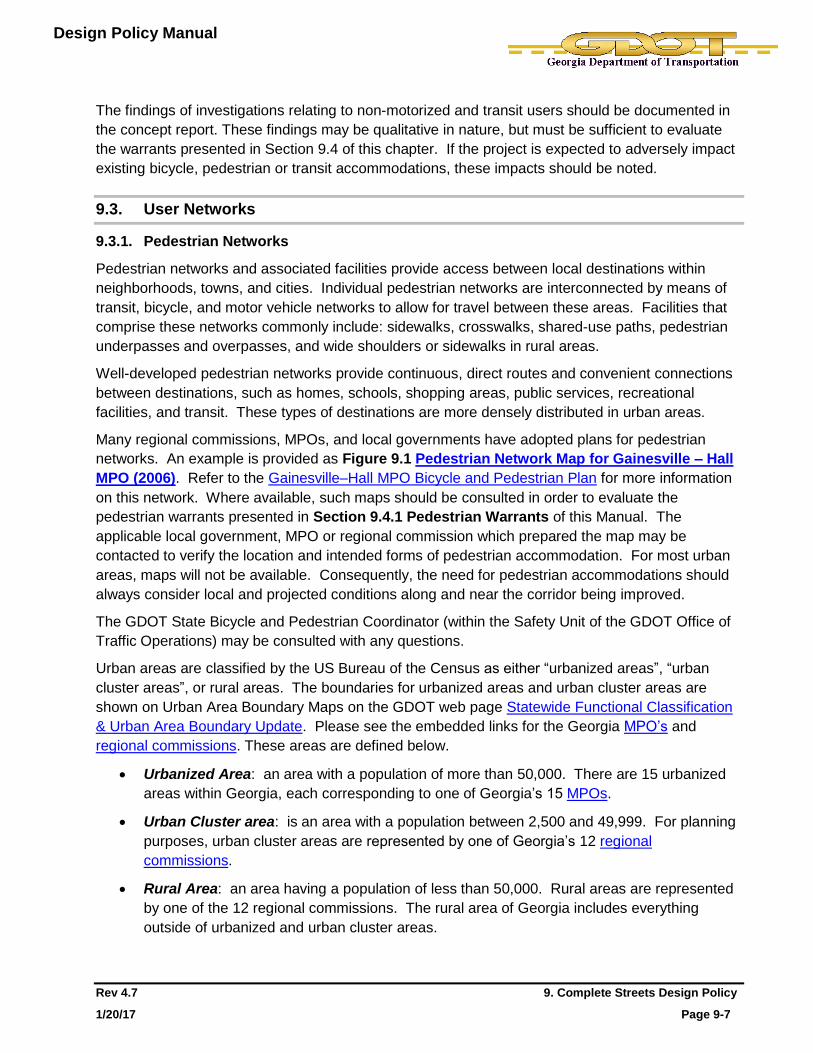
Many regional commissions, MPOs, and local governments have adopted plans for pedestrian
networks. An example is provided as Figure 9.1 Pedestrian Network Map for Gainesville – Hall
MPO (2006). Refer to the Gainesville–Hall MPO Bicycle and Pedestrian Plan for more information
on this network. Where available, such maps should be consulted in order to evaluate the
pedestrian warrants presented in Section 9.4.1 Pedestrian Warrants of this Manual. The
applicable local government, MPO or regional commission which prepared the map may be
contacted to verify the location and intended forms of pedestrian accommodation. For most urban
areas, maps will not be available. Consequently, the need for pedestrian accommodations should
always consider local and projected conditions along and near the corridor being improved.
The GDOT State Bicycle and Pedestrian Coordinator (within the Safety Unit of the GDOT Office of
Traffic Operations) may be consulted with any questions.
Urban areas are classified by the US Bureau of the Census as either “urbanized areas”, “urban
cluster areas”, or rural areas. The boundaries for urbanized areas and urban cluster areas are
shown on Urban Area Boundary Maps on the GDOT web page Statewide Functional Classification
& Urban Area Boundary Update. Please see the embedded links for the Georgia MPO’s and
regional commissions. These areas are defined below.
Urbanized Area: an area with a population of more than 50,000. There are 15 urbanized
areas within Georgia, each corresponding to one of Georgia’s 15 MPOs.
Urban Cluster area: is an area with a population between 2,500 and 49,999. For planning
purposes, urban cluster areas are represented by one of Georgia’s 12 regional
commissions.
Rural Area: an area having a population of less than 50,000. Rural areas are represented
by one of the 12 regional commissions. The rural area of Georgia includes everything
outside of urbanized and urban cluster areas.

Design Policy Manual
Rev 4.7 9. Complete Streets Design Policy
1/20/17 Page 9-8
Figure 9.1. Pedestrian Network Map for Gainesville-Hall MPO (2006).
Design Policy Manual
Rev 4.7 9. Complete Streets Design Policy
1/20/17 Page 9-9
9.3.2. Bicycle Networks
Bicycle networks include nearly every roadway in Georgia, with the exception of those routes –
such as interstate highways and other limited access facilities – on which bicycles are specifically
not allowed. These networks include roads of all functional classes, as well as off-road bikeways.
Individual networks have been defined by the GDOT, local governments, MPOs, and regional
commissions to facilitate bicycle travel within urban and rural areas, and to connect metropolitan
areas to regional destinations. Metropolitan and regional destinations include those of important
scenic, historic, cultural, recreational, commercial, educational, and employment value as well as
transit facilities. These individual bicycle networks are often comprised of many individual bicycle
routes.
A state-wide network is formed by linking local/regional bicycle networks to the State of Georgia
Bicycle network. This state-wide network is illustrated on Figure 9.3 Local, Regional, State and
U.S. Bicycle Routes in Georgia. The State of Georgia Bicycle Network is shown in Figure 9.4
State of Georgia Bicycle Network3.
Bicycle Routes
A bicycle route is any road, street, path, or way which is specifically prioritized by a jurisdictional
authority for bicycle travel. These routes are often identified in planning studies, and so there may
or may not be a physical bicycle facility present. Although specific roadways are designated as
preferred routes for bicyclists, bicyclists are allowed to ride on any road legally open to bicycles -
regardless of the presence or absence of physical bicycle accommodations or designations.
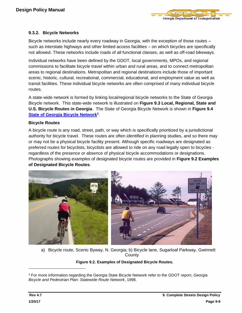
Photographs showing examples of designated bicycle routes are provided in Figure 9.2 Examples
of Designated Bicycle Routes.
a) Bicycle route, Scenic Byway, N. Georgia; b) Bicycle lane, Sugarloaf Parkway, Gwinnett County
Figure 9.2. Examples of Designated Bicycle Routes.
3 For more information regarding the Georgia State Bicycle Network refer to the GDOT report, Georgia Bicycle and Pedestrian Plan: Statewide Route Network, 1998.

Design Policy Manual
Rev 4.7 9. Complete Streets Design Policy
1/20/17 Page 9-10
Figure 9.3 Local, Regional, State and U.S. Bicycle Routes in Georgia Figure 9.4 State of Georgia Bicycle Network (1997).

Design Policy Manual
Rev 4.7 9. Complete Streets Design Policy
1/20/17 Page 9-11
Local and Regional Bicycle Networks
Many regional commissions, MPOs, and local governments have developed bicycle networks
based on regional or local planning studies. An example of a regional commission network (which
includes existing and planned bikeways) is provided in Figure 9.5 Atlanta Regional Commission
(ARC) Bicycle Network Recommendations. Refer to the ARC planning document, Atlanta Region
Bicycle Transportation and Pedestrian Walkways Plan for more information on this network. Many
cities and counties have also adopted bicycle or comprehensive transportation plans; these plans
often include one or more bicycle network maps.
Maps showing bicycle routes are commonly available on web sites for these organizations. These
maps where available must be consulted to evaluate the bicycle warrants presented in Section
9.4.2 Bicycle Warrants of this manual. Prior to the selection and design of accommodations for a
bicycle route, the local government, MPO or regional commission which prepared the map should
be contacted to verify that the map is current and correctly shows the route alignment. The GDOT
State Bicycle and Pedestrian Coordinator can be consulted with any questions, and should be
consulted if maps show conflicting information.
State of Georgia Bicycle Network
The Georgia DOT has developed a network of cross-state bicycle routes to facilitate long-distance
bicycle travel in Georgia (see Figure 9.4., State of Georgia Bicycle Network). These routes
consist primarily (where facilities are present) of on-road facilities, such as paved shoulders and
bicycle lanes, and wayfinding or cautionary signs. Route selection considers the population of the
areas connected rather than populations along the actual route. They support natural connections
between adjoining states; link urban areas, transportation hubs, and major attractions; and provide
access to scenic, cultural, historical, and recreational destinations. Detailed maps for these routes
are available at the following URL: http://www.dot.ga.gov/DriveSmart/Travel/Pages/BikePed.aspx
Routes identified as part of the State of Georgia Bicycle Network shall, at a minimum, comply with
the basic requirements outlined below:
All long-distance bicycle routes will meet the criteria for an approved numbered bicycle route
system established by the American Association of State Highway and Transportation
Officials (AASHTO), Manual on Uniform Traffic Control Devices (MUTCD), and GDOT
guidelines;
Georgia state bicycle routes will be coordinated with neighboring states to ensure
consistency with regional or U.S. Bicycle Route networks and allow for interstate bicycle
travel; and
The addition of accommodations along long-distance bicycle routes should include the
installation of bicycle route number signs and wayfinding or cautionary signs at appropriate
locations.
U.S. Bicycle Route System
The goal of the U.S. Bicycle Route System is to facilitate travel between the states through a
network of numbered interstate bicycle routes (refer to the AASHTO Purpose and Policy, U.S.
Numbered Bicycle Routes). This initiative will help achieve the following two goals identified in the
Georgia Bicycle and Pedestrian Plan:

Design Policy Manual
Rev 4.7 9. Complete Streets Design Policy
1/20/17 Page 9-12
to develop a transportation network of primary bicycle routes throughout the state to provide
connectivity for intrastate and interstate bicycle travel; and
to promote establishment of U.S. numbered bicycle routes in Georgia as part of a national
network of bicycle routes.
USBR 21, which connects Atlanta to Chattanooga, was approved by AASHTO in the fall of 2015.
Three other initial 50-mile wide corridors are being considered for establishment of U.S. Bicycle
Routes in Georgia:
USBR 1, which travels from Camden County (Florida Border) to Chatham County (South
Carolina border) along the coast;
USBR 15, which travels from Lowndes County (Florida border) to the North Carolina border
through the center of the state;
USBR 84, which travels from the South Carolina border to the Alabama border through the
Piedmont Region and Atlanta area;
Detailed routes (turn-by-turn) within these three corridors have yet to be defined. Accordingly,
GDOT is working with the regional commissions, MPOs, local governments, bicycling interest
groups, and managers of bicycle facilities to assess and identify of detailed routes along these
corridors.
Design Policy Manual
Rev 4.7 9. Complete Streets Design Policy
1/20/17 Page 9-13
Figure 9.5. Atlanta Regional Commission (ARC) Bicycle Network Recommendations.
Figure 9.6. Georgia Map Showing Counties with Transit Systems.
Note: Clayton County now has a rural county transit system.

Design Policy Manual
Rev 4.7 9. Complete Streets Design Policy
1/20/17 Page 9-14
9.3.3. Transit Networks
There are a large number of transit agencies in Georgia which form a broad network of fixed route
bus, paratransit, and rail services. This network includes several types of transit service (see below)
as part of 15 urban networks and 111 public transportation programs which cover more than half of
Georgia counties and all 15 MPOs.
Rural transit networks are more numerous than urban transit networks, but urban transit networks
carry a larger number of people. Figure 9.5 Georgia Map Showing Counties with Transit
Systems is available from the GDOT Intermodal Office Transit Program and can be used to identify
counties which have fixed-route transit systems. Maps showing existing and planned transit
networks should be available from transit service providers, local governments, MPOs, and regional
commissions. A GDOT Planner can be contacted to help locate transit maps which apply to a
specific project corridor. For the Atlanta region, refer to the ARC Strategic Regional Thoroughfare
Plan for planned transit routes.
Types of Transit Service
Seven basic types of transit service commonly found in urban and rural transit systems are defined below, the last four of which are high-capacity type transit systems.
Paratransit – regulatory service that must accompany fixed route bus service for qualified
disabled persons; provides demand-response type services. This form of transit is operated
within ¾ of a mile of fixed routes. Trips are utilizing smaller vehicles such as vans, shuttles and
small buses. Accommodations for paratransit are not normally considered when designing
roadway infrastructure projects.
Local Bus – bus service operating at a fixed frequency and serving designated stops along a
fixed route. Local bus service usually operates within the normal travel lanes of the urban
roadway network. MARTA , Cobb County Community Transit, and Chatham Area Transit are
examples of transit agencies which provide local bus service. Although classified as fixed-route
transit, local and express bus routes are more frequently subject to change than other forms of
transit.
Express Bus – similar to local bus but with fewer stops. Express buses normally operate
during peak travel periods and include fewer but longer routes than local bus. Cobb Community
Transit, Gwinnett County Transit, and GRTA are examples of transit agencies which provide
express bus service.
Bus Rapid Transit (BRT) – enhanced bus service with limited stops, and with technology which
helps speed up travel. BRT operates in shared (within designated lanes) or exclusive right-of-
way along urban roadways and freeways.
Rapid Transit Rail – passenger transit service which operates in a separate right-of-way within
an inner-urban area. Rapid transit rail typically carry more passengers than light rail but fewer
than commuter rail. MARTA is an example of a transit agency which provides Rapid Transit
Rail services. MARTA is classified as a Heavy Rail system, which refers to the large number of
passengers the trains can carry, and not the weight.
Commuter Rail – passenger rail transport service that primarily operates between a city center
and the middle to outer suburbs (beyond about 10 miles), commuter towns, or other locations

Design Policy Manual
Rev 4.7 9. Complete Streets Design Policy
1/20/17 Page 9-15
that draw large numbers of commuters. Commuter rail often shares tracks and technology with
a mainline railway system.
Light Rail/Streetcar – Light Rail/Streetcar is also a fixed guideway transit system and operates
in a variety of environments. These environments include: an exclusive right-of-way, a shared
right-of-way (either in a median or parallel to the roadway), or in-street operation with other
vehicles (i.e., streetcars). Vehicles lengths can range from short rail cars similar to a bus or
multiple car trains. Because of their design, light rail systems typically operate at lower speeds
and feature closely spaced stops. The Atlanta Streetcar is an example of a streetcar system.
9.4. Warrants for Accommodation
The Georgia Department of Transportation has established the following standard and guideline
warrants to ensure that appropriate pedestrian and bicycle accommodations are included in
transportation infrastructure projects. These warrants apply to roadways where pedestrians and
bicyclists are permitted to travel. In a similar manner, warrants for transit accommodations are
presented. Warrants must be evaluated as part of project concept development, and documented in
the concept report.
If it is not practical to include the appropriate accommodation where a “Standard” warrant
criterion is met, then agency approval and documentation will be required by formal Design
Variance before the necessary accommodation can be excluded from the project. To obtain
a Design Variance, a comprehensive study and formal request shall be submitted using the
template provided in Appendix D of the GDOT Project Development Process (PDP). Refer
also to Section 2.2 of this Manual.
Local Governments are encouraged to apply Complete Streets principals wherever it is practical to
do so. Since the Local Maintenance and Improvement Grant Program (LMIG) is a state-funded
grant program, GDOT oversight after the application process is normally limited. Therefore, it is not
the intention of the Department to monitor application of Complete Streets policies to LMIG projects.
Complete Streets policies do apply to all TE, TAP and LCI projects, and the application of these
policies is monitored as part of GDOT’s normal oversight of these programs.
9.4.1. Pedestrian Warrants
Standard – Pedestrian accommodations shall be considered in all planning studies, and be
included in all reconstruction, new construction, and capacity-adding projects which include curb
and gutter as part of an urban border area (See Figure 6.3). Pedestrian accommodations shall also
be considered along roadways with rural shoulders, which meet any of the following conditions:
1. along corridors with pedestrian travel generators and destinations (i.e. residential
neighborhoods, commercial areas, schools, public parks, transit stops and stations, etc.), or
areas where such generators and destinations can be expected prior to the design year of
the project;
2. where there is evidence of pedestrian traffic (e.g., a worn path along roadside);
3. where pedestrian crashes equal or exceed a rate of ten for a ½-mile segment of roadway,
over the most recent five years for which crash data is available; and
Design Policy Manual
Rev 4.7 9. Complete Streets Design Policy
1/20/17 Page 9-16
4. where a need is identified by a local government, MPO or regional commission through an
adopted planning study.
Guideline – Pedestrian accommodations should be considered on projects that are located in
areas with any of the following conditions:
1. within close proximity (i.e., a 1 mile radial distance) of a school, college, university, or major
public institution (e.g., hospital, major park, etc.);
2. within an urbanized area; or area projected to be urbanized by an MPO, regional
commission, or local government prior to the design year of the project;
3. where there is an occurrence of pedestrian crashes; and
4. any location where engineering judgment, planning analysis, or the public involvement
process indicates a need.
The need for pedestrian accommodation for access to transit facilities should be evaluated as part
of Section 9.4.3 Transit Warrants.
9.4.2. Bicycle Warrants
Standard – Bicycle accommodations shall be considered in all planning studies and shall be
included in all reconstruction, new construction, and capacity-adding projects that are located in
areas with any of the following conditions:
1. if the project is on a designated (i.e., adopted) U.S., State, regional, or local bicycle route;
2. where there is an existing bikeway along or linking to the end of the project alignment (e.g.,
shared lane, paved shoulder, bike lane, shared-use path, or cycle track);
3. along project alignments with bicycle travel generators and destinations (i.e. residential
neighborhoods, commercial centers, schools, colleges, scenic byways, public parks, transit
stops/stations, etc.);
4. on all new and widened bridges;
5. on retained bridges where a bridge deck is being replaced or rehabilitated and the existing
bridge width allows for a wide enough shoulder for bike accommodations (i.e. ≥ 5 ft) without
eliminating (or precluding) needed pedestrian accommodations – reference Title 23 United
States Code, Chapter 2, Section 217, Part (e); and
6. where there is an occurrence of reported bicycle crashes which equals or exceeds a rate of
five for a 1-mile segment of roadway, over the most recent five years for which crash data is
available.
Guideline – Bicycle accommodations should be considered on projects that are located in areas
with any of the following conditions:
1. within close proximity (i.e., a 3 mile radial distance) of a school, college, university, or major
public institution (e.g., hospital, major park, etc…);
2. where a project will provide connectivity between two or more existing bikeways or connects
to an existing bikeway;
3. where there is an occurrence of bicycle crashes;

Design Policy Manual
Rev 4.7 9. Complete Streets Design Policy
1/20/17 Page 9-17
4. along a corridor where bicycle travel generators and destinations can be expected prior to
the design year of the project;
5. any location where engineering judgment, planning analysis, or the public involvement
process indicates a need.
On resurfacing projects, GDOT will consider requests from local governments to narrow or reduce
the number of travel lanes in order to restripe the roadway to add bicycle lanes. Restriping that
includes narrowing of the travel lanes will be considered where space is available and where the
motor vehicle crash rate for sideswipe crashes (for the most recent five years for which data is
available) does not exceed the statewide average for the same functional classification. A marked
shared lane may be considered if sufficient width is not available for a bicycle lane and motor
vehicle travel speeds are 35 mph or less.
The need for bicycle accommodations for access to transit facilities should be evaluated as part of
Section 9.4.3 Transit Warrants.
9.4.3. Transit Warrants
Standard – Transit accommodations shall be considered in all planning studies and be included in
all reconstruction, new construction, and capacity-adding projects that are located in areas with any
of the following conditions:
1. transit vehicles: on corridors served by fixed-route transit; and
2. pedestrian transit users: within a ¾- mile pedestrian catchment area of an existing fixed-
route transit facility (i.e., stop, station, or park-and-ride lot). A catchment area is defined by a
radial distance from a transit facility per Federal Transit Administration (FTA) guidelines -
this includes crossing and intersecting streets.
Guideline – Transit accommodations should be considered on projects that are located in areas
with any of the following conditions:
1. bicyclist transit users: within a 3-mile bicycle catchment area of an existing fixed-route transit
facility;
2. transit vehicles: along a corridor programmed (and funded) to begin construction of high-
capacity transit before the roadway project design year; and
3. all transit users: between transit stops/stations and local destinations.
Where a warrant is met, the need for accommodations should be validated through coordination
with the transit service provider (and MPO, regional commission and/or local government, where
applicable). This coordination is necessary for existing as well as planned transit facilities. It should
be recognized that although classified as fixed-route transit, local and express bus routes are
periodically changed in order to improve service to riders.
9.4.4. Exclusions
The consideration of bicycle and pedestrian warrants may be excluded from roadways for any of the following conditions:
1. for very low speed (i.e., < 35mph), low volume residential roadways where pedestrians and
bicyclists can comfortably share the roadway with motor vehicles;

Design Policy Manual
Rev 4.7 9. Complete Streets Design Policy
1/20/17 Page 9-18
2. on side road tie-ins where there is no existing sidewalk or bicycle accommodation and
widening of construction limits for sidewalk or bicycle accommodation would result in
disproportionate impacts to adjacent property, as decided by the project development team
on a case-by-case basis; and
3. sidewalks are not required in rural areas where curb and gutter is placed at the back of the
useable shoulder solely for the purpose of reducing construction limits and/or meeting MS4
requirements.
Accommodation, based on meeting a Standard Warrant, may only be omitted after approval of a
Design Variance as defined under Section 9.4, Warrants for Accommodation. Justification may
be in the form of demonstrating that the cost of providing the required accommodations is
“excessively disproportionate” to the need or probable use of that accommodation.
“Excessively disproportionate” may be defined as exceeding 20% of the total project cost. This cost
should consider construction, required right-of-way, environmental impacts, and in some cases
operation and maintenance. Where accommodations provide safety benefits to address bicycle
and/or pedestrian crash history, these benefits must be considered.
9.5. Design of Accommodations
9.5.1. Pedestrian Accommodation Design
A variety of pedestrian groups utilize pedestrian facilities, as briefly described in Section 9.2.1
Pedestrians of this Manual. Their abilities vary significantly; in terms of agility, balance, cognition,
coordination, endurance, flexibility, hearing, problem solving, strength, vision, and walking speed.
Accordingly, pedestrian accommodations must be designed to be readily accessible and usable by
all pedestrian groups.
The Americans with Disabilities Act (ADA) of 1990 and Section 504 of the Rehabilitation Act were
passed to protect these rights. ADA requirements that specifically address public rights-of-way are
contained in the Proposed Accessibility Guidelines for Pedestrian Facilities in the Public Right-of-
Way (PROWAG) which is located on the United States Access Board web site. These guidelines
cover access to public rights-of-way; including sidewalks, intersections, street crossings, and on-
street parking.
These requirements apply to all: (1) newly constructed facilities, (2) altered portions of existing
facilities, and (3) elements added to existing facilities which include pedestrian circulation and use
within the public right-of-way. They also apply to temporary facilities, such as would be in place
during staged construction. These requirements do not apply to existing pedestrian
accommodations which are not within the scope of the project.
The Georgia DOT has summarized in the remainder of this section, criteria for designing accessible
pedestrian accommodations in Georgia. These criteria comply with the PROWAG, but in some
cases are more selective (e.g., a GDOT 5-ft minimum sidewalk width, compared to the PROWAG
minimum of 4-ft). If it is not practical to meet the more selective GDOT criteria, then the designer
shall, at a minimum, comply with the criteria defined in the PROWAG. Refer to the complete
PROWAG for these criteria.

Design Policy Manual
Rev 4.7 9. Complete Streets Design Policy
1/20/17 Page 9-19
Where pedestrian accommodations are provided, they must be accessible by all potential
users. Therefore, GDOT adopts the PROWAG requirements as minimum standards for the
design of pedestrian accommodations. If meeting a PROWAG requirement is either
structurally impractical, technically infeasible, or will result in an unsafe condition, then a
decision to select a value or retain an existing condition that does not meet the criteria
defined in the PROWAG shall require a comprehensive study by an engineer and the prior
approval of a Design Variance from the GDOT Chief Engineer.
Structurally Impractical – this applies to new construction only. “New construction”, for the
purposes of these requirements, is defined as construction of a roadway where an existing roadway
does not currently exist. “Structural impracticability” is limited only to those rare situations when the
unique characteristics of terrain make it physically impossible to construct facilities that are fully
compliant with the PROWAG.
If full compliance with PROWAG is structurally impracticable (based on an approved Design
Variance), compliance is required to the extent that it is not structurally impracticable.
Technically Infeasible – this applies to alterations and elements added to existing facilities. An
alteration is a change to an existing transportation facility that affects or could affect pedestrian
access, circulation, or use. Alterations include reconstruction, rehabilitation, widening, resurfacing,
or projects of similar scale and effect. “Technical infeasibility” is something that has little likelihood
of being accomplished because existing structural conditions would require removing or altering a
load-bearing member that is an essential part of the structural frame; or because other existing
physical and site constraints prohibit modification or addition of elements, spaces, or features to
fully comply with the requirements of the PROWAG.
If full compliance with PROWAG is technically infeasible (based on an approved Design Variance),
compliance is required to the extent that it is not technically infeasible. Examples of existing
physical or site constraints that may make compliance technically infeasible include, the following
(Refer to PROWAG Section R202 Alterations and Elements Added to Existing facilities):
Right-of-way acquisition in order to achieve full compliance is not mandatory (where no
other right-of-way is being acquired), but should be considered. Improvements may be
limited to the maximum extent practicable within the existing right-of-way.
Underground structures that cannot be moved without significantly expanding the project
scope.
Adjacent developed facilities, including buildings that would have to be removed or
relocated to achieve accessibility.
Drainage cannot be maintained if the feature is made accessible.
Notable natural or historic features that would have to be altered in a way that lessens
their aesthetic or historic value.
Underlying terrain that would require a significant expansion of the project scope to
achieve accessibility.
Street grades within the crosswalk exceed the pedestrian access route maximum cross
slopes, provided an engineering analysis has concluded that it cannot be done without
Design Policy Manual
Rev 4.7 9. Complete Streets Design Policy
1/20/17 Page 9-20
significantly expanding the project scope (for example, changing from resurfacing to
reconstructing of the intersection).
Safety Considerations - when accessibility requirements would cause safety issues, compliance is
required to the maximum extent practicable. A design variance is still required.
Reduction in Access – whatever decisions are made relating to structural impracticality or technical
infeasibility, the addition or alteration of pedestrian accommodations shall not have the result of
reducing the existing level of accessibility below the minimum PROWAG requirements.
Location of Sidewalk
Sidewalks are routinely provided along urban shoulders. Refer to Section 6.7 Border Area (urban
shoulder) of this Manual for information on urban shoulders. Sidewalks, shared-use paths, and
walkable shoulders are examples of pedestrian accommodations which can be provided along rural
shoulders. Figure 9.7a and Figure 9.7b illustrates the location of these pedestrian
accommodations on urban and rural shoulders, respectively.
Pedestrian Buffer Area
A pedestrian buffer area (often referred to as a “buffer strip” or “landscaping strip”) separates the
sidewalk and the vehicle traveled way, as the physical area between the back of curb and the
roadside edge of sidewalk. The buffer strip allows room to place utilities, bus stops, landscaping,
street furniture, signs, and mail boxes without obstructing the pedestrian travel way, as well as
providing comfort and safety benefits for walkers.
GDOT recommends a 6-ft wide buffer strip between the back of curb and the sidewalk. If a roadway
has multiple driveways, a 6-ft buffer strip will provide the offset required to connect the sidewalk
along the back of a standard concrete valley gutter driveway, without a shift in the sidewalk
alignment. A buffer strip also provides some protection from overhanging objects from vehicles, and
also creates a psychological barrier, enhancing pedestrian comfort. Grassing or pavers for the
buffer strip are preferred, to provide a color contrast which helps visually impaired pedestrians to
better distinguish between the sidewalk and roadway.
The buffer strip width should be no less than 2-ft. This reduced width may be appropriate where the
separation between travel lanes and the sidewalk is increased by the inclusion of on-street parking
or bicycle lanes.
Where right-of-way constraints will not permit a 2-ft buffer width, sidewalk may be constructed
adjacent to the back of curb. This may occur, for example, in central business districts where
buildings are located immediately adjacent to the back of sidewalk. In this case, a wider sidewalk
may be necessary.
Width of Sidewalk
GDOT’s minimum sidewalk width is 5-ft. When right-of-way is limited at intersections, the designer
should be careful not to violate this requirement by placing a sign post, signal mast arm, signal
cabinet, strain pole, pedestrian signal pedestal, or any other fixed object in a way that would reduce
this width. Such “point narrowing” of the sidewalk width may be acceptable in isolated cases as
long as there is at least 4-ft of clear unobstructed space. At medians and pedestrian refuge islands
the clear width shall be no less than 5-ft.
Design Policy Manual
Rev 4.7 9. Complete Streets Design Policy
1/20/17 Page 9-21
The PROWAG Section R302.4 Passing Spaces, states that “Where the clear width of pedestrian
access routes is less than 1.5 m (5.0 ft), passing spaces must be provided at intervals of 61 m
(200.0 feet) maximum. Passing spaces must be 1.5 m (5.0 ft) minimum by 1.5 m (5.0 ft) minimum.
Passing spaces are permitted to overlap pedestrian access routes.”
Higher pedestrian usage may warrant the use of wider sidewalks. Sidewalks wider than 5-ft may be
appropriate to accommodate higher pedestrian flows refer to Toolkit 5 of the GDOT Pedestrian and
Streetscape Guide or Section 3.2.3 of the AASHTO Guide for the Planning, Design, and Operation
of Pedestrian Facilities.
Sidewalk Grade
Steep grades and cross slopes should be avoided where possible. The longitudinal slope (or
grade) of a sidewalk shall not exceed the general grade established for the adjacent street or
roadway. In cases where sidewalk alignment deviates from the adjacent roadway, the longitudinal
slope of the sidewalk shall not exceed 5%.
Sidewalk Cross-Slope
The maximum allowable sidewalk cross-slope is 2.0%.
Crosswalks
The grade at pedestrian street crossing shall not exceed 5%.
The cross slope for pedestrian street crossings with yield or stop control shall be no greater than
2%. Allowances for cross slope are made for street crossings without yield or stop control where
vehicles can proceed through the intersection without stopping (5% max) and at midblock locations
(may equal the street grade). Refer to Section R302.6 Cross Slope for more information relating
to cross slope at pedestrian street crossings.
Refer to Section 12.2.3 of the GDOT Signing and Marking Design Guidelines and in GDOT
Construction Detail T-11A for guidance relating to crosswalk location and design.
Sidewalk Surface
Sidewalk surfaces shall be firm, stable and slip-resistant, and comply with the following
requirements:
Vertical alignments must be generally planar and smooth. Changes in level are vertical
rises between adjacent surfaces; including bumps, utility castings, expansion joints, etc.
Changes in level shall not exceed ¼-in. without a bevel.
Changes in level between ¼-in. and ½-in. shall be beveled to a slope no steeper than
1V:2H. The bevel shall be applied to the entire vertical surface of the discontinuity.
Sidewalk areas with changes in level greater than ½-in. must be replaced or repaired.
Horizontal openings of more than ½ in. cannot be retained. Elongated openings in grates
shall be placed so that the long dimension is perpendicular to the dominant direction of
travel.
Flangeway gaps at pedestrian at-grade rail crossings shall be no more than 2.5-in. wide
on non-freight rail track and 3-in. wide on freight rail track.

Design Policy Manual
Rev 4.7 9. Complete Streets Design Policy
1/20/17 Page 9-22
These requirements also apply to other elements of pedestrian circulation paths, including:
pedestrian street crossings and at-grade railroad crossings, pedestrian underpasses and
overpasses, and curb ramps and blended transitions.
Curb Ramps and Blended Transitions
Accessible curb ramps or blended transitions must be provided at all pedestrian street crossings. Curb
ramps are ramps that are cut through or built up to the curb, and can be perpendicular or parallel, or
a combination of the two. Blended transitions are raised pedestrian street crossings, depressed
corners, or similar connections between the sidewalk and street level. These are illustrated and
briefly described in the FHWA, Accessible Sidewalks and Street Crossings – An Informational
Guide. A helpful summary of the advantages and disadvantages of each is also provided.
Additional information is provided in the GDOT Pedestrian Streetscape Guide.
Perpendicular curb ramps are aligned perpendicular to the traffic they are crossing and guide
pedestrians directly into the crosswalk. Turning space for wheel chairs is provided at the top of the
ramp. This type of curb ramp is to be used wherever feasible. Parallel curb ramps have a running
slope that is in-line with the direction of sidewalk travel and provide turning space at the bottom of
the ramp. A parallel curb ramp may be used where there is little or no room between the sidewalk
and curb for a perpendicular curb ramp.
A separate curb ramp is required at each pedestrian street crossing for new construction. For
alterations, a single diagonal curb ramp is allowed where existing constraints prevent two curb ramps
from being installed.
Curb ramp design shall comply with requirements in Section R304 Curb Ramps and Blended
Transitions of the PROWAG. Refer to GDOT Construction Standards and Details, Construction
Details A‐2, A‐3, and A‐4 for construction details relating to curb ramps. See Chapter 11.1 of this
Manual for guidance for when ADA curb ramps must be installed or repaired as part of pavement
activities classified as “alterations”.
Detectable Warning Surfaces
Detectable warnings are a standardized surface feature built into or applied to walking surfaces to
warn visually impaired people of potential hazards. Specifically, they indicate a boundary where a
pedestrian accommodation and a roadway meet in a flush manner. They are placed at the bottom
of curb ramps and at other locations such as depressed corners, borders of medians and islands, at
the edge of transit platforms and where railroad tracks cross the sidewalk. Refer to GDOT
Construction Detail A-4.
Refer to PROWAG Sections R208 and R305 Detectable Warning Surfaces for detailed
guidance.
Mid-Block Crossings
Mid-block crossings should be considered where pedestrian mid-block crossing movements are
heavy, such as may occur at transit stops or where there are clear origins/destinations located
across from each other (e.g., between an apartment complex and grocery store, a school and a
park, or a transit stop and a residential neighborhood); and where there is a long distance between
crosswalks. Mid-block crossings should be evaluated on a case-by-case basis and an appropriate
treatment selected based pedestrian needs, and both roadway and traffic conditions.

Design Policy Manual
Rev 4.7 9. Complete Streets Design Policy
1/20/17 Page 9-23
Some common mid-block crossing treatments include: marked crosswalks, Pedestrian Hybrid
Beacons (PHB), Rectangular Rapid Flashing Beacons (RRFB), bulb outs, median refuge islands,
and raised crosswalks. Enhancements may be required such as lighting, signage, and pavement
marking.
Pedestrian refuge islands that are cut-though at street level should be no less that 6-ft in length, in
the direction of pedestrian travel. Refer to Section R305.2.4 Pedestrian Refuge Islands of the
PROWAG.
For more guidance on when to use median islands, refer to the FHWA Safety Effects of Marked
Versus Unmarked Crosswalks at Uncontrolled Locations. Refer to Section 12.4 of the GDOT
Signing and Marking Design Guidelines for design guidance on marked crosswalks at controlled
and uncontrolled intersections. For additional information on mid-block crossings and treatments
refer to the AASHTO Guide for the Planning, Design, and Operation of Pedestrian Facilities, the
GDOT Pedestrian and Streetscape Guide, the AASHTO Guide for Geometric Design of Transit
Facilities on Highways and Streets, and the FHWA Manual on Uniform Traffic Control Devices
(MUTCD).
At-Grade railroad Crossings
Refer to the PROWAG for requirements relating to at-grade railroad crossings.
Roundabouts
The PROWAG Section R306.3.2 Pedestrian Activated Signals states that, “At roundabouts with
multi-lane pedestrian street crossings, a pedestrian activated signal complying with R209 shall be
provided for each multi-lane segment of each pedestrian street crossing, including the splitter
island.” It is GDOT current practice to install necessary conduit across all roundabout multilane
pedestrian crossings, from shoulder to splitter island, in the location required for installation of a
future pedestrian signal. The pedestrian signal could then be installed later if the above
requirement is unchanged when the PROWAG is finally adopted by the US Department of Justice.
Pedestrian Signals
Refer to the MUTCD for guidance relating to accessible pedestrian signals and pedestrian push buttons. These should be provided when new pedestrian signals are installed. Also, refer to the GDOT Traffic Signal Design Guidelines manual.
Transit Stops and Shelters
Refer to the PROWAG Section R308 Transit Stops and Transit Shelters and the AASHTO Guide
for Geometric Design of Transit Facilities on Highways and Streets. New or altered bus loading
pads shall meet the following criteria:
Provide a firm, stable, and slip resistant surface.
Provide a minimum clear length of 8 feet (measured from the curb or roadway edge) and
minimum clear width of 5 feet (measured parallel to the roadway).
Connect the pad to streets, sidewalks, or pedestrian circulation paths with at least one
accessible route.
The slope of the pad parallel to the roadway will be the same as the roadway to the extent
practicable.

Design Policy Manual
Rev 4.7 9. Complete Streets Design Policy
1/20/17 Page 9-24
Provide a desirable cross slope of 1.5% up to a maximum cross slope of 2.0%
perpendicular to the roadway.
On-Street Parking
Refer to the PROWAG Section R214 and R309 On-Street Parking Spaces.
Bridges
A typical sidewalk width across a bridge in an urban area is 5’-6” and does not include a buffer strip
between the back of curb and sidewalk. Therefore, the width of the sidewalk should transition from
the roadway cross section to the bridge cross section before the approach slab. This will include
eliminating the buffer strip in advance of the bridge.
Tapering down a sidewalk and buffer strip to match the bridge shoulder is typically accomplished in
a space between 50-ft to 100-ft in advance of the bridge. Where guardrail is used on the bridge
approaches, the sidewalk transition should follow the guardrail offset transition.
Work Zones
Pedestrian access routes must be provided when a pedestrian circulation path is temporarily closed
by construction, alterations, maintenance operations or other conditions. The alternate pedestrian
route must comply with MUTCD standards. Refer to pedestrian accessibility requirements in GDOT
Special Provision, Section 150.02 – K. Pedestrian Considerations. The current GDOT SP 150
– Traffic Control is located on GDOT’s website at the following address:
http://www.dot.ga.gov/PartnerSmart/Business/Source/special_provisions/shelf/sp150.pdf

Design Policy Manual
Rev 4.7 9. Complete Streets Design Policy
1/20/17 Page 9-25
.
Figure 9.7a Illustrations of Pedestrian Accommodations on an Urban Shoulder

Design Policy Manual
Rev 4.7 9. Complete Streets Design Policy
1/20/17 Page 9-26
Figure 9.7b Illustrations of Pedestrian Accommodations on a Rural Shoulder

Design Policy Manual
Rev 4.7 9. Complete Streets Design Policy
1/20/17 Page 9-27
9.5.2. Bicycle Accommodation Design
GDOT adopts the guidance published in the 2012 AASHTO Guide for the Development of Bicycle
Facilities (AASHTO Guide) for the selection and design of bicycle accommodations. Use of the
2015 FHWA Separated Bikeway Planning and Design Guide (FHWA Guide) and the NACTO Urban
Design Guide (NACTO Guide) is encouraged in urban areas. Design should also consider local
and regional bicycle design guidelines, where these guidelines are consistent with one of the three
“Guides” mentioned above. Refer to the MUTCD and the GDOT Signing and Marking Design
Guidelines for signing and marking requirements related to bicycle facilities.
Selection of Bikeway Type
Bikeway type should be selected based on context sensitive4 design principles, which includes
consideration of the needs of typical users, characteristics of the roadway corridor, accessibility of
the facility to area destinations, and other considerations. Coordination with the local government
having jurisdiction and/or the local planning agency will be helpful in understanding this context.
The most appropriate bikeway type should be selected only after careful examination of bicyclist
needs and local conditions along the street or corridor involved.
Bikeways may be classified as either on-road or off-road facilities. Common on-road facilities
include bicycle lanes, buffered bike lanes, and shared lanes. Common off-road facilities include
shared-use paths located either on independent right-of-way or adjacent to the roadway (i.e., a
sidepath). Separated bike lanes may be either on-road or off-road bikeways, and are sometimes
referred to as “cycle tracks” or “protected bike lanes.” Refer to the AASHTO Guide for more
information about on-road and off-road bikeways, and the FHWA Guide for more information about
separated bike lanes.
On-road bikeways allow bicyclists to circulate with traffic, allow easier access to destinations, and
help bicyclists behave more predictably. Off-road bikeways may allow greater separation from high-
speed traffic but need careful consideration at driveways, intersections, and constrained areas.
For urban areas, on-street bicycle lanes, on-street buffered bike lanes, and separated bike lanes
are preferred over shared lanes because they provide a separate or more visible facility, which
increases user safety and comfort. If an existing bicycle facility is present in the form of a shared
lane, consideration should be given to upgrading the facility to one of these three. Where children
are an important user group for a bicycle facility (e.g., in the vicinity of a school, park, family
attraction, etc…), a separated facility should be considered, such as a separated bike lane or
shared-use path.
Bikeable Shoulders (rural areas)
A bikeable shoulder is appropriate for rural areas and consists of a 4-ft 2-in. width of smooth
pavement on a 6.5-ft wide paved shoulder. Bikeable shoulders are separated from vehicular traffic
4 Context sensitive design may be defined as a collaborative, interdisciplinary process which involves all stakeholders to design a transportation facility that fits its applicable setting and preserves scenic, aesthetic, historic and environmental resources while maintaining safety and mobility. This process balances design objectives for safety, efficiency, capacity and maintenance while integrating community objectives relating to compatibility, livability, sense of place, urban design, cost and environmental impacts.

Design Policy Manual
Rev 4.7 9. Complete Streets Design Policy
1/20/17 Page 9-28
by a 16-in rumble strip, offset 12 inches from the edge of traveled way. These rumble strips are
designed with a skip pattern to allow bicyclists to safely enter and exit the shoulder. Refer to
Georgia Construction Detail S-8 for additional information. A bikeable shoulder is illustrated in
Figure 9.8 Illustration of a Bikeable Shoulder.
Shared Lanes
A shared lane requires that motorized vehicles and bicycles share the outside travel lane of the
roadway. A shared roadway may include pavement markings in the form of a marked shared lane
which provides wayfinding guidance to bicyclists and alerts drivers that bicyclists are likely to be
operating in the roadway travel lanes. Shared lanes may be used where space constraints or other
limitations do not allow for the width required for a bicycle lane or as otherwise appropriate per the
AASHTO Guide (specifically refer to Table 2-3).
Where posted speeds do not exceed 35 mph and it is desirable to provide a higher level of
guidance to bicyclists and motorists a marked shared lanes can be considered (refer to the 2009
MUTCD Section 9C.07 and Section 4.4 of the AASHTO Guide). Marked shared lanes scan be used
to fill gaps on a corridor where bicycle lanes are the prevailing facility, but space constraints or other
limitations do not permit a continuous bikeway. Proper striping transitions should be provided
between the two types of bikeways.
On-Street Bicycle Lanes
An on-street bicycle lane consists of a bike lane designated by striping, signing and pavement
markings, and commonly provides for one-way travel, in the same direction as the adjacent travel
lane. GDOT has defined 4-ft as the minimum width for on-street bicycle lanes in areas with 2.5-ft
curb and gutter, as illustrated in Figure 9.8 Illustration of a Bikeable Shoulder and a Bicycle
Lane. The 4-ft bicycle lane is developed between the traveled way and gutter, and so does not
include the gutter width. The minimum bike lane width is 5-ft for areas where the bike lane is
immediately adjacent to a curb, guardrail or other vertical surface. If the space to the right of the
traveled way striping is less than 4-ft wide, the route cannot be signed or marked as a “bicycle
lane”.
A width greater than 4-ft may be appropriate in some cases - refer to Section 4.6.4 and 4.6.5 of the
AASHTO Guide. Where on-street parking is permitted, the minimum bike lane width is 5-ft. Two
feet of additional width should be provided for bicycle lanes located adjacent to on-street parking,
where practical. Bicycle safe grates are required on drop inlets for roadways where bicycles are
permitted.
On-Street Buffered Bike Lanes
On-street buffered bike lanes are similar to on-street bike lanes, except that a pavement marking
buffer is used to increase lateral separation between bicyclist and motor vehicles. On-street
buffered bike lanes should be considered for roadways with posted or operating speeds of 35 mph
or greater. The painted buffer should be at least 2-ft wide. Refer to the NACTO Guide for
additional information.
Separated Bike Lanes
Separated Bike lanes are defined in the FHWA Guide, as follows:
Design Policy Manual
Rev 4.7 9. Complete Streets Design Policy
1/20/17 Page 9-29
A separated bike lane is an exclusive facility for bicyclists that is located within or directly adjacent to the roadway and that is physically separated from motor vehicle traffic with a vertical element. Separated bike lanes are differentiated from standard and buffered bike lanes by the vertical element. They are differentiated from shared use paths (and sidepaths) by their more proximate relationship to the adjacent roadway and the fact that they are bike-only facilities. Separated bike lanes are also sometimes called “cycle tracks” or “protected bike lanes.”
Within the common elements of separated bike lanes – dedicated space for cyclists that is
separated from motor vehicle travel and parking lanes – practitioners have flexibility in choosing
specific design elements. Separated bike lanes can operate as one-way or two-way facilities;
their designs can integrate with turning automobile traffic at intersections or can be more fully
separated; they can be designed at roadway grade, at sidewalk grade or at an intermediate
grade; and they can be separated from the adjacent roadway or sidewalk with a variety of
treatments including but not limited to on-street parking, raised curbs or medians, bollards,
landscaping, or planters.
Refer to the FHWA Guide for design guidance relating to separated bike lanes.
Shared-Use Paths (Bicyclist & Pedestrian)
A shared-use path is a combined bikeway and pedestrian facility located within an independent
right-of-way, or located within the roadway right-of-way, and physically separated from motor
vehicle traffic by an open space or barrier (i.e., a sidepath). Because a shared-use path is not an
exclusive bicycle facility, it should not normally be considered as an “equal” alternative to an on-
road bikeway paths. It may be used to supplement a network of on-road bicycle facilities.
Most shared-use paths are designated for two-way travel and are designed for both transportation
and recreation purposes. Shared-use path design is similar to roadway design, but on a smaller
scale and with typically lower design speeds (refer to Chapter 5 of the AASHTO Guide). Shared-
use paths are also be used by pedestrians, skaters, equestrians, and other non-motorized users
and should be designed accordingly. These facilities must meet all applicable ADA requirements
(refer to Section 5.1.1 of the AASHTO Guide).
Sidepaths are a specific type of shared-use path that run adjacent to the roadway and should only
be used after considering potential conflicts associated with sidepaths (refer to Section 5.2.2 of the
AASHTO Guide). Sidepaths may be considered where one or more of the following conditions exist
(Page 5-10 of the AASHTO Guide):
The adjacent roadway has relatively high-volume and high-speed motor vehicle traffic that might
discourage bicyclists from riding on the roadway, potentially increasing sidewalk riding, and
there are no practical alternatives for either improving the roadway or accommodating bicyclists
on nearby parallel streets.
The sidepath is used for a short distance to provide continuity between sections of path in
independent rights-of-way, or to connect local streets that are used as bicycle routes.
The sidepath can be built where there are few roadway and driveway crossings. (A pair of
sidepaths – one on each side of the roadway - may be considered for roadways with frequent
cross-streets and driveways. Each sidepath would be signed for one-way bicycle traffic.)

Design Policy Manual
Rev 4.7 9. Complete Streets Design Policy
1/20/17 Page 9-30
The sidepath can be terminated (at each end) onto streets that accommodate bicyclists, onto
another path, or in a location that is otherwise bicycle compatible.
Intersections and Connections Between Different Bikeway Types
The design of bikeways should give particular attention to providing connections between on-road
and off-road bikeways and reducing bicyclist/motorized vehicle conflicts at cross-streets, driveways
and other intersections (refer to Sections 4.8 and 5.3 of the AASHTO Guide).

Design Policy Manual
Rev 4.7 9. Complete Streets Design Policy
1/20/17 Page 9-31
Figure 9.8 Illustrations of a Bikeable Shoulder and a Bicycle Lane.

Design Policy Manual
Rev 4.7 9. Complete Streets Design Policy
1/20/17 Page 9-32
9.5.3. Transit Accommodation Design
One of the most important considerations for ensuring safe and convenient access to transit stops
and facilities is to provide accommodations that allow users to cross the road to access these
facilities. This is of particular concern as a disproportionately high number of pedestrian crashes
occur at transit stops. Accordingly, each transit stop should be evaluated to ensure that adequate
crossing opportunities are provided. This may include relocation of the bus stop where safe access
cannot be otherwise provided.
Along with accessibility, other accommodations may need to be considered. Examples include bus
pullouts, lane width, intersection turning radii, lane and signal prioritization, and signage, and space
for transit stop amenities. Transit stop locations should be placed to not affect the sight distance of
nearby crossroads.
Transit user accommodations commonly include pedestrian/bicycle accommodations that provide
safe and convenient access to a transit facility. For the design of accommodations which address
user access to a transit facility refer to Sections 9.5.1 Pedestrian Facility Design and 9.5.2
Bicycle Facility Design of this Manual.
For transit user accommodations at a transit facility (e.g., most commonly a concrete bus loading
pad for a transit stop) and for transit vehicle accommodations refer to the following publications:
Guide for Geometric Design of Transit Facilities on Highways and Streets, AASHTO, 2014;
Guide for High-Occupancy Vehicle (HOV) Facilities, AASHTO, 2004;
Guide for the Design of Park-and-Ride Facilities, AASHTO, 2004; and
Guidelines for the Location and Design of Bus Stops (TCRP Report 19), TCRP, 1996.
Pedestrian Safety Guide for Transit Agencies. FHWA, 2008.
In most cases, high capacity transit vehicle accommodations (e.g., traffic signal preemption, queue-
jumper lanes) would be included as part of a transit-focused project. Preservation of right-of-way
may be considered as part of a roadway project.
The location, selection, and design of accommodations at a transit facility and for transit vehicles
should be coordinated with the affected transit service provider and local government, where
applicable.
9.6. Acknowledgements
The GDOT Complete Streets Design Policy was developed by the GDOT Division of Engineering in
coordination with the Divisions of Operations and Permits, Planning, and Intermodal. The Division
of Engineering acknowledges and appreciates the efforts of Byron Rushing for his part in helping
develop the original GDOT Bicycle and Pedestrian policy and for his assistance with expanding that
policy to its present form, as a Complete Streets policy.
The GDOT Division of Engineering also acknowledges and appreciates the efforts of the below
individuals who provided valuable comments on draft versions of this policy.
Byron Rushing, Amy Goodwin ARC
Rebecca Serna Atlanta Bicycle Coalition

Design Policy Manual
Rev 4.7 9. Complete Streets Design Policy
1/20/17 Page 9-33
Brent Buice Georgia Bikes!
Joshuah Mello, Alexandra Frackelton
City of Atlanta
Amanda Thompson City of Decatur
Robert Dell-Ross, Andrew Antweiler
City of Roswell
Laraine Vance Cobb Community Transit
- Georgia Municipal Association
Brian Borden Georgia Regional Transportation Authority (GRTA)
Vince Edwards Gwinnett County Transit
Donald Williams, John Crocker, Tameka Wimberly
Metropolitan Atlanta Rapid Transit Authority (MARTA)
Barbara McCann, Stefanie Seskin
Smart Growth America - National Complete Streets Coalition
Sally Flocks PEDS
Keith Melton USDOT Federal Transit Administration (FTA)
Andrew Edwards USDOT FHWA Georgia Division
Design Policy Manual
Rev 4.7 9. Complete Streets Design Policy
1/20/17 Page 9-34
Intentionally Left Blank